A6 to Manchester Airport Relief Road. B003 Mill Lane Accommodation Bridge Preliminary Design Report Report No. 1007/704/151
|
|
|
- Claud Fitzgerald
- 6 years ago
- Views:
Transcription

1 A6 to Manchester Airport Relief Road B003 Mill Lane Accommodation Bridge Report No. 1007/704/151 August 2013
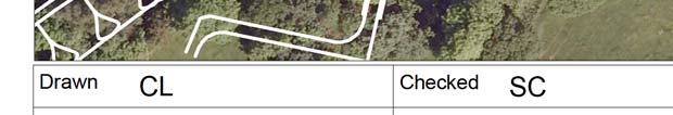
2 PRELIMINARY DESIGN REPORT Structure Name : Structure Number : Mill Lane Accommodation Bridge B003 Report No. 1007/704/151 Report Control Sheet Version Date Status Prepared By Checked By Approved By P1 29/08/2013 Draft J Watton M Ellis N Sheena P2 13/09/2013 Final J Watton M Ellis N Sheena
3 B003- Mill Lane Accommodation Bridge Stockport Metropolitan Borough Council Table of Contents 1. Description of Site Highway Details Proposed Structure Span Arrangements Headroom and Clearances Road Restraint System (Bridge Parapets) Preferred Structural Options Superstructure Options Substructure Options Geotechnical Information Appearance... 7 Appendix A: Location Plans Appendix B: Proposed General Arrangement Drawing 3D Model Appendix C: Ground Investigation Information
 and is proposed to give farmers, pedestrians, cyclists and equestrian access across")
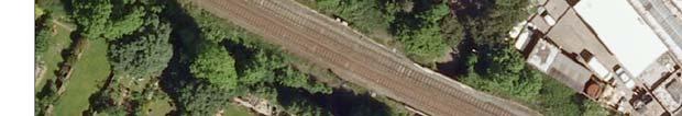
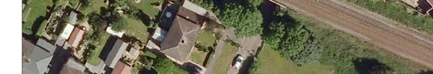
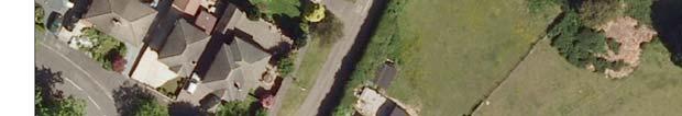
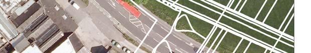
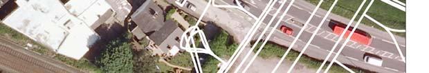
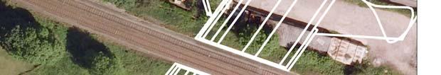
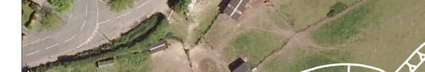
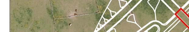
4 B003- Mill Lane Accommodation Bridge Stockport Metropolitan Borough Council 1. Description of Site The Mill Lane Accommodation Bridge is part of the A6 to Manchester Airport Relief Road (A6MARR) and is proposed to give farmers, pedestrians, cyclists and equestrian access across the relief road. The bridge is to be located approximately 100m and 140m south-west of Buxton railway and Buxton Road respectively at route chainage 8670m approximately. There are a large number of residential properties on Mill Lane to the north of the site and several on Old Mill Lane to the west of the proposed bridge crossing. The immediate surrounding area of the proposed bridge is open farm land. An aerial location plan at 1:1250 scale is included in Appendix A. 2. Highway Details Over Structure Mill Lane Accommodation Bridge 3.0m wide single carriageway with two verges and string courses. (2 x 0.5m verges + 3.0m carriageway + 2 x 0.5m string courses) Under Structure Relief road (26m) with a central reserve of 3.9m. Typical dimensions and arrangement are as follows: A6MARR typical cross section 3. Proposed Structure The proposed structure will be a single span fully integral construction bridge. The superstructure will be in the form of pre-cast pre-stressed concrete U-beams and an in-situ reinforced concrete (R.C.) slab deck. The bridge superstructure will be supported on full height R.C. abutments which will be founded on bored piles. In-situ reinforced concrete wing walls, founded on piles, are also proposed. A proposed General Arrangement drawing is included in Appendix B. 4. Span Arrangements The bridge will be a zero skew single span of 27.2m, measured between the centres of each abutment, orientated square to the relief road. 5. Headroom and Clearances Over a highway, the headroom under new bridge is required to be at least 5.3m plus sag compensation in accordance with TD27/05. Therefore, with this clearance the superstructure need not be designed for impact loads.
5 B003- Mill Lane Accommodation Bridge Stockport Metropolitan Borough Council 6. Road Restraint System (Bridge Parapets) The bridge parapets will be type N2 steel parapet with galvanised steel mesh infill in accordance with TD 19/06 and the Road Restraints Risk Assessment Process (RRRAP). Working width class is to be no greater than W4 and will be decided in the final phase of the design. Parapet height is to be 1.8m above finished road level at both verges to accommodate equestrian access and a 600mm high solid infill panel should be provided at the bottom of the parapet to obstruct an animal s view of the road below. 7. Preferred Structural Options 7.1 Superstructure Options It is proposed that the bridge will be a single span, fully integral pre-cast prestressed concrete U-beams supporting an in-situ reinforced concrete slab deck. Refer to drawing 1007/3D/DF7/A6-MA/B003/701 and the 3D Model in Appendix B for further details. For a span range up to 30m, fully integral construction is normally considered a cost effective option. Elimination of movement joints removes a major cause of maintenance problems from penetration of dirt, water and de-icing salts, which corrode substructures and bearings. The advantages for using pre-cast concrete beam construction are as follows: Low capital & whole-life cost Fast and efficient build Factory quality with engineered tolerances Low maintenance The beams can be lifted individually Permanent formwork provides self-supporting system during construction and eliminates falsework Reduces site works which are weather dependent Disadvantages: Precast concrete beams are usually heavier than comparable steel beams. As a result larger cranes might be required to lift the precast concrete beams Heavier superstructure mentioned above might lead to larger foundation sizes Delivery times are dependent on a specialist supplier
6 B003- Mill Lane Accommodation Bridge Stockport Metropolitan Borough Council 7.2 Substructure Options It is proposed that the bridge will be supported on full height in-situ reinforced concrete wall abutments. They are regarded as the most suitable option considering the topography of the site, existing ground level and the feasibility of the work. The R.C. wall abutments will be founded on piles in order to reduce settlements from the embankment and bridge loading. Further discussion regarding the geotechnical assessment is addressed in Section 8 of this report. 8. Geotechnical Information The bridge is located across the line almost exactly above BH1003 (Geotechnical Engineering, 2005). This shows the ground conditions to likely be: A thin band of sandy CLAY 0.50m thick overlying; Medium dense to dense SAND and GRAVEL, becoming sandy slightly clayey GRAVEL to a depth of 3.40m bgl; Beneath this is cohesive GLACIAL TILL to 4.80m bgl which rests on: Weathered MUDSTONE bedrock. The weathered Mudstone is described as very weak with approximately 40% of its volume weathered to a sandy clay matrix to a depth of 5.40m bgl. The Mudstone is underlain by; Moderately strong fine and medium grained SANDSTONE encountered to a depth of 5.85m bgl; Weak to moderately weak SILTSTONE was then recorded to a depth of 7.00m bgl being completely weathered in places between 6.00 and 7.00m bgl; Moderately strong MUDSTONE was then encountered to a depth of 8.70m bgl overlying; Moderately strong SILTSTONE was encountered to a depth of the Siltstone was interbedded with thin beds of sandstone and mudstone throughout; Weak MUDSTONE was found to underlie the Siltstone to a depth of 13.55m bgl. The Mudstone was interbedded with thin bands of Sandstone. Strong SANDSTONE was then encountered to termination depth of 14.70m bgl. Groundwater was not encountered prior to use of water flush so an accurate GWL could not be obtained from the drilling. Subsequent monitoring of the standpipe installation showed that the highest groundwater level recorded was 4.71m bgl. A review of the abandonment plans for the Poynton and Norbury collieries shows that the new location for B003 is not underlain by any historical workings and no movement is therefore expected from historic mine workings. As there is only one borehole in the new proposed location for B003 this is considered insufficient and at least two additional holes, one either side of the proposed road, should be drilled to a depth of at least 10.00m bgl to confirm the ground conditions at the bridge abutments. The bridge abutments are to be located at the base of the cutting slope adjacent to the proposed road. The foundations are expected to rest on the bedrock at the base of the proposed cutting. Due to the large moments to be resisted it will be necessary to employ piled foundations socketed into the underlying bedrock. To resist the
7 B003- Mill Lane Accommodation Bridge Stockport Metropolitan Borough Council overturning moments it is considered that relatively short large diameter bored piles will be the most suitable. The results of rock testing resulting from the additional boreholes will be required to determine bearing capacity and lateral load resistance for the rock 9. Appearance The superstructure on elevation comprises of approximately 1.47m deep pre-cast beams and 0.67m string course spanning across the relief road. The beams and slab deck will have a plain concrete finish. In addition, N2 steel parapets will be mounted on the string courses at either side of the bridge with the exposed faces of the abutments and wing walls to be ribbed concrete. Precamber may be introduced to give the bridge a more aesthetically pleasing elevation view. (Please refer to the 3D view of the bridge included in Appendix B).
8 B003- Mill Lane Accommodation Bridge Stockport Metropolitan Borough Council Appendix A: Location Plans


9

10
11 B003- Mill Lane Accommodation Bridge Stockport Metropolitan Borough Council Appendix B: Proposed General Arrangement Drawing 3D Model

12

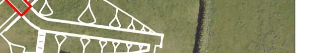
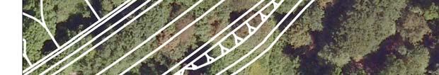
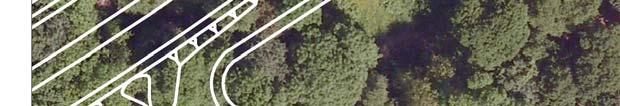
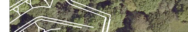
13 B002 Hazel Grove to Buxton Railway Bridge SEMMMS Westbound SEMMMS Eastbound Footpath FP109 Diversion B003 Mill Lane Accommodation Bridge View Looking North
14 B003- Mill Lane Accommodation Bridge Stockport Metropolitan Borough Council Appendix C: Ground Investigation Information
15 Geotechnical Engineering Limited BOREHOLE LOG CLIENT STOCKPORT METROPOLITAN BOROUGH COUNCIL SITE SEMMMS Sheet BH of 2 Start Date April 7, 2005 Easting Scale 1 : 50 End Date April 8, 2005 Northing Ground level mOD Depth m progress date/time water depth sample no & type depth (m) from to casing depth (m) test type & value samp. /core range instru -ment description depth (m) reduced level (m) legend 07/04/ hrs 1D* 2D* 3D* 4D 5X nil S 31 TOPSOIL. (Drillers description) (TS - TOPSOIL) Sandy CLAY. (Drillers description) (GFC - GLACIO-FLUVIAL COHESIVE) SAND and GRAVEL. (Drillers description) (S&G - SAND & GRAVEL) Dense red and orange-brown silty very sandy angular to subrounded fine to coarse predominantly sandstone GRAVEL with occasional fine gravel size coal fragments. (GFG - GLACIO-FLUVIAL GRAVEL) X X nil C m: Becoming medium dense. Very stiff indistinctly structured red-brown locally grey and orange slightly sandy CLAY with occasional subangular fine and medium mudstone lithorelicts. (CT - COHESIVE TILL) X C m: Drilling disturbed. Geotechnical Engineering Ltd, Tel GPJ TRIALJH.GPJ GEOENGV49.GLB 9/5/05 9C 10C 11C casing (m) EQUIPMENT: Geotechnical Pioneer rig C* C* time to rise (min) remarks Very weak red-brown MUDSTONE comprising frequent angular blocky fine and medium lithorelicts in a very stiff slightly sandy clay matrix (40%). (MST - MUDSTONE) m: Bed of stiff red-brown clay with occasional subangular to subrounded fine and medium lithorelicts and green-grey fine gravel size silty reduction spots. Moderately strong red-brown and light grey fine and medium grained SANDSTONE. (SDST - SANDSTONE) m: Bed of moderately weak red-brown thinly laminated siltstone, NI m: 65 curviplanar rough tight sandy clay smeared fracture. Weak to moderately weak grey locally red-brown slightly micaceous SILTSTONE. NI, with very closely spaced randomly orientated planar and irregular rough tight fissures. Fissures are frequently smeared with red-brown clay and occasionally discoloured yellow-brown. (STST - SILTSTONE) m: Locally disintegrated to lithorelicts in a silt matrix. 6.55m: 60mm thick bed of strong fine grained sandstone. Continued Next Page METHOD: Hand dug inspection pit m. Dynamic sampled (128mm) m, (113mm) m. Waterflush rotary core drilled (116mm) m. CASING: 143mm diam to 5.20m. BACKFILL: On completion, a standpipe piezometer (19mm) was installed with tip at 14.70m, granular response zone m, bentonite seal m, concrete and raised cover m. water strike (m) rose to (m) Groundwater not encountered prior to use of water flush {8.00} CONTRACT CHECKED
16 Geotechnical Engineering Limited BOREHOLE LOG CLIENT SITE STOCKPORT METROPOLITAN BOROUGH COUNCIL SEMMMS Sheet BH of 2 Start Date April 7, 2005 Easting Scale 1 : 50 End Date April 8, 2005 Northing Ground level mOD Depth m progress date/time water depth sample no & type depth (m) from to casing depth (m) test type & value samp. /core range instru -ment description depth (m) reduced level (m) legend Geotechnical Engineering Ltd, Tel GPJ TRIALJH.GPJ GEOENGV49.GLB 9/5/05 07/04/ hrs 1.41m 08/04/ hrs 08/04/ hrs 2.26m 12C 13C 14C 15C water strike (m) casing (m) rose to (m) 5.20 C* C** 5.20 C* C* C* time to rise (m) remarks 6.70m: Grading to a very weak indistinctly thinly laminated siltstone. Moderately strong red-grey indistinctly thinly laminated MUDSTONE. Predominantly NI, with extremely closely to closely spaced randomly orientated curviplanar smooth tight fractures frequently with patchy non penetrative orange-brown staining and occasional clay smearing. Locally tending to a siltstone. (MST - MUDSTONE) Moderately strong and strong red-brown and green-grey slightly sandy SILTSTONE with very closely to closely spaced 5-65 planar and curviplanar smooth tight fractures. Fractures are frequently clay smeared with non penetrative orange-brown discolouration. Locally NI. (STST - SILTSTONE) m: With frequent thin occasionally impersistent sandstone interlaminae m: Grading to a thinly interlaminated siltstone and sandstone m: Grading to a strong thinly interlaminated siltstone and sandstone m: Fractures become predominantly closely spaced and inclined at m: Bed of weak red mudstone m: Bed of strong light green-grey fine grained sandstone. NI m: Bed of very stiff slightly sandy very closely fissured clay. Fissures are polished m: Bed of strong light yellow-grey fine grained sandstone m: Drilling disturbed. Weak and moderately weak blue-grey and red-brown MUDSTONE. NI, fractures are extremely closely spaced randomly orientated irregular smooth and frequently polished. Occasional subrounded medium gravel size concretions. (MST - MUDSTONE) 12.30m: 100mm thick bed of clay m: Occasional fractures with non penetrative yellow-brown and patchy black discolouration m: With frequent thin veins and medium gravel size pockets of sandstone m: Bed of strong green-grey siltstone/fine grained sandstone m: 60mm thick bed of stiff friable slightly sandy clay. Strong grey locally red-brown fine to coarse grained SANDSTONE. Predominantly NI, with very closely spaced subhorizontal and subvertical irregular rough open fractures often infilled with firm clay and fine and medium gravel. Some penetrative up to 5mm orange-brown discoloration. (SDST - SANDSTONE) Borehole completed at 14.70m. Groundwater not encountered prior to use of water flush {18.00} CONTRACT CHECKED
Superficial Geology Map - Slice A. Order Details: Order Number: Customer Reference: National Grid Reference: Slice: Site Area (Ha): Search Buffer (m):
: Search Buffer (m):") Superficial Geology Superficial Deposits are the youngest geological deposits formed during the most recent period of geological time, the Quaternary, which extends back about 1.8 million years from the
Superficial Geology Superficial Deposits are the youngest geological deposits formed during the most recent period of geological time, the Quaternary, which extends back about 1.8 million years from the
June 9, R. D. Cook, P.Eng. Soils Engineer Special Services Western Region PUBLIC WORKS CANADA WESTERN REGION REPORT ON
 PUBLIC WORKS CANADA WESTERN REGION REPORT ON GEOTECHNICAL INVESTIGATION PROPOSED MARTIN RIVER BRIDGE MILE 306.7 MACKENZIE HIGHWAY Submitted by : R. D. Cook, P.Eng. Soils Engineer Special Services Western
General. DATE December 10, 2013 PROJECT No TO Mary Jarvis Urbandale/Riverside South Development Corporation
 DATE December 10, 201 PROJECT No. 10-1121-0260- TO Mary Jarvis Urbandale/Riverside South Development Corporation CC Justin Robitaille, Urbandale Jonathan Párraga, J.L. Richards & Associates Limited FROM
Hydro One (Sept 2014) Hydro One (Sept 2014) Hydro One (Sept 2014)
 Hydro One (Sept 2014) Hydro One (Sept 2014)") TABLE 1 WELL CONSTRUCTION DETAILS MOE WWR No Well ID Location Installation Date Status Easting Coordinates Northing Source Elevation Screened Interval Screened Material Borehole Well Stick-up Ground Top
TABLE 1 WELL CONSTRUCTION DETAILS MOE WWR No Well ID Location Installation Date Status Easting Coordinates Northing Source Elevation Screened Interval Screened Material Borehole Well Stick-up Ground Top
LEGEND ODOT CLASS. A-4b. A-6a. A-6b TOTAL VISUAL WEATHERED SANDSTONE VISUAL BORING LOCATION - PLAN VIEW
 PROJECT THE PROJECT CONSISTS IN PART OF ACING TWO STRUCTURES, EASTBOUND AND WESTBOUND STRUCTURES, RESPECTIVELY FOR THE PROPOSED SR OVER BLUE ROAD (CR 9). THE TWO STRUCTURES AS ANNED, ARE SINGLE-SPAN STRUCTURES
LEGEND BUSINESS ZONE NORTH OF AGRESEARCH BOREHOLE CPT SEISMIC CPT AUGER SCALE. Powells Road TEST PIT AGRESEARCH INNOVATION PARK. Hamilton Ring Road
 LEGEND ra R aku Ru BUSINESS ZONE NORTH OF Powells Road oad AGRESEARCH BOREHOLE CPT SEISMIC CPT AUGER SCALE 3 mm TEST PIT AS121 SCPT12 TP18 BH13 TP15 2 AS125 AS126 TP14 BH12 AGRESEARCH CPT13 TP17 INNOVATION
Manor Farm, Otley Road, Adel - preliminary findings
 005/87/ 6 th September 07 Mr G Titchmarsh Titchmarsh & Bagley. Prospect House Sovereign Street Leeds LS BJ Registered in England 07068066 Parkhill Wetherby West Yorkshire LS 5DZ T 097 55 0 www.lithos.co.uk
Eastwood & Partners St. Andrew's House 23 Kingfield Road Sheffield S11 9AS. Co-ords: Level: Dimensions: Depth 1.50m
 epth (m) 0.0 Kingfield Road S AS Coords: imensions: epth.0m epth Level (m) (m AO) Stratum escription 0.0m.0m TOPSOIL: Brown sandy gravelly with rootlets. Gravel is angular to subrounded fine to coarse
14 Geotechnical Hazards
 Volume 2: Assessment of Environmental Effects 296 14 Geotechnical Hazards Overview This Chapter provides an assessment of the underlying geotechnical conditions to identify: any potential liquefaction
Appendix A. Producer Statement Advisory Note
 Appendix A Producer Statement Advisory Note Ref. No. 17095 26 May 2017 PRODUCER STATEMENT CONSTRUCTION REVIEW (PS4) IMPORTANT ADVISORY NOTE The Building Consent Authority (BCA) frequently requires Producer
Chapter 12 Subsurface Exploration
 Page 12 1 Chapter 12 Subsurface Exploration 1. The process of identifying the layers of deposits that underlie a proposed structure and their physical characteristics is generally referred to as (a) subsurface
DRILL HOLE # BH-BGC13-FN-01
 DILL HOLE # BH-BGC3-FN-0 Drill Method: Mud otary/coring Depth To ock (m): N/A Page of 7 eviewed by: AJB 0 GAVEL (GW) Fine to coarse, sandy, well graded, dense, max particle size = 30 mm, angular to subrounded,
Hydrogeological Assessment for Part of Lots 2 and 3, Concession 5, Township of Thurlow, County of Hastings 1.0 INTRODUCTION. 1.
 February 10,2017 25506400 Ontario Ltd. Foxboro, ON Attention: Brad Newbatt Re: Hydrogeological Assessment for Part of Lots 2 and 3, Concession 5, Township of Thurlow, County of Hastings 1.0 INTRODUCTION
ENCE 3610 Soil Mechanics. Site Exploration and Characterisation Field Exploration Methods
 ENCE 3610 Soil Mechanics Site Exploration and Characterisation Field Exploration Methods Geotechnical Involvement in Project Phases Planning Design Alternatives Preparation of Detailed Plans Final Design
SYDNEY MARINE TERMINAL Second Berth Progress
 SYDNEY MARINE TERMINAL Second Berth Progress Second Berth - Project Proponents Second Berth - Project Partners Second Berth - Key Stakeholder Second Berth Project Components New Second Berth: 1 2 Main
Horizontal Directional Drilling: An Approach to Design and Construction. Presenter: John Briand, PE Co-Author: Danielle Neamtu, PE
 Horizontal Directional Drilling: An Approach to Design and Construction Presenter: John Briand, PE Co-Author: Danielle Neamtu, PE Presentation Outline General HDD overview Conceptual-level evaluation Detailed
Subsurface Geology of the Kennebec River
 Maine Geologic Facts and Localities July, 1998 Subsurface Geology of the Kennebec River 43 54 40.75 N, 69 48 29.01 W Text by Daniel B. Locke, Department of Agriculture, Conservation & Forestry 1 Map by
Depth (ft) USCS Soil Description TOPSOIL & FOREST DUFF
 USCS Soil Description TOPSOIL & FOREST DUFF") Test Pit No. TP-6 Location: Latitude 47.543003, Longitude -121.980441 Approximate Ground Surface Elevation: 1,132 feet Depth (ft) USCS Soil Description 0 1.5 1.5 5.0 SM 5.0 8.0 SM Loose to medium dense,
Test Pit No. TP-6 Location: Latitude 47.543003, Longitude -121.980441 Approximate Ground Surface Elevation: 1,132 feet Depth (ft) USCS Soil Description 0 1.5 1.5 5.0 SM 5.0 8.0 SM Loose to medium dense,
Geotechnical Engineering Report
 Geotechnical Engineering Report Turner Turnpike Widening Polecat Creek Bridge (Bridge A) June 1, 2016 Terracon Project No. 04155197 Prepared for: Garver, LLC Prepared by: Terracon Consultants, Inc. TABLE
Geotechnical Engineering Report
 Geotechnical Engineering Report Turner Turnpike Widening Bridge D Bridge Crossing: South 209 th West Avenue Creek County, Oklahoma June 1, 2016 Terracon Project No. 04155197 Prepared for: Garver, LLC Tulsa,
GEOTECHNICAL ENGINEERING II. Subject Code : 06CV64 Internal Assessment Marks : 25 PART A UNIT 1
 GEOTECHNICAL ENGINEERING II Subject Code : 06CV64 Internal Assessment Marks : 25 PART A UNIT 1 1. SUBSURFACE EXPLORATION 1.1 Importance, Exploration Program 1.2 Methods of exploration, Boring, Sounding
Project No: 68R3056 Client: City of Frederick Project: RFQ 14-H Future North Side Water Tank City/State: 7516 Hayward Road, Frederick, MD
 Boring: SB-1 (1 of 1) Moist, brown to orange brown CLAY and SILT, trace sand with fine weathered rock fragments. POSSIBLE FILL. Dry, orange brown sandy SILT trace clay (SM-ML). RESIDUAL SOIL : Not Surveyed
Lake Rotoiti Wastewater Scheme - Stage 1 Investigations. Rotorua Lakes Council
 Lake Rotoiti Wastewater Scheme - Stage 1 Investigations Rotorua Lakes Council i Contents 1 Introduction...1 2 Site Description...1 3 Geological Setting...1 4 Geotechnical Investigation...1 4.1 Borehole
SITE INVESTIGATION 1
 SITE INVESTIGATION 1 Definition The process of determining the layers of natural soil deposits that will underlie a proposed structure and their physical properties is generally referred to as site investigation.
CENTRAL REGION GEOHAZARDS RISK ASSESSMENT SITE INSPECTION FORM
 SITE NUMBER AND NAME C55 H861:02 Slide LEGAL DESCRIPTION NW 14-40-14-W4 CENTRAL REGION GEOHAZARDS RISK ASSESSMENT SITE INSPECTION FORM HIGHWAY & KM NAD 83 COORDINATES N 5811217 E 437291 PREVIOUS INSPECTION
1 PROJECT BACKGROUND. August 14, Alberta Transportation Central Region #401, Street Red Deer, Alberta T4N 6K8
 August 14, 2013 Alberta Transportation Central Region #401, 4902 51 Street Red Deer, Alberta T4N 6K8 Mr. Dennis Grace, P.Eng. Construction Engineer Dear Mr. Grace: Central Region Geohazard Assessment 2013
LEGEND ODOT CLASS A-3. A-3a. A-4a. A-6a. A-6b TOTAL VISUAL VISUAL VISUAL BORING LOCATION - PLAN VIEW
 PROJECT THE PROJECT CONSISTS IN PART OF CONSTRUCTING A SINGLE-SPAN BRIDGE ON RELOCATED SHUMWAY HOOW ROAD OVER THE CSXT RAILROAD. THE STRUCTURE AS ANNED, IS A SINGLE-SPAN STRUCTURE WITH MSE WAS AT THE ABUTMENTS.
Department of National Defence B-Jetty Reconstruction
 Department of National Defence B-Jetty Reconstruction CFB Esquimalt, BC Presented by: Stantec & Golder Associates February 2, 2016 Agenda 1 B-Jetty Project Background 2 Distinguishing Project Features
patersongroup Consulting Engineers April 20, 2010 File: PG1887-LET.01R Novatech Engineering Consultants Suite 200, 240 Michael Cowpland Drive
 patersongroup April 20, 2010 File: PG1887-LET.01R Novatech Engineering Consultants Suite 200, 240 Michael Cowpland Drive Ottawa, Ontario K2M 1P6 Attention: Mr. Adam Thompson Consulting Engineers 28 Concourse
APPENDIX A. Borehole Logs Explanation of Terms and Symbols
 APPENDIX A Borehole Logs Explanation of Terms and Symbols Page 153 of 168 EXPLANATION OF TERMS AND SYMBOLS The terms and symbols used on the borehole logs to summarize the results of field investigation
Geotechnical Data Report
 Geotechnical Data Report Downtown Greenville Future Conveyance Study December 1, 2015 Terracon Project No. 86155032 Prepared for: Prepared by: Terracon Consultants, Inc. December 1, 2015 561 Mauldin Road
16 January 2018 Job Number: RICHARD NEWMAN C\- CLARK FORTUNE MCDONALD AND ASSOCIATES PO BOX 553 QUEENSTOWN
 16 January 2018 Job Number: 50595 RICHARD NEWMAN C\- CLARK FORTUNE MCDONALD AND ASSOCIATES PO BOX 553 QUEENSTOWN CHANSEN@CFMA.CO.NZ STORMWATER DISPOSAL ASSESSMENT Dear Richard, RDAgritech were requested
patersongroup Mineral Aggregate Assessment 3119 Carp Road Ottawa, Ontario Prepared For Mr. Greg LeBlanc March 7, 2014 Report: PH2223-REP.
 Geotechnical Engineering Environmental Engineering group Hydrogeology Geological Engineering Archaeological Studies Materials Testing 3119 Carp Road Prepared For Mr. Greg LeBlanc March 7, 2014 Paterson
Underpinning of York Minster
 Underpinning of York Minster La Reprise en Sous-oeuvre des Fondations de la Cath6drale d'york J.A. LORD Project Director, Ove Arup & Partners, London, United Kingdom S Y N O P S I S F o l l o w i n g a
Geosynthetics Applications and Performance Reviews Select Case Histories
 Geosynthetics Applications and Performance Reviews Select Case Histories Debora J. Miller, Ph.D., P.E.; Dean B. Durkee,, Ph.D., P.E.; Michael A. Morrison, P.E., David B. Wilson, P.E., and Kevin Smith,
Proposed Cemetery Thornhill Road. Tier One Hydrogeological Risk Assessment. Peter Mitchell Associates
 Proposed Cemetery Thornhill Road Tier One Hydrogeological Risk Assessment Peter Mitchell Associates January 2015 Executive Summary This report uses a desk-based risk assessment technique published by the
MAFF Ministry of IfiriLE Agriculture Fisheries and Food
 MAFF Ministry of IfiriLE Agriculture Fisheries and Food STATEMENT OF PHYSICAL CHARACTERISTICS AND AGRICULTURAL LAND CLASSIFICATION UPSLAND, KIRKLINGTON NORTH YORKSHIRE EXTRACTION OF SAND AND GRAVEL MARCH
Construction Exits Vibration grids
 Construction Exits Vibration grids SEDIMENT CONTROL TECHNIQUE Type 1 System Sheet Flow Sandy Soils Type 2 System Concentrated Flow Clayey Soils [1] Type 3 System Supplementary Trap Dispersive Soils [1]
Log of Monitoring Well D58B
 Project: Motiva - Monitoring Well and Soil Boring Data Project Location: Delaware City Refinery Project Number: 20240412.W1000 Log of Monitoring Well D58B Sheet 1 of 7 Date(s) Drilled Drilling Method Drill
APPENDIX A GEOTECHNICAL REPORT
 The City of Winnipeg Bid Opportunity No. 529-2017 Template Version: C420170317 - RW APPENDIX A GEOTECHNICAL REPORT Quality Engineering Valued Relationships KGS Group 2017 Industrial Street Rehabilitation
3.0 SITE COMPARISON GEOLOGY, HYDROGEOLOGY & GEOTECHNICAL 3.1 Comparison of Sites
 APPENDIX TSD#-B COMPARATIVE EVALUATION OF ALTERNATIVE SITES GEOLOGY, HYDROGEOLOGY & GEOTECHNICAL COMPONENT Environmental Component Summary of Site Considerations Interpreted direction of vertical groundwater
Geotechnical Engineering Report
 Geotechnical Engineering Report Turner Turnpike Widening Bridge B Bridge Crossing: South 257 th West Avenue Creek County, Oklahoma June 1, 2016 Terracon Project No. 04155197 Prepared for: Garver, LLC Tulsa,
R.M.HARW & ASSOCIATES LTD. GEOTECHNICAL INVESTIGATION PROPOSED BRIDGE SITE. HELAVA CREEKl MILE MACKENZIE HIGHWAY E-2510 OCTOBER 16, 1973
 El R.M.HARW & ASSOCIATES LTD. GEOTECHNICAL INVESTIGATION PROPOSED BRIDGE SITE HELAVA CREEKl MILE 616.4 MACKENZIE HIGHWAY E-2510 OCTOBER 16, 1973 R,M,HARDV & ASSOCIATES LTD. CONSULTING ENGINEERING & TESTING
ATTACHMENT A PRELIMINARY GEOTECHNICAL SUMMARY
 ATTACHMENT A PRELIMINARY GEOTECHNICAL SUMMARY Kevin M. Martin, P.E. KMM Geotechnical Consultants, LLC 7 Marshall Road Hampstead, NH 0384 603-489-6 (p)/ 603-489-8 (f)/78-78-4084(m) kevinmartinpe@aol.com
Prediction of subsoil subsidence caused by opencast mining
 Land Subsidence (Proceedings of the Fifth International Symposium on Land Subsidence, The Hague, October 1995). IAHS Publ. no. 234, 1995. 167 Prediction of subsoil subsidence caused by opencast mining
Civil Engineering, Surveying and Environmental Consulting WASP0059.ltr.JLS.Mich Ave Bridge Geotech.docx
 2365 Haggerty Road South * Canton, Michigan 48188 P: 734-397-3100 * F: 734-397-3131 * www.manniksmithgroup.com August 29, 2012 Mr. Richard Kent Washtenaw County Parks and Recreation Commission 2330 Platt
 SOIL CLASSIFICATION CHART COARSE-GRAINED SOILS MORE THAN 50% RETAINED ON NO.200 SIEVE FINE-GRAINED SOILS 50% OR MORE PASSES THE NO.200 SIEVE PRIMARY DIVISIONS GRAVELS MORE THAN 50% OF COARSE FRACTION RETAINED
SOIL INVESTIGATION REPORT. PROPOSED HOUSING DEVELOPMENT PROJECT Coral Spring, Trelawny, Jamaica.
 SOIL INVESTIGATION REPORT PROPOSED HOUSING DEVELOPMENT PROJECT Coral Spring, Trelawny, Jamaica. Prepared for: FCS Consultants 7a Barbados Avenue Kingston 5, Jamaica Prepared by: NHL Engineering Limited
Milford Centre Ltd. Private Plan Change GEOTECHNICAL ASSESSMENT
 Milford Centre Ltd. Private Plan Change GEOTECHNICAL ASSESSMENT Final 15 April 2008 Milford Centre Ltd. Private Plan Change GEOTECHNICAL ASSESSMENT Final 15 April 2008 Sinclair Knight Merz 25 Teed Street
ECoast Homes Pty Ltd: Proposed 76-lot subdivision, Penquite Road, Newstead GEOTECHNICAL ASSESSMENT 7 April 2009
 99 Attachment 11 (8 pages including this page) Interpretation of site geology and soils, laboratory test results, and generalised AS2870 classifications 100 Geological setting The proposed subdivision
Safe bearing capacity evaluation of the bridge site along Syafrubesi-Rasuwagadhi road, Central Nepal
 Bulletin of the Department of Geology Bulletin of the Department of Geology, Tribhuvan University, Kathmandu, Nepal, Vol. 12, 2009, pp. 95 100 Safe bearing capacity evaluation of the bridge site along
 TP-1 N61E 0 DARK BROWN SANDY SILT (ML) stiff, wet with roots (Disturbed Surficial Soil) DEPTH (FEET) 5 REDDISH BROWN SANDSTONE intensely fractured, weak to friable, deeply weathered, tight (Franciscan
Saving on the Geotechnical Investigation A False Economy
 Saving on the Geotechnical Investigation A False Economy G. S. Young 1, BE, MEngSc, FIEAust and W. Ellis 2. 1 Douglas Partners Pty Ltd, 96 Hermitage Road, West Ryde, NSW 2114 PH (02) 9809 0666; email:
CONQUEST ENGINEERING LTD.
 CONQUEST ENGINEERING LTD. Geotechnical and Materials Engineers Concrete Technology, Blasting Consultants Construction Quality Assurance / Quality Control 8 Bluewater Road, Bedford, NS BB J6 Phone (9)85-7
10. GEOTECHNICAL EXPLORATION PROGRAM
 Geotechnical site investigations should be conducted in multiple phases to obtain data for use during the planning and design of the tunnel system. Geotechnical investigations typically are performed in
VOLUME III GEOLOGY, HYDROGEOLOGY & GEOTECHNICAL REPORT CAPITAL REGION RESOURCE RECOVERY CENTRE
 VOLUME III GEOLOGY, HYDROGEOLOGY & GEOTECHNICAL REPT CAPITAL REGION RESOURCE RECOVERY CENTRE APPENDIX A Borehole Records December Report No. //vol III LIST OF ABBREVIATIONS The abbreviations coonly employed
HOW. HOW vehicle mounted units portable units also available. HOW, WHEN & WHY to Geophysically Log in S.I.?
 HOW, WHEN & WHY to Geophysically Log in S.I.? by Kim Beesley HOW HOW vehicle mounted units portable units also available Access to borehole Depth of borehole sump / rat -hole? 1 HOW? - subject to borehole
THE INSTITUTE OF COST ACCOUNTANTS OF INDIA (ICAI)
") THE INSTITUTE OF COST ACCOUNTANTS OF INDIA (ICAI) GEOTECHNICAL INVESTIGATION REPORT FOR PROPOSED PROJECT INSTITUTIONAL BUILDING FOR ICAI AT CBD BELAPUR, NAVI MUMBAI OCTOBER 2012 1281-2012-073 BY THANE
THE INSTITUTE OF COST ACCOUNTANTS OF INDIA (ICAI) GEOTECHNICAL INVESTIGATION REPORT FOR PROPOSED PROJECT INSTITUTIONAL BUILDING FOR ICAI AT CBD BELAPUR, NAVI MUMBAI OCTOBER 2012 1281-2012-073 BY THANE
SI Planning & Laboratory Testing for Hill-Site Development
 SI Planning & Laboratory Testing for Hill-Site Development 21 April 2009 IEM Penang Ir. Tan Yean Chin G&P Geotechnics Sdn Bhd Cameron Highlands, 1961 Genting Highland Tower 1993 Bukit Antarabangsa, 1999
 R-1 Conveyor Relocation Project Legend 0 500 1000 1500 ft. This map is a user generated static output from an Internet mapping site and is for general reference only. Data layers that appear on this map
SUMMARY REPORT ON GROUND INVESTIGATIONS AT WALSHESTOWN PIT CO. KILDARE. Submitted to:
 Golder Associates Ireland Town Centre House, Dublin Road, Naas, Co. Kildare, Ireland Tel: [353] (0)45 874411 Fax: [353] (0)45 874549 E-mail: info@golder.ie http://www.golder.com SUMMARY REPORT ON GROUND
The process of determining the layers of natural soil deposits that will underlie a proposed structure and their physical properties is generally
 The process of determining the layers of natural soil deposits that will underlie a proposed structure and their physical properties is generally referred to as sub surface investigation 2 1 For proper
Site Investigations and Geotechnical Risk For Underground Construction Greg Raines, PE
 August 14, 2017 Site Investigations and Geotechnical Risk For Underground Construction Greg Raines, PE Gregory.Raines@Stantec.com Develop Preliminary Geologic / Geotech Conceptual Model for the Project
ABP Southampton. Environmental Statement for Port of Southampton: Berth 201/202 Works. Appendix B. Dredge Material Characterisation
 ABP Southampton Environmental Statement for Port of Southampton: Berth 201/202 Works Appendix B Dredge Material Characterisation Appendix B Dredge Material Characterisation Environmental Statement for
Boreholes. Implementation. Boring. Boreholes may be excavated by one of these methods: 1. Auger Boring 2. Wash Boring 3.
 Implementation Boreholes 1. Auger Boring 2. Wash Boring 3. Rotary Drilling Boring Boreholes may be excavated by one of these methods: 4. Percussion Drilling The right choice of method depends on: Ground
REPORT. Housing Re-Zone. Middle Road and Iona Road - Geotechnical Investigation Report
 REPORT Housing Re-Zone Middle Road and Iona Road - Geotechnical Investigation Report Prepared for Hastings istrict Council Prepared by Tonkin & Taylor Ltd ate April 06 Job Number 464.000 istribution: Hastings
Omaroro Lower Playing Field - Geotechnical Interpretive Report
 Report Omaroro Lower Playing Field - Geotechnical Interpretive Report Prepared for Wellington Water Limited Prepared by Beca Limited 1 December 2017 Omaroro Lower Playing Field - Geotechnical Interpretive
Measurement of effective stress shear strength of rock
 Measurement of effective stress shear strength of rock R. A. Failmezger, P.E., F. ASCE In-Situ Soil Testing, L.C., Lancaster, Virginia USA D. J. White, Ph. D., P.E. Iowa State University, Ames, Iowa USA
Construction Exits Rock pads
 Construction Exits Rock pads SEDIMENT CONTROL TECHNIQUE Type 1 System Sheet Flow Sandy Soils Type 2 System Concentrated Flow [1] Clayey Soils Type 3 System Supplementary Trap Dispersive Soils [1] Minor
East Land Quality Forum Drilling Techniques; Old and New
 East Land Quality Forum Drilling Techniques; Old and New 1 Introduction Different Drilling Methods Rota-sonic drilling What is it and how does it work? Different types of Rota-Sonic/Sonic Drilling Rigs
Piles & Chalk. Lessons Learnt the Hard Way
 Piles & Chalk Lessons Learnt the Hard Way What is Chalk? White Pure Soft & friable What is Chalk? But Can be brown, red, green or grey Can contain clays and other minerals Varies in strength from soft
3.0 SUMMARY OF FINDINGS
 AECOM 500 W Jefferson St. Suite 1600 Louisville, KY 40202 www.aecom.com 502-569-2301 tel 502-569-2304 fax October 17, 2018 Big Rivers Electric Corporation Sebree Generating Station 9000 Highway 2096 Robards,
APPENDIX C. Borehole Data
 APPENDIX C Borehole Data MAJOR DIVISIONS SOIL CLASSIFICATION CHART SYMBOLS GRAPH LETTER TYPICAL DESCRIPTIONS ADDITIONAL MATERIAL
Geology 229 Engineering Geology. Lecture 7. Rocks and Concrete as Engineering Material (West, Ch. 6)
") Geology 229 Engineering Geology Lecture 7 Rocks and Concrete as Engineering Material (West, Ch. 6) Outline of this Lecture 1. Rock mass properties Weakness planes control rock mass strength; Rock textures;
Geology 229 Engineering Geology Lecture 7 Rocks and Concrete as Engineering Material (West, Ch. 6) Outline of this Lecture 1. Rock mass properties Weakness planes control rock mass strength; Rock textures;
Geotechnical Investigation Juneau Seawalk - Taku Fisheries to Miner s Wharf Juneau, Alaska DM&A Job No
 Duane Miller & Associates 5821 Arctic Boulevard, Suite A Anchorage, AK 99518-1654 (907) 644-3200 Fax 644-0507 Arctic & Geotechnical Engineering May 4, 2006 Tetra Tech/KCM, Inc. 1971 First Avenue Seattle,
UNDP HARARE HOSPITAL PROPOSED NATPHARM WAREHOUSE
 UNDP HARARE HOSPITAL PROPOSED NATPHARM WAREHOUSE January 17 2016 TO CARRY OUT IN-SITU SOIL SURVEY, LABORATORY TESTS AND GEOTECHNICAL REPORTING. GEOTECHNICAL INVESTIGATIONS REPORT 1 2 Re: GEOTECHNICAL INVESTIGATIONS
APPROACH FILL DESIGN OF NORTH SASKATCHEWAN RIVER BRIDGE. A.F. Ruban, EBA Engineering Consultants Ltd., Edmonton, Alberta, Canada
 APPROACH FILL DESIGN OF NORTH SASKATCHEWAN RIVER BRIDGE A.F. Ruban, EBA Engineering Consultants Ltd., Edmonton, Alberta, Canada Paper prepared for presentation at the Slope and Embankment Engineering for
APPENDIX E SOILS TEST REPORTS
 Otsego County, NY Site Work Specifications APPENDIX E SOILS TEST REPORTS Blue Wing Services, Inc. July 1, 2010 Blue Wing Services May 20, 2010 Page 2 the site, was not made available to Empire at this
B-1 BORE LOCATION PLAN. EXHIBIT Drawn By: 115G BROOKS VETERINARY CLINIC CITY BASE LANDING AND GOLIAD ROAD SAN ANTONIO, TEXAS.
 N B-1 SYMBOLS: Exploratory Boring Location Project Mngr: BORE LOCATION PLAN Project No. GK EXHIBIT Drawn By: 115G1063.02 GK Scale: Checked By: 1045 Central Parkway North, Suite 103 San Antonio, Texas 78232
Chapter 7 Permeability and Seepage
 Permeability and Seepage - N. Sivakugan (2005) 1 7.1 INTRODUCTION Chapter 7 Permeability and Seepage Permeability, as the name implies (ability to permeate), is a measure of how easily a fluid can flow
IMAGING OF DEEP SINKHOLES USING THE MULTI-ELECTRODE RESISTIVITY IMPLANT TECHNIQUE (MERIT) CASE STUDIES IN FLORIDA
 CASE STUDIES IN FLORIDA") IMAGING OF DEEP SINKHOLES USING THE MULTI-ELECTRODE RESISTIVITY IMPLANT TECHNIQUE (MERIT) CASE STUDIES IN FLORIDA David Harro The G3 Group, 2509 Success Drive, Suite 1, Odessa, FL 33556, david.harro@geo3group.com
IMAGING OF DEEP SINKHOLES USING THE MULTI-ELECTRODE RESISTIVITY IMPLANT TECHNIQUE (MERIT) CASE STUDIES IN FLORIDA David Harro The G3 Group, 2509 Success Drive, Suite 1, Odessa, FL 33556, david.harro@geo3group.com
REPORT. Earthquake Commission. Christchurch Earthquake Recovery Geotechnical Factual Report Bryndwr Appendix C: Borehole Logs
 REPORT Earthquake Commission Christchurch Earthquake Recovery Geotechnical Factual Report Bryndwr Appendix C: Borehole Logs REPORT Earthquake Commission Christchurch Earthquake Recovery Geotechnical Factual
SOIL REPORT FOR BINGARA GORGE DEVELOPMENT SITE Introduction
 SOIL REPORT FOR BINGARA GORGE DEVELOPMENT SITE Introduction On 16 March, 1 April 2016 and 21 September 2016 I undertook soil surveys at Bingara Gorge Development Site, Wilton, and prepared this soil report
DATA REPORT GEOTECHNICAL INVESTIGATION GALVESTON CRUISE TERMINAL 2 GALVESTON, TEXAS
 DATA REPORT GEOTECHNICAL INVESTIGATION GALVESTON CRUISE TERMINAL 2 GALVESTON, TEXAS SUBMITTED TO PORT OF GALVESTON 123 ROSENBERG AVENUE, 8TH FLOOR GALVESTON, TEXAS 77553 BY HVJ ASSOCIATES, INC. HOUSTON,
Module 1 : Site Exploration and Geotechnical Investigation
 Objectives In this section you will learn the following Displacement borings Wash boring Auger boring Rotary drilling Percussion drilling Continuous sampling Boring methods of exploration The boring methods
APPENDIX H SOIL SURVEY
 Environmental Impact Statement Beryl Solar Farm APPENDIX H SOIL SURVEY Beryl Solar Farm 16 347 Final V1 H i Geotechnical Engineers & Engineering Geologists NATA Accredited Laboratories for Asphalt, Aggregate,
How & Where does infiltration work? Summary of Geologic History Constraints/benefits for different geologic units
 June 26, 2007: Low Impact Development 1 Associated Earth Sciences, Inc. Associated Earth Sciences, Inc. Presented by: Matthew A. Miller, PE April 24, 2012 How & Where does infiltration work? Summary of
GEOTECHNICAL INVESTIGATION REPORT PROPOSED MIXED USE DEVELOPMENT 54 PARKWAY DRIVE ROSEDALE, AUCKLAND
 K170412-1 9 August 2017 GEOTECHNICAL INVESTIGATION REPORT PROPOSED MIXED USE DEVELOPMENT 54 PARKWAY DRIVE ROSEDALE, AUCKLAND Prepared For: Lucy Li c/- DCS Ltd Unit 67 Victoria Park Market PO Box 91247,
DRILLED DISPLACMENT PILE PERFORMANCE IN COASTAL PLAIN AND RESIDUAL SOILS
 DRILLED DISPLACMENT PILE PERFORMANCE IN COASTAL PLAIN AND RESIDUAL SOILS Presented by: W. Morgan NeSmith, P.E. Berkel & Company Contractors Inc. 770.941.5100 mnesmith@berkelapg.com SC Engineering Conference
REPORT NO 12/115/D NOVEMBER 2012 GEOTECHNICAL INVESTIGATION FOR THE PROPOSED SOLAR PHOTOVOLTAIC FACILITY, GROOTVLEI POWER STATION
 Consulting Geotechnical Engineers & Engineering Geologists P.O.Box 3557 Cramerview 2060. Tel: (011) 465-1699. Fax: (011) 465-4586. Cell 082 556 7302 & 076 966 8445 REPORT NO 12/115/D NOVEMBER 2012 GEOTECHNICAL
 UNIT DESCRIPTIONS: Artificial Fill, Undocumented (Afu): Locally derived sandy silt and silty sand, locally with clay and varying amounts of gravel and man-made debris. Abundant concrete rubble, in places
M E M O R A N D U M. Mr. Jonathan K. Thrasher, P.E., Mr. Ian Kinnear, P.E. (FL) PSI
 PSI") M E M O R A N D U M TO: FROM: Mr. Mark Schilling Gulf Interstate Engineering Mr. Jonathan K. Thrasher, P.E., Mr. Ian Kinnear, P.E. (FL) PSI DATE: November 11, 2014 RE: Summary of Findings Geotechnical
M E M O R A N D U M TO: FROM: Mr. Mark Schilling Gulf Interstate Engineering Mr. Jonathan K. Thrasher, P.E., Mr. Ian Kinnear, P.E. (FL) PSI DATE: November 11, 2014 RE: Summary of Findings Geotechnical
CONQUEST ENGINEERING LTD.
 CONQUEST ENGINEERING LTD. Geotechnical and Materials Engineers Concrete Technology, Blasting Consultants Construction Quality Assurance / Quality Control 8 Bluewater Road, Bedford, NS BB J6 Phone (9)85-7
Converse Consultants Geotechnical Engineering, Environmental & Groundwater Science, Inspection & Testing Services
 Converse Consultants Geotechnical Engineering, Environmental & Groundwater Science, Inspection & Testing Services July 27, 2017 Ms. Rebecca Mitchell Mt. San Antonio College Facilities Planning & Management
Slope Stability Evaluation Ground Anchor Construction Area White Point Landslide San Pedro District Los Angeles, California.
 Slope Stability Evaluation Ground Anchor Construction Area White Point Landslide San Pedro District Los Angeles, California Submitted To: Mr. Gene Edwards City of Los Angeles Department of Public Works
SHEET PILE WALLS. Mehdi Mokhberi Islamic Azad University
 SHEET PILE WALLS Mehdi Mokhberi Islamic Azad University Lateral Support In geotechnical engineering, it is often necessary to prevent lateral soil movements. Tie rod Anchor Sheet pile Cantilever retaining
BOREHOLE LOCATION PLAN
 BH2/Probe A BH1 Light cable percussion drilling rig Windowless Sampling Borehole and Dynamic Penetration Probing CLIENT: SITE: Date: Abingdon Hydro Ltd Abingdon Hydro Project, Nr Abingdon Wier August 2014
Undrained shear strength
 1.0 SUMMARY This Geotechnical Report relates to a Site Investigation undertaken by Messrs Soil Mechanics Limited on behalf of London Underground Limited involving Package 4 of the proposed Jubilee Line
August 10, 2007 File:
 August 10, 2007 File: 15-85-72 Alberta Infrastructure and Transportation Room 301, Provincial Building 9621-96 Avenue Peace River, AB T8S 1T4 Attention: Mr. Ed Szmata PEACE REGION (PEACE HIGH LEVEL AREA)
Environmental Scoping Report for the proposed establishment of a New Coal-Fired Power Station in the Lephalale Area, Limpopo Province
 8. GEOLOGY, SOILS AND AGRICULTURAL POTENTIAL 8.1. Geology 8.1.1. Candidate Site Geology Due to the layered natured of the geology and various structures the candidate sites are underlain by differing geological