Chapter 3: Block Diagrams and Signal Flow Graphs
|
|
|
- Wendy Lang
- 5 years ago
- Views:
Transcription
1 Chapter 3: Block Diagrams and Signal Flow Graphs Farid Golnaraghi, Simon Fraser University Benjamin C. Kuo, University of Illinois ISBN:
2 Introduction In this chapter, we discuss graphical techniques for modeling control systems and their underlying mathematics. We also utilize the block diagram reduction techniques and the Mason s gain formula to find the transfer function of the overall control system. Later on in Chapters 4 and 5, we use the material presented in this chapter and Chapter 2 to fully model and study the performance of various control systems.
3 Objectives of this Chapter 1. To study block diagrams, their components, and their underlying mathematics. 2. To obtain transfer function of systems through block diagram manipulation and reduction. 3. To introduce the signal flow graphs. 4. To establish a parallel between block diagrams and signalflow graphs. 5. To use Mason s gain formula for finding transfer function of systems. 6. To introduce state diagrams. 7. To demonstrate the MATLAB tools using case studies.
4 3-1 BLOCK DIAGRAMS Block diagrams provide a better understanding of the composition and interconnection of the components of a system. It can be used, together with transfer functions, to describe the cause-and-effect relationships throughout the system. Figure 3-1 A simplified block diagram representation of a heating system.
 Output sensor Actuator Controller Plant (the component whose variables are to be controlled) Input or reference signals Output signals")
5 3-1-1 Typical Elements of Block Diagrams in Control Systems The common elements in block diagrams of most control systems include: Comparators Blocks representing individual component transfer functions, including: Reference sensor (or input sensor) Output sensor Actuator Controller Plant (the component whose variables are to be controlled) Input or reference signals Output signals Disturbance signal Feedback loops Figure 3-3 Block diagram representation of a general control system.
6 Figure 3-4 Block-diagram elements of typical sensing devices of control systems. (a) Subtraction. (b) Addition. (c) Addition and subtraction.

7 Figure 3-5 Time and Laplace domain block diagrams.
8 EXAMPLE Figure 3-6 Block diagrams G1(s) and G2(s) connected in series.
9 EXAMPLE Figure 3-7 Block diagrams G1(s) and G2(s) connected in parallel.

10 Basic block diagram of a feedback control system Figure 3-8 Basic block diagram of a feedback control system.
 2 n () n () n () X s s sx s X s U s x x 2 2 2 ( ) 2 n ( ) n ( ) n ( )")

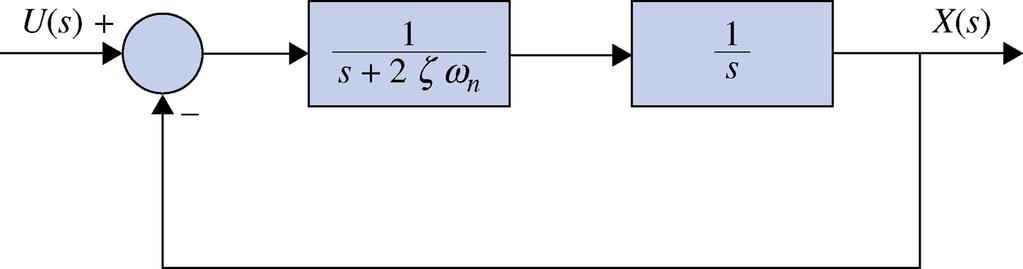
11 3-1-2 Relation between Mathematical Equations and Block Diagrams xt xt xt ut 2 2 () 2 n () n () n () X s s sx s X s U s x x ( ) 2 n ( ) n ( ) n ( ) (assuming zero initial conditions, (0) (0) 0) U() s 2 sx() s X() s X() s s n n n Figure 3-9 Graphical representation of Eq. (3-16) using a comparator.
12 fig_03_12
13 fig_03_13
14 fig_03_14
15 fig_03_15
16 3-1-3 Block Diagram Reduction: Branch point relocation fig_03_16
17 3-1-3 Block Diagram Reduction: Comparator relocation fig_03_17
18 EXAMPLE Find the input output transfer function of the system fig_03_18a
19 fig_03_18b
20 3-1-4 Block Diagram of Multi-Input Systems Special Case: Systems with a Disturbance fig_03_19
21 fig_03_20 fig_03_21

22 fig_03_22 fig_03_23
23
24 3-2 SIGNAL-FLOW GRAPHS (SFGs)
25

26 3-2-7 Gain Formula for SFG
27 fig_03_32
28 fig_03_25
29 Figure 3-33 Signal-flow graph for Example
30 3-2-9 Application of the Gain Formula to Block Diagrams EXAMPLE Figure 3-34 (a) Block diagram of a control system. (b) Equivalent signal-flow graph.
31 Simplified Gain Formula
Automatic Control Systems, 9th Edition
 Chapter 7: Root Locus Analysis Appendix E: Properties and Construction of the Root Loci Automatic Control Systems, 9th Edition Farid Golnaraghi, Simon Fraser University Benjamin C. Kuo, University of Illinois
Control Systems, Lecture 05
 Control Systems, Lecture 05 İbrahim Beklan Küçükdemiral Yıldız Teknik Üniversitesi 2015 1 / 33 Laplace Transform Solution of State Equations In previous sections, systems were modeled in state space, where
SECTION 2: BLOCK DIAGRAMS & SIGNAL FLOW GRAPHS
 SECTION 2: BLOCK DIAGRAMS & SIGNAL FLOW GRAPHS MAE 4421 Control of Aerospace & Mechanical Systems 2 Block Diagram Manipulation Block Diagrams 3 In the introductory section we saw examples of block diagrams
SFG and Mason s Rule : A revision
 SFG and Mason s Rule : A revision Andersen Ang 2016-Nov-29 SFG and Mason s Rule Vu Pham Review SFG: Signal-Flow Graph SFG is a directed graph SFG is used to model signal flow in a system SFG can be used
20.6. Transfer Functions. Introduction. Prerequisites. Learning Outcomes
 Transfer Functions 2.6 Introduction In this Section we introduce the concept of a transfer function and then use this to obtain a Laplace transform model of a linear engineering system. (A linear engineering
Cosc 3451 Signals and Systems. What is a system? Systems Terminology and Properties of Systems
 Cosc 3451 Signals and Systems Systems Terminology and Properties of Systems What is a system? an entity that manipulates one or more signals to yield new signals (often to accomplish a function) can be
Electric Circuit Theory
 Electric Circuit Theory Nam Ki Min nkmin@korea.ac.kr 010-9419-2320 Chapter 18 Two-Port Circuits Nam Ki Min nkmin@korea.ac.kr 010-9419-2320 Contents and Objectives 3 Chapter Contents 18.1 The Terminal Equations
ME 132, Fall 2017, UC Berkeley, A. Packard 317. G 1 (s) = 3 s + 6, G 2(s) = s + 2
 = 3 s + 6, G 2(s) = s + 2") ME 132, Fall 2017, UC Berkeley, A. Packard 317 Be sure to check that all of your matrix manipulations have the correct dimensions, and that the concatenations have compatible dimensions (horizontal concatenations
ME 132, Fall 2017, UC Berkeley, A. Packard 317 Be sure to check that all of your matrix manipulations have the correct dimensions, and that the concatenations have compatible dimensions (horizontal concatenations
Raktim Bhattacharya. . AERO 632: Design of Advance Flight Control System. Preliminaries
 . AERO 632: of Advance Flight Control System. Preliminaries Raktim Bhattacharya Laboratory For Uncertainty Quantification Aerospace Engineering, Texas A&M University. Preliminaries Signals & Systems Laplace
Video 5.1 Vijay Kumar and Ani Hsieh
 Video 5.1 Vijay Kumar and Ani Hsieh Robo3x-1.1 1 The Purpose of Control Input/Stimulus/ Disturbance System or Plant Output/ Response Understand the Black Box Evaluate the Performance Change the Behavior
Dynamics and control of mechanical systems
 Dynamics and control of mechanical systems Date Day 1 (03/05) - 05/05 Day 2 (07/05) Day 3 (09/05) Day 4 (11/05) Day 5 (14/05) Day 6 (16/05) Content Review of the basics of mechanics. Kinematics of rigid
MATHEMATICAL MODELING OF CONTROL SYSTEMS
 1 MATHEMATICAL MODELING OF CONTROL SYSTEMS Sep-14 Dr. Mohammed Morsy Outline Introduction Transfer function and impulse response function Laplace Transform Review Automatic control systems Signal Flow
State Space Control D R. T A R E K A. T U T U N J I
 State Space Control D R. T A R E K A. T U T U N J I A D V A N C E D C O N T R O L S Y S T E M S M E C H A T R O N I C S E N G I N E E R I N G D E P A R T M E N T P H I L A D E L P H I A U N I V E R S I
Professor Fearing EE C128 / ME C134 Problem Set 7 Solution Fall 2010 Jansen Sheng and Wenjie Chen, UC Berkeley
 Professor Fearing EE C8 / ME C34 Problem Set 7 Solution Fall Jansen Sheng and Wenjie Chen, UC Berkeley. 35 pts Lag compensation. For open loop plant Gs ss+5s+8 a Find compensator gain Ds k such that the
Analysis and Design of Control Systems in the Time Domain
 Chapter 6 Analysis and Design of Control Systems in the Time Domain 6. Concepts of feedback control Given a system, we can classify it as an open loop or a closed loop depends on the usage of the feedback.
MODELING OF CONTROL SYSTEMS
 1 MODELING OF CONTROL SYSTEMS Feb-15 Dr. Mohammed Morsy Outline Introduction Differential equations and Linearization of nonlinear mathematical models Transfer function and impulse response function Laplace
Closed Loop Transfer Functions
 Closed Loop Transfer Functions The following script illustrates and demonstrates key control concepts discussed in class on Feb 21 and Feb 23rd. Use these notes to understand how to specify transfer functions
General procedure for formulation of robot dynamics STEP 1 STEP 3. Module 9 : Robot Dynamics & controls
 Module 9 : Robot Dynamics & controls Lecture 32 : General procedure for dynamics equation forming and introduction to control Objectives In this course you will learn the following Lagrangian Formulation
MECHATRONICS CONTROL SYSTEM UNIT II
 MECHATRONICS UNIT II CONTROL SYSTEM Prepared By Prof. Shinde Vishal Vasant Dept. of Mechanical Engg. NDMVP S Karmaveer Baburao Thakare College of Engg. Nashik Contact No- 8928461713 E mail:- nilvasant22@gmail.com
agree w/input bond => + sign disagree w/input bond => - sign
 1 ME 344 REVIEW FOR FINAL EXAM LOCATION: CPE 2.204 M. D. BRYANT DATE: Wednesday, May 7, 2008 9-noon Finals week office hours: May 6, 4-7 pm Permitted at final exam: 1 sheet of formulas & calculator I.
4 Arithmetic of Feedback Loops
 ME 132, Spring 2005, UC Berkeley, A. Packard 18 4 Arithmetic of Feedback Loops Many important guiding principles of feedback control systems can be derived from the arithmetic relations, along with their
Signal Structure for a Class of Nonlinear Dynamic Systems
 Brigham Young University BYU ScholarsArchive All Theses and Dissertations 2018-05-01 Signal Structure for a Class of Nonlinear Dynamic Systems Meilan Jin Brigham Young University Follow this and additional
Alireza Mousavi Brunel University
 Alireza Mousavi Brunel University 1 » Control Process» Control Systems Design & Analysis 2 Open-Loop Control: Is normally a simple switch on and switch off process, for example a light in a room is switched
Control System. Contents
 Contents Chapter Topic Page Chapter- Chapter- Chapter-3 Chapter-4 Introduction Transfer Function, Block Diagrams and Signal Flow Graphs Mathematical Modeling Control System 35 Time Response Analysis of
EC Control Systems- Question bank
 MODULE I Topic Question mark Automatic control & modeling, Transfer function Write the merits and demerits of open loop and closed loop Month &Year May 12 Regula tion Compare open loop system with closed
J א א J א א א F א א א א
 J CHAPTER # 4 SIGNAL FLOW GRAPH (SFG) 1. Introduction For complex control systems, the block diagram reduction technique is cumbersome. An alternative method for determining the relationship between system
Topic # Feedback Control Systems
 Topic #1 16.31 Feedback Control Systems Motivation Basic Linear System Response Fall 2007 16.31 1 1 16.31: Introduction r(t) e(t) d(t) y(t) G c (s) G(s) u(t) Goal: Design a controller G c (s) so that the
Appendix A Complex Variable Theory
 Appendix A Complex Variable Theory TO ACCOMPANY AUTOMATIC CONTROL SYSTEMS EIGHTH EDITION BY BENJAMIN C. KUO FARID GOLNARAGHI JOHN WILEY & SONS, INC. Copyright 2003 John Wiley & Sons, Inc. All rights reserved.
CONTROL SYSTEMS ENGINEERING Sixth Edition International Student Version
 CONTROL SYSTEMS ENGINEERING Sixth Edition International Student Version Norman S. Nise California State Polytechnic University, Pomona John Wiley fir Sons, Inc. Contents PREFACE, vii 1. INTRODUCTION, 1
Nonlinear Control Systems
 Nonlinear Control Systems António Pedro Aguiar pedro@isr.ist.utl.pt 5. Input-Output Stability DEEC PhD Course http://users.isr.ist.utl.pt/%7epedro/ncs2012/ 2012 1 Input-Output Stability y = Hu H denotes
Control Systems I. Lecture 6: Poles and Zeros. Readings: Emilio Frazzoli. Institute for Dynamic Systems and Control D-MAVT ETH Zürich
 Control Systems I Lecture 6: Poles and Zeros Readings: Emilio Frazzoli Institute for Dynamic Systems and Control D-MAVT ETH Zürich October 27, 2017 E. Frazzoli (ETH) Lecture 6: Control Systems I 27/10/2017
INTRODUCTION TO DIGITAL CONTROL
 ECE4540/5540: Digital Control Systems INTRODUCTION TO DIGITAL CONTROL.: Introduction In ECE450/ECE550 Feedback Control Systems, welearnedhow to make an analog controller D(s) to control a linear-time-invariant
Fall 線性系統 Linear Systems. Chapter 08 State Feedback & State Estimators (SISO) Feng-Li Lian. NTU-EE Sep07 Jan08
 Feng-Li Lian. NTU-EE Sep07 Jan08") Fall 2007 線性系統 Linear Systems Chapter 08 State Feedback & State Estimators (SISO) Feng-Li Lian NTU-EE Sep07 Jan08 Materials used in these lecture notes are adopted from Linear System Theory & Design, 3rd.
Fall 2007 線性系統 Linear Systems Chapter 08 State Feedback & State Estimators (SISO) Feng-Li Lian NTU-EE Sep07 Jan08 Materials used in these lecture notes are adopted from Linear System Theory & Design, 3rd.
Dr Ian R. Manchester Dr Ian R. Manchester AMME 3500 : Review
 Week Date Content Notes 1 6 Mar Introduction 2 13 Mar Frequency Domain Modelling 3 20 Mar Transient Performance and the s-plane 4 27 Mar Block Diagrams Assign 1 Due 5 3 Apr Feedback System Characteristics
School of Engineering Faculty of Built Environment, Engineering, Technology & Design
 Module Name and Code : ENG60803 Real Time Instrumentation Semester and Year : Semester 5/6, Year 3 Lecture Number/ Week : Lecture 3, Week 3 Learning Outcome (s) : LO5 Module Co-ordinator/Tutor : Dr. Phang
Outline. Classical Control. Lecture 1
 Outline Outline Outline 1 Introduction 2 Prerequisites Block diagram for system modeling Modeling Mechanical Electrical Outline Introduction Background Basic Systems Models/Transfers functions 1 Introduction
10 Transfer Matrix Models
 MIT EECS 6.241 (FALL 26) LECTURE NOTES BY A. MEGRETSKI 1 Transfer Matrix Models So far, transfer matrices were introduced for finite order state space LTI models, in which case they serve as an important
Contents. PART I METHODS AND CONCEPTS 2. Transfer Function Approach Frequency Domain Representations... 42
 Contents Preface.............................................. xiii 1. Introduction......................................... 1 1.1 Continuous and Discrete Control Systems................. 4 1.2 Open-Loop
Linear System Theory. Wonhee Kim Lecture 1. March 7, 2018
 Linear System Theory Wonhee Kim Lecture 1 March 7, 2018 1 / 22 Overview Course Information Prerequisites Course Outline What is Control Engineering? Examples of Control Systems Structure of Control Systems
Linear State Feedback Controller Design
 Assignment For EE5101 - Linear Systems Sem I AY2010/2011 Linear State Feedback Controller Design Phang Swee King A0033585A Email: king@nus.edu.sg NGS/ECE Dept. Faculty of Engineering National University
ECE317 : Feedback and Control
 ECE317 : Feedback and Control Lecture : Steady-state error Dr. Richard Tymerski Dept. of Electrical and Computer Engineering Portland State University 1 Course roadmap Modeling Analysis Design Laplace
CONTROL * ~ SYSTEMS ENGINEERING
 CONTROL * ~ SYSTEMS ENGINEERING H Fourth Edition NormanS. Nise California State Polytechnic University, Pomona JOHN WILEY& SONS, INC. Contents 1. Introduction 1 1.1 Introduction, 2 1.2 A History of Control
Lecture 5: Linear Systems. Transfer functions. Frequency Domain Analysis. Basic Control Design.
 ISS0031 Modeling and Identification Lecture 5: Linear Systems. Transfer functions. Frequency Domain Analysis. Basic Control Design. Aleksei Tepljakov, Ph.D. September 30, 2015 Linear Dynamic Systems Definition
Coupled Drive Apparatus Modelling and Simulation
 University of Ljubljana Faculty of Electrical Engineering Victor Centellas Gil Coupled Drive Apparatus Modelling and Simulation Diploma thesis Menthor: prof. dr. Maja Atanasijević-Kunc Ljubljana, 2015
D(s) G(s) A control system design definition
 G(s) A control system design definition") R E Compensation D(s) U Plant G(s) Y Figure 7. A control system design definition x x x 2 x 2 U 2 s s 7 2 Y Figure 7.2 A block diagram representing Eq. (7.) in control form z U 2 s z Y 4 z 2 s z 2 3 Figure
R E Compensation D(s) U Plant G(s) Y Figure 7. A control system design definition x x x 2 x 2 U 2 s s 7 2 Y Figure 7.2 A block diagram representing Eq. (7.) in control form z U 2 s z Y 4 z 2 s z 2 3 Figure
Course roadmap. ME451: Control Systems. What is Root Locus? (Review) Characteristic equation & root locus. Lecture 18 Root locus: Sketch of proofs
 Characteristic equation & root locus. Lecture 18 Root locus: Sketch of proofs") ME451: Control Systems Modeling Course roadmap Analysis Design Lecture 18 Root locus: Sketch of proofs Dr. Jongeun Choi Department of Mechanical Engineering Michigan State University Laplace transform
ME451: Control Systems Modeling Course roadmap Analysis Design Lecture 18 Root locus: Sketch of proofs Dr. Jongeun Choi Department of Mechanical Engineering Michigan State University Laplace transform
Control of Electromechanical Systems
 Control of Electromechanical Systems November 3, 27 Exercise Consider the feedback control scheme of the motor speed ω in Fig., where the torque actuation includes a time constant τ A =. s and a disturbance
An Introduction to Control Systems
 An Introduction to Control Systems Signals and Systems: 3C1 Control Systems Handout 1 Dr. David Corrigan Electronic and Electrical Engineering corrigad@tcd.ie November 21, 2012 Recall the concept of a
Today s goals So far Today 2.004
 Today s goals So far Feedback as a means for specifying the dynamic response of a system Root Locus: from the open-loop poles/zeros to the closed-loop poles Moving the closed-loop poles around Today Proportional
Class 27: Block Diagrams
 Class 7: Block Diagrams Dynamic Behavior and Stability of Closed-Loop Control Systems We no ant to consider the dynamic behavior of processes that are operated using feedback control. The combination of
EE451/551: Digital Control. Chapter 3: Modeling of Digital Control Systems
 EE451/551: Digital Control Chapter 3: Modeling of Digital Control Systems Common Digital Control Configurations AsnotedinCh1 commondigitalcontrolconfigurations As noted in Ch 1, common digital control
CDS 101/110a: Lecture 10-1 Robust Performance
 CDS 11/11a: Lecture 1-1 Robust Performance Richard M. Murray 1 December 28 Goals: Describe how to represent uncertainty in process dynamics Describe how to analyze a system in the presence of uncertainty
Extensions and applications of LQ
 Extensions and applications of LQ 1 Discrete time systems 2 Assigning closed loop pole location 3 Frequency shaping LQ Regulator for Discrete Time Systems Consider the discrete time system: x(k + 1) =
EC CONTROL SYSTEM UNIT I- CONTROL SYSTEM MODELING
 EC 2255 - CONTROL SYSTEM UNIT I- CONTROL SYSTEM MODELING 1. What is meant by a system? It is an arrangement of physical components related in such a manner as to form an entire unit. 2. List the two types
A two-port network is an electrical network with two separate ports
 5.1 Introduction A two-port network is an electrical network with two separate ports for input and output. Fig(a) Single Port Network Fig(b) Two Port Network There are several reasons why we should study
Richiami di Controlli Automatici
 Richiami di Controlli Automatici Gianmaria De Tommasi 1 1 Università degli Studi di Napoli Federico II detommas@unina.it Ottobre 2012 Corsi AnsaldoBreda G. De Tommasi (UNINA) Richiami di Controlli Automatici
Control Systems. EC / EE / IN. For
 Control Systems For EC / EE / IN By www.thegateacademy.com Syllabus Syllabus for Control Systems Basic Control System Components; Block Diagrammatic Description, Reduction of Block Diagrams. Open Loop
Vulnerability Analysis of Feedback Systems. Nathan Woodbury Advisor: Dr. Sean Warnick
 Vulnerability Analysis of Feedback Systems Nathan Woodbury Advisor: Dr. Sean Warnick Outline : Vulnerability Mathematical Preliminaries Three System Representations & Their Structures Open-Loop Results:
EEE582 Homework Problems
 EEE582 Homework Problems HW. Write a state-space realization of the linearized model for the cruise control system around speeds v = 4 (Section.3, http://tsakalis.faculty.asu.edu/notes/models.pdf). Use
Control Lab. Thermal Plant. Chriss Grimholt
 Control Lab Thermal Plant Chriss Grimholt Process System Engineering Department of Chemical Engineering Norwegian University of Science and Technology October 3, 23 C. Grimholt (NTNU) Thermal Plant October
Control Systems I. Lecture 7: Feedback and the Root Locus method. Readings: Jacopo Tani. Institute for Dynamic Systems and Control D-MAVT ETH Zürich
 Control Systems I Lecture 7: Feedback and the Root Locus method Readings: Jacopo Tani Institute for Dynamic Systems and Control D-MAVT ETH Zürich November 2, 2018 J. Tani, E. Frazzoli (ETH) Lecture 7:
Actuator Fault Tolerant PID Controllers
 Actuator Fault Tolerant PID Controllers César Castro Rendón Cristina Verde Alejandro Mora Hernández Instituto de Ingeniería-Universidad Nacional Autónoma de México Coyoacán DF, 04510, México cesarcasren@yahoo.com.mx
Chap. 3 Laplace Transforms and Applications
 Chap 3 Laplace Transforms and Applications LS 1 Basic Concepts Bilateral Laplace Transform: where is a complex variable Region of Convergence (ROC): The region of s for which the integral converges Transform
Suppose that we have a specific single stage dynamic system governed by the following equation:
 Dynamic Optimisation Discrete Dynamic Systems A single stage example Suppose that we have a specific single stage dynamic system governed by the following equation: x 1 = ax 0 + bu 0, x 0 = x i (1) where
SECTION 4: STEADY STATE ERROR
 SECTION 4: STEADY STATE ERROR MAE 4421 Control of Aerospace & Mechanical Systems 2 Introduction Steady State Error Introduction 3 Consider a simple unity feedback system The error is the difference between
Last week: analysis of pinion-rack w velocity feedback
 Last week: analysis of pinion-rack w velocity feedback Calculation of the steady state error Transfer function: V (s) V ref (s) = 0.362K s +2+0.362K Step input: V ref (s) = s Output: V (s) = s 0.362K s
Vibration Suppression of a 2-Mass Drive System with Multiple Feedbacks
 International Journal of Scientific and Research Publications, Volume 5, Issue 11, November 2015 168 Vibration Suppression of a 2-Mass Drive System with Multiple Feedbacks L. Vidyaratan Meetei, Benjamin
Using MATLB for stability analysis in Controls engineering Cyrus Hagigat Ph.D., PE College of Engineering University of Toledo, Toledo, Ohio
 Using MATLB for stability analysis in Controls engineering Cyrus Hagigat Ph.D., PE College of Engineering University of Toledo, Toledo, Ohio Abstract Analyses of control systems require solution of differential
Steady State Errors. Recall the closed-loop transfer function of the system, is
 Steady State Errors Outline What is steady-state error? Steady-state error in unity feedback systems Type Number Steady-state error in non-unity feedback systems Steady-state error due to disturbance inputs
Synthesis via State Space Methods
 Chapter 18 Synthesis via State Space Methods Here, we will give a state space interpretation to many of the results described earlier. In a sense, this will duplicate the earlier work. Our reason for doing
Introduction to Process Control
 Introduction to Process Control For more visit :- www.mpgirnari.in By: M. P. Girnari (SSEC, Bhavnagar) For more visit:- www.mpgirnari.in 1 Contents: Introduction Process control Dynamics Stability The
Introduction to Feedback Control
 Introduction to Feedback Control Control System Design Why Control? Open-Loop vs Closed-Loop (Feedback) Why Use Feedback Control? Closed-Loop Control System Structure Elements of a Feedback Control System
The norms can also be characterized in terms of Riccati inequalities.
 9 Analysis of stability and H norms Consider the causal, linear, time-invariant system ẋ(t = Ax(t + Bu(t y(t = Cx(t Denote the transfer function G(s := C (si A 1 B. Theorem 85 The following statements
ECE317 : Feedback and Control
 ECE317 : Feedback and Control Lecture : Routh-Hurwitz stability criterion Examples Dr. Richard Tymerski Dept. of Electrical and Computer Engineering Portland State University 1 Course roadmap Modeling
06 Feedback Control System Characteristics The role of error signals to characterize feedback control system performance.
 Chapter 06 Feedback 06 Feedback Control System Characteristics The role of error signals to characterize feedback control system performance. Lesson of the Course Fondamenti di Controlli Automatici of
Introduction to Controls
 EE 474 Review Exam 1 Name Answer each of the questions. Show your work. Note were essay-type answers are requested. Answer with complete sentences. Incomplete sentences will count heavily against the grade.
Systems Engineering/Process Control L1
 Systems Engineering/Process Control L1 What is Systems Engineering/Process Control? Graphical system representations Fundamental control principles Reading: Systems Engineering and Process Control: 1.1
EE C128 / ME C134 Fall 2014 HW 9 Solutions. HW 9 Solutions. 10(s + 3) s(s + 2)(s + 5) G(s) =
 s(s + 2)(s + 5) G(s) =") 1. Pole Placement Given the following open-loop plant, HW 9 Solutions G(s) = 1(s + 3) s(s + 2)(s + 5) design the state-variable feedback controller u = Kx + r, where K = [k 1 k 2 k 3 ] is the feedback
1. Pole Placement Given the following open-loop plant, HW 9 Solutions G(s) = 1(s + 3) s(s + 2)(s + 5) design the state-variable feedback controller u = Kx + r, where K = [k 1 k 2 k 3 ] is the feedback
ME 132, Dynamic Systems and Feedback. Class Notes. Spring Instructor: Prof. A Packard
 ME 132, Dynamic Systems and Feedback Class Notes by Andrew Packard, Kameshwar Poolla & Roberto Horowitz Spring 2005 Instructor: Prof. A Packard Department of Mechanical Engineering University of California
Radar Dish. Armature controlled dc motor. Inside. θ r input. Outside. θ D output. θ m. Gearbox. Control Transmitter. Control. θ D.
 Radar Dish ME 304 CONTROL SYSTEMS Mechanical Engineering Department, Middle East Technical University Armature controlled dc motor Outside θ D output Inside θ r input r θ m Gearbox Control Transmitter
12.7 Steady State Error
 Lecture Notes on Control Systems/D. Ghose/01 106 1.7 Steady State Error For first order systems we have noticed an overall improvement in performance in terms of rise time and settling time. But there
Process Control and Instrumentation Prof. A. K. Jana Department of Chemical Engineering Indian Institute of Technology, Kharagpur
 Process Control and Instrumentation Prof. A. K. Jana Department of Chemical Engineering Indian Institute of Technology, Kharagpur Lecture - 17 Feedback Control Schemes (Contd.) In the last class we discussed
CONTROL SYSTEMS LECTURE NOTES B.TECH (II YEAR II SEM) ( ) Prepared by: Mrs.P.ANITHA, Associate Professor Mr.V.KIRAN KUMAR, Assistant Professor
 ( ) Prepared by: Mrs.P.ANITHA, Associate Professor Mr.V.KIRAN KUMAR, Assistant Professor") LECTURE NOTES B.TECH (II YEAR II SEM) (2017-18) Prepared by: Mrs.P.ANITHA, Associate Professor Mr.V.KIRAN KUMAR, Assistant Professor Department of Electronics and Communication Engineering MALLA REDDY
LECTURE NOTES B.TECH (II YEAR II SEM) (2017-18) Prepared by: Mrs.P.ANITHA, Associate Professor Mr.V.KIRAN KUMAR, Assistant Professor Department of Electronics and Communication Engineering MALLA REDDY
Uncertainty and Robustness for SISO Systems
 Uncertainty and Robustness for SISO Systems ELEC 571L Robust Multivariable Control prepared by: Greg Stewart Outline Nature of uncertainty (models and signals). Physical sources of model uncertainty. Mathematical
MATH4406 (Control Theory) Unit 1: Introduction Prepared by Yoni Nazarathy, July 21, 2012
 Unit 1: Introduction Prepared by Yoni Nazarathy, July 21, 2012") MATH4406 (Control Theory) Unit 1: Introduction Prepared by Yoni Nazarathy, July 21, 2012 Unit Outline Introduction to the course: Course goals, assessment, etc... What is Control Theory A bit of jargon,
MATH4406 (Control Theory) Unit 1: Introduction Prepared by Yoni Nazarathy, July 21, 2012 Unit Outline Introduction to the course: Course goals, assessment, etc... What is Control Theory A bit of jargon,
Chapter 7. Digital Control Systems
 Chapter 7 Digital Control Systems 1 1 Introduction In this chapter, we introduce analysis and design of stability, steady-state error, and transient response for computer-controlled systems. Transfer functions,
Course Summary. The course cannot be summarized in one lecture.
 Course Summary Unit 1: Introduction Unit 2: Modeling in the Frequency Domain Unit 3: Time Response Unit 4: Block Diagram Reduction Unit 5: Stability Unit 6: Steady-State Error Unit 7: Root Locus Techniques
Chap 8. State Feedback and State Estimators
 Chap 8. State Feedback and State Estimators Outlines Introduction State feedback Regulation and tracking State estimator Feedback from estimated states State feedback-multivariable case State estimators-multivariable
ENGG4420 LECTURE 7. CHAPTER 1 BY RADU MURESAN Page 1. September :29 PM
 CHAPTER 1 BY RADU MURESAN Page 1 ENGG4420 LECTURE 7 September 21 10 2:29 PM MODELS OF ELECTRIC CIRCUITS Electric circuits contain sources of electric voltage and current and other electronic elements such
IC6501 CONTROL SYSTEMS
 DHANALAKSHMI COLLEGE OF ENGINEERING CHENNAI DEPARTMENT OF ELECTRICAL AND ELECTRONICS ENGINEERING YEAR/SEMESTER: II/IV IC6501 CONTROL SYSTEMS UNIT I SYSTEMS AND THEIR REPRESENTATION 1. What is the mathematical
School of Mechanical Engineering Purdue University. ME375 Feedback Control - 1
 Introduction to Feedback Control Control System Design Why Control? Open-Loop vs Closed-Loop (Feedback) Why Use Feedback Control? Closed-Loop Control System Structure Elements of a Feedback Control System
ME 132, Fall 2017, UC Berkeley, A. Packard 334 # 6 # 7 # 13 # 15 # 14
 ME 132, Fall 2017, UC Berkeley, A. Packard 334 30.3 Fall 2017 Final # 1 # 2 # 3 # 4 # 5 # 6 # 7 # 8 NAME 20 15 20 15 15 18 15 20 # 9 # 10 # 11 # 12 # 13 # 14 # 15 # 16 18 12 12 15 12 20 18 15 Facts: 1.
CHAPTER 5 : REDUCTION OF MULTIPLE SUBSYSTEMS
 CHAPTER 5 : REDUCTION OF MULTIPLE SUBSYSTEMS Objectives Students should be able to: Reduce a block diagram of multiple subsystems to a single block representing the transfer function from input to output
EE C128 / ME C134 Midterm Fall 2014
 EE C128 / ME C134 Midterm Fall 2014 October 16, 2014 Your PRINTED FULL NAME Your STUDENT ID NUMBER Number of additional sheets 1. No computers, no tablets, no connected device (phone etc.) 2. Pocket calculator
Control Systems. State Estimation.
 State Estimation chibum@seoultech.ac.kr Outline Dominant pole design Symmetric root locus State estimation We are able to place the CLPs arbitrarily by feeding back all the states: u = Kx. But these may
CHAPTER 1 Basic Concepts of Control System. CHAPTER 6 Hydraulic Control System
 CHAPTER 1 Basic Concepts of Control System 1. What is open loop control systems and closed loop control systems? Compare open loop control system with closed loop control system. Write down major advantages
EEE 184 Project: Option 1
 EEE 184 Project: Option 1 Date: November 16th 2012 Due: December 3rd 2012 Work Alone, show your work, and comment your results. Comments, clarity, and organization are important. Same wrong result or same
Control of Manufacturing Processes
 Control of Manufacturing Processes Subject 2.830 Spring 2004 Lecture #18 Basic Control Loop Analysis" April 15, 2004 Revisit Temperature Control Problem τ dy dt + y = u τ = time constant = gain y ss =
Time-Invariant Linear Quadratic Regulators Robert Stengel Optimal Control and Estimation MAE 546 Princeton University, 2015
 Time-Invariant Linear Quadratic Regulators Robert Stengel Optimal Control and Estimation MAE 546 Princeton University, 15 Asymptotic approach from time-varying to constant gains Elimination of cross weighting
Simulation of Quadruple Tank Process for Liquid Level Control
 Simulation of Quadruple Tank Process for Liquid Level Control Ritika Thusoo 1, Sakshi Bangia 2 1 M.Tech Student, Electronics Engg, Department, YMCA University of Science and Technology, Faridabad 2 Assistant