Control Systems. State Estimation.
|
|
|
- Sheila Freeman
- 6 years ago
- Views:
Transcription

1 State Estimation
2 Outline Dominant pole design Symmetric root locus

3 State estimation We are able to place the CLPs arbitrarily by feeding back all the states: u = Kx. But these may not all be available for measurement. Hence we seek to estimate them by observing the plan input and output, and use the estimated states in the control law: Using our model of the plant, we could make open-loop estimates:

4 State estimation However, our model may not be precise we don't know the plant's initial conditions the plant may be subject to unmodelled disturbances hence the estimated state is likely to diverge from the actual state We therefore introduce feedback to try to get the estimated output ŷ to track the measured output y
5 State estimation is a vector of feedback gains Thus, we form our estimates from equations to be implemented in estimator

6 Estimator dynamics Given the plant input u and measured output y, the state estimate evolves according to: Our plant model is Subtracting, and using the output equation, gives: Denote the error in the state estimate by Then the error dynamics are: That is, given the assumptions of a perfect plant model, and no disturbances, this suggests that the estimation error can be made to go to zero in a stable and rapid manner by a suitable choice of L

7 Estimator dynamics The estimated states should then continue to track the plant states with zero error In reality there will be estimation errors: plant disturbances model imperfections These errors can be kept small if the eigenvalues of the error system are well damped and relatively fast compared with the closed-loop plant dynamics Characteristic polynomial for error dynamics: Desired characteristic polynomial: Provided system is observable, we can solve for L so that a L (s) = α e (s), using the same techniques as for K
8 Benefit of observer canonical form The solution for the estimator gain matrix L is trivial if the equations are in observer canonical form The system matrix for the error equation is then: This is still in observer c.f., and has the char. poly Compare with desired char. poly: Hence, by inspection: L 1 = β 1 a 1, L 2 = β 2 a 2, L 3 = β 3 a 3
 L = place(a, C, dep)")
9 Ackermann's formula Again, Ackermann's formula can be used to effectively implement the process of: transformation of an observable system to observer canonical form design of estimator gains by inspection transformation back to original states c.f. MATLAB: Specify desired estimator poles, dep L = acker(a, C, dep) L = place(a, C, dep)

10 Relationships between canonical forms: Duality Observer canonical form Controller canonical form Observability canonical form Controllability canonical form
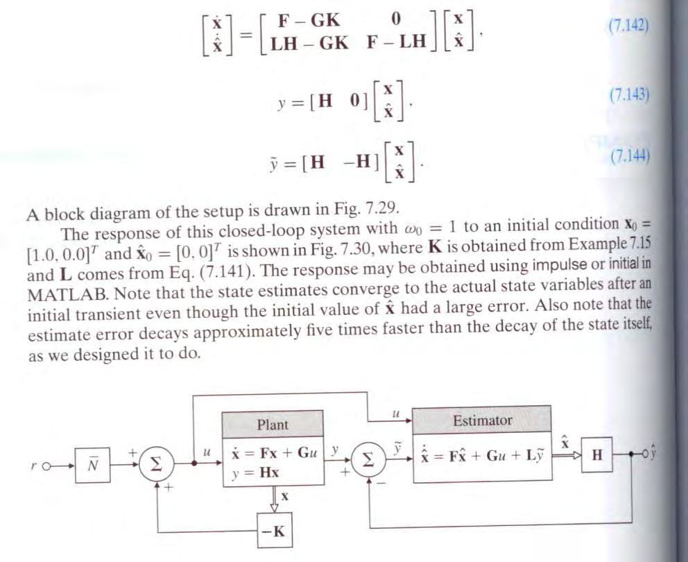
11 Regulator with estimated states Plant: Control law: Estimator:

12 State equations for closed-loop system Plant: Estimator: Control law: Combining these equations: Thus the closed-loop state equations are:

13 State equations for closed-loop system These equations may also be written in terms of the estimation error We had: Subtracting: Substituting in the first equation yields: With this alternative set of state variables the closed-loop system equations are:
14 State equations for closed-loop system The closed-loop characteristic polynomial is thus: which is block triangular. Hence: Thus, the poles of the CL system consist of the poles obtained by full state feedback through K, together with the estimator poles determined by the selection of L That is, the control law and the estimator can be designed independently of each other Separation Principle

15 Ex: regulation of water level in two-tank system The system can be described For
16 Ex: regulation of water level in two-tank system Specs: Required closed-loop time constants are 1 = 0.2 s, 2 = 0.05 s; i.e., desired CL char. poly is Control law: Demonstrate Ackermann's formula:
17 Ex: regulation of water level in two-tank system Estimator: Try estim. poles = 2 x controller poles; i.e., desired CL char. poly is α = (s +10)(s + 40) = s s Demonstrate Ackermann's formula:
18 Ex: regulation of water level in two-tank system Complete system Equivalent feedback compensator: Transfer function for compensator:
19 Example 7.25
20
21
22
23 Reduced-order estimators In the examples so far, we have estimated all the states In the situation where we can measure some of the states directly, we do not need to reconstruct them in an estimator note, however, that if the measurements are noisy, a full-state estimator will smooth these data, as well as reconstruct the unmeasured states If the measurements are reliable, then a reduced order estimator will be more accurate, because some of its outputs will be direct measurements A reduced-order estimator will be of lower order, thus requiring less computational power

24 Reduced-order estimators Plant model: possibly multiple measurements Partition states into measured x a and estimated x b That is:
25 Reduced-order estimators Hence, observer: Now, is in principle known, but derivative term is a problem: difficult to realize So, introduce a change in variable:
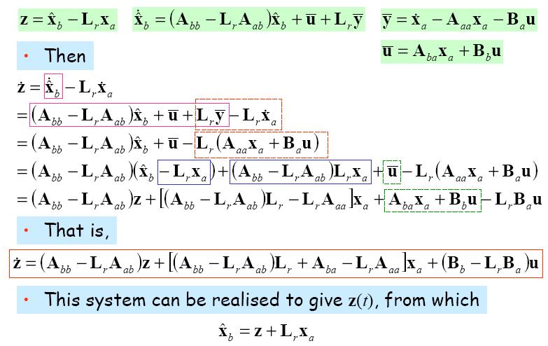
26 Reduced-order estimators
27 Error dynamics Estimation error That is, Hence, design L r as before, by selecting poles for A bb LrA ab Design: Lr = place(a_bb, A_ab, dep)
28 Example 7.26
29
30
31 Selection of estimator poles CL char. poly: The estimator poles (roots of a L (s) = 0) are usually chosen to be between 2 to 6 times faster than the controller poles (roots of a K (s) = 0) Clearly there is no direct effect of choosing faster estimator poles on control effort. However, consider the effect of sensor noise. Assume that the sensed output is error dynamics then become:. The estimation Thus, the higher estimator gains required to produce faster estimator dynamics will further amplify the sensor noise, thereby corrupting the state estimates

32 Symmetric root locus for SISO system estimator Estimator dynamics with 'process noise' w and 'sensor noise' v : The process noise w can represent unknown disturbances and errors in the plant model parameters Recall the estimator equations: If w is large: our plant model is uncertain, and hence a poor predictor we would put greater emphasis on the sensor data to correct the model predictions larger L, faster estimator poles If v is large: our measurements are uncertain, and hence provide poor corrections we would put greater emphasis on the model predictions smaller L, slower estimator poles
33 Symmetric root locus for SISO system estimator In optimal estimation theory the process noise is modeled as white noise with variance the sensor noise is modeled as white noise with variance The estimator pole locations which will minimize the variance of the state estimation error can be found from the solution of the symmetric root locus (SRL) equation: where is a measure of the plant model uncertainty relative to the measurement uncertainty, and is the plant transfer function from the process noise input to the measured output If the process noise w and control input u are additive (Bw = B), the same SRL can be used for controller and estimator pole selection
Advanced Control Theory
 State Feedback Control Design chibum@seoultech.ac.kr Outline State feedback control design Benefits of CCF 2 Conceptual steps in controller design We begin by considering the regulation problem the task
Control Systems. Design of State Feedback Control.
 Control Systems Design of State Feedback Control chibum@seoultech.ac.kr Outline Design of State feedback control Dominant pole design Symmetric root locus (linear quadratic regulation) 2 Selection of closed-loop
Here represents the impulse (or delta) function. is an diagonal matrix of intensities, and is an diagonal matrix of intensities.
 function. is an diagonal matrix of intensities, and is an diagonal matrix of intensities.") 19 KALMAN FILTER 19.1 Introduction In the previous section, we derived the linear quadratic regulator as an optimal solution for the fullstate feedback control problem. The inherent assumption was that
19 KALMAN FILTER 19.1 Introduction In the previous section, we derived the linear quadratic regulator as an optimal solution for the fullstate feedback control problem. The inherent assumption was that
CBE507 LECTURE III Controller Design Using State-space Methods. Professor Dae Ryook Yang
 CBE507 LECTURE III Controller Design Using State-space Methods Professor Dae Ryook Yang Fall 2013 Dept. of Chemical and Biological Engineering Korea University Korea University III -1 Overview States What
Separation Principle & Full-Order Observer Design
 Separation Principle & Full-Order Observer Design Suppose you want to design a feedback controller. Using full-state feedback you can place the poles of the closed-loop system at will. U Plant Kx If the
CHAPTER 4 STATE FEEDBACK AND OUTPUT FEEDBACK CONTROLLERS
 54 CHAPTER 4 STATE FEEDBACK AND OUTPUT FEEDBACK CONTROLLERS 4.1 INTRODUCTION In control theory, a controller is a device which monitors and affects the operational conditions of a given dynamic system.
State Observers and the Kalman filter
 Modelling and Control of Dynamic Systems State Observers and the Kalman filter Prof. Oreste S. Bursi University of Trento Page 1 Feedback System State variable feedback system: Control feedback law:u =
Linear State Feedback Controller Design
 Assignment For EE5101 - Linear Systems Sem I AY2010/2011 Linear State Feedback Controller Design Phang Swee King A0033585A Email: king@nus.edu.sg NGS/ECE Dept. Faculty of Engineering National University
CDS 101/110a: Lecture 8-1 Frequency Domain Design
 CDS 11/11a: Lecture 8-1 Frequency Domain Design Richard M. Murray 17 November 28 Goals: Describe canonical control design problem and standard performance measures Show how to use loop shaping to achieve
10/8/2015. Control Design. Pole-placement by state-space methods. Process to be controlled. State controller
 Pole-placement by state-space methods Control Design To be considered in controller design * Compensate the effect of load disturbances * Reduce the effect of measurement noise * Setpoint following (target
Chap 8. State Feedback and State Estimators
 Chap 8. State Feedback and State Estimators Outlines Introduction State feedback Regulation and tracking State estimator Feedback from estimated states State feedback-multivariable case State estimators-multivariable
Lecture 12. Upcoming labs: Final Exam on 12/21/2015 (Monday)10:30-12:30
10:30-12:30") 289 Upcoming labs: Lecture 12 Lab 20: Internal model control (finish up) Lab 22: Force or Torque control experiments [Integrative] (2-3 sessions) Final Exam on 12/21/2015 (Monday)10:30-12:30 Today: Recap
289 Upcoming labs: Lecture 12 Lab 20: Internal model control (finish up) Lab 22: Force or Torque control experiments [Integrative] (2-3 sessions) Final Exam on 12/21/2015 (Monday)10:30-12:30 Today: Recap
I. D. Landau, A. Karimi: A Course on Adaptive Control Adaptive Control. Part 9: Adaptive Control with Multiple Models and Switching
 I. D. Landau, A. Karimi: A Course on Adaptive Control - 5 1 Adaptive Control Part 9: Adaptive Control with Multiple Models and Switching I. D. Landau, A. Karimi: A Course on Adaptive Control - 5 2 Outline
MODERN CONTROL DESIGN
 CHAPTER 8 MODERN CONTROL DESIGN The classical design techniques of Chapters 6 and 7 are based on the root-locus and frequency response that utilize only the plant output for feedback with a dynamic controller
PID Control. Objectives
 PID Control Objectives The objective of this lab is to study basic design issues for proportional-integral-derivative control laws. Emphasis is placed on transient responses and steady-state errors. The
Topic # Feedback Control Systems
 Topic #15 16.31 Feedback Control Systems State-Space Systems Open-loop Estimators Closed-loop Estimators Observer Theory (no noise) Luenberger IEEE TAC Vol 16, No. 6, pp. 596 602, December 1971. Estimation
Pole placement control: state space and polynomial approaches Lecture 2
 : state space and polynomial approaches Lecture 2 : a state O. Sename 1 1 Gipsa-lab, CNRS-INPG, FRANCE Olivier.Sename@gipsa-lab.fr www.gipsa-lab.fr/ o.sename -based November 21, 2017 Outline : a state
Full State Feedback for State Space Approach
 Full State Feedback for State Space Approach State Space Equations Using Cramer s rule it can be shown that the characteristic equation of the system is : det[ si A] 0 Roots (for s) of the resulting polynomial
EL 625 Lecture 10. Pole Placement and Observer Design. ẋ = Ax (1)
") EL 625 Lecture 0 EL 625 Lecture 0 Pole Placement and Observer Design Pole Placement Consider the system ẋ Ax () The solution to this system is x(t) e At x(0) (2) If the eigenvalues of A all lie in the
EL 625 Lecture 0 EL 625 Lecture 0 Pole Placement and Observer Design Pole Placement Consider the system ẋ Ax () The solution to this system is x(t) e At x(0) (2) If the eigenvalues of A all lie in the
Control Systems Design, SC4026. SC4026 Fall 2010, dr. A. Abate, DCSC, TU Delft
 Control Systems Design, SC426 SC426 Fall 2, dr A Abate, DCSC, TU Delft Lecture 5 Controllable Canonical and Observable Canonical Forms Stabilization by State Feedback State Estimation, Observer Design
4 Arithmetic of Feedback Loops
 ME 132, Spring 2005, UC Berkeley, A. Packard 18 4 Arithmetic of Feedback Loops Many important guiding principles of feedback control systems can be derived from the arithmetic relations, along with their
Module 9: State Feedback Control Design Lecture Note 1
 Module 9: State Feedback Control Design Lecture Note 1 The design techniques described in the preceding lectures are based on the transfer function of a system. In this lecture we would discuss the state
Analysis and Synthesis of Single-Input Single-Output Control Systems
 Lino Guzzella Analysis and Synthesis of Single-Input Single-Output Control Systems l+kja» \Uja>)W2(ja»\ um Contents 1 Definitions and Problem Formulations 1 1.1 Introduction 1 1.2 Definitions 1 1.2.1 Systems
Fall 線性系統 Linear Systems. Chapter 08 State Feedback & State Estimators (SISO) Feng-Li Lian. NTU-EE Sep07 Jan08
 Feng-Li Lian. NTU-EE Sep07 Jan08") Fall 2007 線性系統 Linear Systems Chapter 08 State Feedback & State Estimators (SISO) Feng-Li Lian NTU-EE Sep07 Jan08 Materials used in these lecture notes are adopted from Linear System Theory & Design, 3rd.
Fall 2007 線性系統 Linear Systems Chapter 08 State Feedback & State Estimators (SISO) Feng-Li Lian NTU-EE Sep07 Jan08 Materials used in these lecture notes are adopted from Linear System Theory & Design, 3rd.
Mechanical Systems Part A: State-Space Systems Lecture AL12
 AL: 436-433 Mechanical Systems Part A: State-Space Systems Lecture AL Case study Case study AL: Design of a satellite attitude control system see Franklin, Powell & Emami-Naeini, Ch. 9. Requirements: accurate
Lecture 7 LQG Design. Linear Quadratic Gaussian regulator Control-estimation duality SRL for optimal estimator Example of LQG design for MIMO plant
 L7: Lecture 7 LQG Design Linear Quadratic Gaussian regulator Control-estimation duality SRL for optimal estimator Example of LQG design for IO plant LQG regulator L7:2 If the process and measurement noises
D(s) G(s) A control system design definition
 G(s) A control system design definition") R E Compensation D(s) U Plant G(s) Y Figure 7. A control system design definition x x x 2 x 2 U 2 s s 7 2 Y Figure 7.2 A block diagram representing Eq. (7.) in control form z U 2 s z Y 4 z 2 s z 2 3 Figure
R E Compensation D(s) U Plant G(s) Y Figure 7. A control system design definition x x x 2 x 2 U 2 s s 7 2 Y Figure 7.2 A block diagram representing Eq. (7.) in control form z U 2 s z Y 4 z 2 s z 2 3 Figure
Chapter 9 Observers, Model-based Controllers 9. Introduction In here we deal with the general case where only a subset of the states, or linear combin
 Lectures on Dynamic Systems and Control Mohammed Dahleh Munther A. Dahleh George Verghese Department of Electrical Engineering and Computer Science Massachuasetts Institute of Technology c Chapter 9 Observers,
Topic # Feedback Control. State-Space Systems Closed-loop control using estimators and regulators. Dynamics output feedback
 Topic #17 16.31 Feedback Control State-Space Systems Closed-loop control using estimators and regulators. Dynamics output feedback Back to reality Copyright 21 by Jonathan How. All Rights reserved 1 Fall
Feedback Control of Linear SISO systems. Process Dynamics and Control
 Feedback Control of Linear SISO systems Process Dynamics and Control 1 Open-Loop Process The study of dynamics was limited to open-loop systems Observe process behavior as a result of specific input signals
Synthesis via State Space Methods
 Chapter 18 Synthesis via State Space Methods Here, we will give a state space interpretation to many of the results described earlier. In a sense, this will duplicate the earlier work. Our reason for doing
The output voltage is given by,
 71 The output voltage is given by, = (3.1) The inductor and capacitor values of the Boost converter are derived by having the same assumption as that of the Buck converter. Now the critical value of the
Chapter 3. State Feedback - Pole Placement. Motivation
 Chapter 3 State Feedback - Pole Placement Motivation Whereas classical control theory is based on output feedback, this course mainly deals with control system design by state feedback. This model-based
Control System Design
 ELEC ENG 4CL4: Control System Design Notes for Lecture #36 Dr. Ian C. Bruce Room: CRL-229 Phone ext.: 26984 Email: ibruce@mail.ece.mcmaster.ca Friday, April 4, 2003 3. Cascade Control Next we turn to an
Controls Problems for Qualifying Exam - Spring 2014
 Controls Problems for Qualifying Exam - Spring 2014 Problem 1 Consider the system block diagram given in Figure 1. Find the overall transfer function T(s) = C(s)/R(s). Note that this transfer function
Control Systems Design
 ELEC4410 Control Systems Design Lecture 18: State Feedback Tracking and State Estimation Julio H. Braslavsky julio@ee.newcastle.edu.au School of Electrical Engineering and Computer Science Lecture 18:
State Regulator. Advanced Control. design of controllers using pole placement and LQ design rules
 Advanced Control State Regulator Scope design of controllers using pole placement and LQ design rules Keywords pole placement, optimal control, LQ regulator, weighting matrixes Prerequisites Contact state
Control System Design
 ELEC4410 Control System Design Lecture 19: Feedback from Estimated States and Discrete-Time Control Design Julio H. Braslavsky julio@ee.newcastle.edu.au School of Electrical Engineering and Computer Science
A FEEDBACK STRUCTURE WITH HIGHER ORDER DERIVATIVES IN REGULATOR. Ryszard Gessing
 A FEEDBACK STRUCTURE WITH HIGHER ORDER DERIVATIVES IN REGULATOR Ryszard Gessing Politechnika Śl aska Instytut Automatyki, ul. Akademicka 16, 44-101 Gliwice, Poland, fax: +4832 372127, email: gessing@ia.gliwice.edu.pl
Chapter 6 State-Space Design
 Chapter 6 State-Space Design wo steps. Assumption is made that we have all the states at our disposal for feedback purposes (in practice, we would not measure all these states). his allows us to implement
Chapter 7 - Solved Problems
 Chapter 7 - Solved Problems Solved Problem 7.1. A continuous time system has transfer function G o (s) given by G o (s) = B o(s) A o (s) = 2 (s 1)(s + 2) = 2 s 2 + s 2 (1) Find a controller of minimal
Motor Controller. A block diagram for the motor with a feedback controller is shown below
 Motor Controller A block diagram for the motor with a feedback controller is shown below A few things to note 1. In this modeling problem, there is no established method or set of criteria for selecting
6.302 Feedback Systems Recitation 16: Compensation Prof. Joel L. Dawson
 Bode Obstacle Course is one technique for doing compensation, or designing a feedback system to make the closed-loop behavior what we want it to be. To review: - G c (s) G(s) H(s) you are here! plant For
Unit 8: Part 2: PD, PID, and Feedback Compensation
 Ideal Derivative Compensation (PD) Lead Compensation PID Controller Design Feedback Compensation Physical Realization of Compensation Unit 8: Part 2: PD, PID, and Feedback Compensation Engineering 5821:
1 An Overview and Brief History of Feedback Control 1. 2 Dynamic Models 23. Contents. Preface. xiii
 Contents 1 An Overview and Brief History of Feedback Control 1 A Perspective on Feedback Control 1 Chapter Overview 2 1.1 A Simple Feedback System 3 1.2 A First Analysis of Feedback 6 1.3 Feedback System
Review: stability; Routh Hurwitz criterion Today s topic: basic properties and benefits of feedback control
 Plan of the Lecture Review: stability; Routh Hurwitz criterion Today s topic: basic properties and benefits of feedback control Goal: understand the difference between open-loop and closed-loop (feedback)
Control Design. Lecture 9: State Feedback and Observers. Two Classes of Control Problems. State Feedback: Problem Formulation
 Lecture 9: State Feedback and s [IFAC PB Ch 9] State Feedback s Disturbance Estimation & Integral Action Control Design Many factors to consider, for example: Attenuation of load disturbances Reduction
Internal Model Control of A Class of Continuous Linear Underactuated Systems
 Internal Model Control of A Class of Continuous Linear Underactuated Systems Asma Mezzi Tunis El Manar University, Automatic Control Research Laboratory, LA.R.A, National Engineering School of Tunis (ENIT),
MASSACHUSETTS INSTITUTE OF TECHNOLOGY Department of Mechanical Engineering 2.04A Systems and Controls Spring 2013
 MASSACHUSETTS INSTITUTE OF TECHNOLOGY Department of Mechanical Engineering 2.04A Systems and Controls Spring 2013 Problem Set #4 Posted: Thursday, Mar. 7, 13 Due: Thursday, Mar. 14, 13 1. Sketch the Root
Plan of the Lecture. Review: stability; Routh Hurwitz criterion Today s topic: basic properties and benefits of feedback control
 Plan of the Lecture Review: stability; Routh Hurwitz criterion Today s topic: basic properties and benefits of feedback control Plan of the Lecture Review: stability; Routh Hurwitz criterion Today s topic:
Dr Ian R. Manchester Dr Ian R. Manchester AMME 3500 : Review
 Week Date Content Notes 1 6 Mar Introduction 2 13 Mar Frequency Domain Modelling 3 20 Mar Transient Performance and the s-plane 4 27 Mar Block Diagrams Assign 1 Due 5 3 Apr Feedback System Characteristics
Chapter 9 Robust Stability in SISO Systems 9. Introduction There are many reasons to use feedback control. As we have seen earlier, with the help of a
 Lectures on Dynamic Systems and Control Mohammed Dahleh Munther A. Dahleh George Verghese Department of Electrical Engineering and Computer Science Massachuasetts Institute of Technology c Chapter 9 Robust
Inverted Pendulum: State-Space Methods for Controller Design
 1 de 12 18/10/2015 22:45 Tips Effects TIPS ABOUT BASICS HARDWARE INDEX NEXT INTRODUCTION CRUISE CONTROL MOTOR SPEED MOTOR POSITION SYSTEM MODELING ANALYSIS Inverted Pendulum: State-Space Methods for Controller
6.1 Sketch the z-domain root locus and find the critical gain for the following systems K., the closed-loop characteristic equation is K + z 0.
 6. Sketch the z-domain root locus and find the critical gain for the following systems K (i) Gz () z 4. (ii) Gz K () ( z+ 9. )( z 9. ) (iii) Gz () Kz ( z. )( z ) (iv) Gz () Kz ( + 9. ) ( z. )( z 8. ) (i)
Advanced Control Theory
 State Space Solution and Realization chibum@seoultech.ac.kr Outline State space solution 2 Solution of state-space equations x t = Ax t + Bu t First, recall results for scalar equation: x t = a x t + b
Root Locus. Motivation Sketching Root Locus Examples. School of Mechanical Engineering Purdue University. ME375 Root Locus - 1
 Root Locus Motivation Sketching Root Locus Examples ME375 Root Locus - 1 Servo Table Example DC Motor Position Control The block diagram for position control of the servo table is given by: D 0.09 Position
EEE582 Homework Problems
 EEE582 Homework Problems HW. Write a state-space realization of the linearized model for the cruise control system around speeds v = 4 (Section.3, http://tsakalis.faculty.asu.edu/notes/models.pdf). Use
Problem Set 4 Solution 1
 Massachusetts Institute of Technology Department of Electrical Engineering and Computer Science 6.245: MULTIVARIABLE CONTROL SYSTEMS by A. Megretski Problem Set 4 Solution Problem 4. For the SISO feedback
EECS C128/ ME C134 Final Wed. Dec. 15, am. Closed book. Two pages of formula sheets. No calculators.
 Name: SID: EECS C28/ ME C34 Final Wed. Dec. 5, 2 8- am Closed book. Two pages of formula sheets. No calculators. There are 8 problems worth points total. Problem Points Score 2 2 6 3 4 4 5 6 6 7 8 2 Total
RELAY CONTROL WITH PARALLEL COMPENSATOR FOR NONMINIMUM PHASE PLANTS. Ryszard Gessing
 RELAY CONTROL WITH PARALLEL COMPENSATOR FOR NONMINIMUM PHASE PLANTS Ryszard Gessing Politechnika Śl aska Instytut Automatyki, ul. Akademicka 16, 44-101 Gliwice, Poland, fax: +4832 372127, email: gessing@ia.gliwice.edu.pl
Intro. Computer Control Systems: F9
 Intro. Computer Control Systems: F9 State-feedback control and observers Dave Zachariah Dept. Information Technology, Div. Systems and Control 1 / 21 dave.zachariah@it.uu.se F8: Quiz! 2 / 21 dave.zachariah@it.uu.se
4.0 Update Algorithms For Linear Closed-Loop Systems
 4. Update Algorithms For Linear Closed-Loop Systems A controller design methodology has been developed that combines an adaptive finite impulse response (FIR) filter with feedback. FIR filters are used
ECE317 : Feedback and Control
 ECE317 : Feedback and Control Lecture : Steady-state error Dr. Richard Tymerski Dept. of Electrical and Computer Engineering Portland State University 1 Course roadmap Modeling Analysis Design Laplace
Linear-Quadratic-Gaussian Controllers!
 Linear-Quadratic-Gaussian Controllers! Robert Stengel! Optimal Control and Estimation MAE 546! Princeton University, 2017!! LTI dynamic system!! Certainty Equivalence and the Separation Theorem!! Asymptotic
5. Observer-based Controller Design
 EE635 - Control System Theory 5. Observer-based Controller Design Jitkomut Songsiri state feedback pole-placement design regulation and tracking state observer feedback observer design LQR and LQG 5-1
Outline. Classical Control. Lecture 1
 Outline Outline Outline 1 Introduction 2 Prerequisites Block diagram for system modeling Modeling Mechanical Electrical Outline Introduction Background Basic Systems Models/Transfers functions 1 Introduction
MIMO analysis: loop-at-a-time
 MIMO robustness MIMO analysis: loop-at-a-time y 1 y 2 P (s) + + K 2 (s) r 1 r 2 K 1 (s) Plant: P (s) = 1 s 2 + α 2 s α 2 α(s + 1) α(s + 1) s α 2. (take α = 10 in the following numerical analysis) Controller:
Control Systems I. Lecture 2: Modeling. Suggested Readings: Åström & Murray Ch. 2-3, Guzzella Ch Emilio Frazzoli
 Control Systems I Lecture 2: Modeling Suggested Readings: Åström & Murray Ch. 2-3, Guzzella Ch. 2-3 Emilio Frazzoli Institute for Dynamic Systems and Control D-MAVT ETH Zürich September 29, 2017 E. Frazzoli
Today (10/23/01) Today. Reading Assignment: 6.3. Gain/phase margin lead/lag compensator Ref. 6.4, 6.7, 6.10
 Today. Reading Assignment: 6.3. Gain/phase margin lead/lag compensator Ref. 6.4, 6.7, 6.10") Today Today (10/23/01) Gain/phase margin lead/lag compensator Ref. 6.4, 6.7, 6.10 Reading Assignment: 6.3 Last Time In the last lecture, we discussed control design through shaping of the loop gain GK:
Today Today (10/23/01) Gain/phase margin lead/lag compensator Ref. 6.4, 6.7, 6.10 Reading Assignment: 6.3 Last Time In the last lecture, we discussed control design through shaping of the loop gain GK:
Chapter 5. Standard LTI Feedback Optimization Setup. 5.1 The Canonical Setup
 Chapter 5 Standard LTI Feedback Optimization Setup Efficient LTI feedback optimization algorithms comprise a major component of modern feedback design approach: application problems involving complex models
Stability of CL System
 Stability of CL System Consider an open loop stable system that becomes unstable with large gain: At the point of instability, K( j) G( j) = 1 0dB K( j) G( j) K( j) G( j) K( j) G( j) =± 180 o 180 o Closed
SECTION 2: BLOCK DIAGRAMS & SIGNAL FLOW GRAPHS
 SECTION 2: BLOCK DIAGRAMS & SIGNAL FLOW GRAPHS MAE 4421 Control of Aerospace & Mechanical Systems 2 Block Diagram Manipulation Block Diagrams 3 In the introductory section we saw examples of block diagrams
Linear Control Systems
 Linear Control Systems Project session 3: Design in state-space 6 th October 2017 Kathleen Coutisse kathleen.coutisse@student.ulg.ac.be 1 Content 1. Closed loop system 2. State feedback 3. Observer 4.
Dynamics and control of mechanical systems
 Dynamics and control of mechanical systems Date Day 1 (03/05) - 05/05 Day 2 (07/05) Day 3 (09/05) Day 4 (11/05) Day 5 (14/05) Day 6 (16/05) Content Review of the basics of mechanics. Kinematics of rigid
Meeting Design Specs using Root Locus
 Meeting Design Specs using Root Locus So far, we have Lead compensators which cancel a pole and move it left, speeding up the root locus. PID compensators which add a zero at s=0 and add zero, one, or
Video 5.1 Vijay Kumar and Ani Hsieh
 Video 5.1 Vijay Kumar and Ani Hsieh Robo3x-1.1 1 The Purpose of Control Input/Stimulus/ Disturbance System or Plant Output/ Response Understand the Black Box Evaluate the Performance Change the Behavior
Online monitoring of MPC disturbance models using closed-loop data
 Online monitoring of MPC disturbance models using closed-loop data Brian J. Odelson and James B. Rawlings Department of Chemical Engineering University of Wisconsin-Madison Online Optimization Based Identification
Dynamic Compensation using root locus method
 CAIRO UNIVERSITY FACULTY OF ENGINEERING ELECTRONICS & COMMUNICATIONS DEP. 3rd YEAR, 00/0 CONTROL ENGINEERING SHEET 9 Dynamic Compensation using root locus method [] (Final00)For the system shown in the
Chap 4. State-Space Solutions and
 Chap 4. State-Space Solutions and Realizations Outlines 1. Introduction 2. Solution of LTI State Equation 3. Equivalent State Equations 4. Realizations 5. Solution of Linear Time-Varying (LTV) Equations
Fundamental Design Limitations of the General Control Configuration
 IEEE TRANSACTIONS ON AUTOMATIC CONTROL, VOL 48, NO 8, AUGUST 2003 1355 Fundamental Design Limitations of the General Control Configuration Jim S Freudenberg, Fellow, IEEE, C V Hollot, Senior Member, IEEE,
9. Two-Degrees-of-Freedom Design
 9. Two-Degrees-of-Freedom Design In some feedback schemes we have additional degrees-offreedom outside the feedback path. For example, feed forwarding known disturbance signals or reference signals. In
Video 6.1 Vijay Kumar and Ani Hsieh
 Video 6.1 Vijay Kumar and Ani Hsieh Robo3x-1.6 1 In General Disturbance Input + - Input Controller + + System Output Robo3x-1.6 2 Learning Objectives for this Week State Space Notation Modeling in the
Let the plant and controller be described as:-
 Summary of Fundamental Limitations in Feedback Design (LTI SISO Systems) From Chapter 6 of A FIRST GRADUATE COURSE IN FEEDBACK CONTROL By J. S. Freudenberg (Winter 2008) Prepared by: Hammad Munawar (Institute
Chapter 15 - Solved Problems
 Chapter 5 - Solved Problems Solved Problem 5.. Contributed by - Alvaro Liendo, Universidad Tecnica Federico Santa Maria, Consider a plant having a nominal model given by G o (s) = s + 2 The aim of the
Design Methods for Control Systems
 Design Methods for Control Systems Maarten Steinbuch TU/e Gjerrit Meinsma UT Dutch Institute of Systems and Control Winter term 2002-2003 Schedule November 25 MSt December 2 MSt Homework # 1 December 9
Contents. PART I METHODS AND CONCEPTS 2. Transfer Function Approach Frequency Domain Representations... 42
 Contents Preface.............................................. xiii 1. Introduction......................................... 1 1.1 Continuous and Discrete Control Systems................. 4 1.2 Open-Loop
Professional Portfolio Selection Techniques: From Markowitz to Innovative Engineering
 Massachusetts Institute of Technology Sponsor: Electrical Engineering and Computer Science Cosponsor: Science Engineering and Business Club Professional Portfolio Selection Techniques: From Markowitz to
 Department of Electronics and Instrumentation Engineering M. E- CONTROL AND INSTRUMENTATION ENGINEERING CL7101 CONTROL SYSTEM DESIGN Unit I- BASICS AND ROOT-LOCUS DESIGN PART-A (2 marks) 1. What are the
Pole Placement (Bass Gura)
") Definition: Open-Loop System: System dynamics with U =. sx = AX Closed-Loop System: System dynamics with U = -Kx X sx = (A BK x )X Characteristic Polynomial: Pole Placement (Bass Gura) a) The polynomial
Definition: Open-Loop System: System dynamics with U =. sx = AX Closed-Loop System: System dynamics with U = -Kx X sx = (A BK x )X Characteristic Polynomial: Pole Placement (Bass Gura) a) The polynomial
Design of Nonlinear Control Systems with the Highest Derivative in Feedback
 SERIES ON STAB1UTY, VIBRATION AND CONTROL OF SYSTEMS SeriesA Volume 16 Founder & Editor: Ardeshir Guran Co-Editors: M. Cloud & W. B. Zimmerman Design of Nonlinear Control Systems with the Highest Derivative
Introduction to Feedback Control
 Introduction to Feedback Control Control System Design Why Control? Open-Loop vs Closed-Loop (Feedback) Why Use Feedback Control? Closed-Loop Control System Structure Elements of a Feedback Control System
Pitch Rate CAS Design Project
 Pitch Rate CAS Design Project Washington University in St. Louis MAE 433 Control Systems Bob Rowe 4.4.7 Design Project Part 2 This is the second part of an ongoing project to design a control and stability
Lecture 18 : State Space Design
 UCSI University Kuala Lumpur, Malaysia Faculty of Engineering Department of Mechatronics Lecture 18 State Space Design Mohd Sulhi bin Azman Lecturer Department of Mechatronics UCSI University sulhi@ucsi.edu.my
Contrôle de position ultra-rapide d un objet nanométrique
 Contrôle de position ultra-rapide d un objet nanométrique présenté par Alina VODA alina.voda@gipsa-lab.grenoble-inp.fr sur la base de la thèse de Irfan AHMAD, co-encadrée avec Gildas BESANCON plate-forme
Multi-Input Multi-output (MIMO) Processes CBE495 LECTURE III CONTROL OF MULTI INPUT MULTI OUTPUT PROCESSES. Professor Dae Ryook Yang
 Processes CBE495 LECTURE III CONTROL OF MULTI INPUT MULTI OUTPUT PROCESSES. Professor Dae Ryook Yang") Multi-Input Multi-output (MIMO) Processes CBE495 LECTURE III CONTROL OF MULTI INPUT MULTI OUTPUT PROCESSES Professor Dae Ryook Yang Fall 2013 Dept. of Chemical and Biological Engineering Korea University
Multi-Input Multi-output (MIMO) Processes CBE495 LECTURE III CONTROL OF MULTI INPUT MULTI OUTPUT PROCESSES Professor Dae Ryook Yang Fall 2013 Dept. of Chemical and Biological Engineering Korea University
OPTIMAL CONTROL AND ESTIMATION
 OPTIMAL CONTROL AND ESTIMATION Robert F. Stengel Department of Mechanical and Aerospace Engineering Princeton University, Princeton, New Jersey DOVER PUBLICATIONS, INC. New York CONTENTS 1. INTRODUCTION
CONTROL SYSTEMS, ROBOTICS, AND AUTOMATION Vol. III Controller Design - Boris Lohmann
 CONROL SYSEMS, ROBOICS, AND AUOMAION Vol. III Controller Design - Boris Lohmann CONROLLER DESIGN Boris Lohmann Institut für Automatisierungstechnik, Universität Bremen, Germany Keywords: State Feedback
Control System Design
 ELEC ENG 4CL4: Control System Design Notes for Lecture #11 Wednesday, January 28, 2004 Dr. Ian C. Bruce Room: CRL-229 Phone ext.: 26984 Email: ibruce@mail.ece.mcmaster.ca Relative Stability: Stability
State Feedback and State Estimators Linear System Theory and Design, Chapter 8.
 1 Linear System Theory and Design, http://zitompul.wordpress.com 2 0 1 4 2 Homework 7: State Estimators (a) For the same system as discussed in previous slides, design another closed-loop state estimator,
Control of MIMO processes. 1. Introduction. Control of MIMO processes. Control of Multiple-Input, Multiple Output (MIMO) Processes
 Processes") Control of MIMO processes Control of Multiple-Input, Multiple Output (MIMO) Processes Statistical Process Control Feedforward and ratio control Cascade control Split range and selective control Control
Control of MIMO processes Control of Multiple-Input, Multiple Output (MIMO) Processes Statistical Process Control Feedforward and ratio control Cascade control Split range and selective control Control