Teton Dam Failure A Review of the Technical Factors Contributing to the Failure
|
|
|
- Michael Grant
- 5 years ago
- Views:
Transcription


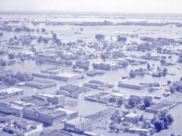
1 Teton Dam Failure A Review of the Technical Factors Contributing to the Failure
2
3 Outline of Presentation Location, Background and Project Statistics Technical Causes of Failure to be Discussed Geology Embankment Design and Materials Test Grout Program and the Abutment Cutoff Trench Design Decision Foundation Design and Construction Embankment Construction First filling Initial signs of seepage
4 Outline of Presentation Failure Mode description of each step with photos, sketches, detailed interpretation of what is going on inside using the new 3D model forensic investigations / construction photos / analysis to describe the failure mode Review of Technical Causes of Failure Lessons Learned

5 Location Map Teton Dam

6 Background Studies for a water storage site in the area date back to the 1930s Site clearing began in 1972; the embankment was completed by First filling was spring of 1976 Dam failed catastrophically on June 5, 1976
7 Project Statistics Height 305 feet (above river bed) Structural height over 400 ft (above foundation rock) Crest length 3,100 feet Base width 1,700 feet Zoned earthfill with about 10 million cubic yards Gated chute spillway on right abutment with 3 gates Outlet works through tunnel in left abutment Reservoir volume at failure 250,000 ac-ft at El Reservoir length ~ 20 miles
8 Technical Causes of Failure Discussed in this Presentation Role of geologic formations erodible soil and open jointed rock Steep core trench and stress arching Hydraulic fracture potential Rapid filling Design basis Reliance on grouting and special compaction in key trench Lack of foundation surface treatment in key trench Lack of defensive seepage control measures
9 Contributors to the failure not discussed in this Presentation Lessons not learned from the near-failure of Reclamation s Fontenelle Dam in 1965 Lack of external design review (CRB) Organizational structure (design/construction) and conflicts between offices Lack of communication between Design and Construction parts of the organization Cost pressures (cost cutting culture; cost/benefit pressures) Lack of interaction between geologists and design engineers Role of wet seam in the failure (from forensics)
10 Regional Geology Map Text Teton Dam

11 Regional Geology Map Text Teton Dam

12 Pre-construction site Aeolian sediments on plateau are about 30 ft. thick Alluvium deposited in channel about 100 ft. thick
13 Site Geology
14 Site Geology
15 Site Geology
16 Site Geology
17 Site Geology
18 Site Geology Terms welded ash flow tuff and rhyolite are used interchangeably in Teton reports


19 Site Geology Terms welded ash flow tuff and rhyolite are used interchangeably in Teton reports

20 Current Site Geology Huckleberry Ridge Tuff welded rhyolitic ash flow tuff erupted from the Henry s Fork caldera of the Yellowstone plateau

21 Current Site Geology

22 Current Site Geology
 Geologic mapping Pumping tests Groundwater observations Pilot grout program and follow up pressure")
23 Geologic Investigations Foundation exploration drilling program (many phases and drill holes ~ 20,000 ft.) Geologic mapping Pumping tests Groundwater observations Pilot grout program and follow up pressure testing
 Geologic mapping Pumping tests Groundwater observations Pilot grout program and follow up pressure")
24 Geologic Investigations Foundation exploration drilling program (many phases and drill holes ~ 20,000 ft.) Geologic mapping Pumping tests Groundwater observations Pilot grout program and follow up pressure testing

25 Geologic Investigations
26 Welded ash-flow tuff Unit 1 - uppermost lenticular and tabular plates or slabs, mostly 2 to 6 inches Openings between plates are ¼ to 2 inches, some filled with caliche and silt
27 Welded ash-flow tuff Unit 2 intermediate layer, high angle joints at 10 to 20 ft. intervals dominate Most joints open 1/8 to 1 inches and coated or filled with calcium carbonate

28 Welded ash-flow tuff Unit 3 lower layer Contact marked by breccia zone, 6 inches to 2 ft. thick Near vertical joints prominent, can be traced over 100 ft. Spacing 5 to 10 ft., with openings ¼ inch to 3 inches
29 Basalt Encountered beneath alluvium on the left side of the channel, but not the right. Exposed in foundation for power plant and other various outcrops Source of the basalt flow believed to be at the mouth of the Teton Canyon (d/s), and flowed up-canyon over a thin layer of alluvium covering the floor of the gorge to about elevation 5005 ft. River subsequently eroded the basalt from the right side, but it remained on the left side
30 Project Design Project designed by the Division of Design in the Engineering and Research Center of the Bureau of Reclamation located in Denver
31 Embankment Design Considerations What materials are available at the site? What type of embankment dam would be best suited for the site? (e.g. homogeneous, zoned earth, central core rockfill, etc.) How should the design address the problematic foundation geology that had been identified in the extensive site explorations?
32 Embankment Design What materials were available at the site? ML eolian silts covering the uplands (millions of cubic yards available nearby) GP and GW river deposits in the bottom of the Teton River canyon (quantities almost unlimited at the damsite) Basalt could be quarried from exposed remnants of the intraflow (large quantities, but requiring a 4-mile haul)
33 Embankment Design What type of embankment would be best suited for the site? Homogeneous ML embankment was considered; had the benefit of being an economical choice A zoned earthfill embankment was selected due to concerns about cracking: ML soils contained a high percentage of caliche Earthquake crack protection seismic zone 3
34 Embankment Design How should the design address the problematic foundation geology?

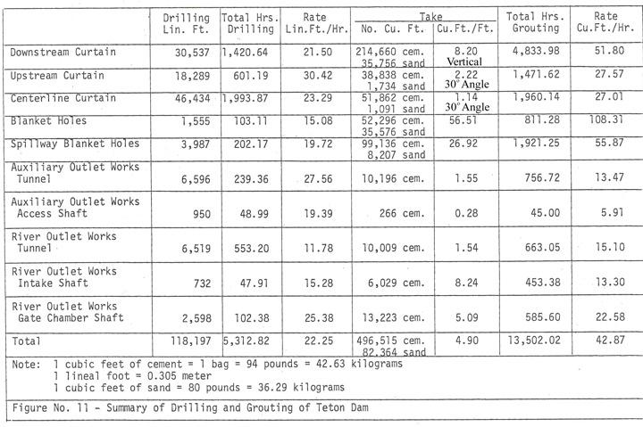
35 1969 Pilot Grouting Program Program consisted of drilling and grouting 23 holes There were significant takes in several holes Grout takes in 2 holes exceeded the amount estimated for the entire project over 15,000 sacks of cement and over 17,000 cu.ft. of sand. High takes at depths less than 70 feet Grouting the upper 30 feet of curtain holes was abandoned since the cutoff was expected to go at least that deep
36 Critical Design Decision: From review of drill logs and pilot grouting program, designers concluded it would be more economical to remove the upper 70 feet of the foundation than to conduct the grouting necessary to seal this rock A foundation key trench 70 ft. deep was provided above El 5100 in both abutments, to remove the more open jointed rock, and reach a groutable, more sound rock.

37 Critical Design Decision: There was no precedent for this design at Reclamation
38 Foundation Design By 1971 the foundation design philosophy was established The seepage barrier on the abutments was to consist of: 1. a 70 ft. deep key trench through the highly jointed rock on the abutments, and 2. a three-row grout curtain

39 Foundation Design To address cost concerns that the outer two rows of grout holes would accept extremely large quantities, and grout would travel large distances the grout quantities in the outer two rows were limited This resulted in a single row curtain installed through a central grout cap

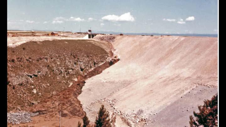
40 Foundation Design Right key trench
41 Foundation Design In the main channel, 100 feet of alluvial materials were excavated to rock Cofferdams and extensive dewatering used to protect the foundation work area

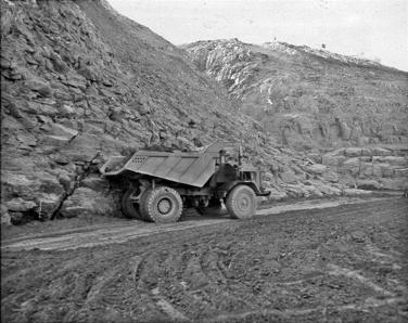
42 Embankment Design Zoned earthfill embankment with a thick central core Maximum height of 305 feet above the valley floor 405 feet above the lowest point excavated in the foundation
43 Embankment Design Key defensive design measures that were not included in the design: No transition zone between Zone 1 and the alluvium in the valley bottom No transition zone between Zone 1 and the fractured rock in the key trench, downstream of the grout cap No provisions for surface treatment (dental concrete or slush grouting) No drainage system was provided in either abutment No downstream piezometers or similar instruments were installed
44 Foundation Construction Curtain grouting two outer barrier rows and center grout cap row Special emphasis placed during construction on grouting 118,000 l.f. of grout holes Over 600,000 cf of cement, sand The design required blanket grouting only if required to treat specific defects Limited blanket grouting was done 1971 Design Considerations called for open joints and cracks to be treated by cleaning with air, sealing the surface, and low pressure grouting Drawings and specs did not include this requirement Little of this type of treatment was actually done Instead slurry concrete or slush grouting was performed
 grouting procedure The construction office")
45 Why not shotcrete the cutoff trench? After a site visit designers considered shotcreting the downstream face of the cutoff trench Construction office subsequently developed the bucket (slush) grouting procedure The construction office also agreed to put extra effort into special compaction in the cutoff trench No official documentation of these decisions Post-failure documentation in the IRG failure report
46 Slush Grouting Design specs did not include slush grouting or any other way to treat the Zone 1 / bedrock interface when open joints were exposed The construction office directed the placement of over 1800 cy. of slush grout Accomplished by simply pouring slurry into open joints by gravity flow Slush grouting discontinued above elevation 5205 because the joint size became too small to grout by


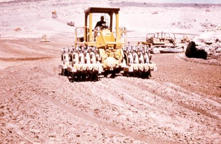
47 What is special compaction? Compaction of materials using special techniques, typically in thinner lifts with smaller hand operated equipment


48 Construction Fall of 1972 work began on the key trench mostly to the right of the spillway Some grout cap excavation completed Diversion tunnel construction


49 Construction Spring / summer right abutment key trench excavation continued starting to take shape Continued excavation of 100 feet of alluvium in the main channel between the cofferdams

50 Construction


51 Construction In the channel, difficult rock conditions were encountered, including vertical faces and overhangs Drilling and blasting was required to shape the rock


52 Construction These photos show how the rock was shaped at 0.5:1 slopes with drilling and blasting Foundation rock was cleaned Also, the grout cap was installed using steps in some places


53 Construction Excavation through 100 feet of alluvium in the main channel also presented dewatering challenges to the construction


54 Construction Throughout 1974, it became more apparent in the photo record that open joints, fissures, void were prevalent..
55 Construction - Grouting


56 Construction

57 Construction ~ 1975
58 Reservoir Filling Plan Flow through the river outlet works diversion tunnel (~2400 cfs capacity) would stop on October 1 of the last construction season Winter river flows would go through the auxiliary outlet works (~850 cfs capacity) Unless adverse performance develops, unrestricted filling rates will be permitted to elevation Above elevation 5200 initial filling should not exceed 1 foot per day.
59 Reservoir Filling October 3, 1975: River outlet works closed March 3, 1976: reservoir elevation 5170 (depth of 135 feet); average rate of rise had been approximately 0.2 ft./ day March 3, 1976: Construction Engineer requested a relaxation of the 1 ft./day filling rate due to heavy snowpack and high expected inflows The Denver Office granted this request, allowing 2 ft./day
60 Reservoir Filling Actual April through May 10, 1976: filling rate was no higher than 2 ft./day May 11 through June 5: the 2 ft./day requirement was exceeded - avg. daily rise of 3.0 feet, max. rise of 4.3 feet on May 18 (inflows ~4000 cfs) May 12 through June 5: the auxiliary outlet was discharging at a rate higher than its capacity of 850 cfs Inflow Outflow


61 Initial Seepage June 3 and 4 On June 3, project personnel inspecting the right abutment found two small seeps located 1,300 and 1,500 feet downstream from the toe of the dam On June 4, a small seep was found at the right abutment about 150 to 200 feet downstream from the toe of the dam

62 Initial Seepage June 3 and 4 June 3 seeps June 4 seep
63 Failure Mode Description Typical internal erosion event tree Reservoir at or above threshold level Initiation Erosion starts exists sidewalls Continuation Unfiltered or inadequately filtered exit Progression Continuous stable roof and/or fails to limit flows upstream zone Progression Constriction or upstream zone Progression No self-healing by Intervention fails Dam breaches

64 Evidence to support a focused analysis in the vicinity of Sta During construction: Numerous open joints visible in the key trench Large quantities of surface slush grout placed in open joints During failure: Location of sinkhole that formed briefly in advance of the erosion was at about Sta Upstream whirlpool was in the vicinity of Sta El ft. deep El El
65 Evidence to support a focused analysis in the vicinity of Sta Post-Failure Forensics: Key trench walls completed washed away in this area Grout cap missing between Sta and Sta Water testing of the grout curtain indicated shallow windows beneath the curtain Series of 3 open, transverse, vertical joints evident beneath the key trench Low stress zones in the Zone 1 embankment materials Stress analysis indicated that as early as May 25 (reservoir El. 5275), the hydrostatic pressure would have exceeded the total stress at the base of the key trench at Sta 14+00


66 Evidence to support a focused analysis in the vicinity of Sta Post-Failure Forensics: Key trench walls completed washed away in this area Grout cap missing between Sta and Sta Water testing of the grout curtain indicated shallow windows beneath the curtain Series of 3 open, transverse, vertical joints evident beneath the key trench Low stress zones in the Zone 1 embankment materials Stress analysis indicated that as early as May 25 (reservoir El. 5275), the hydrostatic pressure would have exceeded the total stress at the base of the key trench at Sta 14+00
67 Failure Mode Description Reservoir in first filling untested at all levels Reservoir at or above threshold level Initiation Erosion starts exists Continuation Unfiltered or inadequately filtered exit Progression Continuous stable roof fails to limit flows upstream zone Progression Constriction or upstream zone Progression No self-healing by Intervention fails Dam breaches
68 Reservoir at threshold level Approximate theoretical gradient at by date Date Estimated Gradient (30 ft width) Estimated Gradient (6 ft width) Feb first wetting 0 0 March May May June
69 Reservoir at threshold level Approximate theoretical gradient at by date Date Estimated Gradient (30 ft width) Estimated Gradient (6 ft width) Feb first wetting 0 0 March May May June
70 Failure Mode Description Initiation Reservoir at or above threshold level Initiation Erosion starts in right abutment key trench Continuation Open / unfiltered exit exists Progression Continuous stable roof fails to limit flows upstream zone Progression Constriction or upstream zone Progression No self-healing by Intervention fails Dam breaches
71 Initiation Starts in the Right Abutment Key Trench Garner and Fannin Venn Diagram illustrates that internal erosion initiates due to an unfavorable combination of: Material properties (easily erodible) Hydraulic conditions (leading to scour at the fnd contact) Stress conditions (leading to hydraulic fracture and scour above the contact)
 Achieving high density everywhere using special compaction methods is")
72 Initiation Starts in the Right Abutment Key Trench Material properties Loess soils uniformly graded and erodible Low Plasticity Index (single digits) Achieving high density everywhere using special compaction methods is unlikely
73 Initiation Starts in the Right Abutment Key Trench Hydraulic conditions Locally high gradients existed (early May - estimated 1.5 to over 4) Full reservoir head in open joint system Flow velocity through joints not sealed with slush grout and open windows in grout curtain allows scour at the Zone 1 / rock contact
74 Initiation Starts in the Right Abutment Key Trench Significant water passing through rock just beneath the grout cap, and possibly through the grout curtain at greater depth Concentration of through-going joints beneath and alongside the key trench Erodible fill within the key trench and in contact with the jointed rock downstream from the key trench
75 Initiation Starts in the Right Abutment Key Trench Larger cavities likely connected due to the high gradients to form a single erosion tunnel
76 Initiation Starts in the Right Abutment Key Trench Forensic evidence: Grout cap missing to 14+26

77 Initiation Starts in the Right Abutment Key Trench Forensic evidence: Grout cap missing to 14+26
78 Initiation Starts in the Right Abutment Key Trench Three prominent nearly vertical continuous joints crossing between Sta and (grout cap missing)
79 Initiation Starts in the Right Abutment Key Trench Three prominent nearly vertical continuous joints crossing between Sta and (grout cap missing)


80 Initiation Starts in the Right Abutment Key Trench 2-inch open fracture crossing the grout cap near Sta Erosion may have initiated at this set of open joints, or at other similar ones no longer there

81 Initiation Starts in the Right Abutment Key Trench Stress conditions Geometry of key trench favorable to arching multiple directions Static stress analysis performed by J.M. Duncan included in IP report as supporting evidence that low stresses existed and hydraulic fracturing may have occurred
82 Initiation Starts in the Right Abutment Key Trench First, second and third order arching Stress analyses modeled first order only with 2-D models 1 2 3
83 Initiation Starts in the Right Abutment Key Trench As early as May 20, the stress conditions could have allowed water to move both longitudinally and transversely in the vicinity of Sta 15+00
84 Initiation Starts in the Right Abutment Key Trench By June 5, the low stress area is over 200 ft in length (along profile) Low stress zone is above the bottom of open jointed rock
85 Initiation Starts in the Right Abutment Key Trench Role of grout curtain, grout cap, and open joints in the narrow key trench Direct scour of Zone 1 by flow through open joints Role of arching and low stress zones All three orders of arching were evident at Sta (cross sections, profiles, photographs) High degree of arching, combined with presence in this area of open transverse joints capable of delivering and carrying away large quantities of water, make cracking a highly probable potential cause of breaching the key trench fill
86 Initiation Starts in the Right Abutment Key Trench Physical conditions conducive to both possibilities There is strong evidence for both initiators: Scour along the base of the key trench Arching leading to low stress zones If the grout curtain was determined to be not effective, failure was most likely due to scour from underseepage If the grout curtain was determined to be fully effective, failure was most likely a result of hydraulic fracturing
87 Failure Mode Description Continuation open / unfiltered exit Reservoir at or above threshold level Initiation Erosion starts in right abutment key trench Continuation Open / unfiltered exit exists Progression Continuous stable roof fails to limit flows upstream zone Progression Constriction or upstream zone Progression No self-healing by Intervention fails Dam breaches
88 Continuation no filtered exit With no filter on the downstream slope of the key trench, Zone 1 materials were easily moved into the foundation rock joints The joint system downstream of the key trench likely served as the repository for eroded materials as flows found their way through the right abutment (continued for days or weeks) One breach, or multiple breaches across the key trench, occurred in the vicinity of Sta 14+00
89 Evidence of a Joint System Repository Slush grout surface treatment El 5200 contour Sta 14+00
90 Continuation no filtered exit In the upstream right abutment, the reservoir continued to rise and find more available pathways Eventually, as inflows continued to increase, and the downstream joint system was being infilled with Zone 1, the capacity of the downstream open joint system was exceeded by the flows With flow quantities increasing, and the flow capacity of the downstream rock mass being limited (joint size and infilling), the water needed another way out This was the beginning of a turning point in the failure mode
91 Erosion Pathways along Joints txt Key Trench CL Dam Axis Upstream Right Downstream Right
92 Erosion Pathways along Joints txt Key Trench CL Dam Axis Upstream Right Downstream Right

93 Erosion Pathways along Joints txt Key Trench CL Dam Axis Upstream Right Downstream Right
94 Erosion Pathways along Joints
95 Continuation no filtered exit
96 Continuation no filtered exit The large repository volume (open joints) in the vicinity of Sta to could have provided sufficient void space for seepage and eroded materials to go unnoticed for days Eyewitness accounts suggest that sometime overnight on June 4, seepage began to daylight, and damp areas were observed at the right groin On June 5 the flows increased and exited through talus, first at the groins at El 5045 and How much damage has been done before June 5?

97 Before June 5, how much damage do you think was done? text
98 Muddy flow from talus / slopewash 8:30 am June 5 Elevation 5045 (toe) cfs


99 Muddy flow from talus / slopewash 8:30 am June 5 Elevation 5045 (toe) cfs
100 Surface flows increasing ~10:15-10:30 am 15 cfs flow developed into a backwards progressing tunnel


101 Surface flows increasing ~10:15-10:30 am 15 cfs flow developed into a backwards progressing tunnel
102 Erosion Pathways along Joints txt
103 Erosion Pathways along Joints txt
104 Erosion Pathways along Joints txt
105 Erosion Pathways along Joints txt
106 Erosion Pathways along Joints txt

107 Erosion Pathways along Joints Approx. d/s limit Zone 1
108 Failure Mode Description Progression roof forms in the key trench Reservoir at or above threshold level Initiation Erosion starts in right abutment key trench Continuation Open / unfiltered exit exists Progression Continuous stable roof fails to limit flows upstream zone Progression Constriction or upstream zone Progression No self-healing by Intervention fails Dam breaches
109 Progression continuous stable roof forms in the key trench At first, the roof is across the steep, narrow key trench arching allows this to occur - possibly days before and completely through the failure mode progression Rock joints also serve as roof
110 Failure Mode Description Progression flows not limited Reservoir at or above threshold level Initiation Erosion starts in right abutment key trench Continuation Open / unfiltered exit exists Progression Continuous stable roof fails to limit flows upstream zone Progression Constriction or upstream zone Progression No self-healing by Intervention fails Dam breaches
111 Progression flows not limited Full reservoir head is provided to the key trench through the extensive system of open joints upstream of the core Flow through the embankment is not necessary therefore the embankment does nothing to limit flows
112 Failure Mode Description Progression no self healing by upstream zone Reservoir at or above threshold level Initiation Erosion starts in right abutment key trench Continuation Open / unfiltered exit exists Progression Continuous stable roof fails to limit flows upstream zone Progression Constriction or upstream zone Progression No self-healing by Intervention fails Dam breaches
113 Progression no self healing by upstream zone Since most of the flow is from the upstream open jointed rock, there is no opportunity to self heal the damage that is being done in the steep narrow key trench

114 Progression of erosion ~10:30-10:45 am Dozers sent to fill eroding hole
115 Progression of erosion ~10:45-11:00 am Dozers working downstream pushing riprap into hole (approx. Sta 15+25) Evidence (diesel exhaust) of upstream dozers pushing riprap into developing whirlpool (approx. Sta 14+00) (
 Evidence (diesel exhaust) of upstream dozers pushing riprap into developing whirlpool (approx.")
116 Progression of erosion ~10:45-11:00 am Dozers working downstream pushing riprap into hole (approx. Sta 15+25) Evidence (diesel exhaust) of upstream dozers pushing riprap into developing whirlpool (approx. Sta 14+00) (

117 Progression of erosion Flow from reservoir Flow eroding downstream Flow from open joints
118 Progression of erosion ~11:00 am Dozers working downstream one dozer got stuck in the loose dirt and riprap Second dozer tried to pull it out


119 Progression of erosion ~11:00 am Dozers working downstream one dozer got stuck in the loose dirt and riprap Second dozer tried to pull it out
120 Progression of erosion 11:20 11:35 am


121 Progression of erosion 11:20 11:35 am

122 Progression of erosion ~11:30 am

123 Progression of erosion ~11:35 am Second hole appears briefly approx. Sta 14+00

124 Progression of erosion ~11:45 am Second hole approx. Sta Note dozers leaving upstream side
125 Failure Mode Description Intervention fails Reservoir at or above threshold level Initiation Erosion starts in right abutment key trench Continuation Open / unfiltered exit exists Progression Continuous stable roof fails to limit flows upstream zone Progression Constriction or upstream zone Progression No self-healing by Intervention fails Dam breaches
126 Intervention fails River outlet works inoperable due to ongoing coating work work crews were preparing to move out of the area to use the outlet works Auxiliary outlet works (right side) releasing 900 cfs Dozers sent around 10:45 to fill downstream hole When upstream whirlpool formed, dozers began pushing materials into it (but this was not a prime source of water) By the time the seepage was visible, so much damage was done internally there was essentially no way to stop the failure

127 Minutes from Breach ~11:50 am
128 Failure Mode Description Dam breaches Reservoir at or above threshold level Initiation Erosion starts in right abutment key trench Continuation Open / unfiltered exit exists Progression Continuous stable roof fails to limit flows upstream zone Progression Constriction or upstream zone Progression No self-healing by Intervention fails Dam breaches

129 Breach Crest collapse and dam breach 11:57 am

130 Breach

131 Breach
132 Primary Technical Causes of Failure

133 Dr. Ralph Peck In discussing the global cause of the failure: The failure of Teton Dam resulted from overconfidence in the seepage barrier and from the consequent failure to provide those additional defenses needed to cope with its inevitable imperfections. Ralph B. Peck, 1978
 because adequate defenses against these circumstances were not included in")
134 Independent Panel Report The failure was caused not because some unforeseeable fatal combination existed, but because (1) the many combinations of unfavorable circumstances inherent in the situation were not visualized, and (2) because adequate defenses against these circumstances were not included in the design.
135 Primary Technical Causes of Failure Design Decision: Seepage barrier was to consist of a 70 ft. deep key trench and grout curtain Objective was to remove problematic rock to facilitate grouting Outer 2 rows of the grout curtain were not intended to achieve closure simply to provide a barrier for the center row Allowed full head on the upstream side of the steep, narrow key trench; very high gradients across a short distance Erodible fill placed in the narrow key trench Geometry of key trench allowed arching and low stress zones Rock below the key trench was jointed and permeable
136 Primary Technical Causes of Failure The objective of the design focused on providing a seepage barrier preventing seepage State-of-the-art (late 1960s, early 1970s) design philosophy should have been to assume that a defect (crack or concentrated leak) is going to occur, and subsequently design to control seepage associated with that defect. No filter was placed on the downstream side of the narrow key trench

 The practice was discontinued at elevation 5205, with no input from")
137 Primary Technical Causes of Failure Reclamation designers felt that surface grouting was a field problem to be negotiated with the contractor Field procedures used for surface grouting by pouring grout into open fractures This practice didn t work for fractures less than 0.5 inches wide (also, some were infilled with silt) The practice was discontinued at elevation 5205, with no input from designers Special compaction of Zone 1 over / around open joints to protect against erosion into the joints
138 Primary Technical Causes of Failure Forensic Investigation Findings: Key Trench Geology Foundation rock below the base of key trench exposed after the dam breach had open joints, some partly filled with grout, both upstream and downstream of the key trench


139 Primary Technical Causes of Failure Forensic Investigation Findings: Key Trench Geology Foundation rock below the base of key trench exposed after the dam breach had open joints, some partly filled with grout, both upstream and downstream of the key trench

140 Primary Technical Causes of Failure Forensic Investigation Findings: Key Trench Geology Joint conditions were evident (open, stepped, near vertical and small overhangs) Open transverse joints in bottom of key trench; notably in the vicinity of 14+00, where several sets of major through-going joints were apparent No slush grout, no dental concrete; soil placed against joints


141 Primary Technical Causes of Failure Forensic Investigation Findings: Key Trench Geology Water testing investigations indicated zones of leakage beneath the grout cap Included ponding tests and drilling, coring and water pressure testing Topography of the bottom of key trench had a concentration of steps and overhangs conducive to arching and poor compaction (making soils more easily erodible)
142 Lessons Learned Design and construction coordination - better overall communication Design and construction communication - foundation approval process where every square foot of foundation is approved and documented by designers and geologists External review recognize the importance of having a review outside of the organization Designs should include multiple lines of defense against seepage and internal erosion, including filters and drains Instrumentation is important for evaluation of dam performance, particularly during first filling
143 Lessons Learned Foundation shaping and treatment is critical. Proper treatment reduces the potential for erosion into and along the rock foundation. Shaping helps allow better compaction and reduces the chance of having continuous, low stress zones with erodible materials. First filling rate guideline 1 ft. / day. Allows embankment strains time to adjust to stresses, minimizes cracking potential Designers should perform regular site visits are the foundation conditions and treatment consistent with what was expected during design?

144 Teton damsite today The left section was later excavated for additional forensic investigations
145 The End


146 The End
HOOVER DAM: Grout Curtain Failure and Lessons Learned in Site Characterization
 HOOVER DAM: Grout Curtain Failure and Lessons Learned in Site Characterization J. David Rogers Dams Symposium Association of Engineering Geologists Annual Meeting Las Vegas, Nevada September 22, 2005 The
Practical aspects of dam break analysis
 Practical aspects of dam break analysis Louis C Hattingh Hattingh Anderson Associates CC Dam break analysis It is a model You need to understand what you model & have an idea of the answers that you expect
Geosynthetics Applications and Performance Reviews Select Case Histories
 Geosynthetics Applications and Performance Reviews Select Case Histories Debora J. Miller, Ph.D., P.E.; Dean B. Durkee,, Ph.D., P.E.; Michael A. Morrison, P.E., David B. Wilson, P.E., and Kevin Smith,
The Quail Creek Dike Failure
 The Quail Creek Dike Failure (Lessons Not Learned) AEG Shlemon Specialty Conference Dam Foundation Failures and Incidents Denver, CO May 2013 Douglas D. Boyer, PE, CEG US Army Corps of Engineers Risk Management
IMPORTANCE OF GEOLOGIC CHARACTERIZATION FOR LEVEE FOUNDATION AND BORROW MATERIALS AS STUDIED AT THE INDIAN GRAVES LEVEE DISTRICT, ADAMS COUNTY, IL
 IMPORTANCE OF GEOLOGIC CHARACTERIZATION FOR LEVEE FOUNDATION AND BORROW MATERIALS AS STUDIED AT THE INDIAN GRAVES LEVEE DISTRICT, ADAMS COUNTY, IL Conor Watkins Missouri University of Science and Technology
A.V. Watkins Dam Failure Incident November 2006 Forensic Investigations and Repair
 A.V. Watkins Dam Failure Incident November 2006 Forensic Investigations and Repair Mark Bliss, P.E. Geotechnical Engineering Group 3 Shlemon Specialty Conference May 17, 2013 Purpose of This Presentation
MONITORING SEEPAGE FLOW THROUGH CARUACHI LEFT EMBANKMENT DAM DURING INITIAL RESERVOIR FILLING
 MONITORING SEEPAGE FLOW THROUGH CARUACHI LEFT EMBANKMENT DAM DURING INITIAL RESERVOIR FILLING EMILIO MARTINEZ Senior Hydraulic Engineer, Department of Hydraulic, CVG EDELCA Hid. Macagua I, Apartado 28
FRED BURR DAM FEASIBILITY STUDY
 FRED BURR DAM FEASIBILITY STUDY Fred Burr Dam Feasibility Study Purpose: Develop pre-feasibility risk reduction alternatives and recommendations for short-term operations and long-term rehabilitation.
[1] Performance of the sediment trap depends on the type of outlet structure and the settling pond surface area.
![[1] Performance of the sediment trap depends on the type of outlet structure and the settling pond surface area.](/thumbs/76/74245181.jpg "[1] Performance of the sediment trap depends on the type of outlet structure and the settling pond surface area.") Sediment Trench SEDIMENT CONTROL TECHNIQUE Type 1 System Sheet Flow Sandy Soils Type 2 System [1] Concentrated Flow Clayey Soils Type 3 System [1] Supplementary Trap Dispersive Soils [1] Performance of
Sediment Trench SEDIMENT CONTROL TECHNIQUE Type 1 System Sheet Flow Sandy Soils Type 2 System [1] Concentrated Flow Clayey Soils Type 3 System [1] Supplementary Trap Dispersive Soils [1] Performance of
Rock Sizing for Waterway & Gully Chutes
 Rock Sizing for Waterway & Gully Chutes WATERWAY MANAGEMENT PRACTICES Photo 1 Rock-lined waterway chute Photo 2 Rock-lined gully chute 1. Introduction A waterway chute is a stabilised section of channel
CCR Rule Annual Inspection Report (cont.) 2
 2") The inspection findings consisted of maintenance items and items that were not observed to be signs or potential signs of significant structural weakness. No deficiencies or disrupting conditions that
The inspection findings consisted of maintenance items and items that were not observed to be signs or potential signs of significant structural weakness. No deficiencies or disrupting conditions that
Todd N. Loar, PG, CEG
 1 USACE DAM RISK ASSESSMENT PROGRAM OVERVIEW AND HOW ENGINEERING GEOLOGY CONTRIBUTES TO THE LEVEL OF CONFIDENCE AND RESULTS 255 255 255 237 237 237 217 217 217 200 200 200 0 0 0 163 163 163 131 132 122
RESERVOIR DRAWDOWN RATES/RESERVOIR DRAWDOWN TEST Iron Gate, Copco (I & II), and JC Boyle Dams
, and JC Boyle Dams") TECHNICAL MEMORANDUM No. 1 TO: Michael Bowen California Coastal Conservancy Geotechnical & Earthquake Engineering Consultants CC: Eric Ginney Philip Williams & Associates PREPARED BY: Paul Grant SUBJECT:
TECHNICAL MEMORANDUM No. 1 TO: Michael Bowen California Coastal Conservancy Geotechnical & Earthquake Engineering Consultants CC: Eric Ginney Philip Williams & Associates PREPARED BY: Paul Grant SUBJECT:
Amistad Dam Investigation and Oversight: Karst- Founded Dam on the USA-Mexico Border
 Amistad Dam Investigation and Oversight: Karst- Founded Dam on the USA-Mexico Border Brook Brosi, CPG, PG USACE Lisa Nowicki Perks, PG USACE Kimberly Heenan, PE AECOM US Army Corps of Engineers BUILDING
3.12 Geology and Topography Affected Environment
 3 Affected Environment and Environmental Consequences 3.12 Geology and Topography 3.12.1 Affected Environment 3.12.1.1 Earthquakes Sterling Highway MP 45 60 Project Draft SEIS The Kenai Peninsula is predisposed
Rock Sizing for Small Dam Spillways
 Rock Sizing for Small Dam Spillways STORMWATER MANAGEMENT PRACTICES Photo 1 Rock-lined spillway on a construction site sediment basin Photo 2 Rock-lined spillway on a small farm dam 1. Introduction A chute
B805 TEMPORARY EROSION AND SEDIMENT CONTROL MEASURES - OPSS 805
 B805 MEASURES - OPSS 805 805.1 GENERAL Construction activities frequently remove protective cover and expose soil to accelerated rates of erosion. Sediments generated thereby can be conveyed via runoff
WP2.1 BREACH FORMATION LARGE SCALE EMBANKMENT FAILURE
 WP2. BREACH FORMATION LARGE SCALE EMBANKMENT FAILURE Kjetil Arne Vaskinn, Sweco Gröner Norway Aslak Løvoll, Norconsult AS Norway Kaare Höeg, Norwegian Geotechnical Institute (NGI), Norway WP2. BREACH FORMATION
November 20, 2003 Project
 November 20, 2003 Project 032810 1021 Main Street Winchester, MA 01890-1970 781.721.4000 781.721.4073 fax Mr. Bobby Van Cleave Geotechnical Engineer Little Rock District Federal Building, 7th Floor 700
Instructor : Dr. Jehad Hamad. Chapter (7)
") Instructor : Dr. Jehad Hamad Chapter (7) 2017-2016 Soil Properties Physical Properties Mechanical Properties Gradation and Structure Compressibility Soil-Water Relationships Shear Strength Bearing Capacity
Instructor : Dr. Jehad Hamad Chapter (7) 2017-2016 Soil Properties Physical Properties Mechanical Properties Gradation and Structure Compressibility Soil-Water Relationships Shear Strength Bearing Capacity
SLOPE STABILITY EVALUATION AND ACCEPTANCE STANDARDS
 INFORMATION BULLETIN / PUBLIC - BUILDING CODE REFERENCE NO.: LABC 7006.3, 7014.1 Effective: 01-01-2017 DOCUMENT NO.: P/BC 2017-049 Revised: 12-21-2016 Previously Issued As: P/BC 2014-049 SLOPE STABILITY
A Simple Procedure for Estimating Loss of Life from Dam Failure. Wayne J. Graham, P.E. 1
 A Simple Procedure for Estimating Loss of Life from Dam Failure Wayne J. Graham, P.E. 1 INTRODUCTION Evaluating the consequences resulting from a dam failure is an important and integral part of any dam
Hydraulic Structures. Notes and Handouts
 Hydraulic Structures Notes and Handouts Introduction Free surface flows in particular often have hydraulic structures to control flow Dams Spillways Stilling Basins Weirs Gates Can have hydraulic/structural/geotechnical
U-Shaped Sediment Traps
 U-Shaped Sediment Traps SEDIMENT CONTROL TECHNIQUE Type 1 System Sheet Flow Sandy Soils Type 2 System Concentrated Flow Clayey Soils [1] Type 3 System Supplementary Trap Dispersive Soils [1] Generally
Materials. Use materials meeting the following.
 208.01 Section 208. SOIL EROSION AND SEDIMENTATION CONTROL 208.01 Description. Install and maintain erosion and sedimentation controls to minimize soil erosion and to control sedimentation from affecting
Rock Sizing for Batter Chutes
 Rock Sizing for Batter Chutes STORMWATER MANAGEMENT PRACTICES Photo 1 Rock-lined batter chute Photo 2 Rock-lined batter chute 1. Introduction In the stormwater industry a chute is a steep drainage channel,
Lecture Outlines PowerPoint. Chapter 5 Earth Science 11e Tarbuck/Lutgens
 Lecture Outlines PowerPoint Chapter 5 Earth Science 11e Tarbuck/Lutgens 2006 Pearson Prentice Hall This work is protected by United States copyright laws and is provided solely for the use of instructors
*** ***! " " ) * % )!( & ' % # $. 0 1 %./ +, - 7 : %8% 9 ) 7 / ( * 7 : %8% 9 < ;14. " > /' ;-,=. / ١
 * % )!( & ' % # $. 0 1 %./ +, - 7 : %8% 9 ) 7 / ( * 7 : %8% 9 < ;14. > /' ;-,=. / ١") ١ ******!" #$ % & '!( ) % * ") +,-./ % 01. 3 ( 4 56 7/4 ) 8%9 % : 7 ;14 < 8%9 % : *7./ = ;-, >/'." Soil Permeability & Seepage ٢ Soil Permeability- Definition ٣ What is Permeability? Permeability is the
١ ******!" #$ % & '!( ) % * ") +,-./ % 01. 3 ( 4 56 7/4 ) 8%9 % : 7 ;14 < 8%9 % : *7./ = ;-, >/'." Soil Permeability & Seepage ٢ Soil Permeability- Definition ٣ What is Permeability? Permeability is the
Sediment Trap. A temporary runoff containment area, which promotes sedimentation prior to discharge of the runoff through a stabilized spillway.
 Sediment Trap SC-15 Source: Caltrans Construction Site Best Management Practices Manual, 2003. Description A temporary runoff containment area, which promotes sedimentation prior to discharge of the runoff
6.1 Water. The Water Cycle
 6.1 Water The Water Cycle Water constantly moves among the oceans, the atmosphere, the solid Earth, and the biosphere. This unending circulation of Earth s water supply is the water cycle. The Water Cycle
Prentice Hall EARTH SCIENCE
 Prentice Hall EARTH SCIENCE Tarbuck Lutgens Running Water and Groundwater Running Water The Water Cycle Water constantly moves among the oceans, the atmosphere, the solid Earth, and the biosphere. This
Countermeasure Calculations and Design
 Countermeasure Calculations and Design Summarized from Bridge Scour and Stream Instability Countermeasures, Experience, Selection, and Design Guidance, Second Edition, Publication No. FHWA NHI 01-003,
Early Exploration Permit Activity Information
 Early Exploration Permit Activity Information Activities That Require an Early Exploration Permit: Line cutting that is a width greater than 1.5 metres Mechanized stripping of a total surface area of greater
Bedrock Dewatering for Construction of Marmet and Soo Lock Projects
 Bedrock Dewatering for Construction of Marmet and Soo Lock Projects Michael Nield Engineering Geologist Dam Safety Production Center, Huntington, WV August 2012 US Army Corps of Engineers BEDROCK DEWATERING
STRUCTURAL STABILITY ASSESSMENT
 STRUCTURAL STABILITY ASSESSMENT CFR 257.73(d) Bottom Ash Pond Complex Cardinal Plant Brilliant, Ohio October, 2016 Prepared for: Cardinal Operating Company Cardinal Plant Brilliant, Ohio Prepared by: Geotechnical
R.M.HARW & ASSOCIATES LTD. GEOTECHNICAL INVESTIGATION PROPOSED BRIDGE SITE. HELAVA CREEKl MILE MACKENZIE HIGHWAY E-2510 OCTOBER 16, 1973
 El R.M.HARW & ASSOCIATES LTD. GEOTECHNICAL INVESTIGATION PROPOSED BRIDGE SITE HELAVA CREEKl MILE 616.4 MACKENZIE HIGHWAY E-2510 OCTOBER 16, 1973 R,M,HARDV & ASSOCIATES LTD. CONSULTING ENGINEERING & TESTING
Project (Project No. US-CA-62-2) Maintenance Inspection and Reports (Subtask 14.1) Inspection Report No.2
 Maintenance Inspection and Reports (Subtask 14.1) Inspection Report No.2") MEMORANDUM TO: FROM: Jim Well, Ducks Unlimited Mike Harvey, PhD, PG SUBJECT: M&T/ Llano Seco Fish Screen Project (Project No. US-CA-62-2) Maintenance Inspection and Reports (Subtask 14.1) Inspection Report
MEMORANDUM TO: FROM: Jim Well, Ducks Unlimited Mike Harvey, PhD, PG SUBJECT: M&T/ Llano Seco Fish Screen Project (Project No. US-CA-62-2) Maintenance Inspection and Reports (Subtask 14.1) Inspection Report
Module 9 : Foundation on rocks. Content
 FOUNDATION ON ROCKS Content 9.1 INTRODUCTION 9.2 FOUNDATION TYPES ON ROCKS 9.3 BEARING CAPCITY- SHALLOW FOUNDATION 9.3.1 Ultimate bearing capacity 9.3.2 Safe bearing pressure 9.3.3 Estimation of bearing
SLOPE STABILITY EVALUATION AND ACCEPTANCE STANDARDS
 INFORMATION BULLETIN / PUBLIC - BUILDING CODE REFERENCE NO.: LAMC 98.0508 Effective: 1-26-84 DOCUMENT NO. P/BC 2002-049 Revised: 11-1-02 Previously Issued As: RGA #1-84 SLOPE STABILITY EVALUATION AND ACCEPTANCE
Stone Outlet Sediment Trap
 3.12 Sediment Control Description: A stone outlet sediment trap is a small detention area formed by placing a stone embankment with an integral stone filter outlet across a drainage swale for the purpose
INFLOW DESIGN FLOOD CONTROL SYSTEM PLAN 40 C.F.R. PART PLANT YATES ASH POND 2 (AP-2) GEORGIA POWER COMPANY
 GEORGIA POWER COMPANY") INFLOW DESIGN FLOOD CONTROL SYSTEM PLAN 40 C.F.R. PART 257.82 PLANT YATES ASH POND 2 (AP-2) GEORGIA POWER COMPANY EPA s Disposal of Coal Combustion Residuals from Electric Utilities Final Rule (40 C.F.R.
INFLOW DESIGN FLOOD CONTROL SYSTEM PLAN 40 C.F.R. PART 257.82 PLANT YATES ASH POND 2 (AP-2) GEORGIA POWER COMPANY EPA s Disposal of Coal Combustion Residuals from Electric Utilities Final Rule (40 C.F.R.
APPENDIX B WORKSHEETS & EXHIBITS
 APPENDIX B WORKSHEETS & EXHIBITS A worksheet provides the designer a representation of a measure that allows for input of specific design criteria. The plan designer will be required to assess field conditions
Coarse Sediment Traps
 Coarse Sediment Traps SEDIMENT CONTROL TECHNIQUE Type 1 System Sheet Flow Sandy Soils Type 2 System [1] Concentrated Flow Clayey Soils [2] Type 3 System Supplementary Trap Dispersive Soils [1] Though primarily
design, construction, operation, and maintenance of the BAP is consistent with recognized and generally accepted good engineering standards.
 design, construction, operation, and maintenance of the BAP is consistent with recognized and generally accepted good engineering standards. In addition to the field inspection, Associated Engineers, Inc.
Engineer. Engineering. Engineering. (in-ja-neer ) A person trained and skilled in any of the various branches of engineering: a civil engineer
 A person trained and skilled in any of the various branches of engineering: a civil engineer") Engineer (in-ja-neer ) A person trained and skilled in any of the various branches of engineering: a civil engineer (Random House Webster s College Dictionary, 1991) CE100 Introduction to Civil Geotechnical
Engineer (in-ja-neer ) A person trained and skilled in any of the various branches of engineering: a civil engineer (Random House Webster s College Dictionary, 1991) CE100 Introduction to Civil Geotechnical
Practical methodology for inclusion of uplift and pore pressures in analysis of concrete dams
 Practical methodology for inclusion of uplift and pore pressures in analysis of concrete dams Michael McKay 1 and Francisco Lopez 2 1 Dams Engineer, GHD Pty 2 Principal Dams/Structural Engineer, GHD Pty
CHAPTER 6, PRELIMINARY SITE INVESTIGATION CONTENTS
 CHAPTER 6, PRELIMINARY SITE INVESTIGATION CONTENTS - Page Purpose... 6-1 Assembly of data... 6-1 Use of aerial photographs... 6-2 Field study... 6-3 Mappix... 6-4 Repcrt of preliminary investigation...
DETAILED DESCRIPTION OF STREAM CONDITIONS AND HABITAT TYPES IN REACH 4, REACH 5 AND REACH 6.
 DETAILED DESCRIPTION OF STREAM CONDITIONS AND HABITAT TYPES IN REACH 4, REACH 5 AND REACH 6. The Eklutna River was divided into study reaches (figure 1) prior to this site visit. Prominent geologic or
Starting at Rock Bottom
 Starting at Rock Bottom At rock bottom of the Brushy Creek site s geological column lies the first clue to human habitation: A smelting and heattreating furnace, and mold, carved into Bed Ked: Figure 15
Chutes Part 5: Rock linings
 Chutes Part 5: Rock linings DRAINAGE CONTROL TECHNIQUE Low Gradient Velocity Control Short-Term Steep Gradient Channel Lining Medium-Long Term Outlet Control [1] Soil Treatment Permanent [2] [1] Chutes
Table 5-1 Sampling Program Summary for Milltown Ford Avenue Redevelopment Area, NJ.
 Table 5- Sampling Program Summary for Milltown Ford Avenue Redevelopment Area, NJ. Transformer Pads (9 pads: PAD 9) Evaluate if PCBs presently exist in soils adjacent to, and/or beneath the transformer
PRELIMINARY SEDIMENT BEHAVIOR REPORT
 Condit Hydroelectric Project Decommissioning FERC Project No. 2342 PRELIMINARY SEDIMENT BEHAVIOR REPORT Prepared by: And Prepared for: December 18, 2011 Preliminary Sediment Behavior Report Table of Contents
mountain rivers fixed channel boundaries (bedrock banks and bed) high transport capacity low storage input output
 high transport capacity low storage input output") mountain rivers fixed channel boundaries (bedrock banks and bed) high transport capacity low storage input output strong interaction between streams & hillslopes Sediment Budgets for Mountain Rivers Little
mountain rivers fixed channel boundaries (bedrock banks and bed) high transport capacity low storage input output strong interaction between streams & hillslopes Sediment Budgets for Mountain Rivers Little
DESIGN OF WASTE DUMPS WITH FLOW-THROUGH ROCK DRAINS by Peter C. Lighthall, C. David Sellars, and W.D. Burton ABSTRACT
 ABSTRACT DESIGN OF WASTE DUMPS WITH FLOW-THROUGH ROCK DRAINS by Peter C. Lighthall, C. David Sellars, and W.D. Burton A number of mines in mountainous regions of British Columbia are being forced by topographic
Low Gradient Velocity Control Short Term Steep Gradient Channel Lining Medium-Long Term Outlet Control Soil Treatment Permanent [1]
![Low Gradient Velocity Control Short Term Steep Gradient Channel Lining Medium-Long Term Outlet Control Soil Treatment Permanent [1]](/thumbs/87/96478185.jpg "Low Gradient Velocity Control Short Term Steep Gradient Channel Lining Medium-Long Term Outlet Control Soil Treatment Permanent [1]") Rock Linings DRAINAGE CONTROL TECHNIQUE Low Gradient Velocity Control Short Term Steep Gradient Channel Lining Medium-Long Term Outlet Control Soil Treatment Permanent [1] [1] The design of permanent installations
Rock Linings DRAINAGE CONTROL TECHNIQUE Low Gradient Velocity Control Short Term Steep Gradient Channel Lining Medium-Long Term Outlet Control Soil Treatment Permanent [1] [1] The design of permanent installations
ICOLD TCDS - Technical Committe on Dam Surveillance
 Click to edit Master title ICOLD TCDS - Technical Committe on Dam Surveillance Sam Johansson TCDS Foundation SwedCold, 2017-10-09 1 Click TCDS to - edit Master title Technical Committe on Dam Surveillance
Summary of Hydraulic and Sediment-transport. Analysis of Residual Sediment: Alternatives for the San Clemente Dam Removal/Retrofit Project,
 Appendix N SUMMARY OF HYDRAULIC AND SEDIMENT-TRANSPORT ANALYSIS OF RESIDUAL SEDIMENT: ALTERNATIVES FOR THE SAN CLEMENTE DAM REMOVAL/RETROFIT PROJECT, CALIFORNIA the San Clemente Dam Removal/Retrofit Project,
ENGINEER S CERTIFICATION OF FAULT AREA DEMONSTRATION (40 CFR )
") PLATTE RIVER POWER AUTHORITY RAWHIDE ENERGY STATION BOTTOM ASH TRANSFER (BAT) IMPOUNDMENTS LARIMER COUNTY, CO ENGINEER S CERTIFICATION OF FAULT AREA DEMONSTRATION (40 CFR 257.62) FOR COAL COMBUSTION RESIDUALS
PLATTE RIVER POWER AUTHORITY RAWHIDE ENERGY STATION BOTTOM ASH TRANSFER (BAT) IMPOUNDMENTS LARIMER COUNTY, CO ENGINEER S CERTIFICATION OF FAULT AREA DEMONSTRATION (40 CFR 257.62) FOR COAL COMBUSTION RESIDUALS
International Journal of Scientific & Engineering Research, Volume 8, Issue 2, February ISSN
 P P International Journal of Scientific & Engineering Research, Volume 8, Issue 2, February-2017 1053 Effect of Impervious Core on Seepage through Zoned Earth Dam (Case Study: Khassa Chai Dam) Abstract
Early Exploration Plan Activity Information
 Early Exploration Plan Activity Information Activities That Require an Early Exploration Plan: Line cutting that is a width of 1.5 metres or less; Geophysical surveys on the ground requiring the use of
Siva Bharatha Murthy. T Page 4.31
 Importance of Geological Structures: The physical properties of rocks, mineral and other materials of civil engineering, like textures, grain size are very important for a civil engineer. Similarly the
Modeling Great Britain s Flood Defenses. Flood Defense in Great Britain. By Dr. Yizhong Qu
 Modeling Great Britain s Flood Defenses AIRCurrents Editor s note: AIR launched its Inland Flood Model for Great Britain in December 2008. The hazard module captures the physical processes of rainfall-runoff
OVERVIEW OF ER DRILLING IN EARTH EMBANKMENT DAMS AND
 OVERVIEW OF ER 1110-1-1807 DRILLING IN EARTH EMBANKMENT DAMS AND 255 255 255 237 237 237 0 0 0 217 217 217 LEVEES 163 163 163 200 200 200 131 132 122 239 65 53 80 119 27 110 135 120 Requirements and Processes
Seepage Analysis for Shurijeh Reservoir Dam Using Finite Element Method. S. Soleymani 1, A. Akhtarpur 2
 Seepage Analysis for Shurijeh Reservoir Dam Using Finite Element Method S. Soleymani 1, A. Akhtarpur 2 1 Group of Dam Construction, Toossab Company, P.O. Box 917751569, Mashhad City, Iran, PH (+98) 511-7684091;
Big Rivers Electric Corporation Disposal of Coal Combustion Residuals (CCR) from Electric Utilities Final Rule CCR Impoundment Liner Assessment Report
 from Electric Utilities Final Rule CCR Impoundment Liner Assessment Report") Big Rivers Electric Corporation Disposal of Coal Combustion Residuals (CCR) from Electric Utilities Final Rule CCR Impoundment Liner Assessment Report CCR Surface Impoundment Information Name: Operator:
Big Rivers Electric Corporation Disposal of Coal Combustion Residuals (CCR) from Electric Utilities Final Rule CCR Impoundment Liner Assessment Report CCR Surface Impoundment Information Name: Operator:
Learning Objectives. Your goals for studying this chapter are: Understand where landslides occur. Understand the warning signs of landslides.
 Learning Objectives Landslides are common problems across the country and in many parts of the world. Next to flooding, they are the most likely natural hazard you may have to deal with in your lifetime.
Phase II Report: Project Definition Options. Dam Safety
 OSHPC BARKI TOJIK Phase II Report: Project Definition Options Dam Safety Part 1: Basic data & Dam Design DAM Safety 2 Geology / Geotechnics...: Tectonics / Seismicity : DAM Design - Dam Location - Type
PREDICTING UNDERSEEPAGE OF MASONRY DAMS Published in Proceedings of 29 th ASDSO Conference, Hollywood, FL, Sept Oct. 1, 2009.
 PREDICTING UNDERSEEPAGE OF MASONRY DAMS Published in Proceedings of 29 th ASDSO Conference, Hollywood, FL, Sept. 27 - Oct. 1, 29. Joshua M. Hendrix, EIT, US Army Corps of Engineers, Rock Island, IL Timothy
The 2011 Tohoku earthquake and dams
 The 2011 Tohoku earthquake and dams N. Matsumoto & T. Sasaki Japan Dam Engineering Center, Japan T. Ohmachi Tokyo Institute of Technology, Japan ABSTRACT: The magnitude 9.0 Tohoku earthquake occurred on
PROBLEMS AND SOLUTIONS THAT MAY EMERGE IN THE FOUNDATION AND BODY OF A HOMOGENEOUS FILL DAM ON A WEAK CLAYEY-SILTY-SANDY FORMATION ÇIKRIKÇI DAM
 PROBLEMS AND SOLUTIONS THAT MAY EMERGE IN THE FOUNDATION AND BODY OF A HOMOGENEOUS FILL DAM ON A WEAK CLAYEY-SILTY-SANDY FORMATION ÇIKRIKÇI DAM Esen Yalım KARADUMAN BAR-SU Eng. & Conc. Inc. Ankara Turkey
Stream Simulation: A Simple Example
 Stream Simulation: A Simple Example North Thompson Creek, CO Paul T. Anderson U.S.D.A. Forest Service Here s How We Started May 2011 2-1 USDA-Forest Service Here s How We Finished Forest Service Aquatic
PERENNIAL PROBLEM OF EARTHEN BUND OF WELLINGDON RESERVOIR. ANALYSIS OF CAUSES AND REMEDIAL MEASURES A CASE STUDY.
 PERENNIAL PROBLEM OF EARTHEN BUND OF WELLINGDON RESERVOIR. ANALYSIS OF CAUSES AND REMEDIAL MEASURES A CASE STUDY. By Er. S. Muthu Parvatha Vardhini, Asst. Executive Engineer, (Designs) Water Resources
Pit Slope Optimization Based on Hydrogeologic Inputs
 Pit Slope Optimization Based on Hydrogeologic Inputs G. Evin, F. Henriquez, V. Ugorets SRK Consulting (U.S.), Inc., Lakewood, Colorado, USA ABSTRACT With the variability of commodity prices and the constant
Do you think sediment transport is a concern?
 STREAM RESTORATION FRAMEWORK AND SEDIMENT TRANSPORT BASICS Pete Klingeman 1 What is Your Restoration Project Like? k? Do you think sediment transport is a concern? East Fork Lewis River, WA Tidal creek,
NRCS - THUNDER ROAD #2, TRIBUTARY TO QUILEUTE RIVER CULVERT REMOVAL AND REPLACEMENT PLAN CLALLAM COUNTY, WA., WRIA: 20, SITE:
 WDFW CONTROL POINT #1 Re-Bar, Elevation 100.00 Northing 10004.441 Easting 8002.5905 WDFW CONTROL POINT #2 Re-Bar, Elevation 101.36 Northing 10031.6683 Easting 846.0623 WDFW TBM #1 Spike in Tree Elevation
This report was prepared by Klohn Crippen Consultants Ltd. for Alberta Transportation Central Region under Contract No. CE053/2000.
 Alberta Transportation Central Region #401, 4902 51 Street Red Deer, Alberta T4N 6K8 June 7, 2002 Mr. Melvin Mayfield, P.Eng. Project Engineer Dear Mr. Mayfield: Central Region Landslide Assessment Site
Black Gore Creek 2013 Sediment Source Monitoring and TMDL Sediment Budget
 Black Gore Creek 2013 Sediment Source Monitoring and TMDL Sediment Budget Prepared for: Prepared By: - I. Introduction The Black Gore Creek Total Maximum Daily Load (TMDL) was developed in collaboration
LOCATIONS OF SELECTED MITIGATION SITES IN JAPAN
 LOCATIOS OF SELECTED MITIGATIO SITES I JAPA Hyogo prefecture near Kobe, Japan Hyogo province Gifu province Osaka Kobe Gifu prefecture near Takayama, Japan akao Kamikochi ational Park Mount Yake Tateyama
KRIS wsbssm. IBHiiilll
 KRIS wsbssm IBHiiilll Digitized by the Internet Archive in 2012 with funding from University of Illinois Urbana-Champaign http://archive.org/details/engineeringaspec34ekbl STATE OF ILLINOIS HENRY HORNER,
3/8/17. #20 - Landslides: Mitigation and Case Histories. Questions for Thought. Questions for Thought
 #20 - Landslides: Mitigation and Case Histories Web Exercise #3 (Volcanoes) Due Wednesday There is a 2-point penalty for every day the assignment is late. Exam 1 Scores Scores and exam key are posted Vaiont
Rock Scour: Past, Present and Future. George W. Annandale, D.Ing, P.E. Engineering and Hydrosystems Inc. Denver, Colorado
 Rock Scour: Past, Present and Future George W. Annandale, D.Ing, P.E. Engineering and Hydrosystems Inc. Denver, Colorado Outline Rock Scour Process Jet Hydraulics Scour Resistance of Rock Methods of Analysis
Chapter 3 Erosion in the Las Vegas Wash
 Chapter 3 Erosion in the Las Vegas Wash Introduction As described in Chapter 1, the Las Vegas Wash (Wash) has experienced considerable change as a result of development of the Las Vegas Valley (Valley).
Limited Visual Dam Safety Inspections OA Oahu Reservoir No Oahu, Hawaii
 Limited Visual Dam Safety Inspections OA00137 Oahu Reservoir No. 155 Oahu, Hawaii Prepared by: U.S. ARMY CORPS OF ENGINEERS HONOLULU DISTRICT STATE OF HAWAII DEPARTMENT OF LAND AND NATURAL RESOURCES May
Why Geomorphology for Fish Passage
 Channel Morphology - Stream Crossing Interactions An Overview Michael Love Michael Love & Associates mlove@h2odesigns.com (707) 476-8938 Why Geomorphology for Fish Passage 1. Understand the Scale of the
NAM NGUM 2 CFRD - BEHAVIOUR DURING CONSTRUCTION AND FIRST IMPOUNDING
 6 TH INTERNATIONAL CONFERENCE ON DAM ENGINEERING C.Pina, E.Portela, J.Gomes (ed.) Lisbon, Portugal, February 15-17, 2011 NAM NGUM 2 CFRD - BEHAVIOUR DURING CONSTRUCTION AND FIRST IMPOUNDING S. Moll *,
Strategies for managing sediment in dams. Iwona Conlan Consultant to IKMP, MRCS
 Strategies for managing sediment in dams Iwona Conlan Consultant to IKMP, MRCS 1 Sediment trapping by dams Active storage capacity Dead storage coarse material (bed load) Fine materials (suspension) Francis
CASE STUDIES. Introduction
 Introduction The City of Winston-Salem faces the challenge of maintaining public infrastructure (e.g., water and sewer lines, storm drains, roads, culverts and bridges) while minimizing the potential impacts
ADDENDA #1 CONTRACT # C May 3, 2013 Page 1 of 1
 State of California Natural Resources Agency Edmund G. Brown Jr., Governor DEPARTMENT OF PARKS AND RECREATION Major General Anthony L. Jackson, USMC (Ret), Director ADDENDA #1 CONTRACT # C1247040 May 3,
Agenda. INDOT Office of Environmental Services. Describe Results of FHWA QAR. Landscape and Waterway Permitting Unit. Interviews Site Inspections
 Nathan Saxe Administrator, Ecology and Waterway Permitting Section Back to Basics: Erosion and Sediment Control FHWA INDOT Quality Assurance Review (QAR) Results 1 Agenda INDOT Office of Environmental
Rock Sizing for Multi-Pipe & Culvert Outlets
 Rock Sizing for Multi-Pipe & Culvert Outlets STORMWATER AND WATERWAY MANAGEMENT PRACTICES Photo 1 Rock pad outlet structure at end of a duel stormwater pipe outlet Photo 2 Rock pad outlet structure at
TPDES: Soil, Erosion and Sedimentation Methods
 SAWS TPDES: Soil, Erosion and Sedimentation Methods Philip Handley Supervisor-Resource Protection & Compliance August 25, 2014 TPDES: Soil, Erosion and Sedimentation Methods Soil Common term: Dirt Common
LIQUEFACTION OF EARTH EMBANKMENT DAMS TWO CASE HISTORIES: (1) LIQUEFACTION OF THE EMBANKMENT SOILS, AND (2) LIQUEFACTION OF THE FOUNDATIONS SOILS
 LIQUEFACTION OF THE EMBANKMENT SOILS, AND (2) LIQUEFACTION OF THE FOUNDATIONS SOILS") LIQUEFACTION OF EARTH EMBANKMENT DAMS TWO CASE HISTORIES: (1) LIQUEFACTION OF THE EMBANKMENT SOILS, AND (2) LIQUEFACTION OF THE FOUNDATIONS SOILS Antonio Fernandez, Ph.D. 1 ABSTRACT Paul C. Rizzo Associates,
LIQUEFACTION OF EARTH EMBANKMENT DAMS TWO CASE HISTORIES: (1) LIQUEFACTION OF THE EMBANKMENT SOILS, AND (2) LIQUEFACTION OF THE FOUNDATIONS SOILS Antonio Fernandez, Ph.D. 1 ABSTRACT Paul C. Rizzo Associates,
Running Water Earth - Chapter 16 Stan Hatfield Southwestern Illinois College
 Running Water Earth - Chapter 16 Stan Hatfield Southwestern Illinois College Hydrologic Cycle The hydrologic cycle is a summary of the circulation of Earth s water supply. Processes involved in the hydrologic
THE NEED FOR AN ADDITIONAL SPILLWAY AT THE SANFORD DAM BOILING SPRING LAKES, NC. Presentation for The Brunswick County Commissioners April 20, 2015
 THE NEED FOR AN ADDITIONAL SPILLWAY AT THE SANFORD DAM BOILING SPRING LAKES, NC Presentation for The Brunswick County Commissioners April 20, 2015 The Sanford Dam Earth Dam constructed in 1961 Drainage
Type 1 System Sheet Flow Sandy Soils Type 2 System Concentrated Flow Clayey Soils Type 3 System [1] Supplementary Trap Dispersive Soils
![Type 1 System Sheet Flow Sandy Soils Type 2 System Concentrated Flow Clayey Soils Type 3 System [1] Supplementary Trap Dispersive Soils](/thumbs/77/76519623.jpg "Type 1 System Sheet Flow Sandy Soils Type 2 System Concentrated Flow Clayey Soils Type 3 System [1] Supplementary Trap Dispersive Soils") Sediment Weirs SEDIMENT CONTROL TECHNIQUE Type 1 System Sheet Flow Sandy Soils Type 2 System Concentrated Flow Clayey Soils Type 3 System [1] Supplementary Trap Dispersive Soils [1] Type 3 classification
Sediment Weirs SEDIMENT CONTROL TECHNIQUE Type 1 System Sheet Flow Sandy Soils Type 2 System Concentrated Flow Clayey Soils Type 3 System [1] Supplementary Trap Dispersive Soils [1] Type 3 classification
WATER ON AND UNDER GROUND. Objectives. The Hydrologic Cycle
 WATER ON AND UNDER GROUND Objectives Define and describe the hydrologic cycle. Identify the basic characteristics of streams. Define drainage basin. Describe how floods occur and what factors may make
Streams. Stream Water Flow
 CHAPTER 14 OUTLINE Streams: Transport to the Oceans Does not contain complete lecture notes. To be used to help organize lecture notes and home/test studies. Streams Streams are the major geological agents
Rogun Hydropower Project
 Rogun Hydropower Project Dam site Geological investigations in the Downstream Right Bank Ascencio Lara Coyne et Bellier Almaty, 11-12 February 2013 Objectives of the presentation As the stability conditions
NRCS - THUNDER ROAD #3, TRIBUTARY TO QUILEUTE RIVER CULVERT REMOVAL AND REPLACEMENT PLAN CLALLAM COUNTY, WA., WRIA: 20, SITE:
 WDFW CONTROL POINT #1 Re-Bar, Elevation Northing 10004.441 Easting 8002.5905 WDFW CONTROL POINT #2 Re-Bar, Elevation 101.36 Northing 10031.6683 Easting 846.0623 Spike in Tree Elevation = 102.95 Elevation
25th International Conference on Ground Control in Mining
 ANALYTICAL INVESTIGATION OF SHAFT DAMAGES AT WEST ELK MINE Tim Ross, Senior Associate Agapito Associates, Inc. Golden, CO, USA Bo Yu, Senior Engineer Agapito Associates, Inc. Grand Junction, CO, USA Chris