A.V. Watkins Dam Failure Incident November 2006 Forensic Investigations and Repair
|
|
|
- Mitchell Charles
- 5 years ago
- Views:
Transcription

1 A.V. Watkins Dam Failure Incident November 2006 Forensic Investigations and Repair Mark Bliss, P.E. Geotechnical Engineering Group 3 Shlemon Specialty Conference May 17, 2013
2
3 Purpose of This Presentation
4 Purpose of This Presentation o Highlight the geologic features at A.V. Watkins Dam and relate these features to their contributing role in the internal erosion, near failure, of the dam.
5 Purpose of This Presentation o Highlight the geologic features at A.V. Watkins Dam and relate these features to their contributing role in the internal erosion, near failure, of the dam. o Show that the estimated annualized probability of this failure mode would have been high (w/ respect to Reclamation guidelines) by a full understanding of the geology at the site and using Reclamation s current state-of-practice risk analysis event tree.
6 Purpose of This Presentation o Highlight the geologic features at A.V. Watkins Dam and relate these features to their contributing role in the internal erosion, near failure, of the dam. o Show that the estimated annualized probability of this failure mode would have been high (w/ respect to Reclamation guidelines) by a full understanding of the geology at the site and using Reclamation s current state-of-practice risk analysis event tree. Event tree:
7 Purpose of This Presentation o Highlight the geologic features at A.V. Watkins Dam and relate these features to their contributing role in the internal erosion, near failure, of the dam. o Show that the estimated annualized probability of this failure mode would have been high (w/ respect to Reclamation guidelines) by a full understanding of the geology at the site and using Reclamation s current state-of-practice risk analysis event tree. Event tree: Reservoir at or above threshold level
8 Purpose of This Presentation o Highlight the geologic features at A.V. Watkins Dam and relate these features to their contributing role in the internal erosion, near failure, of the dam. o Show that the estimated annualized probability of this failure mode would have been high (w/ respect to Reclamation guidelines) by a full understanding of the geology at the site and using Reclamation s current state-of-practice risk analysis event tree. Event tree: Reservoir at or above threshold level Initiation Erosion starts
9 Purpose of This Presentation o Highlight the geologic features at A.V. Watkins Dam and relate these features to their contributing role in the internal erosion, near failure, of the dam. o Show that the estimated annualized probability of this failure mode would have been high (w/ respect to Reclamation guidelines) by a full understanding of the geology at the site and using Reclamation s current state-of-practice risk analysis event tree. Event tree: Reservoir at or above threshold level Initiation Erosion starts Continuation - Unfiltered or inadequately filtered exit exists
10 Purpose of This Presentation o Highlight the geologic features at A.V. Watkins Dam and relate these features to their contributing role in the internal erosion, near failure, of the dam. o Show that the estimated annualized probability of this failure mode would have been high (w/ respect to Reclamation guidelines) by a full understanding of the geology at the site and using Reclamation s current state-of-practice risk analysis event tree. Event tree: Reservoir at or above threshold level Initiation Erosion starts Continuation - Unfiltered or inadequately filtered exit exists Progression Continuous stable roof and/or sidewalls
11 Purpose of This Presentation o Highlight the geologic features at A.V. Watkins Dam and relate these features to their contributing role in the internal erosion, near failure, of the dam. o Show that the estimated annualized probability of this failure mode would have been high (w/ respect to Reclamation guidelines) by a full understanding of the geology at the site and using Reclamation s current state-of-practice risk analysis event tree. Event tree: Reservoir at or above threshold level Initiation Erosion starts Continuation - Unfiltered or inadequately filtered exit exists Progression Continuous stable roof and/or sidewalls Progression Constriction or upstream zone fails to limit flows
12 Purpose of This Presentation o Highlight the geologic features at A.V. Watkins Dam and relate these features to their contributing role in the internal erosion, near failure, of the dam. o Show that the estimated annualized probability of this failure mode would have been high (w/ respect to Reclamation guidelines) by a full understanding of the geology at the site and using Reclamation s current state-of-practice risk analysis event tree. Event tree: Reservoir at or above threshold level Initiation Erosion starts Continuation - Unfiltered or inadequately filtered exit exists Progression Continuous stable roof and/or sidewalls Progression Constriction or upstream zone fails to limit flows Progression No self-healing by upstream zone
13 Purpose of This Presentation o Highlight the geologic features at A.V. Watkins Dam and relate these features to their contributing role in the internal erosion, near failure, of the dam. o Show that the estimated annualized probability of this failure mode would have been high (w/ respect to Reclamation guidelines) by a full understanding of the geology at the site and using Reclamation s current state-of-practice risk analysis event tree. Event tree: Reservoir at or above threshold level Initiation Erosion starts Continuation - Unfiltered or inadequately filtered exit exists Progression Continuous stable roof and/or sidewalls Progression Constriction or upstream zone fails to limit flows Progression No self-healing by upstream zone Intervention fails
14 Purpose of This Presentation o Highlight the geologic features at A.V. Watkins Dam and relate these features to their contributing role in the internal erosion, near failure, of the dam. o Show that the estimated annualized probability of this failure mode would have been high (w/ respect to Reclamation guidelines) by a full understanding of the geology at the site and using Reclamation s current state-of-practice risk analysis event tree. Event tree: Reservoir at or above threshold level Initiation Erosion starts Continuation - Unfiltered or inadequately filtered exit exists Progression Continuous stable roof and/or sidewalls Progression Constriction or upstream zone fails to limit flows Progression No self-healing by upstream zone Intervention fails Dam breaches


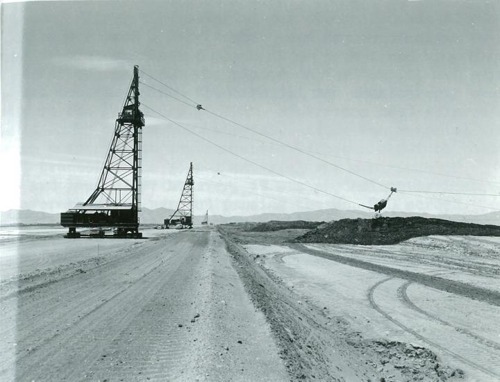
15 Willard Bay of Great Salt Lake Sta BACKGROUND Sta Willard Reservoir Wasatch Front Fault Reservoir Constructed by Bureau of Reclamation 1957 to Reclaimed land from Great Salt Lake Dam Length = 14.5 Miles Surface area 10,000 acres Reservoir operated by Weber Basin Water Conservancy District
 Length: 14.")
16 Arthur V. Watkins Dam (Willard Bay Reservoir) Height: 36 feet maximum (El ) Length: 14.5 miles 17,060,000 cubic yards of material Offstream storage facility: 215,000 acre-feet
17
18 Wasatch Front General Geology
. Lake Bonneville deposits hundreds to thousands of feet thick, soft lacustrine clays, silts and sands. A.V.")
19 Wasatch Front General Geology Dry bay of Great Salt Lake in historic times Former Glacial Lake Bonneville drained Late Pleistocene ( 14,500 yrs ago). Lake Bonneville deposits hundreds to thousands of feet thick, soft lacustrine clays, silts and sands. A.V. Watkins Dam built on Willard Bay.
20 A.V. Watkins Geologic Units Emb Embankment silty sand, silt, clay and roadbase/fill gravels Qsl Quaternary (Holocene) shoreline deposits consist of interbedded sand, silty sand, silt and clay. Youngest deposit which overlies the Qbs on east and southwest reaches of dam modification. Interbedded with alluvial fan deposits from Wasatcn Front C14 Age ~4K yrs Qbs Quaternary (Late Pleistocene) beach sands consist of silty sand (SM) and poorly graded sand (SP), overlie sandy silt (ML). Hardpan occurs in upper SP-SM layers of Qbs. Directly overlies Qbc in most of mod reach. C14 age = ~ K ybp Qbc Quaternary (Pleistocene) Bonneville Clay Ex Soft clay deposit of Glacial Lake Bonneville Zero blowcount material. Top of clay varies by several feet, so depth of wall varies to meet minimum penetration depth requirement. Pre-dam borings encountered pockets of swamp-gas, presumed to be methane. C14 age = 12.5 >15K ybp Hard-pan Shoreline or near-shore carbonate evaporite deposits which exist as layers in the Qsl related to recent historic levels of the GRL. Consists of sand cemented by calcium carbonate and iron. Generally a few tenths of a foot thick up to 3 feet - Upper hard-pan within 3 feet of ground surface - Lower hard-pan within 7-8 feet of ground surface

21 Hard-pan Fine sand and silt Silty sand and silt Bonneville Clay A.V. Watkins Dam General Cross-Section
22 Geologic/Engineering Challenges at the Dam Site (Given the state-of-practice now) - Low density non-plastic beach sand and silt for 6 miles of proposed foundation (Qsl and Qbs) - Beach sands are highly erodible and uniformly graded - Entire site founded on very soft, sensitive Bonneville Clays (in some areas underlying beach deposits and in other areas, the dike is founded directly on the Bonneville Clay - Bonneville Clay: 1. Unconsolidated lean to fat clay (CL,CH), organic (methane gas) and susceptible to significant settlements when loaded 2. Standard Penetration Test (SPT) blow counts = 0 3. CPT data and vane shear indicate sensitive clays (6-8) and low undrained strength ratios S u /s v = High groundwater table - Artesian water conditions on east side fed by alluvial fans of the Wasatch Front - Qsl and Qbs saturated and potentially liquefiable - Site within ¼ mile of Wasatch Fault - Site is susceptible to tilting downward to the east during a large seismic event leading to seiche wave overtopping
23 Geologic/Engineering Challenges at the Dam Site (Given the state-of-practice now) General Observations oat the time (early 1960s) the state-of-practice was much less evolved in particular: filter design and seismic design oengineers like a challenge othis dam site allows the capture of significant volumes of runoff that previously had to be passed through the upper reservoirs and into the Great Salt Lake onot all factors from previous slide considered in the design oin this case Ignorance was not BLISS!

24 Stages of Construction: 1. Sand & Gravel Dike, then fill 2. Zones 1, 2, & 3 up to elevation Zones 1, 3, and riprap facing to Maximum settlement approx. 18 ft.+ 5. Stage 4 Dam raised to El. 4235
25


26
27


28
29

30
31

32
33
34 Early role of geology in the embankment performance
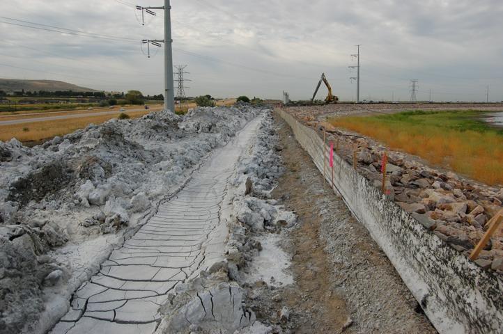
35 Early role of geology in the embankment performance Note open channel excavated to help drain Site for dam and agriculture known as South Drain
36 Early role of geology in the embankment performance Note open channel excavated to help drain Site for dam and agriculture known as South Drain
37 Early role of geology in the embankment performance Note open channel excavated to help drain Site for dam and agriculture known as South Drain
38 Early role of geology in the embankment performance Note open channel excavated to help drain Site for dam and agriculture known as South Drain First filling in 1964
39 Early role of geology in the embankment performance Note open channel excavated to help drain Site for dam and agriculture known as South Drain First filling in 1964 Quick conditions noted for thousands of feet at south section
40 Early role of geology in the embankment performance Note open channel excavated to help drain Site for dam and agriculture known as South Drain First filling in 1964 Quick conditions noted for thousands of feet at south section Decision made to install toe drain approx. 4 miles along southern length of dam (unfiltered open-jointed clay tile pipe)

41 Early role of geology in the embankment performance Note open channel excavated to help drain Site for dam and agriculture known as South Drain First filling in 1964 Quick conditions noted for thousands of feet at south section Decision made to install toe drain approx. 4 miles along southern length of dam (unfiltered open-jointed clay tile pipe) Dam filled successfully in 1965
42
43 Safety Of Dams Project Overview Three Phases
44 Safety Of Dams Project Overview Three Phases Emergency Response Dam nearly failed during Nov. 13, 2006 incident Completed November 2006
45 Safety Of Dams Project Overview Three Phases Emergency Response Dam nearly failed during Nov. 13, 2006 incident Completed November 2006
46 Safety Of Dams Project Overview Three Phases Emergency Response Dam nearly failed during Nov. 13, 2006 incident Completed November 2006 Phase I Forensic geologic and geotechnical investigations Interim repairs made to embankment/toe drain to allow restricted storage to El (NWS = 4226) Completed May 2007
47 Safety Of Dams Project Overview Three Phases Emergency Response Dam nearly failed during Nov. 13, 2006 incident Completed November 2006 Phase I Forensic geologic and geotechnical investigations Interim repairs made to embankment/toe drain to allow restricted storage to El (NWS = 4226) Completed May 2007
48 Safety Of Dams Project Overview Three Phases Emergency Response Dam nearly failed during Nov. 13, 2006 incident Completed November 2006 Phase I Forensic geologic and geotechnical investigations Interim repairs made to embankment/toe drain to allow restricted storage to El (NWS = 4226) Completed May 2007 Phase II Design geologic investigations performed Permanent repairs made via CB Cutoff Wall and embankment reconstruction Completed in November 2008 (1 yr. ahead of schedule)
49 Safety Of Dams Project Overview Three Phases Emergency Response Dam nearly failed during Nov. 13, 2006 incident Completed November 2006 Phase I Forensic geologic and geotechnical investigations Interim repairs made to embankment/toe drain to allow restricted storage to El (NWS = 4226) Completed May 2007 Phase II Design geologic investigations performed Permanent repairs made via CB Cutoff Wall and embankment reconstruction Completed in November 2008 (1 yr. ahead of schedule)
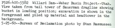
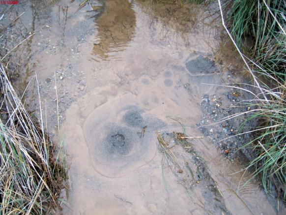
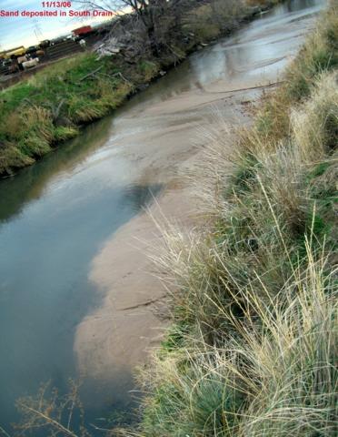
50 Emergency Response Feed lot operator noticed piping into South Drain on Saturday November 11, 2006 Monday November 13 - he notifies Water District Monday evening November 13 - Foundation piping at AV Watkins Dam (Station ) observed by USBR and Water District staff Sand boils at toe of dam, sand deposits in South Drain, sinkholes, tension cracks and slope failures on downstream slope, transverse crack in crest Emergency response begins November 13 including plans to breach dam into Great Salt Lake if necessary Dam finally stabilized on November 18
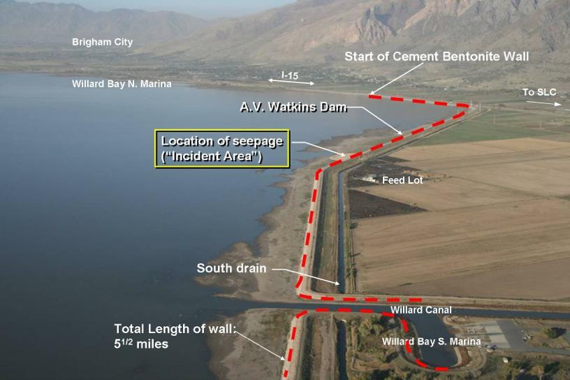
51 Brigham City Willard Bay N. Marina I-15 A.V. Watkins Dam To SLC Location of Near Failure Event Incident Area Feed Lot South Drain Willard Canal Willard Bay S. Marina
52

53 A.V. Watkins Dam November 2006 Failure Incident
54
55
56 Estimated 400 cubic yards of eroded material in South Drain

57 Estimated 400 cubic yards of eroded material in South Drain
58 Emergency Response A.V. Watkins Dam- Initial Observations
59 Emergency Response A.V. Watkins Dam- Initial Observations Seepage was gpm- coming from 1 large sand boil at the toe and several smaller sand boils a short distance from toe
60 Emergency Response A.V. Watkins Dam- Initial Observations Seepage was gpm- coming from 1 large sand boil at the toe and several smaller sand boils a short distance from toe Small slump on d/s face with crest crackingtransverse and parallel to axis
61 Emergency Response A.V. Watkins Dam- Initial Observations Seepage was gpm- coming from 1 large sand boil at the toe and several smaller sand boils a short distance from toe Small slump on d/s face with crest crackingtransverse and parallel to axis Numerous sinkholes 2-5 in dia. between toe and South Drain- random pattern
62 Emergency Response A.V. Watkins Dam- Initial Observations Seepage was gpm- coming from 1 large sand boil at the toe and several smaller sand boils a short distance from toe Small slump on d/s face with crest crackingtransverse and parallel to axis Numerous sinkholes 2-5 in dia. between toe and South Drain- random pattern Reduction in seepage flow most likely resulted from collapse of erosion path roof and settlement of dam
63 Emergency Response A.V. Watkins Dam- Initial Observations Seepage was gpm- coming from 1 large sand boil at the toe and several smaller sand boils a short distance from toe Small slump on d/s face with crest crackingtransverse and parallel to axis Numerous sinkholes 2-5 in dia. between toe and South Drain- random pattern Reduction in seepage flow most likely resulted from collapse of erosion path roof and settlement of dam No seepage was coming from dam
64 A.V. Watkins Dam- Emergency Response
65 A.V. Watkins Dam- Emergency Response Immediate goal was to stop foundation erosion
66 A.V. Watkins Dam- Emergency Response Immediate goal was to stop foundation erosion Construction equipment and sand/gravel were available nearby
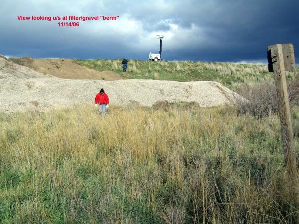
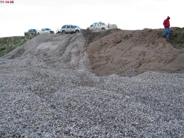
67 A.V. Watkins Dam- Emergency Response Immediate goal was to stop foundation erosion Construction equipment and sand/gravel were available nearby Decision was made within minutes to construct a filter and berm over the leak and surrounding area
68 A.V. Watkins Dam- Emergency Response Immediate goal was to stop foundation erosion Construction equipment and sand/gravel were available nearby Decision was made within minutes to construct a filter and berm over the leak and surrounding area Work was complicated by heavy rain and darkness
69 A.V. Watkins Dam- Emergency Response Immediate goal was to stop foundation erosion Construction equipment and sand/gravel were available nearby Decision was made within minutes to construct a filter and berm over the leak and surrounding area Work was complicated by heavy rain and darkness Declared EAP Response Level 1 but implemented most steps from Response Level 2
70 A.V. Watkins Dam- Emergency Response Immediate goal was to stop foundation erosion Construction equipment and sand/gravel were available nearby Decision was made within minutes to construct a filter and berm over the leak and surrounding area Work was complicated by heavy rain and darkness Declared EAP Response Level 1 but implemented most steps from Response Level 2 Stationed equipment on west dam (LOW hazard section) and instructed operator to breach the dam to allow harmless emptying into Great Salt Lake if conditions became critical at leak
71

72
73

74 Erosion downstream not halted until upstream sinkholes covered with gravel and pit-run material
75 A.V. Watkins Dam- Forensics
76 A.V. Watkins Dam- Forensics Investigations included geophysics, drilling and test pits at site of leak and expanded from there
77 A.V. Watkins Dam- Forensics Investigations included geophysics, drilling and test pits at site of leak and expanded from there Examined toe drain w/ Video Crawler & trench
78 A.V. Watkins Dam- Forensics Investigations included geophysics, drilling and test pits at site of leak and expanded from there Examined toe drain w/ Video Crawler & trench u/s toe examined for sinkholes or other evidence of seepage entry
79 A.V. Watkins Dam- Forensics Investigations included geophysics, drilling and test pits at site of leak and expanded from there Examined toe drain w/ Video Crawler & trench u/s toe examined for sinkholes or other evidence of seepage entry Test pitting complicated by high water table, flowing sand, etc. Surface observations complicated by snow/ice cover
80 A.V. Watkins Dam- Forensics Investigations included geophysics, drilling and test pits at site of leak and expanded from there Examined toe drain w/ Video Crawler & trench u/s toe examined for sinkholes or other evidence of seepage entry Test pitting complicated by high water table, flowing sand, etc. Surface observations complicated by snow/ice cover Detailed temperature surveys made in South Drain and finger drains looking for seepage entrance points into South Drain

81 Trenches Excavated through Sinkholes and along downstream toe of dam

82 Open collapsed piping conduit in sand above lower hard-pan. Note iron-staining possibly indicates this feature formed over some period of time. photo by R. Pearson

83 Clean, well graded sand deposited in piping conduit after flow choked-off Exposed in sidewall of trench below upper hard-pan. R. Pearson

84 Emergent groundwater under pressure when hard-pan layer broken. photo R. Pearson

85 photo R. Pearson

86 Hard-pan layers form overhang fine piped sand deposited in South Drain. photo R. Pearson
 high levels of Great Salt Lake.")
87 Calcium Carbonate cemented sand forms layers of hard-pan Layers conform to historic (~past 1000 yr.) high levels of Great Salt Lake. Photo TSC Petro Lab
88 Failure Mode Conclusion and Geologic Factors Influencing the Failure Mode
89 Failure Mode Conclusion and Geologic Factors Influencing the Failure Mode Reservoir at or above threshold level
90 Failure Mode Conclusion and Geologic Factors Influencing the Failure Mode Reservoir at or above threshold level Yes Reservoir kept as full as possible year round
91 Failure Mode Conclusion and Geologic Factors Influencing the Failure Mode Reservoir at or above threshold level Yes Reservoir kept as full as possible year round Initiation Erosion starts
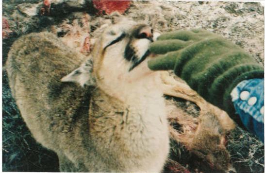
92 Failure Mode Conclusion and Geologic Factors Influencing the Failure Mode Reservoir at or above threshold level Yes Reservoir kept as full as possible year round Initiation Erosion starts Yes May have been due to animal burrowing and increased seepage gradient and Qls highly erodible at low seepage gradients (0.06)
93 Failure Mode Conclusion and Geologic Factors Influencing the Failure Mode Reservoir at or above threshold level Yes Reservoir kept as full as possible year round Initiation Erosion starts Yes May have been due to animal burrowing and increased seepage gradient and Qls highly erodible at low seepage gradients (0.06) Continuation - Unfiltered or inadequately filtered exit exists
94 Failure Mode Conclusion and Geologic Factors Influencing the Failure Mode Reservoir at or above threshold level Yes Reservoir kept as full as possible year round Initiation Erosion starts Yes May have been due to animal burrowing and increased seepage gradient and Qls highly erodible at low seepage gradients (0.06) Continuation - Unfiltered or inadequately filtered exit exists Yes South drain and open-jointed bell and spigot sewer pipe toe drain
95 Failure Mode Conclusion and Geologic Factors Influencing the Failure Mode Reservoir at or above threshold level Yes Reservoir kept as full as possible year round Initiation Erosion starts Yes May have been due to animal burrowing and increased seepage gradient and Qls highly erodible at low seepage gradients (0.06) Continuation - Unfiltered or inadequately filtered exit exists Yes South drain and open-jointed bell and spigot sewer pipe toe drain Progression Continuous stable roof and/or sidewalls
96 Failure Mode Conclusion and Geologic Factors Influencing the Failure Mode Reservoir at or above threshold level Yes Reservoir kept as full as possible year round Initiation Erosion starts Yes May have been due to animal burrowing and increased seepage gradient and Qls highly erodible at low seepage gradients (0.06) Continuation - Unfiltered or inadequately filtered exit exists Yes South drain and open-jointed bell and spigot sewer pipe toe drain Progression Continuous stable roof and/or sidewalls Yes Relatively continuous hard-pan layer at incident location
97 Failure Mode Conclusion and Geologic Factors Influencing the Failure Mode Reservoir at or above threshold level Yes Reservoir kept as full as possible year round Initiation Erosion starts Yes May have been due to animal burrowing and increased seepage gradient and Qls highly erodible at low seepage gradients (0.06) Continuation - Unfiltered or inadequately filtered exit exists Yes South drain and open-jointed bell and spigot sewer pipe toe drain Progression Continuous stable roof and/or sidewalls Yes Relatively continuous hard-pan layer at incident location Progression Constriction or upstream zone fails to limit flows
98 Failure Mode Conclusion and Geologic Factors Influencing the Failure Mode Reservoir at or above threshold level Yes Reservoir kept as full as possible year round Initiation Erosion starts Yes May have been due to animal burrowing and increased seepage gradient and Qls highly erodible at low seepage gradients (0.06) Continuation - Unfiltered or inadequately filtered exit exists Yes South drain and open-jointed bell and spigot sewer pipe toe drain Progression Continuous stable roof and/or sidewalls Yes Relatively continuous hard-pan layer at incident location Progression Constriction or upstream zone fails to limit flows Yes No u/s zone to limit flows
99 Failure Mode Conclusion and Geologic Factors Influencing the Failure Mode Reservoir at or above threshold level Yes Reservoir kept as full as possible year round Initiation Erosion starts Yes May have been due to animal burrowing and increased seepage gradient and Qls highly erodible at low seepage gradients (0.06) Continuation - Unfiltered or inadequately filtered exit exists Yes South drain and open-jointed bell and spigot sewer pipe toe drain Progression Continuous stable roof and/or sidewalls Yes Relatively continuous hard-pan layer at incident location Progression Constriction or upstream zone fails to limit flows Yes No u/s zone to limit flows Progression No self-healing by upstream zone
100 Failure Mode Conclusion and Geologic Factors Influencing the Failure Mode Reservoir at or above threshold level Yes Reservoir kept as full as possible year round Initiation Erosion starts Yes May have been due to animal burrowing and increased seepage gradient and Qls highly erodible at low seepage gradients (0.06) Continuation - Unfiltered or inadequately filtered exit exists Yes South drain and open-jointed bell and spigot sewer pipe toe drain Progression Continuous stable roof and/or sidewalls Yes Relatively continuous hard-pan layer at incident location Progression Constriction or upstream zone fails to limit flows Yes No u/s zone to limit flows Progression No self-healing by upstream zone Yes No u/s zone to cause self-healing
101 Failure Mode Conclusion and Geologic Factors Influencing the Failure Mode Reservoir at or above threshold level Yes Reservoir kept as full as possible year round Initiation Erosion starts Yes May have been due to animal burrowing and increased seepage gradient and Qls highly erodible at low seepage gradients (0.06) Continuation - Unfiltered or inadequately filtered exit exists Yes South drain and open-jointed bell and spigot sewer pipe toe drain Progression Continuous stable roof and/or sidewalls Yes Relatively continuous hard-pan layer at incident location Progression Constriction or upstream zone fails to limit flows Yes No u/s zone to limit flows Progression No self-healing by upstream zone Yes No u/s zone to cause self-healing Intervention fails
102 Failure Mode Conclusion and Geologic Factors Influencing the Failure Mode Reservoir at or above threshold level Yes Reservoir kept as full as possible year round Initiation Erosion starts Yes May have been due to animal burrowing and increased seepage gradient and Qls highly erodible at low seepage gradients (0.06) Continuation - Unfiltered or inadequately filtered exit exists Yes South drain and open-jointed bell and spigot sewer pipe toe drain Progression Continuous stable roof and/or sidewalls Yes Relatively continuous hard-pan layer at incident location Progression Constriction or upstream zone fails to limit flows Yes No u/s zone to limit flows Progression No self-healing by upstream zone Yes No u/s zone to cause self-healing Intervention fails NO Intervention was successful


103 A.V. Watkins Dam - Failure Mode


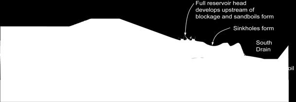
104 A.V. Watkins Dam - Failure Mode
105 Geologic Factors Influencing the Failure Mode Lacustrine deposits of highly erodible, low density, fine sand and silt in the foundation Fine sand and silt were very uniform.low probability of self filtering within coarser zone Unfiltered exit at South Drain (man-made) Presence of continuous hard-pan layers capable of forming a roof for a backwards erosion piping conduit Low density foundation soils capable of large settlements
106 A.V. Watkins Dam Interim Modifications for Restricted Storage District needed to store as much water as possible in order to support community needs (3 feet of water is worth approximately $50 million) Interim construction measures include: Enlarging the upstream berm to remove reservoir from the incident area Installing a modern toe drain and monitoring system within the incident area Allow for restricted filling to 4214 under 24-hour monitoring (4226 is top of normal pool)

107

108
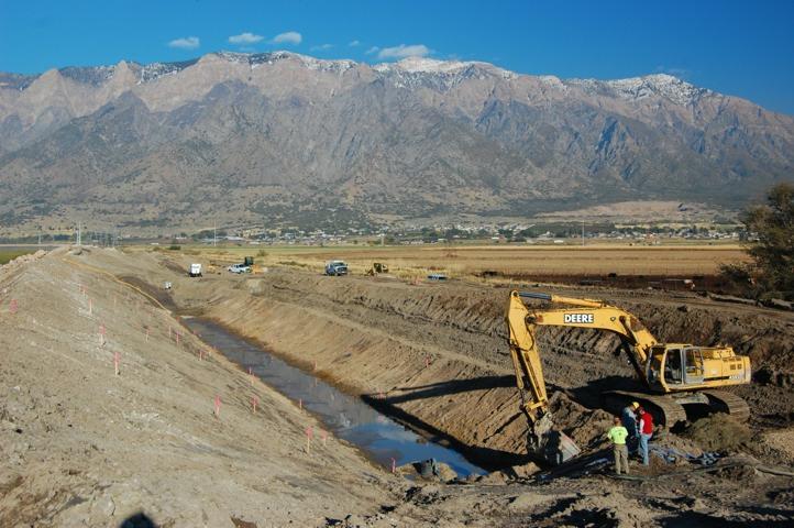
109 A.V. Watkins Dam Dam Repair for Full Operations Permanent Repair allows for facility to be put back into full service by reducing risk of static piping failure below Reclamation SOD guidelines Reconstruct embankment in incident area Stop / cut off / intercept seepage and piping paths Corrective Action-Design Investigations SPT, Test Pits and CPT over 6 mile reach
110 A.V. Watkins Dam Geologic Factors Impacting Design Considerations
111 A.V. Watkins Dam Geologic Factors Impacting Design Considerations Erodible silts and fine sands
112 A.V. Watkins Dam Geologic Factors Impacting Design Considerations Erodible silts and fine sands - Reduce seepage gradients at d/s toe and South Drain
113 A.V. Watkins Dam Geologic Factors Impacting Design Considerations Erodible silts and fine sands - Reduce seepage gradients at d/s toe and South Drain - Provide filtered exits for all locations (toe, South Drain, and area in between)
114 A.V. Watkins Dam Geologic Factors Impacting Design Considerations Erodible silts and fine sands - Reduce seepage gradients at d/s toe and South Drain - Provide filtered exits for all locations (toe, South Drain, and area in between) - Preferred alternative should address the possibility of existing voids from undiscovered piping erosion
115 A.V. Watkins Dam Geologic Factors Impacting Design Considerations Erodible silts and fine sands - Reduce seepage gradients at d/s toe and South Drain - Provide filtered exits for all locations (toe, South Drain, and area in between) - Preferred alternative should address the possibility of existing voids from undiscovered piping erosion - Dewatering very difficult due to low permeability
116 A.V. Watkins Dam Geologic Factors Impacting Design Considerations Erodible silts and fine sands - Reduce seepage gradients at d/s toe and South Drain - Provide filtered exits for all locations (toe, South Drain, and area in between) - Preferred alternative should address the possibility of existing voids from undiscovered piping erosion - Dewatering very difficult due to low permeability
117 A.V. Watkins Dam Geologic Factors Impacting Design Considerations Erodible silts and fine sands - Reduce seepage gradients at d/s toe and South Drain - Provide filtered exits for all locations (toe, South Drain, and area in between) - Preferred alternative should address the possibility of existing voids from undiscovered piping erosion - Dewatering very difficult due to low permeability Hard Pan Layers
118 A.V. Watkins Dam Geologic Factors Impacting Design Considerations Erodible silts and fine sands - Reduce seepage gradients at d/s toe and South Drain - Provide filtered exits for all locations (toe, South Drain, and area in between) - Preferred alternative should address the possibility of existing voids from undiscovered piping erosion - Dewatering very difficult due to low permeability Hard Pan Layers - Break up hard pan if possible
119 A.V. Watkins Dam Geologic Factors Impacting Design Considerations Erodible silts and fine sands - Reduce seepage gradients at d/s toe and South Drain - Provide filtered exits for all locations (toe, South Drain, and area in between) - Preferred alternative should address the possibility of existing voids from undiscovered piping erosion - Dewatering very difficult due to low permeability Hard Pan Layers - Break up hard pan if possible - Provide Hydraulic pressure relief below lower hard pan layer
120 A.V. Watkins Dam Geologic Factors Impacting Design Considerations Erodible silts and fine sands - Reduce seepage gradients at d/s toe and South Drain - Provide filtered exits for all locations (toe, South Drain, and area in between) - Preferred alternative should address the possibility of existing voids from undiscovered piping erosion - Dewatering very difficult due to low permeability Hard Pan Layers - Break up hard pan if possible - Provide Hydraulic pressure relief below lower hard pan layer
121 A.V. Watkins Dam Geologic Factors Impacting Design Considerations Erodible silts and fine sands - Reduce seepage gradients at d/s toe and South Drain - Provide filtered exits for all locations (toe, South Drain, and area in between) - Preferred alternative should address the possibility of existing voids from undiscovered piping erosion - Dewatering very difficult due to low permeability Hard Pan Layers - Break up hard pan if possible - Provide Hydraulic pressure relief below lower hard pan layer Concerns for soft Bonneville Clay in the foundation
122 A.V. Watkins Dam Geologic Factors Impacting Design Considerations Erodible silts and fine sands - Reduce seepage gradients at d/s toe and South Drain - Provide filtered exits for all locations (toe, South Drain, and area in between) - Preferred alternative should address the possibility of existing voids from undiscovered piping erosion - Dewatering very difficult due to low permeability Hard Pan Layers - Break up hard pan if possible - Provide Hydraulic pressure relief below lower hard pan layer Concerns for soft Bonneville Clay in the foundation - Minimize additional fill that could lead to settlement (especially
123 A.V. Watkins Dam - Alternatives
124 A.V. Watkins Dam - Alternatives Design Options:
125 A.V. Watkins Dam - Alternatives Design Options: 1. U/S Cutoff Wall
126 A.V. Watkins Dam - Alternatives Design Options: 1. U/S Cutoff Wall 2. Cutoff Wall through Crest
127 A.V. Watkins Dam - Alternatives Design Options: 1. U/S Cutoff Wall 2. Cutoff Wall through Crest 3. Filter / drainage blanket at D/S toe
128 A.V. Watkins Dam - Alternatives Design Options: 1. U/S Cutoff Wall 2. Cutoff Wall through Crest 3. Filter / drainage blanket at D/S toe 4. Filter intercept trench/keyway between toe and South Drain
129 A.V. Watkins Dam - Alternatives Design Options: 1. U/S Cutoff Wall 2. Cutoff Wall through Crest 3. Filter / drainage blanket at D/S toe 4. Filter intercept trench/keyway between toe and South Drain 5. Combinations of above alternatives
130 A.V. Watkins Dam - Alternatives Design Options: 1. U/S Cutoff Wall 2. Cutoff Wall through Crest 3. Filter / drainage blanket at D/S toe 4. Filter intercept trench/keyway between toe and South Drain 5. Combinations of above alternatives
131 A.V. Watkins Dam - Alternatives Design Options: 1. U/S Cutoff Wall 2. Cutoff Wall through Crest 3. Filter / drainage blanket at D/S toe 4. Filter intercept trench/keyway between toe and South Drain 5. Combinations of above alternatives
132 A.V. Watkins Dam - Alternatives Design Options: 1. U/S Cutoff Wall 2. Cutoff Wall through Crest 3. Filter / drainage blanket at D/S toe 4. Filter intercept trench/keyway between toe and South Drain 5. Combinations of above alternatives
133 A.V. Watkins Dam - Alternatives Design Options: 1. U/S Cutoff Wall 2. Cutoff Wall through Crest 3. Filter / drainage blanket at D/S toe 4. Filter intercept trench/keyway between toe and South Drain 5. Combinations of above alternatives

134
135 4K yrs 15K yr
136 Detailed geologic investigations to define limits of cutoff wall (drill holes, CPT, SPT) 4K yrs 15K yr
137 Detailed geologic investigations to define limits of cutoff wall (drill holes, CPT, SPT) 4K yrs 15K yr
138 Detailed geologic investigations to define limits of cutoff wall (drill holes, CPT, SPT) 4K yrs 15K yr East end of CB cutoff wall Sta
 4K yrs 15K yr East end of CB cutoff wall Sta.")
139 Detailed geologic investigations to define limits of cutoff wall (drill holes, CPT, SPT) 4K yrs 15K yr East end of CB cutoff wall Sta
140 Location Map
141
142 Cement-Bentonite Cutoff Wall Contract Awarded May 28, 2008 Geo-Solutions, Inc. (Slurry Production) New Kensington, PA Nordic Industries Marysville, CA $17.4 Million

143 July 2008
144 Baker tank contained 12,000 gallons of water, Super-sack of bentonite = 3,000 lbs. 1 tank water for every 2 bags bentonite.


145 Bentonite Slurry Mix (by weight of water): 6% Sodium Montmorillonite Bentonite API 13A section 9 Baker tank contained 12,000 gallons of water, Super-sack of bentonite = 3,000 lbs. 1 tank water for every 2 bags bentonite.
146
: 6% Bentonite")
")
147 Cement-Bentonite Slurry Mix (by weight of water): 6% Bentonite 18% Cement (Type V) Admixtures (as per manuf. Recommendations)
148 Lignosulfonate added continuously to cement-bentonite as a plasticizer and set retarder A highly anionic polymer used to deflocculate clay-based muds. Lignosulfonate is a byproduct of the sulfite method for manufacturing paper from wood pulp. Sometimes it is called sulfonated lignin. Lignosulfonate is a complex mixture of small- to moderate-sized polymeric compounds with sulfonate groups attached to the molecule.


149 Lignosulfonate added continuously to cement-bentonite as a plasticizer and set retarder A highly anionic polymer used to deflocculate clay-based muds. Lignosulfonate is a byproduct of the sulfite method for manufacturing paper from wood pulp. Sometimes it is called sulfonated lignin. Lignosulfonate is a complex mixture of small- to moderate-sized polymeric compounds with sulfonate groups attached to the molecule.
150


151 At full daily production (2 shifts): 350 tons cement 115 tons bentonite 340,000 gallons water CB slurry supply rate = 1 to 2.2 cubic yards / min.


152 Komatsu PC1250 Excavator with custom built boom, automatic lubrication system, and oversized hydraulic cylinders Curbside weight = 265,000 lbs

153
154


155

156
157


158 Cut 5 feet (minimum) into CB from previous day in order to prevent windows in wall

159
160
161 Qbs/Qbc interface

162 Qbs/Qbc interface
163

164
165 Cost per day up to $200,000 Cost per week over $1 Million


166 Typical production (double shifts): 320 to 480 linear feet per day (16,000 to 22,000 ft 2 per day) Cost per day up to $200,000 Cost per week over $1 Million

167

168
169 November 21, 2008

")
170 Wall completed! 6 miles long 1.57 Million ft 2 Permeability (28 day) = 5.8 x 10⁻⁶ cm/sec Strength (28 day) = 12 psi November 21, 2008

171 Section at Incident Area
172 Bio-Polymer Slurry 550 gallons Water 25 lbs Natural Guar 2 Quarts Soda Ash 1/3 Quart Synthetic Guar Recirculate in tank until MFV and ph stabilizes

173

174
175

176

177

178

179
180

181 Incident area reconstruction

182 Reservoir May 8, 2009 Elevation: (1.5 feet from full)
183 A.V. Watkins Dam - Summary Geologic factors made all the difference in the development of the failure mode: Erodible foundation soils (erodible under very small seepage gradients) Unfiltered seepage exit Roof-forming unit (hardpan) Geologic Factors are Critical in determination of the Limits of the SOD Modification C-B Cutoff Wall Understanding geology key to defining limits of Qbs deposit to define length of modification Understanding geology key to defining depth to Qbc deposit to determine depth for cutoff Understanding geology key to developing specifications to define hard-pan layers and difficulty of excavation, dewatering.

184 Questions?
Geosynthetics Applications and Performance Reviews Select Case Histories
 Geosynthetics Applications and Performance Reviews Select Case Histories Debora J. Miller, Ph.D., P.E.; Dean B. Durkee,, Ph.D., P.E.; Michael A. Morrison, P.E., David B. Wilson, P.E., and Kevin Smith,
STRUCTURAL STABILITY ASSESSMENT
 STRUCTURAL STABILITY ASSESSMENT CFR 257.73(d) Bottom Ash Pond Complex Cardinal Plant Brilliant, Ohio October, 2016 Prepared for: Cardinal Operating Company Cardinal Plant Brilliant, Ohio Prepared by: Geotechnical
FRED BURR DAM FEASIBILITY STUDY
 FRED BURR DAM FEASIBILITY STUDY Fred Burr Dam Feasibility Study Purpose: Develop pre-feasibility risk reduction alternatives and recommendations for short-term operations and long-term rehabilitation.
Teton Dam Failure A Review of the Technical Factors Contributing to the Failure
 Teton Dam Failure A Review of the Technical Factors Contributing to the Failure Outline of Presentation Location, Background and Project Statistics Technical Causes of Failure to be Discussed Geology
Big Rivers Electric Corporation Disposal of Coal Combustion Residuals (CCR) from Electric Utilities Final Rule CCR Impoundment Liner Assessment Report
 from Electric Utilities Final Rule CCR Impoundment Liner Assessment Report") Big Rivers Electric Corporation Disposal of Coal Combustion Residuals (CCR) from Electric Utilities Final Rule CCR Impoundment Liner Assessment Report CCR Surface Impoundment Information Name: Operator:
Big Rivers Electric Corporation Disposal of Coal Combustion Residuals (CCR) from Electric Utilities Final Rule CCR Impoundment Liner Assessment Report CCR Surface Impoundment Information Name: Operator:
Materials. Use materials meeting the following.
 208.01 Section 208. SOIL EROSION AND SEDIMENTATION CONTROL 208.01 Description. Install and maintain erosion and sedimentation controls to minimize soil erosion and to control sedimentation from affecting
Amistad Dam Investigation and Oversight: Karst- Founded Dam on the USA-Mexico Border
 Amistad Dam Investigation and Oversight: Karst- Founded Dam on the USA-Mexico Border Brook Brosi, CPG, PG USACE Lisa Nowicki Perks, PG USACE Kimberly Heenan, PE AECOM US Army Corps of Engineers BUILDING
CCR Rule Annual Inspection Report (cont.) 2
 2") The inspection findings consisted of maintenance items and items that were not observed to be signs or potential signs of significant structural weakness. No deficiencies or disrupting conditions that
The inspection findings consisted of maintenance items and items that were not observed to be signs or potential signs of significant structural weakness. No deficiencies or disrupting conditions that
Converse Consultants Geotechnical Engineering, Environmental & Groundwater Science, Inspection & Testing Services
 Converse Consultants Geotechnical Engineering, Environmental & Groundwater Science, Inspection & Testing Services Ms. Rebecca Mitchell Mt. San Antonio College Facilities Planning & Management 1100 North
This report was prepared by Klohn Crippen Consultants Ltd. for Alberta Transportation Central Region under Contract No. CE053/2000.
 Alberta Transportation Central Region #401, 4902 51 Street Red Deer, Alberta T4N 6K8 June 7, 2002 Mr. Melvin Mayfield, P.Eng. Project Engineer Dear Mr. Mayfield: Central Region Landslide Assessment Site
design, construction, operation, and maintenance of the BAP is consistent with recognized and generally accepted good engineering standards.
 design, construction, operation, and maintenance of the BAP is consistent with recognized and generally accepted good engineering standards. In addition to the field inspection, Associated Engineers, Inc.
Instructor : Dr. Jehad Hamad. Chapter (7)
") Instructor : Dr. Jehad Hamad Chapter (7) 2017-2016 Soil Properties Physical Properties Mechanical Properties Gradation and Structure Compressibility Soil-Water Relationships Shear Strength Bearing Capacity
Instructor : Dr. Jehad Hamad Chapter (7) 2017-2016 Soil Properties Physical Properties Mechanical Properties Gradation and Structure Compressibility Soil-Water Relationships Shear Strength Bearing Capacity
IV. ENVIRONMENTAL IMPACT ANALYSIS G. GEOLOGY AND SOILS
 IV. ENVIRONMENTAL IMPACT ANALYSIS G. GEOLOGY AND SOILS The following section is a summary of the geotechnical report conducted for the proposed project. The Report of Geotechnical Investigation Proposed
PERENNIAL PROBLEM OF EARTHEN BUND OF WELLINGDON RESERVOIR. ANALYSIS OF CAUSES AND REMEDIAL MEASURES A CASE STUDY.
 PERENNIAL PROBLEM OF EARTHEN BUND OF WELLINGDON RESERVOIR. ANALYSIS OF CAUSES AND REMEDIAL MEASURES A CASE STUDY. By Er. S. Muthu Parvatha Vardhini, Asst. Executive Engineer, (Designs) Water Resources
Soils, Hydrogeology, and Aquifer Properties. Philip B. Bedient 2006 Rice University
 Soils, Hydrogeology, and Aquifer Properties Philip B. Bedient 2006 Rice University Charbeneau, 2000. Basin Hydrologic Cycle Global Water Supply Distribution 3% of earth s water is fresh - 97% oceans 1%
Gotechnical Investigations and Sampling
 Gotechnical Investigations and Sampling Amit Prashant Indian Institute of Technology Gandhinagar Short Course on Geotechnical Investigations for Structural Engineering 12 14 October, 2017 1 Purpose of
Slope Stability Evaluation Ground Anchor Construction Area White Point Landslide San Pedro District Los Angeles, California.
 Slope Stability Evaluation Ground Anchor Construction Area White Point Landslide San Pedro District Los Angeles, California Submitted To: Mr. Gene Edwards City of Los Angeles Department of Public Works
ENGINEER S CERTIFICATION OF FAULT AREA DEMONSTRATION (40 CFR )
") PLATTE RIVER POWER AUTHORITY RAWHIDE ENERGY STATION BOTTOM ASH TRANSFER (BAT) IMPOUNDMENTS LARIMER COUNTY, CO ENGINEER S CERTIFICATION OF FAULT AREA DEMONSTRATION (40 CFR 257.62) FOR COAL COMBUSTION RESIDUALS
PLATTE RIVER POWER AUTHORITY RAWHIDE ENERGY STATION BOTTOM ASH TRANSFER (BAT) IMPOUNDMENTS LARIMER COUNTY, CO ENGINEER S CERTIFICATION OF FAULT AREA DEMONSTRATION (40 CFR 257.62) FOR COAL COMBUSTION RESIDUALS
HISTORY OF CONSTRUCTION FOR EXISTING CCR SURFACE IMPOUNDMENT PLANT GASTON ASH POND 40 CFR (c)(1)(i) (xii)
(1)(i) (xii)") HISTORY OF CONSTRUCTION FOR EXISTING CCR SURFACE IMPOUNDMENT PLANT GASTON ASH POND 40 CFR 257.73(c)(1)(i) (xii) (i) Site Name and Ownership Information: Site Name: E.C. Gaston Steam Plant Site Location:
HISTORY OF CONSTRUCTION FOR EXISTING CCR SURFACE IMPOUNDMENT PLANT GASTON ASH POND 40 CFR 257.73(c)(1)(i) (xii) (i) Site Name and Ownership Information: Site Name: E.C. Gaston Steam Plant Site Location:
CEMEX Eliot Quarry. Lake A Evaluation Report. Alameda County, California
 May 7, 2015 May 7, 2015 Project No. GT13-16 Prepared for: CEMEX 5180 Golden Foothills, Parkway El Dorado Hills, California 95762 7400 Shoreline Drive, Ste. 6 Stockton, California 95219 Tel: 209-472-1822
Landslides and Ground Water Permeability with Respect to the. Contact Point of Glacial Lake Vermont and the Champlain Sea
 Landslides and Ground Water Permeability with Respect to the Contact Point of Glacial Lake Vermont and the Champlain Sea Sediments at Town Line Brook, Winooski, VT Michala Peabody Lara Vowles Abstract:
patersongroup Consulting Engineers April 20, 2010 File: PG1887-LET.01R Novatech Engineering Consultants Suite 200, 240 Michael Cowpland Drive
 patersongroup April 20, 2010 File: PG1887-LET.01R Novatech Engineering Consultants Suite 200, 240 Michael Cowpland Drive Ottawa, Ontario K2M 1P6 Attention: Mr. Adam Thompson Consulting Engineers 28 Concourse
When Creek Meets Valley Wall: Prioritizing Erosion Mitigation alongside the Oshawa Landfill
 1 When Creek Meets Valley Wall: Prioritizing Erosion Mitigation alongside the Oshawa Landfill Robin McKillop 1, Dan McParland 1 & Cassie Scobie 2 TRIECA conference March 22-23, 2017 1 Palmer Environmental
November 20, 2003 Project
 November 20, 2003 Project 032810 1021 Main Street Winchester, MA 01890-1970 781.721.4000 781.721.4073 fax Mr. Bobby Van Cleave Geotechnical Engineer Little Rock District Federal Building, 7th Floor 700
THE NEED FOR AN ADDITIONAL SPILLWAY AT THE SANFORD DAM BOILING SPRING LAKES, NC. Presentation for The Brunswick County Commissioners April 20, 2015
 THE NEED FOR AN ADDITIONAL SPILLWAY AT THE SANFORD DAM BOILING SPRING LAKES, NC Presentation for The Brunswick County Commissioners April 20, 2015 The Sanford Dam Earth Dam constructed in 1961 Drainage
IN SITU SPECIFIC GRAVITY VS GRAIN SIZE: A BETTER METHOD TO ESTIMATE NEW WORK DREDGING PRODUCTION
 IN SITU SPECIFIC GRAVITY VS GRAIN SIZE: A BETTER METHOD TO ESTIMATE NEW WORK DREDGING PRODUCTION Nancy Case O Bourke, PE 1, Gregory L. Hartman, PE 2 and Paul Fuglevand, PE 3 ABSTRACT In-situ specific gravity
Countermeasure Calculations and Design
 Countermeasure Calculations and Design Summarized from Bridge Scour and Stream Instability Countermeasures, Experience, Selection, and Design Guidance, Second Edition, Publication No. FHWA NHI 01-003,
Chapter 12 Subsurface Exploration
 Page 12 1 Chapter 12 Subsurface Exploration 1. The process of identifying the layers of deposits that underlie a proposed structure and their physical characteristics is generally referred to as (a) subsurface
Horizontal Directional Drilling: An Approach to Design and Construction. Presenter: John Briand, PE Co-Author: Danielle Neamtu, PE
 Horizontal Directional Drilling: An Approach to Design and Construction Presenter: John Briand, PE Co-Author: Danielle Neamtu, PE Presentation Outline General HDD overview Conceptual-level evaluation Detailed
IMPORTANCE OF GEOLOGIC CHARACTERIZATION FOR LEVEE FOUNDATION AND BORROW MATERIALS AS STUDIED AT THE INDIAN GRAVES LEVEE DISTRICT, ADAMS COUNTY, IL
 IMPORTANCE OF GEOLOGIC CHARACTERIZATION FOR LEVEE FOUNDATION AND BORROW MATERIALS AS STUDIED AT THE INDIAN GRAVES LEVEE DISTRICT, ADAMS COUNTY, IL Conor Watkins Missouri University of Science and Technology
Calibration of Seepage and Stability Models for analysis of Dams and Levees. Francke C Walberg Consulting Geotechnical Engineer, AECOM
 Calibration of Seepage and Stability Models for analysis of Dams and Levees Francke C Walberg Consulting Geotechnical Engineer, AECOM Focus Use of models for; Evaluation of existing dams and levees Rehabilitation
Pierce County Department of Planning and Land Services Development Engineering Section
 Page 1 of 7 Pierce County Department of Planning and Land Services Development Engineering Section PROJECT NAME: DATE: APPLICATION NO.: PCDE NO.: LANDSLIDE HAZARD AREA (LHA) GEOLOGICAL ASSESSMENT REPORT
Background. Valley fills Sites in the Area. Construction over Mine Spoil Fills
 Construction over Mine Spoil Fills Wayne A. Karem, PhD, PE, PG, D.GE 2014 KSPE Annual Conference Background Strip mining; mountaintop and contour mining Creates huge quantities of mine spoil The mine spoil
PROBLEMS AND SOLUTIONS THAT MAY EMERGE IN THE FOUNDATION AND BODY OF A HOMOGENEOUS FILL DAM ON A WEAK CLAYEY-SILTY-SANDY FORMATION ÇIKRIKÇI DAM
 PROBLEMS AND SOLUTIONS THAT MAY EMERGE IN THE FOUNDATION AND BODY OF A HOMOGENEOUS FILL DAM ON A WEAK CLAYEY-SILTY-SANDY FORMATION ÇIKRIKÇI DAM Esen Yalım KARADUMAN BAR-SU Eng. & Conc. Inc. Ankara Turkey
Standards for Soil Erosion and Sediment Control in New Jersey May 2012
 STANDARD FOR SEDIMENT BASIN Definition A barrier, dam, excavated pit, or dugout constructed across a waterway or at other suitable locations to intercept and retain sediment. Basins created by construction
CENTRAL REGION GEOHAZARDS RISK ASSESSMENT SITE INSPECTION FORM
 SITE NUMBER AND NAME C55 H861:02 Slide LEGAL DESCRIPTION NW 14-40-14-W4 CENTRAL REGION GEOHAZARDS RISK ASSESSMENT SITE INSPECTION FORM HIGHWAY & KM NAD 83 COORDINATES N 5811217 E 437291 PREVIOUS INSPECTION
Sediment Trap. A temporary runoff containment area, which promotes sedimentation prior to discharge of the runoff through a stabilized spillway.
 Sediment Trap SC-15 Source: Caltrans Construction Site Best Management Practices Manual, 2003. Description A temporary runoff containment area, which promotes sedimentation prior to discharge of the runoff
b) EFFECTIVE STRESS (c) SEEPAGE
 EFFECTIVE STRESS (c) SEEPAGE") b) EFFECTIVE STRESS B1. A fine sand layer of 5 m thickness lies on a 5 m clay deposit. The water table is at the ground surface. Below the clay is a rock formation. Piezometers installed in the rock show
b) EFFECTIVE STRESS B1. A fine sand layer of 5 m thickness lies on a 5 m clay deposit. The water table is at the ground surface. Below the clay is a rock formation. Piezometers installed in the rock show
Boreholes. Implementation. Boring. Boreholes may be excavated by one of these methods: 1. Auger Boring 2. Wash Boring 3.
 Implementation Boreholes 1. Auger Boring 2. Wash Boring 3. Rotary Drilling Boring Boreholes may be excavated by one of these methods: 4. Percussion Drilling The right choice of method depends on: Ground
M E M O R A N D U M. Mr. Jonathan K. Thrasher, P.E., Mr. Ian Kinnear, P.E. (FL) PSI
 PSI") M E M O R A N D U M TO: FROM: Mr. Mark Schilling Gulf Interstate Engineering Mr. Jonathan K. Thrasher, P.E., Mr. Ian Kinnear, P.E. (FL) PSI DATE: November 11, 2014 RE: Summary of Findings Geotechnical
M E M O R A N D U M TO: FROM: Mr. Mark Schilling Gulf Interstate Engineering Mr. Jonathan K. Thrasher, P.E., Mr. Ian Kinnear, P.E. (FL) PSI DATE: November 11, 2014 RE: Summary of Findings Geotechnical
 Photo 1 - Southerly view across 2700 parking lot toward existing building. Multi-residential building borders western side of property in upper right of view. Photo 2 - Southerly view across 2750 parking
3.12 Geology and Topography Affected Environment
 3 Affected Environment and Environmental Consequences 3.12 Geology and Topography 3.12.1 Affected Environment 3.12.1.1 Earthquakes Sterling Highway MP 45 60 Project Draft SEIS The Kenai Peninsula is predisposed
B-1 SURFACE ELEVATION
 5A 5B LOGGED BY El. S. Bhangoo DRILLING CONTRACTOR Pitcher Drilling DRILLING METHOD Rotary Wash BEGIN DATE 12-14-12 SAMPLER TYPE(S) AND SIZE(S) (ID) SPT, MC BOREHOLE BACKFILL AND COMPLETION COMPLETION
Stone Outlet Sediment Trap
 3.12 Sediment Control Description: A stone outlet sediment trap is a small detention area formed by placing a stone embankment with an integral stone filter outlet across a drainage swale for the purpose
APPENDIX B WORKSHEETS & EXHIBITS
 APPENDIX B WORKSHEETS & EXHIBITS A worksheet provides the designer a representation of a measure that allows for input of specific design criteria. The plan designer will be required to assess field conditions
Depth (ft) USCS Soil Description TOPSOIL & FOREST DUFF
 USCS Soil Description TOPSOIL & FOREST DUFF") Test Pit No. TP-6 Location: Latitude 47.543003, Longitude -121.980441 Approximate Ground Surface Elevation: 1,132 feet Depth (ft) USCS Soil Description 0 1.5 1.5 5.0 SM 5.0 8.0 SM Loose to medium dense,
Test Pit No. TP-6 Location: Latitude 47.543003, Longitude -121.980441 Approximate Ground Surface Elevation: 1,132 feet Depth (ft) USCS Soil Description 0 1.5 1.5 5.0 SM 5.0 8.0 SM Loose to medium dense,
 UNIT DESCRIPTIONS: Artificial Fill, Undocumented (Afu): Locally derived sandy silt and silty sand, locally with clay and varying amounts of gravel and man-made debris. Abundant concrete rubble, in places
STEVENS CREEK DAM SEISMIC STABILITY EVALUATIONS OF CHESBRO, LENIHAN, STEVENS CREEK, AND UVAS DAMS (SSE2) PHASE A: STEVENS CREEK AND LENIHAN DAMS
 PHASE A: STEVENS CREEK AND LENIHAN DAMS") SEISMIC STABILITY EVALUATIONS OF CHESBRO, LENIHAN, STEVENS CREEK, AND UVAS DAMS (SSE2) PHASE A: STEVENS CREEK AND LENIHAN DAMS STEVENS CREEK DAM COMPILATION REPORT (REPORT No. SSE2A-SC) Prepared for SANTA
SEISMIC STABILITY EVALUATIONS OF CHESBRO, LENIHAN, STEVENS CREEK, AND UVAS DAMS (SSE2) PHASE A: STEVENS CREEK AND LENIHAN DAMS STEVENS CREEK DAM COMPILATION REPORT (REPORT No. SSE2A-SC) Prepared for SANTA
Bedrock Dewatering for Construction of Marmet and Soo Lock Projects
 Bedrock Dewatering for Construction of Marmet and Soo Lock Projects Michael Nield Engineering Geologist Dam Safety Production Center, Huntington, WV August 2012 US Army Corps of Engineers BEDROCK DEWATERING
Seepage Analysis for Shurijeh Reservoir Dam Using Finite Element Method. S. Soleymani 1, A. Akhtarpur 2
 Seepage Analysis for Shurijeh Reservoir Dam Using Finite Element Method S. Soleymani 1, A. Akhtarpur 2 1 Group of Dam Construction, Toossab Company, P.O. Box 917751569, Mashhad City, Iran, PH (+98) 511-7684091;
Portland Water Bureau. Preparing Portland s Water Supply for The Big One. July 11, Tim Collins, P.E., G.E.
 Portland Water Bureau Preparing Portland s Water Supply for The Big One July 11, 2018 Tim Collins, P.E., G.E. Presentation Outline Portland water system overview Pacific Northwest seismic hazards Building
Environmental Geology Lab 5 - Mass Wasting Hazards
 Environmental Geology Lab 5 - Mass Wasting Hazards page - 1 Many landslides, slope failures or sinkholes (collapse structures formed in terrain underlain by limestone rocks) occur during or immediately
Todd N. Loar, PG, CEG
 1 USACE DAM RISK ASSESSMENT PROGRAM OVERVIEW AND HOW ENGINEERING GEOLOGY CONTRIBUTES TO THE LEVEL OF CONFIDENCE AND RESULTS 255 255 255 237 237 237 217 217 217 200 200 200 0 0 0 163 163 163 131 132 122
14 Geotechnical Hazards
 Volume 2: Assessment of Environmental Effects 296 14 Geotechnical Hazards Overview This Chapter provides an assessment of the underlying geotechnical conditions to identify: any potential liquefaction
June 9, R. D. Cook, P.Eng. Soils Engineer Special Services Western Region PUBLIC WORKS CANADA WESTERN REGION REPORT ON
 PUBLIC WORKS CANADA WESTERN REGION REPORT ON GEOTECHNICAL INVESTIGATION PROPOSED MARTIN RIVER BRIDGE MILE 306.7 MACKENZIE HIGHWAY Submitted by : R. D. Cook, P.Eng. Soils Engineer Special Services Western
SURFACE GEOLOGY AND LIQUEFACTION SUSCEPTIBILITY IN THE INNER RIO GRANDE VALLEY NEAR ALBUQUERQUE, NEW MEXICO
 SURFACE GEOLOGY AND LIQUEFACTION SUSCEPTIBILITY IN THE INNER RIO GRANDE VALLEY NEAR ALBUQUERQUE, NEW MEXICO Keith I. Kelson, Christopher S. Hitchcock, and Carolyn E. Randolph William Lettis & Associates,
APPENDIX C HYDROGEOLOGIC INVESTIGATION
 Figure B-5.7 Figure B-5.8 Preliminary Geotechnical and Environmental Report Appendix C Hydrogeologic Investigation APPENDIX C HYDROGEOLOGIC INVESTIGATION December 21, 2011 WESTSIDE SUBWAY EXTENSION PROJECT
Date: April 2, 2014 Project No.: Prepared For: Mr. Adam Kates CLASSIC COMMUNITIES 1068 E. Meadow Circle Palo Alto, California 94303
 City of Newark - 36120 Ruschin Drive Project Draft Initial Study/Mitigated Negative Declaration Appendix C: Geologic Information FirstCarbon Solutions H:\Client (PN-JN)\4554\45540001\ISMND\45540001 36120
Geotechnical Aspects of the Ohio River Bridges Project
 Geotechnical Aspects of the Ohio River Bridges Project Mark A. Litkenhus, PE Sr. Geotechnical Engineer Stephen H. Bickel, PE Sr. Geotechnical Engineer STGEC Ohio River Bridges at Louisville Geotechnical
Introduction 3. Basic Mine Fill Materials 13
 C O N T E N T S 1 Introduction 3 2 1.1 Preamble... 3 1.2 Why mine fill?... 3 1.2.1 Ensuring long-term regional stability... 4 1.2.2 Limiting excavation exposure... 5 1.2.3 Waste disposal... 6 1.3 Considerations
Hydrogeological Assessment for Part of Lots 2 and 3, Concession 5, Township of Thurlow, County of Hastings 1.0 INTRODUCTION. 1.
 February 10,2017 25506400 Ontario Ltd. Foxboro, ON Attention: Brad Newbatt Re: Hydrogeological Assessment for Part of Lots 2 and 3, Concession 5, Township of Thurlow, County of Hastings 1.0 INTRODUCTION
ADDENDUM 1 FISHER SLOUGH RESTORATION PROJECT SKAGIT COUNTY, WASHINGTON
 F I N A L A D D E N D U M 1 R E P O R T ADDENDUM 1 FISHER SLOUGH RESTORATION PROJECT SKAGIT COUNTY, WASHINGTON REPORT OF GEOTECHNICAL INVESTIGATION URS JOB NO. 3376186 Prepared for Tetra Tech Inc. 142
IV. ENVIRONMENTAL IMPACT ANALYSIS E. GEOLOGY/SOILS
 IV. ENVIRONMENTAL IMPACT ANALYSIS E. GEOLOGY/SOILS Except where otherwise noted, the following Section is based on the Preliminary Geotechnical Investigation, Proposed Medical Office Buildings and Mixed-Use
Clyde River Landslide
 Clyde River Landslide Department of Geology, Perkins Hall, University of Vermont, Burlington, VT 05405 Abstract: This paper investigates a landslide on the Clyde River in Newport, Vermont. The landslide
Seismic Design of a Hydraulic Fill Dam by Nonlinear Time History Method
 Seismic Design of a Hydraulic Fill Dam by Nonlinear Time History Method E. Yıldız & A.F. Gürdil Temelsu International Engineering Services Inc., Ankara, Turkey SUMMARY: Time history analyses conducted
PHYSICAL SCIENCE FINAL
 PHYSICAL SCIENCE FINAL Liquefaction Doreen Wallace, Tesla Grogan, Amber Ward, Erik Garcia, Cinthia Salas, Alexis Albers Liquefaction What is it? Conditions needed How it works Effects of Liquefaction Soil
GEOLOGY AND SOILS. This chapter summarizes geologic and geotechnical aspects of the site as they relate to the Project.
 9 GEOLOGY AND SOILS INTRODUCTION This chapter summarizes geologic and geotechnical aspects of the site as they relate to the Project. This chapter utilizes information from the following reports prepared
Practical aspects of dam break analysis
 Practical aspects of dam break analysis Louis C Hattingh Hattingh Anderson Associates CC Dam break analysis It is a model You need to understand what you model & have an idea of the answers that you expect
Laboratory Exercise #3 The Hydrologic Cycle and Running Water Processes
 Laboratory Exercise #3 The Hydrologic Cycle and Running Water Processes page - 1 Section A - The Hydrologic Cycle Figure 1 illustrates the hydrologic cycle which quantifies how water is cycled throughout
Subsurface Geology of the Kennebec River
 Maine Geologic Facts and Localities July, 1998 Subsurface Geology of the Kennebec River 43 54 40.75 N, 69 48 29.01 W Text by Daniel B. Locke, Department of Agriculture, Conservation & Forestry 1 Map by
PREDICTING UNDERSEEPAGE OF MASONRY DAMS Published in Proceedings of 29 th ASDSO Conference, Hollywood, FL, Sept Oct. 1, 2009.
 PREDICTING UNDERSEEPAGE OF MASONRY DAMS Published in Proceedings of 29 th ASDSO Conference, Hollywood, FL, Sept. 27 - Oct. 1, 29. Joshua M. Hendrix, EIT, US Army Corps of Engineers, Rock Island, IL Timothy
TPDES: Soil, Erosion and Sedimentation Methods
 SAWS TPDES: Soil, Erosion and Sedimentation Methods Philip Handley Supervisor-Resource Protection & Compliance August 25, 2014 TPDES: Soil, Erosion and Sedimentation Methods Soil Common term: Dirt Common
DATA REPORT GEOTECHNICAL INVESTIGATION GALVESTON CRUISE TERMINAL 2 GALVESTON, TEXAS
 DATA REPORT GEOTECHNICAL INVESTIGATION GALVESTON CRUISE TERMINAL 2 GALVESTON, TEXAS SUBMITTED TO PORT OF GALVESTON 123 ROSENBERG AVENUE, 8TH FLOOR GALVESTON, TEXAS 77553 BY HVJ ASSOCIATES, INC. HOUSTON,
Module 1 : Site Exploration and Geotechnical Investigation
 Objectives In this section you will learn the following Displacement borings Wash boring Auger boring Rotary drilling Percussion drilling Continuous sampling Boring methods of exploration The boring methods
January 17, 2008 File:
 January 17, 2008 File: 15-85-73 Alberta Infrastructure and Transportation Room 301, Provincial Building 9621-96 Avenue Peace River, Alberta T8S 1T4 Attention: Mr. Ed Szmata PEACE REGION (SWAN HILLS AREA)
1 PROJECT BACKGROUND. August 14, Alberta Transportation Central Region #401, Street Red Deer, Alberta T4N 6K8
 August 14, 2013 Alberta Transportation Central Region #401, 4902 51 Street Red Deer, Alberta T4N 6K8 Mr. Dennis Grace, P.Eng. Construction Engineer Dear Mr. Grace: Central Region Geohazard Assessment 2013
Redwood City Harbor, California, Navigation Improvement Feasibility Study. Appendix D. Geotechnical Engineering. DRAFT April 2015
 1 Redwood City Harbor, California, Navigation Improvement Feasibility Study Appendix D Geotechnical Engineering DRAFT April 2015 2 Contents 1 Purposes of Report... 3 2 Background... 3 3 References and
10. GEOTECHNICAL EXPLORATION PROGRAM
 Geotechnical site investigations should be conducted in multiple phases to obtain data for use during the planning and design of the tunnel system. Geotechnical investigations typically are performed in
STUDY GUIDE FOR CONTENT MASTERY. Surface Water Movement
 Surface Water SECTION 9.1 Surface Water Movement In your textbook, read about surface water and the way in which it moves sediment. Complete each statement. 1. An excessive amount of water flowing downslope
What is weathering and how does it change Earth s surface? Answer the question using
 7 th Grade Lesson What is weathering and how does it change Earth s surface? Answer the question using the sentence frame. You have 4 minutes. Weathering is. This changes the Earth s surface because. 1
KANSAS GEOLOGICAL SURVEY Open File Report LAND SUBSIDENCE KIOWA COUNTY, KANSAS. May 2, 2007
 KANSAS GEOLOGICAL SURVEY Open File Report 2007-22 LAND SUBSIDENCE KIOWA COUNTY, KANSAS Prepared by Michael T. Dealy L.G., Manager, Wichita Operations SITE LOCATION The site was approximately four miles
Soil Mechanics. Chapter # 1. Prepared By Mr. Ashok Kumar Lecturer in Civil Engineering Gpes Meham Rohtak INTRODUCTION TO SOIL MECHANICS AND ITS TYPES
 Soil Mechanics Chapter # 1 INTRODUCTION TO SOIL MECHANICS AND ITS TYPES Prepared By Mr. Ashok Kumar Lecturer in Civil Engineering Gpes Meham Rohtak Chapter Outlines Introduction to Soil Mechanics, Soil
This page intentionally left blank.
 Uinta Basin Replacement Project Big Sand Wash Reservoir Enlargement Geology Report Prepared for Central Utah Water Conservancy District Prepared by December 2003 This page intentionally left blank. Central
SITE INVESTIGATION 1
 SITE INVESTIGATION 1 Definition The process of determining the layers of natural soil deposits that will underlie a proposed structure and their physical properties is generally referred to as site investigation.
 QUESTION BANK DEPARTMENT: CIVIL SUBJECT CODE / Name: CE 2251 / SOIL MECHANICS SEMESTER: IV UNIT 1- INTRODUCTION PART - A (2 marks) 1. Distinguish between Residual and Transported soil. (AUC May/June 2012)
LIQUEFACTION OF EARTH EMBANKMENT DAMS TWO CASE HISTORIES: (1) LIQUEFACTION OF THE EMBANKMENT SOILS, AND (2) LIQUEFACTION OF THE FOUNDATIONS SOILS
 LIQUEFACTION OF THE EMBANKMENT SOILS, AND (2) LIQUEFACTION OF THE FOUNDATIONS SOILS") LIQUEFACTION OF EARTH EMBANKMENT DAMS TWO CASE HISTORIES: (1) LIQUEFACTION OF THE EMBANKMENT SOILS, AND (2) LIQUEFACTION OF THE FOUNDATIONS SOILS Antonio Fernandez, Ph.D. 1 ABSTRACT Paul C. Rizzo Associates,
LIQUEFACTION OF EARTH EMBANKMENT DAMS TWO CASE HISTORIES: (1) LIQUEFACTION OF THE EMBANKMENT SOILS, AND (2) LIQUEFACTION OF THE FOUNDATIONS SOILS Antonio Fernandez, Ph.D. 1 ABSTRACT Paul C. Rizzo Associates,
Chapter 7 Permeability and Seepage
 Permeability and Seepage - N. Sivakugan (2005) 1 7.1 INTRODUCTION Chapter 7 Permeability and Seepage Permeability, as the name implies (ability to permeate), is a measure of how easily a fluid can flow
GEOLOGY, SOILS, AND SEISMICITY
 4.9 GEOLOGY, SOILS, AND SEISMICITY 4.9.1 Introduction Information about the geological conditions and seismic hazards in the study area was summarized in the FEIR, and was based on the Geotechnical Exploration
Snead Pond Restoration
 Snead Pond Restoration Project overview Location: Crewe, VA Date of Project: Summer 2016 Scope of work: Construction of check dam & hydraulic dredging of 530 cubic yards of in situ sediment utilizing geotubes
EMERGENCY INVESTIGATION OF EXTREMELY LARGE SINKHOLES, MAOHE, GUANGXI, CHINA
 EMERGENCY INVESTIGATION OF EXTREMELY LARGE SINKHOLES, MAOHE, GUANGXI, CHINA Mingtang Lei, Xiaozhen Jiang, Zhende Guan Institute of Karst Geology, CAGS, Guilin, China, mingtanglei@hotmail.com Yongli Gao
Construction Exits Rock pads
 Construction Exits Rock pads SEDIMENT CONTROL TECHNIQUE Type 1 System Sheet Flow Sandy Soils Type 2 System Concentrated Flow [1] Clayey Soils Type 3 System Supplementary Trap Dispersive Soils [1] Minor
Appendix D2: Geotechnical Engineering
 Project and Reach 5 Appendix D2: Geotechnical Engineering and Geology Appendix D2: Geotechnical Engineering and Geology Fargo Moorhead Metropolitan Area Project Reach 5 Engineering and Design Phase P2#370365
Design of RC Retaining Walls
 Lecture - 09 Design of RC Retaining Walls By: Prof Dr. Qaisar Ali Civil Engineering Department UET Peshawar www.drqaisarali.com 1 Topics Retaining Walls Terms Related to Retaining Walls Types of Retaining
Lake Sedimentation Survey of Siloam Springs State Park Lake, Adams County, Illinois
 Contract Report 567 Lake Sedimentation Survey of Siloam Springs State Park Lake, Adams County, Illinois by Richard L. Allgire Office of Sediment & Wetland Studies Prepared for the Illinois Department of
[1] Performance of the sediment trap depends on the type of outlet structure and the settling pond surface area.
![[1] Performance of the sediment trap depends on the type of outlet structure and the settling pond surface area.](/thumbs/76/74245181.jpg "[1] Performance of the sediment trap depends on the type of outlet structure and the settling pond surface area.") Sediment Trench SEDIMENT CONTROL TECHNIQUE Type 1 System Sheet Flow Sandy Soils Type 2 System [1] Concentrated Flow Clayey Soils Type 3 System [1] Supplementary Trap Dispersive Soils [1] Performance of
Sediment Trench SEDIMENT CONTROL TECHNIQUE Type 1 System Sheet Flow Sandy Soils Type 2 System [1] Concentrated Flow Clayey Soils Type 3 System [1] Supplementary Trap Dispersive Soils [1] Performance of
4.9 GEOLOGY AND SOILS
 4.9 GEOLOGY AND SOILS 4.9.1 EXISTING CONDITIONS TOPOGRAPHY AND RELIEF Zone 40 is located in the central portion of Sacramento County. The topography of the county is represented by three physiographic
R.M.HARW & ASSOCIATES LTD. GEOTECHNICAL INVESTIGATION PROPOSED BRIDGE SITE. HELAVA CREEKl MILE MACKENZIE HIGHWAY E-2510 OCTOBER 16, 1973
 El R.M.HARW & ASSOCIATES LTD. GEOTECHNICAL INVESTIGATION PROPOSED BRIDGE SITE HELAVA CREEKl MILE 616.4 MACKENZIE HIGHWAY E-2510 OCTOBER 16, 1973 R,M,HARDV & ASSOCIATES LTD. CONSULTING ENGINEERING & TESTING
3.18 GEOLOGY AND SOILS
 3.18 GEOLOGY AND SOILS This section discusses geologic resource concerns as they relate to the environment, public safety, and project design both during construction and after completion of the project.
Engineer. Engineering. Engineering. (in-ja-neer ) A person trained and skilled in any of the various branches of engineering: a civil engineer
 A person trained and skilled in any of the various branches of engineering: a civil engineer") Engineer (in-ja-neer ) A person trained and skilled in any of the various branches of engineering: a civil engineer (Random House Webster s College Dictionary, 1991) CE100 Introduction to Civil Geotechnical
Engineer (in-ja-neer ) A person trained and skilled in any of the various branches of engineering: a civil engineer (Random House Webster s College Dictionary, 1991) CE100 Introduction to Civil Geotechnical
INFLOW DESIGN FLOOD CONTROL SYSTEM PLAN 40 C.F.R. PART PLANT YATES ASH POND 2 (AP-2) GEORGIA POWER COMPANY
 GEORGIA POWER COMPANY") INFLOW DESIGN FLOOD CONTROL SYSTEM PLAN 40 C.F.R. PART 257.82 PLANT YATES ASH POND 2 (AP-2) GEORGIA POWER COMPANY EPA s Disposal of Coal Combustion Residuals from Electric Utilities Final Rule (40 C.F.R.
INFLOW DESIGN FLOOD CONTROL SYSTEM PLAN 40 C.F.R. PART 257.82 PLANT YATES ASH POND 2 (AP-2) GEORGIA POWER COMPANY EPA s Disposal of Coal Combustion Residuals from Electric Utilities Final Rule (40 C.F.R.