HISTORY OF CONSTRUCTION FOR EXISTING CCR SURFACE IMPOUNDMENT PLANT GASTON ASH POND 40 CFR (c)(1)(i) (xii)
|
|
|
- Tiffany Sims
- 6 years ago
- Views:
Transcription
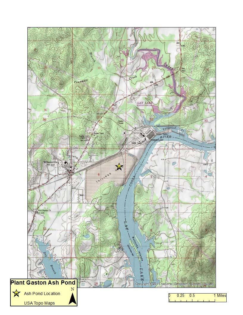
1 HISTORY OF CONSTRUCTION FOR EXISTING CCR SURFACE IMPOUNDMENT PLANT GASTON ASH POND 40 CFR (c)(1)(i) (xii) (i) Site Name and Ownership Information: Site Name: E.C. Gaston Steam Plant Site Location: Wilsonville, Alabama Site Address: Highway 25 Wilsonville, Alabama Owner: Owner Address: Alabama Power Company 600 North 18 th Street Birmingham, AL CCR Impoundment Name: NID ID: Plant Gaston Ash Pond N/A EPA s Disposal of Coal Combustion Residuals from Electric Utilities Final Rule (40 C.F.R. Part 257 and Part 261), (c)(1), requires the owner or operator of an existing CCR surface impoundment to compile a history of construction. To the extent feasible, the following information is provided: (ii) CCR Unit Location Map: 33 14'02"N, 86 28'22"W See Location Map in the Appendix (iii) Purpose of CCR Impoundment: The E.C. Gaston Steam Plant is a 5 unit electric generating facility; Units 1 4 were originally coal fired units but are were recently converted to gas fired units with the ability to be coal fired, while Unit 5 remains a coal fired only. The Plant Gaston Ash Pond is designed to receive and store coal combustion residuals produced during the electric generating process at Plant Gaston, along with low volume wastes and stormwater sump flows from the plant. (iv) Watershed Description: Plant Gaston is located within both the Lower Yellowleaf Creek HUC 12 watershed which has a total area of 29,120 acres and the Hay Spring Branch HUC 12 watershed which has a total area of 27,197 acres. The ash pond unit is located entirely within the Hay Spring Branch watershed. Both the Lower Yellowleaf Creek and Hay Spring Branch watersheds are located within within the Lower Coosa HUC 8 watershed which has a drainage area of 1,255,891 acres. Only a relatively nominal portion of flow from the surrounding watershed flows into the pond. (v) Description of physical and engineering properties of CCR impoundment foundation/abutments:
2 The foundation soils beneath the impoundment are comprised of residuum of dolomite, limestone and shale, typically classified as highly plastic clays and silty clays. Bedded chert and chert boulders are encountered in some areas. Based on borings conducted prior to construction of the impoundment, the elevation of the top of the underlying bedrock ranges from 380 feet to 410 feet (approx.). The geologic properties of the site are characterized by carbonate rocks of the Knox Group of the Cambrian and Ordovician age. When weathered, the carbonate rocks can yield cherty residual clay or incipient karst type topography. Visible karst topography has not been noted within the ash pond. (vi) Summary of Site Preparation and Construction Activities: The Ash Pond was originally constructed in the early 1950 s. The basin was formed by excavating predetermined zones to elevations ranging from 389 ft to 418 ft, with much of the center zone having no excavation. Maximum elevations in the center zone were approximately 420 ft. Material for the embankment construction was excavated from within the ash pond area adjacent to the embankments. The dike fill material consists mainly of clay. The depth of the fill extends up to depths of approximately 50 feet at its deepest. The South Dike was constructed at an elevation of 445 ft, but has been raised as high as 449 ft in some areas. It has a maximum height of approximately 50 feet. The West Dike was constructed at an elevation of 445 ft with a maximum height of 30 ft. The North Dike was constructed at elevations up to 445 ft, with later raises bringing it to a maximum elevation of 447 ft. It has a maximum height of 25 ft. The exterior slopes are 2.5:1 on the east dike and 2:1 on the west and north dikes. The interior slopes are 2.5:1 on the east dike and 1.5:1 on the west and north dikes. Efforts to widen the dikes have included adding fill to the slopes to maintain their original geometry. In the late 1980 s, the impoundment was reconfigured to the arrangement that is currently used (see Appendix). Ash is sluiced into one of two settling ponds located at the eastern edge of the pond. When one cell fills, the sluice is diverted to the alternate cell while the filled cell is dredged. The dredged ash is conditioned and dry stacked further west in the pond. The sluice water, after leaving the settling pond, is diverted to a canal that runs along the perimeter of the pond boundary to another low energy area at the western pond edge where further settling of fines takes place. From there, the water enters another canal which leads to the discharge structure located at the Coosa River. Additional construction undertaken since the initial efforts in the 1950 s include widening of the dike, especially along the eastern edge of the pond. The widening to its current geometry was achieved by adding a layer of clay to the downstream face of the dike, and by adding fill material to the sluiced ash on the upstream side. This resulted in a dike raise of up to four feet in some areas. The area between the northeastern dike slope and the dike built to comprise the western edge of the coal pile was also filled over the years. The fill is comprised of miscellaneous soils including clays, gravelly clays and silts, and isolated boulders.
3 (vii) Engineering Diagram: The following drawings reflecting the construction of the Plant Gaston Ash Pond can be found in the Appendix: Typical Section South Dike Typical Section North and West Dikes Typical Section Adjacent to Coal Pile 2000 Ash Stacking Plan 2013 Ash Pond Topo (viii) Description of Instrumentation: The Plant Gaston Ash Pond has no instrumentation. (ix) Area capacity curves: Cumulative Volume in Acre Feet Plant Gaston Ash Pond Area Capacity Curve Elevation of Pond in Feet (NAVD) Surface Area in Acres Acre Feet Acres (x) Spillway/Diversion design features and capacity calculations: Sluiced flows enter the ash pond, along with plant stormwater runoff and low volume wastes, and rain water that falls directly on the pond. There is also a limited amount of run on from adjoining watershed areas that enters the pond near the southwest corner. Rainfall runoff collects in a stormwater settling pond at the northwest corner of the impoundment, while the sluiced flows enter into one of two ash containment areas. These ponds are utilized alternately while dredging operations are performed on the cell not in use. Water then is routed from the stormwater pond and the ash containment areas through a series of canals until it reaches a decant area at the southwestern end of the ash pond. Water is then released into another
4 long canal until it reaches the main outlet structure. The outlet structure consists of an approximately 8 foot riser with an invert elevation of approximately 409 ft. The riser connects to the 36 in spillway pipe that discharges from the ash pond. The ash pond has present water capacity of about 22,036,000 cubic feet above the normal operating level, based on the 2013 topographical survey. The design storm for the Plant Gaston Ash Pond is the PMP. The rainwater volume during a PMP/24 hour design rainfall event is 1,384 acre ft. The excess water capacity remaining after a 100 year/24 hour event is 104 acre ft. The normal pool at the outlet is approximately Elev. 432 ft. After a PMP/24 hour event, water will overtop the embankment elevation of 444 ft. At the overtopping elevation of EL 444 ft, the spillway is capable of discharging 173 cfs. (xi) Provisions for surveillance, maintenance and repair: Inspections of dams and dikes are critical components and are conducted on a regular basis at least annually by professional dam safety engineers and at a minimum interval of every seven days by qualified persons at the plant. In addition, inspections are performed after unusual events such as storms. The inspections provide assurance that structures are sound and that action is taken, as needed, based on the findings. Safety inspections include numerous checklist items. Specific items vary from site to site but may include observations of such things as pond levels, weather conditions, rainfall since the prior inspection, conditions of slopes and drains, erosion, animal damage, ant hills, alignment of retaining structures and more. Dam safety engineers inspect any maintenance or remediation performed since the previous inspection, check the status of work recommended at prior inspections, ensure that the posting of emergency notification information is up to date and evaluate any items noted during plant personnel inspections. Construction specifications: Design cross sections are presented in the Appendix. (xii) Known record of structural instability: There are no known instances of structural instability at the CCR unit.
5 Appendix
6
7 Typical Section South Dike Typical Section North and West Dikes Typical Section Adjacent to Coal Pile
8
9 Alabama Power Company
HISTORY OF CONSTRUCTION FOR EXISTING CCR SURFACE IMPOUNDMENT PLANT GADSDEN ASH POND 40 CFR (c)(1)(i)-(xii)
(1)(i)-(xii)") HISTORY OF CONSTRUCTION FOR EXISTING CCR SURFACE IMPOUNDMENT PLANT GADSDEN ASH POND 40 CFR 257.73(c)(1)(i)-(xii) (i) Site Name and Ownership Information: Site Name: Site Location: Site Address: Gadsden
HISTORY OF CONSTRUCTION FOR EXISTING CCR SURFACE IMPOUNDMENT PLANT GADSDEN ASH POND 40 CFR 257.73(c)(1)(i)-(xii) (i) Site Name and Ownership Information: Site Name: Site Location: Site Address: Gadsden
STRUCTURAL STABILITY ASSESSMENT
 STRUCTURAL STABILITY ASSESSMENT CFR 257.73(d) Bottom Ash Pond Complex Cardinal Plant Brilliant, Ohio October, 2016 Prepared for: Cardinal Operating Company Cardinal Plant Brilliant, Ohio Prepared by: Geotechnical
INFLOW DESIGN FLOOD CONTROL SYSTEM PLAN 40 C.F.R. PART PLANT YATES ASH POND 2 (AP-2) GEORGIA POWER COMPANY
 GEORGIA POWER COMPANY") INFLOW DESIGN FLOOD CONTROL SYSTEM PLAN 40 C.F.R. PART 257.82 PLANT YATES ASH POND 2 (AP-2) GEORGIA POWER COMPANY EPA s Disposal of Coal Combustion Residuals from Electric Utilities Final Rule (40 C.F.R.
INFLOW DESIGN FLOOD CONTROL SYSTEM PLAN 40 C.F.R. PART 257.82 PLANT YATES ASH POND 2 (AP-2) GEORGIA POWER COMPANY EPA s Disposal of Coal Combustion Residuals from Electric Utilities Final Rule (40 C.F.R.
ENGINEER S CERTIFICATION OF FAULT AREA DEMONSTRATION (40 CFR )
") PLATTE RIVER POWER AUTHORITY RAWHIDE ENERGY STATION BOTTOM ASH TRANSFER (BAT) IMPOUNDMENTS LARIMER COUNTY, CO ENGINEER S CERTIFICATION OF FAULT AREA DEMONSTRATION (40 CFR 257.62) FOR COAL COMBUSTION RESIDUALS
PLATTE RIVER POWER AUTHORITY RAWHIDE ENERGY STATION BOTTOM ASH TRANSFER (BAT) IMPOUNDMENTS LARIMER COUNTY, CO ENGINEER S CERTIFICATION OF FAULT AREA DEMONSTRATION (40 CFR 257.62) FOR COAL COMBUSTION RESIDUALS
CCR Rule Annual Inspection Report (cont.) 2
 2") The inspection findings consisted of maintenance items and items that were not observed to be signs or potential signs of significant structural weakness. No deficiencies or disrupting conditions that
The inspection findings consisted of maintenance items and items that were not observed to be signs or potential signs of significant structural weakness. No deficiencies or disrupting conditions that
Big Rivers Electric Corporation Disposal of Coal Combustion Residuals (CCR) from Electric Utilities Final Rule CCR Impoundment Liner Assessment Report
 from Electric Utilities Final Rule CCR Impoundment Liner Assessment Report") Big Rivers Electric Corporation Disposal of Coal Combustion Residuals (CCR) from Electric Utilities Final Rule CCR Impoundment Liner Assessment Report CCR Surface Impoundment Information Name: Operator:
Big Rivers Electric Corporation Disposal of Coal Combustion Residuals (CCR) from Electric Utilities Final Rule CCR Impoundment Liner Assessment Report CCR Surface Impoundment Information Name: Operator:
Mr. Michael Malone CPS Energy 145 Navarro Street San Antonio, Texas Project No
 January 17, 2018 Mr. Michael Malone 145 Navarro Street San Antonio, Texas 78205 Project No. 0337367 Environmental Resources Management CityCentre Four 840 West Sam Houston Pkwy N. Suite 600 Houston, Texas
Sediment Trap. A temporary runoff containment area, which promotes sedimentation prior to discharge of the runoff through a stabilized spillway.
 Sediment Trap SC-15 Source: Caltrans Construction Site Best Management Practices Manual, 2003. Description A temporary runoff containment area, which promotes sedimentation prior to discharge of the runoff
Location Restriction Demonstration
 Location Restriction Demonstration R.M. Heskett Station Coal Ash Landfill Prepared for Montana-Dakota Utilities Company October 2018 Minneapolis, MN, Bismarck, ND Location Restrictions Demonstration October
design, construction, operation, and maintenance of the BAP is consistent with recognized and generally accepted good engineering standards.
 design, construction, operation, and maintenance of the BAP is consistent with recognized and generally accepted good engineering standards. In addition to the field inspection, Associated Engineers, Inc.
Sediment Trap. At multiple locations within the project site where sediment control is needed.
 Sediment Trap SE-3 Objectives EC Erosion Control SE Sediment Control TR Tracking Control WE Wind Erosion Control Non-Stormwater NS Management Control Waste Management and WM Materials Pollution Control
J.H. Campbell Generating Facility Pond A - Location Restriction Certification Report
 J.H. Campbell Generating Facility Pond A - Location Restriction Certification Report Pursuant to: 40 CFR 257.60 40 CFR 257.61 40 CFR 257.62 40 CFR 257.63 40 CFR 257.64 Submitted to: Consumers Energy Company
CCR Surface Impoundment Location Restrictions Demonstration. MidAmerican Energy Company, Louisa Generating Station
 CCR Surface Impoundment Location Restrictions Demonstration MidAmerican Energy Company, Louisa Generating Station Final October 17, 2018 CCR Surface Impoundment Location Restrictions Demonstration Prepared
LOCATED IN INDIAN RIVER COUNTY PREPARED FOR S.J.R.W.M.D. AND F.W.C.D. DECEMBER, 2003 Updated 2007 Updated May 2014 PREPARED BY
 FELLSMERE WATER CONTROL DISTRICT EAST MASTER DRAINAGE PLAN AND STORMWATER HYDROLOGIC ANALYSIS OF THE GRAVITY DRAINAGE SYSTEM LOCATED BETWEEN THE EAST BOUNDARY, LATERAL U, THE MAIN CANAL, AND DITCH 24 LOCATED
Standards for Soil Erosion and Sediment Control in New Jersey May 2012
 STANDARD FOR SEDIMENT BASIN Definition A barrier, dam, excavated pit, or dugout constructed across a waterway or at other suitable locations to intercept and retain sediment. Basins created by construction
BRANDON LAKES AVENUE PRE AND POST CONDITIONS DRAINAGE REPORT
 BRANDON LAKES AVENUE PRE AND POST CONDITIONS DRAINAGE REPORT Hillsborough County Public Works County Center, 22nd Floor 601 E. Kennedy Blvd. Tampa, FL 33602 BRANDON LAKES AVENUE DRAINAGE IMPROVEMENTS Capital
Suitable Applications Sediment traps should be considered for use:
 Categories EC Erosion Control SE Sediment Control TC Tracking Control WE Wind Erosion Control Non-Stormwater NS Management Control Waste Management and WM Materials Pollution Control Legend: Primary Objective
[1] Performance of the sediment trap depends on the type of outlet structure and the settling pond surface area.
![[1] Performance of the sediment trap depends on the type of outlet structure and the settling pond surface area.](/thumbs/76/74245181.jpg "[1] Performance of the sediment trap depends on the type of outlet structure and the settling pond surface area.") Sediment Trench SEDIMENT CONTROL TECHNIQUE Type 1 System Sheet Flow Sandy Soils Type 2 System [1] Concentrated Flow Clayey Soils Type 3 System [1] Supplementary Trap Dispersive Soils [1] Performance of
Sediment Trench SEDIMENT CONTROL TECHNIQUE Type 1 System Sheet Flow Sandy Soils Type 2 System [1] Concentrated Flow Clayey Soils Type 3 System [1] Supplementary Trap Dispersive Soils [1] Performance of
Stone Outlet Sediment Trap
 3.12 Sediment Control Description: A stone outlet sediment trap is a small detention area formed by placing a stone embankment with an integral stone filter outlet across a drainage swale for the purpose
Report for Area Drainage Studies for 1320 MW (2x660 MW) THERMAL POWER PROJECT AT MIRZAPUR, U.P.
 THERMAL POWER PROJECT AT MIRZAPUR, U.P.") Report for Area Drainage Studies for 1320 MW (2x660 MW) THERMAL POWER PROJECT AT MIRZAPUR, U.P. 1. Introduction M/s Welspun Energy Uttar Pradesh Ltd. (WEUPL) is putting up 1320 MW (2 x 660 MW) coal fired
Report for Area Drainage Studies for 1320 MW (2x660 MW) THERMAL POWER PROJECT AT MIRZAPUR, U.P. 1. Introduction M/s Welspun Energy Uttar Pradesh Ltd. (WEUPL) is putting up 1320 MW (2 x 660 MW) coal fired
ENTERGY INDEPENDENCE PLANT EAST AND WEST RECYCLE PONDS DEMONSTRATION OF COMPLIANCE WITH EPA CCR RULE SITING CRITERIA , FAULT AREAS.
 ENTERGY INDEPENDENCE PLANT EAST AND WEST RECYCLE PONDS DEMONSTRATION OF COMPLIANCE WITH EPA CCR RULE SITING CRITERIA 257.62, FAULT AREAS Prepared for Entergy Arkansas, Inc. PO Box 551 Little Rock, AR 72203
Sediment Control Practices. John Mathews Ohio Dept. of Natural Resources, Division of Soil and Water Resources
 Sediment Control Practices John Mathews Ohio Dept. of Natural Resources, Division of Soil and Water Resources Practices Treat the Largest Soil Particles Sand Sand Silt Clay Treated Untreated Settleable
3.0 SUMMARY OF FINDINGS
 AECOM 500 W Jefferson St. Suite 1600 Louisville, KY 40202 www.aecom.com 502-569-2301 tel 502-569-2304 fax October 17, 2018 Big Rivers Electric Corporation Sebree Generating Station 9000 Highway 2096 Robards,
Rock & Aggregate Drop Inlet Protection
 Rock & Aggregate Drop Inlet Protection SEDIMENT CONTROL TECHNIQUE Type 1 System Sheet Flow Sandy Soils Type 2 System [1] Concentrated Flow Clayey Soils Type 3 System Supplementary Trap Dispersive Soils
ENTERGY WHITE BLUFF PLANT RECYCLE POND A AND RECYCLE POND B DEMONSTRATION OF COMPLIANCE WITH EPA CCR RULE SITING CRITERIA 257.
 ENTERGY WHITE BLUFF PLANT RECYCLE POND A AND RECYCLE POND B DEMONSTRATION OF COMPLIANCE WITH EPA CCR RULE SITING CRITERIA 257.62, FAULT AREAS Prepared for Entergy Arkansas, Inc. PO Box 551 Little Rock,
Emergency Action Plan (EAP) Tata Pond Dam
 Tata Pond Dam") For Official Use Only Not for Public Distribution 02/03/16 Emergency Action Plan (EAP) Tata Pond Dam State of Connecticut Dam ID: 0000 Town or City, County, Connecticut Name of Dam Owner Dam Hazard Classification
For Official Use Only Not for Public Distribution 02/03/16 Emergency Action Plan (EAP) Tata Pond Dam State of Connecticut Dam ID: 0000 Town or City, County, Connecticut Name of Dam Owner Dam Hazard Classification
Coal Combustion Residuals Unit Inflow Design Flood Control System Plan
 Coal Combustion Residuals Unit Inflow Design Flood Control System Plan Virginia Electric and Power Company Chesterfield Power Station Upper (East) Pond Chesterfield County, Virginia GAI Project Number:
HISTORY OF CONSTRUCTION W.H. Sammis Coal Plant North and South Ponds Stratton, Ohio
 Prepared for: FirstEnergy Generation, LLC 76 South Main St Akron, OH 44308 HISTORY OF CONSTRUCTION Stratton, Ohio Prepared by: 10211 Wincopin Circle, Floor 4 Columbia, Maryland 21044 17 October 2016 pdf
CASE STUDY #9 - Brushy Fork Dam, Sugar Grove, West Virginia
 CASE STUDY #9 - Brushy Fork Dam, Sugar Grove, West Virginia Brushy Fork Dam is a flood control structure built by the Soil Conservation Service southeast of the city of Franklin in Pendleton County, West
Chapter 5 CALIBRATION AND VERIFICATION
 Chapter 5 CALIBRATION AND VERIFICATION This chapter contains the calibration procedure and data used for the LSC existing conditions model. The goal of the calibration effort was to develop a hydraulic
THE MINISTRY OF ENERGY AND ENERGY INDUSTRIES MINERALS DIVISION MINE DESIGN TEMPLATE OPERATOR NAME: OPERATOR ADDRESS: PHONE NUMBER: FACSIMILE:
 THE MINISTRY OF ENERGY AND ENERGY INDUSTRIES MINERALS DIVISION MINE DESIGN TEMPLATE 1.0 GENERAL INFORMATION OPERATOR NAME: OPERATOR ADDRESS: PHONE NUMBER: FACSIMILE: NAME OF CONTACT: CELLULAR PHONE: EMAIL
Stage Discharge Tabulation for Only Orifice Flow
 Stage Discharge Tabulation for Only Orifice Flow DEPTH STAGE DISCHARGE (meters) (feet) (meters) (feet) (m 3 /s) (ft 3 /s) 0 0.20 0.40 0.60 0.80 1.00 1.20 1.40 1.60 1.80 2.00 0.7 1.3 2.0 2.6 3.3 3.9 4.6
PENNSYLVANIA DEPARTMENT OF TRANSPORTATION ENGINEERING DISTRICT 3-0
 PENNSYLVANIA DEPARTMENT OF TRANSPORTATION ENGINEERING DISTRICT 3-0 LYCOMING COUNTY S.R.15, SECTION C41 FINAL HYDROLOGIC AND HYDRAULIC REPORT STEAM VALLEY RUN STREAM RELOCATION DATE: June, 2006 REVISED:
STREUVER FIDELCO CAPPELLI, LLC YONKERS DOWNTOWN DEVELOPMENT PHASE 1. DRAFT ENVIRONMENTAL IMPACT STATEMENT For: PALISADES POINT
 STREUVER FIDELCO CAPPELLI, LLC YONKERS DOWNTOWN DEVELOPMENT PHASE 1 DRAFT ENVIRONMENTAL IMPACT STATEMENT For: PALISADES POINT Prepared by: PAULUS, SOKOLOWSKI & SARTOR STORMWATER MANAGEMENT 1. Methodology
APPENDIX B DESIGN CRITERIA FOR TEMPORARY WATER QUALITY BMPS USED DURING CONSTRUCTION
 APPENDIX B DESIGN CRITERIA FOR TEMPORARY WATER QUALITY BMPS USED DURING CONSTRUCTION This Appendix presents design criteria and example calculations for the following temporary water quality BMPs for use
KRIS wsbssm. IBHiiilll
 KRIS wsbssm IBHiiilll Digitized by the Internet Archive in 2012 with funding from University of Illinois Urbana-Champaign http://archive.org/details/engineeringaspec34ekbl STATE OF ILLINOIS HENRY HORNER,
THE NEED FOR AN ADDITIONAL SPILLWAY AT THE SANFORD DAM BOILING SPRING LAKES, NC. Presentation for The Brunswick County Commissioners April 20, 2015
 THE NEED FOR AN ADDITIONAL SPILLWAY AT THE SANFORD DAM BOILING SPRING LAKES, NC Presentation for The Brunswick County Commissioners April 20, 2015 The Sanford Dam Earth Dam constructed in 1961 Drainage
Name: Mid-Year Review #2 SAR
 Name: Mid-Year Review #2 SAR Base your answers to questions 1 through 3 on on the diagram below, which shows laboratory materials used for an investigation of the effects of sediment size on permeability,
APPENDIX B WORKSHEETS & EXHIBITS
 APPENDIX B WORKSHEETS & EXHIBITS A worksheet provides the designer a representation of a measure that allows for input of specific design criteria. The plan designer will be required to assess field conditions
3.0 SUMMARY OF FINDINGS
 AECOM 500 W Jefferson St. Suite 1600 Louisville, KY 40202 www.aecom.com 502-569-2301 tel 502-569-2304 fax October 17, 2018 Big Rivers Electric Corporation Sebree Generating Station 9000 Highway 2096 Robards,
3.18 GEOLOGY AND SOILS
 3.18 GEOLOGY AND SOILS This section discusses geologic resource concerns as they relate to the environment, public safety, and project design both during construction and after completion of the project.
Geosynthetics Applications and Performance Reviews Select Case Histories
 Geosynthetics Applications and Performance Reviews Select Case Histories Debora J. Miller, Ph.D., P.E.; Dean B. Durkee,, Ph.D., P.E.; Michael A. Morrison, P.E., David B. Wilson, P.E., and Kevin Smith,
1 PROJECT BACKGROUND. August 14, Alberta Transportation Central Region #401, Street Red Deer, Alberta T4N 6K8
 August 14, 2013 Alberta Transportation Central Region #401, 4902 51 Street Red Deer, Alberta T4N 6K8 Mr. Dennis Grace, P.Eng. Construction Engineer Dear Mr. Grace: Central Region Geohazard Assessment 2013
Background. Valley fills Sites in the Area. Construction over Mine Spoil Fills
 Construction over Mine Spoil Fills Wayne A. Karem, PhD, PE, PG, D.GE 2014 KSPE Annual Conference Background Strip mining; mountaintop and contour mining Creates huge quantities of mine spoil The mine spoil
Type 1 System Sheet Flow Sandy Soils Type 2 System Concentrated Flow Clayey Soils Type 3 System [1] Supplementary Trap Dispersive Soils
![Type 1 System Sheet Flow Sandy Soils Type 2 System Concentrated Flow Clayey Soils Type 3 System [1] Supplementary Trap Dispersive Soils](/thumbs/77/76519623.jpg "Type 1 System Sheet Flow Sandy Soils Type 2 System Concentrated Flow Clayey Soils Type 3 System [1] Supplementary Trap Dispersive Soils") Sediment Weirs SEDIMENT CONTROL TECHNIQUE Type 1 System Sheet Flow Sandy Soils Type 2 System Concentrated Flow Clayey Soils Type 3 System [1] Supplementary Trap Dispersive Soils [1] Type 3 classification
Sediment Weirs SEDIMENT CONTROL TECHNIQUE Type 1 System Sheet Flow Sandy Soils Type 2 System Concentrated Flow Clayey Soils Type 3 System [1] Supplementary Trap Dispersive Soils [1] Type 3 classification
WATER MANAGEMENT REPORT FOR PAGE ESTATES
 WATER MANAGEMENT REPORT FOR PAGE ESTATES SLB Consulting of SW Florida, LLC PO Box 2826 Bonita Springs, FL. 34133 Phone: 239-948-9566 sandra@slbconsult.com C.O.A. # 25395 September 1, 2014 Sandra L. Bottcher
Little Swan Lake. Dam Inspection & Siltation Study Prepared By: William Klingner, P.E., CFM October 28, 2018
 Little Swan Lake Dam Inspection & Siltation Study Prepared By: William Klingner, P.E., CFM October 28, 2018 Agenda Little Swan Lake Dam Inspection Theoretical Little Swan Lake Siltation Rate Calculations
NORTHUMBERLAND COUNTY, PA
 QUAKER RUN Stream and Wetland Restoration As-Built Completion Report and First Year Monitoring Data Coal Township NORTHUMBERLAND COUNTY, PA Upstream Before Upstream After Prepared for: COAL TOWNSHIP 805
FLOOD REPORT FOR MANITOBA. June 28, A Gale wind warning is in effect for Lake Manitoba and Lake Winnipeg
 FLOOD REPORT FOR MANITOBA June 28, 2014 A Gale wind warning is in effect for Lake Manitoba and Lake Winnipeg Flood Warning*: Flood Watch*: High Water Advisory*: - Assiniboine River, from Shellmouth Dam
Materials. Use materials meeting the following.
 208.01 Section 208. SOIL EROSION AND SEDIMENTATION CONTROL 208.01 Description. Install and maintain erosion and sedimentation controls to minimize soil erosion and to control sedimentation from affecting
Status Report on Polychlorinated Biphenyls in the Western Storm Drain University of California, Richmond Field Station Richmond, California
 Status Report on Polychlorinated Biphenyls in the Western Storm Drain University of California, Richmond Field Station Richmond, California Introduction Beginning in 1999, the University of California,
DESIGN OF WASTE DUMPS WITH FLOW-THROUGH ROCK DRAINS by Peter C. Lighthall, C. David Sellars, and W.D. Burton ABSTRACT
 ABSTRACT DESIGN OF WASTE DUMPS WITH FLOW-THROUGH ROCK DRAINS by Peter C. Lighthall, C. David Sellars, and W.D. Burton A number of mines in mountainous regions of British Columbia are being forced by topographic
GEOPHYSICAL IMAGING TO ENHANCE ANALYSIS, DESIGN AND DRILLING OF LARGE-SCALE GEOTHERMAL SYSTEMS. Abstract
 GEOPHYSICAL IMAGING TO ENHANCE ANALYSIS, DESIGN AND DRILLING OF LARGE-SCALE GEOTHERMAL SYSTEMS John A. Mundell, Mundell & Associates, Inc., Indianapolis, Indiana Gabriel Hebert, Mundell & Associates, Inc.,
CHAPTER GEOLOGICALLY HAZARDOUS AREAS Applicability Regulations.
 CHAPTER 19.07 GEOLOGICALLY HAZARDOUS AREAS 19.07.010 Applicability. Geologically hazardous areas may pose a threat to the health and safety of citizens when incompatible development is sited in areas of
APPENDIX B HYDROLOGY
 APPENDIX B HYDROLOGY TABLE OF CONTENTS 1.0 INTRODUCTION... 1 2.0 PROBABLE MAXIMUM PRECIPITATION (PMP)... 1 3.0 DESIGN FLOW CALCULATION... 1 4.0 DIVERSION CHANNEL SIZING... 2 5.0 REFERENCES... 4 LIST OF
STORMWATER REPORT FRITO LAY SUBDIVISION NO. 3
 STORMWATER REPORT FRITO LAY SUBDIVISION NO. 3 May 2018 STORMWATER REPORT I. Subdivision Data a. The parcel is adjacent to the existing Frito Lay property in Topeka; and the subject plat application encompasses
WQ Outlet Design Single Orifice Orifice diameter = 24. Perforated riser/orifice Plate Outlet area per perforation row = 4
 These calculations should be used when designing the outlet structures for extended wet and dry detention basins (Sections 4. 7 and 4.8). The water quality outlet size and the trash rack design will vary
Pierce County Department of Planning and Land Services Development Engineering Section
 Page 1 of 7 Pierce County Department of Planning and Land Services Development Engineering Section PROJECT NAME: DATE: APPLICATION NO.: PCDE NO.: LANDSLIDE HAZARD AREA (LHA) GEOLOGICAL ASSESSMENT REPORT
APPENDIX G APPENDIX G SEDIMENT CONTAINMENT SYSTEM DESIGN RATIONALE
 APPENDIX G SEDIMENT CONTAINMENT SYSTEM DESIGN RATIONALE March 18, 2003 This page left blank intentionally. March 18, 2003 G-2 FIGURES Page # Figure G.1 Estimated Runoff from Precipitation Over Different
APPENDIX E GREATER SPRINGFIELD RELIABILTIY PROJECT DRAINAGE ANALYSIS FOR THE NEWGATE/PHELPS ROAD AND THE HATCHETT HILL ROAD AREAS
 APPENDIX E GREATER SPRINGFIELD RELIABILTIY PROJECT DRAINAGE ANALYSIS FOR THE NEWGATE/PHELPS ROAD AND THE HATCHETT HILL ROAD AREAS New England East-West Solution (NEEWS) Greater Springfield Reliability
FOR PROJECTS INITIATED AFTER NOVEMBER 1, 2008 ITEM 716 EMBANKMENT EARTH OUTLET SEDIMENT TRAP
 AFTER NOVEMBER 1, 2008 ITEM 716 EMBANKMENT EARTH OUTLET SEDIMENT TRAP 716.1 Description. This work shall consist of furnishing, installing, maintaining, and removing temporary erosion protection and sediment
Rucker Pond. Background
 Rucker Pond Background The Rucker Basin consists of two subbasins (East and West) that drain to a single area known as Rucker Pond. Both subbasins have the same hydraulic parameters, but have different
June 9, R. D. Cook, P.Eng. Soils Engineer Special Services Western Region PUBLIC WORKS CANADA WESTERN REGION REPORT ON
 PUBLIC WORKS CANADA WESTERN REGION REPORT ON GEOTECHNICAL INVESTIGATION PROPOSED MARTIN RIVER BRIDGE MILE 306.7 MACKENZIE HIGHWAY Submitted by : R. D. Cook, P.Eng. Soils Engineer Special Services Western
Continuing Education Associated with Maintaining CPESC and CESSWI Certification
 Continuing Education Associated with Maintaining CPESC and CESSWI Certification Module 2: Stormwater Management Principles for Earth Disturbing Activities Sponsors: ODOTs Local Technical Assistance Program
Assessment of Lake Forest Lake Sediment Trapping Efficiency and Capacity. Marlon R. Cook Groundwater Assessment Program Geological Survey of Alabama
 Assessment of Lake Forest Lake Sediment Trapping Efficiency and Capacity Marlon R. Cook Groundwater Assessment Program Geological Survey of Alabama Impacts of the Lake at Lake Forest on the connectivity
Why Geomorphology for Fish Passage
 Channel Morphology - Stream Crossing Interactions An Overview Michael Love Michael Love & Associates mlove@h2odesigns.com (707) 476-8938 Why Geomorphology for Fish Passage 1. Understand the Scale of the
CITY OF CAPE CORAL STORMWATER MASTER PLAN PHASE II - PART 1 BASINS 4, 10, & 14 SUB-BASIN DRAINAGE IMPROVEMENTS HYDRAULIC ANALYSIS SUMMARY
 CITY OF CAPE CORAL STORMWATER MASTER PLAN PHASE II - PART 1 BASINS 4, 10, & 14 SUB-BASIN DRAINAGE IMPROVEMENTS HYDRAULIC ANALYSIS SUMMARY Cape Coral, FL Prepared for: The City of Cape Coral Public Works
R.M.HARW & ASSOCIATES LTD. GEOTECHNICAL INVESTIGATION PROPOSED BRIDGE SITE. HELAVA CREEKl MILE MACKENZIE HIGHWAY E-2510 OCTOBER 16, 1973
 El R.M.HARW & ASSOCIATES LTD. GEOTECHNICAL INVESTIGATION PROPOSED BRIDGE SITE HELAVA CREEKl MILE 616.4 MACKENZIE HIGHWAY E-2510 OCTOBER 16, 1973 R,M,HARDV & ASSOCIATES LTD. CONSULTING ENGINEERING & TESTING
VIRGINIA ELECTRIC AND POWER COMPANY CHESTERFIELD POWER STATION LOWER ASH POND CHESTERFIELD COUNTY, VIRGINIA
 Prepared for Dominion 5000 Dominion Boulevard Glen Allen, Virginia 23060 EMERGENCY ACTION PLAN VIRGINIA ELECTRIC AND POWER COMPANY CHESTERFIELD POWER STATION LOWER ASH POND CHESTERFIELD COUNTY, VIRGINIA
Highland Lake Bathymetric Survey
 Highland Lake Bathymetric Survey Final Report, Prepared For: The Town of Highland Lake 612 Lakeshore Drive Oneonta, AL 35121 Prepared By: Tetra Tech 2110 Powers Ferry Road SE Suite 202 Atlanta, GA 30339
Attachment B to Technical Memorandum No.2. Operations Plan of Ross Valley Detention Basins
 Attachment B to Technical Memorandum No.2 Operations Plan of Ross Valley Detention Basins Operations Plan of Ross Valley Detention Basins Stetson Engineers Inc. January 26, 2011 1.0 Introduction Achieving
Stream Simulation: A Simple Example
 Stream Simulation: A Simple Example North Thompson Creek, CO Paul T. Anderson U.S.D.A. Forest Service Here s How We Started May 2011 2-1 USDA-Forest Service Here s How We Finished Forest Service Aquatic
TSEGI WASH 50% DESIGN REPORT
 TSEGI WASH 50% DESIGN REPORT 2/28/2014 Daniel Larson, Leticia Delgado, Jessica Carnes I Table of Contents Acknowledgements... IV 1.0 Project Description... 1 1.1 Purpose... 1 Figure 1. Erosion of a Headcut...
FRED BURR DAM FEASIBILITY STUDY
 FRED BURR DAM FEASIBILITY STUDY Fred Burr Dam Feasibility Study Purpose: Develop pre-feasibility risk reduction alternatives and recommendations for short-term operations and long-term rehabilitation.
Woodford County Erosion Prevention Plan and Permit. Application #
 Woodford County Erosion Prevention Plan and Permit Application # Date Instructions: Applicant will complete Parts A and B, and attach a proposed site diagram. This diagram must be completed in accordance
Continuing Education Course #101 Drainage Design with WinTR-55
 1 of 5 Continuing Education Course #101 Drainage Design with WinTR-55 1. WinTR-55 uses the Kinematic Wave method for calculating storm runoff rates and volumes. 2. According to the Velocity Method, the
1.0 INSPECTION ANNUAL INSPECTION, JUNE 29, 2011 CARMACKS COPPER PROJECT, CARMACKS, YUKON. Dear Mr. West-Sells,
 Doc. No. 162 Rev. 0 Mr. Paul West-Sells President & Chief Operating Officer Western Copper Corporation 2060-1111 West Georgia Street Vancouver, BC V6E 4M3 ANNUAL INSPECTION, JUNE 29, 2011 CARMACKS COPPER
Coarse Sediment Traps
 Coarse Sediment Traps SEDIMENT CONTROL TECHNIQUE Type 1 System Sheet Flow Sandy Soils Type 2 System [1] Concentrated Flow Clayey Soils [2] Type 3 System Supplementary Trap Dispersive Soils [1] Though primarily
MIDDLESEX COUNTY Department of Planning and Community Development P.O. Box 427, Saluda, VA Phone: Fax:
 MIDDLESEX COUNTY Department of Planning and Community Development P.O. Box 427, Saluda, VA 23149 Phone: 804-758-3382 Fax: 804-758-0061 LAND DISTURBANCE PERMIT SUBMISSION REQUIREMENTS In order to expedite
Sediment Weirs (Instream)
") Sediment Weirs (Instream) INSTREAM PRACTICES Flow Control No Channel Flow Dry Channels Erosion Control Low Channel Flows Shallow Water Sediment Control High Channel Flows [1] Deep Water [1] Sediment weirs
Sediment Weirs (Instream) INSTREAM PRACTICES Flow Control No Channel Flow Dry Channels Erosion Control Low Channel Flows Shallow Water Sediment Control High Channel Flows [1] Deep Water [1] Sediment weirs
B805 TEMPORARY EROSION AND SEDIMENT CONTROL MEASURES - OPSS 805
 B805 MEASURES - OPSS 805 805.1 GENERAL Construction activities frequently remove protective cover and expose soil to accelerated rates of erosion. Sediments generated thereby can be conveyed via runoff
Table 5-1 Sampling Program Summary for Milltown Ford Avenue Redevelopment Area, NJ.
 Table 5- Sampling Program Summary for Milltown Ford Avenue Redevelopment Area, NJ. Transformer Pads (9 pads: PAD 9) Evaluate if PCBs presently exist in soils adjacent to, and/or beneath the transformer
Hydrogeological Assessment for Part of Lots 2 and 3, Concession 5, Township of Thurlow, County of Hastings 1.0 INTRODUCTION. 1.
 February 10,2017 25506400 Ontario Ltd. Foxboro, ON Attention: Brad Newbatt Re: Hydrogeological Assessment for Part of Lots 2 and 3, Concession 5, Township of Thurlow, County of Hastings 1.0 INTRODUCTION
Water Management and Hydrology of Northeast Shark River Slough from 1940 to 2015
 Water Management and Hydrology of Northeast Shark River Slough from 1940 to 2015 Greater Everglades Ecosystem Restoration Conference April 2015 Kevin Kotun, Hydrologist Physical Resources Branch South
Submitted to: St. Johns River Power Park New Berlin Road Jacksonville, FL 32226
 RUN-ON/RUN-OFF CONTROL SYSTEM PLAN RUN-ON AND RUN-OFF CONTROL SYSTEM PLAN St. Johns River Power Park Byproduct Storage Area B Phase I Development Submitted to: St. Johns River Power Park 11201 New Berlin
LIQUEFACTION OF EARTH EMBANKMENT DAMS TWO CASE HISTORIES: (1) LIQUEFACTION OF THE EMBANKMENT SOILS, AND (2) LIQUEFACTION OF THE FOUNDATIONS SOILS
 LIQUEFACTION OF THE EMBANKMENT SOILS, AND (2) LIQUEFACTION OF THE FOUNDATIONS SOILS") LIQUEFACTION OF EARTH EMBANKMENT DAMS TWO CASE HISTORIES: (1) LIQUEFACTION OF THE EMBANKMENT SOILS, AND (2) LIQUEFACTION OF THE FOUNDATIONS SOILS Antonio Fernandez, Ph.D. 1 ABSTRACT Paul C. Rizzo Associates,
LIQUEFACTION OF EARTH EMBANKMENT DAMS TWO CASE HISTORIES: (1) LIQUEFACTION OF THE EMBANKMENT SOILS, AND (2) LIQUEFACTION OF THE FOUNDATIONS SOILS Antonio Fernandez, Ph.D. 1 ABSTRACT Paul C. Rizzo Associates,
Black Gore Creek 2013 Sediment Source Monitoring and TMDL Sediment Budget
 Black Gore Creek 2013 Sediment Source Monitoring and TMDL Sediment Budget Prepared for: Prepared By: - I. Introduction The Black Gore Creek Total Maximum Daily Load (TMDL) was developed in collaboration
3.12 Geology and Topography Affected Environment
 3 Affected Environment and Environmental Consequences 3.12 Geology and Topography 3.12.1 Affected Environment 3.12.1.1 Earthquakes Sterling Highway MP 45 60 Project Draft SEIS The Kenai Peninsula is predisposed
Swift Creek Sediment Management Action Plan (SCSMAP)
") Swift Creek Sediment Management Action Plan (SCSMAP) PHASE 2 PROJECT PLAN PROPOSAL Whatcom County Public Works Department 322 N. Commercial Street, Suite 210 Bellingham, WA 98225 (360) 676-6692 June 2013
Swift Creek Sediment Management Action Plan (SCSMAP) PHASE 2 PROJECT PLAN PROPOSAL Whatcom County Public Works Department 322 N. Commercial Street, Suite 210 Bellingham, WA 98225 (360) 676-6692 June 2013
Birecik Dam & HEPP Downstream River Arrangement R. Naderer, G. Scharler Verbundplan GmbH, 5021 Salzburg, Austria
 Birecik Dam & HEPP Downstream River Arrangement R. Naderer, G. Scharler Verbundplan GmbH, 5021 Salzburg, Austria e-mail: scharlerg@verbund.co.at Abstract Birecik Dam & HEPP on the Euphrates river in Turkey
Observations on Surface Water in the Seminary Fen in Spring, Prepared 6/4/13 by Sam Wetterlin; updated 7/28/13
 Observations on Surface Water in the Seminary Fen in Spring, 2013 Prepared 6/4/13 by Sam Wetterlin; updated 7/28/13 Ordinarily, a calcareous fen is primarily dependent on upwelling mineral-rich, oxygen-poor
EAGLES NEST AND PIASA ISLANDS
 EAGLES NEST AND PIASA ISLANDS HABITAT REHABILITATION AND ENHANCEMENT PROJECT MADISON AND JERSEY COUNTIES, ILLINOIS ENVIRONMENTAL MANAGEMENT PROGRAM ST. LOUIS DISTRICT FACT SHEET I. LOCATION The proposed
3.11 Floodplains Existing Conditions
 Other stormwater control practices may be needed to mitigate water quality impacts. In addition to detention facilities, other practices such as vegetated basins/buffers, infiltration basins, and bioswales
STUDY GUIDE FOR CONTENT MASTERY. Surface Water Movement
 Surface Water SECTION 9.1 Surface Water Movement In your textbook, read about surface water and the way in which it moves sediment. Complete each statement. 1. An excessive amount of water flowing downslope
ROCK EXCAVATION (GRADING) OPSS 206 INDEX
 OPSS 206 INDEX") 206-2 - OPSS 206 INDEX 206-2.1 GENERAL 206-2.1.1 Classification of Rock Materials 206-2.1.2 Tender Items 206-2.1.3 Other Excavation Tender Items 206-2.1.4 Specifications 206-2.1.5 Special Provisions 206-2.1.6
206-2 - OPSS 206 INDEX 206-2.1 GENERAL 206-2.1.1 Classification of Rock Materials 206-2.1.2 Tender Items 206-2.1.3 Other Excavation Tender Items 206-2.1.4 Specifications 206-2.1.5 Special Provisions 206-2.1.6
Chutes Part 5: Rock linings
 Chutes Part 5: Rock linings DRAINAGE CONTROL TECHNIQUE Low Gradient Velocity Control Short-Term Steep Gradient Channel Lining Medium-Long Term Outlet Control [1] Soil Treatment Permanent [2] [1] Chutes
APPENDIX E. GEOMORPHOLOGICAL MONTORING REPORT Prepared by Steve Vrooman, Keystone Restoration Ecology September 2013
 APPENDIX E GEOMORPHOLOGICAL MONTORING REPORT Prepared by Steve Vrooman, Keystone Restoration Ecology September 2 Introduction Keystone Restoration Ecology (KRE) conducted geomorphological monitoring in
INITIAL INFLOW DESIGN FLOOD CONTROL SYSTEM PLAN EXISTING CCR IMPOUNDMENTS CCR Rule Section
 INITIAL INFLOW DESIGN FLOOD CONTROL SYSTEM PLAN EXISTING CCR IMPOUNDMENTS CCR Rule Section 257.82 ASBURY POWER PLANT 21133 Uphill Lane Asbury, Missouri 64832 October 17, 2016 EMPIRE DISTRICT ELECTRIC COMPANY
Low Gradient Velocity Control Short Term Steep Gradient Channel Lining Medium-Long Term Outlet Control Soil Treatment Permanent [1]
![Low Gradient Velocity Control Short Term Steep Gradient Channel Lining Medium-Long Term Outlet Control Soil Treatment Permanent [1]](/thumbs/87/96478185.jpg "Low Gradient Velocity Control Short Term Steep Gradient Channel Lining Medium-Long Term Outlet Control Soil Treatment Permanent [1]") Rock Linings DRAINAGE CONTROL TECHNIQUE Low Gradient Velocity Control Short Term Steep Gradient Channel Lining Medium-Long Term Outlet Control Soil Treatment Permanent [1] [1] The design of permanent installations
Rock Linings DRAINAGE CONTROL TECHNIQUE Low Gradient Velocity Control Short Term Steep Gradient Channel Lining Medium-Long Term Outlet Control Soil Treatment Permanent [1] [1] The design of permanent installations
Stream Geomorphology. Leslie A. Morrissey UVM July 25, 2012
 Stream Geomorphology Leslie A. Morrissey UVM July 25, 2012 What Functions do Healthy Streams Provide? Flood mitigation Water supply Water quality Sediment storage and transport Habitat Recreation Transportation