Rev 07. Cirrus SR20 and SR22 Multi-Function Display Pilot s Guide
|
|
|
- Tyrone Pearson
- 6 years ago
- Views:
Transcription


1 Rev 07 Cirrus SR20 and SR22 Multi-Function Display Pilot s Guide
2 Document Revision History Date Revision Description Mar. 09, Initial Release Mar. 23, Updated per ECO May 28, Updated per ECO Sept. 02, Updated per ECO Sept. 15, Updated per ECO March 1, Updated per ECO Sept. 22, Updated per ECO Aug. 8, Updated per ECO System Configuration When contacting your dealer or Avidyne technical support, and when logging onto MyAvidyne.com for the first time, please have your EX5000C serial number available: Entegra EX5000 S/N: This document is applicable to Software Part Number All materials copyrighted including images that represent this software Copyright 2007 Avidyne Corporation. All rights reserved Rev 07 -i- Entegra EX5000
3 About this Guide This guide assumes that all available sensors and software options have been installed in your airplane. The page layouts and button descriptions in this guide may differ slightly from what you observe on your EX5000. If your system is configured with a partial set of the available sensors, then some views may differ from this guide. Note: All images contained within this document, including screenshots and other displays, are for reference use only and are subject to change. The images contained herein may differ slightly from your actual equipment or display. Entegra EX5000 -ii Rev 07
4 Notes and Warnings Notes and warnings provide guidance for the use of the EX5000. Avidyne strongly suggests that you pay close attention to notes and warnings for your own safety. For example: Note: Notes provide useful information about how to use the EX5000.! Warnings are prefaced with exclamation points and denote information that can prevent serious injury or death on the part of the user. The instructions and warnings in this manual are not intended to replace the instructions and warnings for other equipment on your aircraft. It is critical that you as the pilot in command have a complete understanding of the warnings, operating instructions, and limitations for all equipment installed on your aircraft.!! This manual assumes that the reader is an appropriately licensed pilot. Avidyne strongly recommends that you use the EX5000 only under VFR conditions until you are very familiar with the EX5000. If you have questions, please contact Avidyne at (800-AVIDYNE) before operating with the EX5000 under IFR conditions. Before conducting flight operations, be sure to verify that time and date settings on the System Time Setup Page are correct and in GMT (UTC). It is critical that the time be set to GMT to provide accurate display of Datalink weather. See Section 8.1, "Aux Main Page" on page 61 for more information.! When using the EX5000, be sure to cross-check the data displayed against other data sources for accuracy including other flight deck instruments and charts Rev 07 -iii- Entegra EX5000
5 !!!!! The displayed terrain and obstacle indicators are only advisory. Do not rely on the EX5000 as the sole source of obstacle and terrain avoidance information. Always refer to current aeronautical charts for appropriate terrain and obstacle information. The EX5000 is not intended to replace your navigation charts or primary navigation aids. Use the EX5000 as a supplement to other navigation sources, to enhance your overall situational awareness. Do not rely on the navigation data in your EX5000 as your sole reference for navigation. While a properly updated database contains the latest official information available, the manufacturers will not be held responsible for any inaccuracy or omissions therein. Never use the terrain displayed on the EX5000 as the only reference for terrain avoidance. The transmission of datalink weather information means there is some delay from real time until the weather information is displayed on the EX5000. Therefore, use datalink weather information only for strategic route planning. Avoid severe weather areas with a safe margin of distance. Do not use the EX5000 to penetrate severe weather, thunderstorms, cells or lines of cells. By using Broadcast datalink, you can access weather information made available from sources external to Avidyne Corporation. Avidyne does not control, edit or review the content of such information and is not responsible for such information or the actions or conduct of any company that provides sources of weather data through the Broadcast datalink. Therefore, ALL WEATHER DATA ARE PROVIDED AS-IS and neither Avidyne nor its suppliers, subcontractors, or developers (collectively called Suppliers ) are responsible for: 1) the accuracy, completeness, timeliness, reliability, content, or availability of the weather data or any other datalink information accessed; 2) loss or damage to your records or data; or 3) your use of, or results achieved from, the weather data or any other information accessed. Entegra EX5000 -iv Rev 07
6 ! Notice regarding NOTAM information NOTAM information is subject to constant change and it is extremely important that all pilots check with Flight Service for applicable NOTAMs prior to EVERY flight. Call WXBRIEF ( ) for the latest information. The NOTAM information provided by the EX5000 is for planning purposes only. Always consult official NOTAMS for the latest restrictions. Avidyne does not provide a complete list of NOTAMS. Local NOTAMS, most laser light NOTAMS, and any NOTAMS other than restricted airspace are not listed. By using the Avidyne Services you are able to access information made available from a variety of sources. Avidyne does not control, edit or review the content of such information and is not responsible for such information or the actions or conduct of any company that provides sources of weather data procured by Avidyne. Therefore, although Avidyne uses diligent efforts to provide Services of high quality, ALL SERVICES AND WEATHER DATA ARE PROVIDED AS-IS and neither Avidyne nor its suppliers (including ORBCOMM and its affiliates), subcontractors, information sources or developers (collectively called Suppliers ) are responsible for: 1) the accuracy, completeness, timeliness, reliability, content, or availability of the Services or any information accessed; 2) loss or damage to your records or data; or 3) your use of, or results achieved from, the Services or any information accessed Rev 07 -v- Entegra EX5000
7 Copyrights and Trademarks Charts shown in the CMax section of this manual are copyright Jeppesen Sanderson, Inc. All trademarks and trade names are the property of their respective owners. Note: The navigation data for the EX5000 includes copyrighted data compilations owned by Jeppesen Sanderson, Inc., for which Avidyne has been granted a limited, non-exclusive license to use. The copyrighted subject matter may be used only in connection with the ordinary and intended use of the EX5000 as described in this manual. Use for any other purpose, or reproduction or copying of any portion of said copyrighted subject matter, is strictly prohibited. All materials copyrighted including images that represent this software. Copyright 2005 Avidyne Corporation. All rights reserved. Entegra EX5000 -vi Rev 07
8 AVIDYNE EXCLUSIVE LIMITED WARRANTY/LIMITATIONS ON LIABILITY Avidyne warrants the Product manufactured by it against defects in material and workmanship for a period of twenty-four (24) months from delivery. If Avidyne's Product fails to conform to this warranty, Avidyne, in its sole discretion, will either repair or replace the Product or provide a refund of the purchase price paid for the Product. This warranty is made upon the express conditions that: (a) Avidyne is given prompt written notice of any claimed non-conformity in the Product, with a reasonable explanation thereof; (b) The Product is returned to Avidyne or to an Avidyne authorized service facility; (c) The Product has not been altered in any manner other than as previously authorized by Avidyne in writing; and (d) Repairs to the Product have not been made by anyone other than Avidyne or an Avidyne authorized service facility. This warranty does not apply to any Product which is not installed, maintained and operated in accordance with Avidyne's written instructions or which is otherwise misused, including, without limitation, to any Product which is damaged due to improper installation, maintenance or operation, tampering, alteration of serial numbers or other manufacturers data, lightning or other electrical source, or otherwise. If warranty protection is applicable to the Product, Avidyne will use reasonable efforts to repair or replace Product within ten (10) business days of its receipt of the Product. Any Product that has been repaired by Avidyne or replaced by Avidyne under this warranty will be subject to remainder of the original warranty term applicable to the repaired or replaced Product or will be warranted under the warranty terms above for ninety days from the date of repair or replacement, whichever period is longer. This exclusive limited warranty applies in lieu of and expressly supersedes and excludes all other representations, affirmations and/or warranties, whether express or implied, oral or written, including, without limitation, any warranty of merchantability, of fitness for a particular purpose, of title and/or of non-infringement. purchaser expressly and knowingly agrees that no other representations, affirmations or warranties, whether express or implied, oral or written, form part of any purchase and sale transaction related to the product. Avidyne's (and its affiliates') and any product component supplier's sole responsibility and liability related to the product or arising out of or related to its purchase, sale, performance, reliability or use are limited to its repair or replacement, or to a refund of the purchase price, in Avidyne's sole discretion. in no event will Avidyne (or its affiliates) or any suppliers of product components be responsible or liable for any other damage of any nature whatsoever, including direct, indirect, incidental, consequential, special, loss of use, loss of revenue or profit, property damage, personal injury, wrongful death, or other damage (whether or not Avidyne (or its affiliates) were notified of the possibility that any damage might be incurred), arising out of or related to the product, its purchase or sale, its performance or reliability, or the use or inability to use the product, for any reason, including due to any PRODUCT DEFECT OR DEFECTS OR ANY ACTION OR INACTION OF ANY nature (including claimed or actual negligence or gross negligence) by Avidyne or any suppliers of Rev 07 -vii- Entegra EX5000
9 product components. neither this exclusive limited warranty nor Avidyne's or any product component supplier's responsibility or liability will in any way be enlarged or otherwise altered due to Avidyne's provision of technical support or training related to the product. Without limiting the foregoing, neither Avidyne (nor its affiliates) make any representations, affirmations or warranties regarding or related to products not manufactured by Avidyne or regarding or related to the performance or reliability of any such product, either alone or when used with any product manufactured by Avidyne, or the suitability of any such product for use with any product manufactured by Avidyne. Avidyne (and its affiliates) expressly disclaim any and all representations, affirmations and/or warranties regarding or related to any such products. in no event will Avidyne (or its affiliates) be responsible or liable for any damage of any nature whatsoever, including direct, indirect, incidental, consequential, special, loss of use, loss of revenue or profit, property damage, personal injury, wrongful death, or other damage (whether or not Avidyne (or its affiliates) were notified of the possibility that any damage might be incurred), arising out of or related to products not manufactured by Avidyne, the purchase or sale of such products, their performance or reliability, either alone or when used with any product manufactured by Avidyne, or the suitability of any such product for use with any product manufactured by Avidyne. This exclusive limited warranty also applies in lieu of and expressly supersedes and excludes all other rights any purchaser has or may have related to the product and/or arising out of or related to its purchase, sale, performance, reliability or use, either alone or with any other product or products, whether in contract, in tort (including rights sounding in negligence, strict liability and misrepresentation), under statute, at law, in equity, or otherwise, and purchaser expressly and knowingly waives all such rights to the fullest extent permitted by law. purchaser also expressly and knowingly agrees that the product is not a consumer good. The foregoing four paragraphs define and limit Avidyne's sole responsibility and liability and purchaser's sole and exclusive remedies related to the product. Some jurisdictions may not allow the exclusion or limitation of warranties or liabilities, in which case the above limitations or exclusions, or some of them, may not apply in those jurisdictions. Entegra EX5000 -viii Rev 07
10 Rev 07 -ix- Entegra EX5000
11 Contents 1 Introduction... 1 Using the Entegra EX5000 MFD...2 Power Up Map Page... 6 Map Page Controls...7 Map Page Symbols Terrain and Position...11 Map Page Symbols Runways and Flight Plan...15 Map Orientation Control...17 Errors Displayed on the Map Page...17 Loss of GPS Input...17 Loss of Heading Input Traffic Mode and the Traffic Page The Dedicated Traffic Page...19 Traffic Symbols...22 TIS Sensor Status TAWS Page (Optional) TAWS Information...24 TAWS Operation...27 TAWS Reference...29 Auto-Range...29 Simultaneous Alerts...29 Terrain Messages and Error Indications Trip Page Trip Page Information Nearest Page (NRST) Nearest Page...37 Airport Info Page Checklists Checklist Versions...40 Normal Checklists...41 Checklist Buttons and Knobs...43 Emergency Checklists...44 Performance Checklists CMax Chart Pages (Optional) About CMax...48 About Geo-Referenced Charts...49 CMax Chart Page...49 Entegra EX5000 -x Rev 07
12 CMax Views Procedure Chart Views Airport Chart Views CMax Selection Page Selecting an Airport Chart NOTAMs Page Engine Page Cirrus Engine Page Initial Usable Fuel Page Using Lean Assist Leaning for Best Power Leaning for Best Economy Data Blocks on Map Page Lean Data Block States EMax Total Engine Management Aux Pages Configuring the EX Aux Main Page Airport Filter Setup Page Declutter Setup Page Data Block Edit Page System Time Page Using Datalink (Optional) About Datalink Weather Map Page with Datalink Weather Symbols Displayed using Datalink Using Datalink without a Traffic Sensor Trip Page with Datalink Weather Nearest Page with Datalink Weather Datalink Coverage Using the EX5000 Outside the US Features Available in the US Only Features Specific to International Flight Reference Updating Your Databases Loading NavData (the Navigation Database) Loading CMax Chart Data Downloading EMax Data Broadcast Datalink Service Purchase and Activation Setting Up a Broadcast Datalink Account Using WSI Broadcast Weather on the Sirius Satellite Network Rev 07 -xi- Entegra EX5000
13 106 Setting up a WSI Broadcast Datalink Account Activating WSI WX Satellite Weather Using Sirius Audio Setting up a Sirius Audio Account Activating Sirius Audio Activating XM WX Satellite Weather ICleaning the EX5000 Screen Sensor Status Block Symbols Map Symbols Line Styles Data Blocks TAWS Messages Nav Messages Traffic Messages Lightning Messages Engine Messages PFD Messages Broadcast Datalink Messages Abbreviations and Definitions Software License Entegra EX5000 -xii Rev 07
14 List of Figures Figure 1.1 Entegra EX5000 MFD...2 Figure 1.2 EX5000 Startup Page...4 Figure 2.1 Map Page Controls...7 Figure 2.2 Map Page Symbols Terrain and Position...11 Figure 2.3 Map Page Symbols Runways and Flight Plan...15 Figure 3.1 Map Page Traffic Mode...20 Figure 4.1 TAWS Information...24 Figure 4.2 Terrain Caution Condition...27 Figure 4.3 Terrain Warning Condition...28 Figure 5.1 Trip Page Information...31 Figure 6.1 Nearest Page...37 Figure 6.2 Airport Information Page...39 Figure 7.1 Normal Procedure Checklist...41 Figure 7.2 Normal Checklists...42 Figure 7.3 Example Normal Checklist...43 Figure 7.4 Emergency Checklists...44 Figure 8.1 CMax Chart Page (Airport)...50 Figure 8.2 CMax Chart Page (Procedure)...52 Figure 8.3 Procedure Chart views...54 Figure 8.4 Airport Chart Views...55 Figure 8.5 Airport Departure Chart (Night View)...56 Figure 8.6 CMax Selection Page...57 Figure 8.7 Airport Selection Page...59 Figure 8.8 Chart NOTAMs Page...61 Figure 9.1 Engine Main Page...64 Figure 9.2 Initial Usable Fuel Page...70 Figure 9.3 Leaning for Best Power...72 Figure 9.4 Leaning for Best Economy...73 Figure 9.5 Engine Data Blocks Map Page...74 Figure 10.1 Aux Main Page...76 Figure 10.2 Airport Filter Setup Page...78 Figure 10.3 Declutter Setup Page...80 Figure 10.4 Data Block Edit Page...82 Figure 10.5 System Time Page...84 Figure 11.1 Datalink Weather Map Page...88 Figure 11.2 Datalink Weather without Traffic Sensors...91 Figure 11.3 Trip Page with Datalink Weather...92 Figure 11.4 Nearest Page with Datalink Weather...94 Figure 11.5 Example of Area Covered by Broadcast...95 Figure 11.6 Limits of Datalink Coverage Area Rev 07 -xiii- Entegra EX5000
15 List of Tables Table 2.1 Track Indicator Graphics...12 Table 2.2 Obstacle Graphics...17 Table 3.1 Traffic Symbols...22 Table 4.1 EGPWS Display Color Formats...30 Table 8.1 Airport Procedure Views...54 Table 8.2 Airport Chart Views...55 Table 13.1 Sensor Status Block Symbols Table 13.2 Broadcast Datalink Sensor Status Block (Optional) Table 13.3 Map Symbols Airports Table 13.4 Map Symbols Navigational Fixes Table 13.5 Map Symbols Traffic Symbols Table 13.6 Map Symbols Other Table 13.7 Airspace and Airways Lines Table 13.8 AIRMET and SIGMET Boundary Lines Table 13.9 Data Block Information Table Engine Instrument Data Block Information Table TAWS Messages Table Nav Messages Table Traffic Messages Table Lightning Messages Table Engine Messages Table PFD Messages Table Broadcast Datalink Messages Table Avionics Abbreviations and Definitions Entegra EX5000 -xiv Rev 07
16 This page intentionally blank Rev 07 -xv- Entegra EX5000
17 1 Introduction The Entegra EX5000 Multi-Function Display (MFD) provides a moving map view of your flight plan, broadcast datalink weather, lightning, traffic, navigation data, obstacles, terrain, and CMax approach plates with an intuitive user interface. The EX5000 offers the following standard and optional features: Engine instruments display. Normal and Emergency Checklist display. Lightning information display from a WX-500 or Avidyne TWX- 670 lightning sensor, if installed. Full ARINC-429 databus capability, allowing the EX5000 to display of curved flight paths, procedure turns, and holding patterns from a compatible GPS navigator. Traffic information display from Avidyne TAS600 Series, L-3 Skywatch, or Garmin TIS traffic systems. Terminal procedure chart display using the CMax function. Display of weather and flight restriction information when interfaced with an external Broadcast Datalink receiver. Display of TAWS terrain information when interfaced with an installed EGPWS system. Note: Consult the Flight Manual Supplement (FMS) provided with the aircraft and/or sensors prior to operation. The FMS contains information specific to your installation and may contain operating limitations applicable to your aircraft configuration. Entegra EX Rev 07
.")
18 Using the Entegra EX5000 MFD 1.1 Using the Entegra EX5000 MFD The controls on the bezel of the Entegra EX5000 are placed to allow you quick and intuitive access to the information you need, when you need it (see Figure 1.1) Figure 1.1 Entegra EX5000 MFD 1) PhotoCell Light Sensor Automatically compensates display brightness for varying lighting conditions. 2) Brightness Control Allows you to override the default display brightness and adjust the brightness level. Press the top of the button to brighten the display; press the bottom to dim it Rev Entegra EX5000
19 Introduction 3) Data Port Provides a front panel access point for loading database updates. Note: When removing the rubber cap from the data port, pull the cap gently from the top until it pops out. Make sure the cap is out of the way (but not removed) before plugging anything into the USB port. Do not tug on the tab at the bottom of the cap; this can cause the loss of the protective cap. 4) Buttons Used to select modes or change the display as indicated. Buttons are active when a label appears on the screen adjacent to the key. 5) Emerg. Checklist The Emerg. Checklist button is always available to provide quick access to the Emergency Checklists. For more information, see Section 7.4, "Emergency Checklists" on page 44. 6) Message Bar The message bar keeps you informed about critical as well as routine information from the EX5000. When information needs to be conveyed the message bar appears next to the bottom right button. Note: The message bar displays one message at a time. If more than one message is available, the message bar will display the highest priority message first. Press the ACK button to clear the current message and view those underneath. 7) Page Control Knob The left knob provides quick access to the main EX5000 pages, including the Map Page, Trip Page, and Aux Page, as well as the main pages for any optional features. The current page is highlighted in the Page Bar on the lower left corner of the screen. 8) Selection & Range Control Knob Depending on the page you are viewing, the right knob controls functions such as selecting items on the page or changing the view range. The label on right knob changes as appropriate. Entegra EX Rev 07
, the title page, with database currency information, is displayed.")
20 Power Up 1.2 Power Up On power up, the system performs a brief hardware self-test, then systematically initializes its functions. After the system initializes (about a minute after power-on), the title page, with database currency information, is displayed. When the EX5000 is ready the message, Press any bezel key to continue, is displayed. Figure 1.2 EX5000 Startup Page The EX5000 Startup Page reports the valid dates for the currently loaded CMax and NavData. Check to ensure that you do not have any expired databases before continuing. For CMax data: If the issue date for the next update has passed, the Startup Page displays Update Available in white. If the current date is more than a week past the issue of the next update, Update Required displays in yellow cautionary text. If CMax is more than 10 weeks out of date, access to the charts is revoked until new CMax data is loaded Rev Entegra EX5000
21 Introduction For NavData, the date range displays if the data is valid; if it is not valid, the word EXPIRED and the expiration data display in yellow. For more information about updating CMax and NavData, see Section 13.1, "Updating Your Databases" on page 100. Note: When you press a bezel key from the Startup Page, either the Initial Fuel Page or a series of three Cirrus-defined Safety Pages display (For aircraft with EMax, the Initial Fuel Page displays first). Read these pages carefully to determine your readiness for flight. Depending on your aircraft s features, either the Map or Engine Page displays after you read and respond to the Safety Pages. Entegra EX Rev 07
22 2 Map Page The Map Page displays your current flight plan overlaying a map of the area over which you are flying. The EX5000 allows you to select the data you want to display on the Map Page. Turn the Select knob on the Page Bar to Map to display the Map Page. This section discusses the following topics: Map Page Controls, page 7 Map Page Symbols Terrain and Position, page 11 Map Page Symbols Runways and Flight Plan, page 15 Map Orientation Control, page 17 Errors Displayed on the Map Page, page 17 Note: On startup, you may see three Cirrus-defined Safety Pages after the Startup Page. Read these pages carefully to determine your readiness for flight. The Map Page displays after you read and respond to the Safety pages. Entegra EX Rev 07
23 Map Page 2.1 Map Page Controls Buttons on the left side of the bezel provide access to sensor modes and pages. Buttons on the right side of the bezel access the mapping functions, and control how the Map is viewed Figure 2.1 Map Page Controls Note: For information about the Map Symbols, see Section 13.7, "Map Symbols" on page ) Sensor Functions Control overlay and modes of available sensors. Buttons only display for the sensors installed in your aircraft: Traffic Cycles through traffic sensor modes. See Chapter 3 "Traffic Mode and the Traffic Page, for more information on traffic modes. Lightning Depending on your broadcast service level, when both Broadcast Datalink and an onboard lightning sensor are installed, cycles through lightning sensor modes and overlays in the following order; Strike, Cell (WX-500), Entegra EX Rev 07
24 Map Page Controls Datalink, Display Off. When only one source of lightning data is installed, only the appropriate modes are available. See your lightning sensor User s Manual for further details. Note: (For WX-500 only.) The lightning sensor maps thunderstorm activity by monitoring electrical discharge activity within a 200-mile radius of the aircraft. If the display range is set to less than 25NM, only lightning strikes within 25NM are shown. If the display range is set to greater than 25NM, all lightning strikes are shown. Clear Strikes Removes current lightning symbols to allow for the refresh of lightning data when using a onboard lightning sensor. Does not remove Datalink lightning. WX Rprts Controls the type of Datalink weather information displayed on the map, as follows: All Displays graphical METARs, AIRMETs, and SIGMETs. METARS Displays graphical METARs only. AIRMET Displays graphical AIRMETs only. SIGMET Displays graphical SIGMETs only. DSPLY OFF Turns off display of all weather information. For more information about Datalink functions, see Section 11.2, "Map Page with Datalink Weather" on page 88. Emerg. Checklist Opens the Emergency Checklist Page. For more information, see Section 7.4, "Emergency Checklists" on page 44. 2) Map Functions Controls basic look of the map in terms of orientation, number of elements, and base map. View Orients the map for either Track/Heading Up or North Up. FORWARD and CENTER views are oriented with Track/ Heading Up. North Up orients the map to true North, with the ownship symbol rotated to show track/heading. Declutter Controls the four levels of navigation database detail on the Map from most to least: Rev Entegra EX5000
25 Map Page Base Map Controls the base map layers: TERRAIN Color-contoured terrain, bodies of water, and political boundaries. BASE Bodies of water and Political boundaries NONE No base map WX Ovly Displays only when Broadcast Datalink is installed. Controls the type of weather information displayed on the map. Press WX Ovly to toggle the display between: If Narrowcast Datalink is installed, displays Narrowcast NEXRAD information on the map. Narrowcast uses two-way messaging to send your flight plan to the Avidyne Network Operations Center (NOC), which then sends you only the data pertinent to your flight. Displays Broadcast NEXRAD information on the map. Storm cell are not displayed. The (+) plus option shows broadcast NEXRAD overlay with storm cell icons. This option may not be available depending on your broadcast subscription level. NONE - Removes all NEXRAD data from the map display. 3) Range Control Knob The right knob controls the map s range and allows you to set the scale from 1NM out to 1500NM. The selectable ranges are, in nautical miles, 1, 2, 5, 10, 15, 20, 30, 40, 50, 75, 100, 150, 200, 300, 400, 500, 750, 1000, and Note: The terrain base map is automatically removed and Nav database information is fully decluttered at 750NM and higher ranges. Entegra EX Rev 07
26 Map Page Controls Note: The Map Page monitors the health of the sensors (traffic and lightning) by means of a signal pulse. Map looks for a signal every three seconds from each sensor. If it doesn t see this signal it assumes the sensor has failed in some way. When this happens, the following occurs on the display: Sensor data is removed from the overlay display. The word FAIL displays in the sensor's status line in yellow. The sensor symbol changes from cyan to yellow (if the sensor was on). What to do: Select the Setup Page and perform Self-Test for the applicable sensor Rev Entegra EX5000

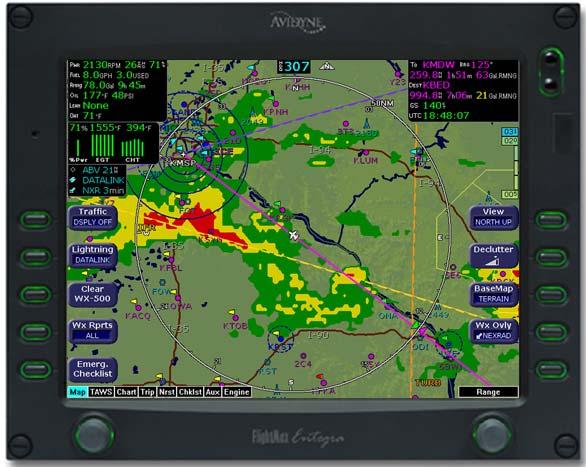
27 Map Page 2.2 Map Page Symbols Terrain and Position The EX5000 Map Page depicts your aircraft s position in relation to your flight plan, nearby airports, terrain, traffic, lightning, special use airspace and other navaids. Note: For details about the Map Symbols, see Section 13.7, "Map Symbols" on page Figure 2.2 Map Page Symbols Terrain and Position 1) Data Blocks (Left & Right) View navigation and engine (when equipped with engine monitor) data in data blocks in the upper corners of the display. For more information, see Section 10.4, "Data Block Edit Page" on page 82. 2) Heading/Track Indicator Three triangles around the compass rose provide actual track, desired track, and heading indications. The H/T Block provides digital readout of the current heading, or actual track. Map orientation is indicated in the triangle to the right of the H/T Block. Entegra EX Rev 07
28 Map Page Symbols Terrain and Position Table 2.1 Track Indicator Graphics Heading Track Map Orientation Heading Desired Track North Up Track Heading Heading Up Actual Track Track Up 3) Sensor Status Box Displays the status of the available sensors including radar, traffic, lightning and both 2-Way Datalink and Broadcast Datalink. The NEXRAD (NXR) display includes the NEXRAD data age, which is the elapsed time since the product was created by the weather provider. See Table 13.1 Sensor Status Block Symbols on page 112 for more information on status box symbols. (Optional Engine Instrument Sensor Status information is described in Table Engine Instrument Data Block Information on page 118).! When using Datalink weather, monitor the data age so you are aware of the time elapsed since the last weather update. 4) Compass Rose/Range Ring Displays a 360-degree or 120- degree compass circle or arc and indicates current range setting. The range number is the distance from the airplane symbol to the compass arc. Note: NEXRAD is the only Broadcast Datalink product on the EX5000 that displays the time since the product was created by the weather provider. Refer to the Trip page for information on all other weather products Rev Entegra EX5000
29 Map Page 5) Terrain Scale Shows highest and lowest limits of terrain in displayed area. Legend colors in between these numerics represent terrain elevations. Blue obstacle clearance number shows the top of the highest obstacle, when greater than the highest displayed terrain. Terrain data is not displayed when your aircraft s latitude is greater than 75 degrees (north or south).! The displayed terrain and obstacle indicators are only advisory. It is dangerous to rely on the EX5000 as the sole source of obstacle and terrain avoidance information. Always refer to current aeronautical charts for appropriate terrain and obstacle information. 6) METAR Flags For each reporting airport, when Datalink is installed and active, a METAR flag provides a quick overview of the weather for that station. The METAR flags are color-coded: 7) Interstate Highways Depicted as brown lines when terrain is selected to be shown. Interstates are labeled in white. (e.g. I-95). Highways are removed from the terrain map when the range is greater than 300NM. 8) Lightning Indications If configured with WX-500 or TWX-670 sensor, shows geographically referenced lightning strikes. Lightning strikes from onboard sensors display for three minutes. Lightning display depends on the selected mode, as follows: Datalink Mode If Broadcast Datalink is installed and you have an appropriate broadcast datalink service level, shows as color-coded lightning symbols. Datalink strikes darken in color until they are removed after 15 minutes. WX-500 or TWX-670 Strike Mode Entegra EX Rev 07
30 Map Page Symbols Terrain and Position WX-500 Cell Mode 9) Special Use Airspace The EX5000 uses several different line styles to convey special use and class airspaces. Class B is solid blue line, Class C is solid magenta line. Class D is dashed blue line, MOA, Warning, and Alert areas are solid yellow lines, and restricted and prohibited areas are solid red lines. See Table 13.7 Airspace and Airways Lines on page ) Storm Cells If storm cells are present, the EX5000 displays the cells along with the cell s groundspeed, in knots, and direction of travel, and it shows the cell echo tops with a label. If there is a greater than 50% chance of hail, the cell displays with a white background Rev Entegra EX5000

31 Map Page 2.3 Map Page Symbols Runways and Flight Plan When looking at the Map Page in short range, you can see details, such as runway diagrams, that are not available at longer ranges. Note that your flight plan is always shown Figure 2.3 Map Page Symbols Runways and Flight Plan 1) Ownship Symbol Shows the position of your aircraft in relation to the moving map and the selected view. 2) Airport Runway Diagrams Displays runway layouts of nearby airports when looking at the map at a less than 5NM range. As you range in, the scaled runway diagram with heading labels shows your exact location in proximity to the field. 3) Traffic Indications Shows traffic symbol relative to current position and includes relative altitude (when available) with respect to airplane symbol. See your traffic sensor User s Manual for further details. When available, TIS installations will show a ground track stinger for each intruder, indicating the intruder s track as measured by ground radar. Traffic Symbols are shown in Table 3.1 Traffic Symbols on page 22. Entegra EX Rev 07
32 Map Page Symbols Runways and Flight Plan 4) Flight Plan Displays the active flight plan from the GPS. The current leg displays in magenta and all remaining legs are shown in white. When you select an approach procedure on the Garmin 430, all approach segments including holds, DME arcs, procedure turns, etc., are shown (when connected via the ARINC 429 bus). Note: The Garmin 430W can use parallel track. If the parallel track is active, the current leg will be displayed in white. Note: For most GPS units, the EX5000 does not display the active course leg when you are adjusting the desired track in OBS mode. The desired track leg will display after you finish selecting the course and exit the OBS mode of the GPS. Note: The Garmin GNS 430/GNC 420 does not differentiate curved flight path segments from straight segments when interfaced with the EX5000 via an RS232 interface. Therefore, the EX5000 will connect the beginning and end waypoints of a curved segment, such as a DME arc, with a straight line. Under these circumstances, the straight line must be ignored. Approach procedures should be flown using the GNS 430/GNC 420 navigator s CDI as the primary reference. Consult your avionics installation facility to determine if your EX5000 is interfaced to the GNS 430/GNC420 via ARINC 429 or RS232. 5) Obstacles The EX5000 s database contains towers and other obstacles greater than 200 feet AGL. Obstacles can be displayed with MSL altitude label. Note: For example, a 2000 foot tall TV tower located in Denver (elevation 5300 feet MSL) will be depicted as being at 7300 feet MSL Rev Entegra EX5000
33 Map Page Table 2.2 Obstacle Graphics Graphic Meaning Height (AGL) Single Obstacle 200 AGL to < 1000 AGL Obstacles within 1NM of each other Single Obstacle Obstacles within 1NM of each other 200 AGL to < 1000 AGL 1000 AGL or higher 1000 AGL or higher 2.4 Map Orientation Control The Map View button allows you to control the orientation of the map and sensor data displayed on the EX5000. EX5000 traffic and lightning sensor symbols are positioned relative to the aircraft nose. When the Map View is North-Up you need to pay more attention to locate traffic outside the aircraft. Set Map View to Center or Forward to display this data consistent with typical dedicated traffic and lightning sensor displays. 2.5 Errors Displayed on the Map Page In general, the following errors are externally generated, but you may notice them on the Map or other pages on the EX Loss of GPS Input Loss of primary GPS is annunciated in a number of ways on your EX5000. The Nav Source not communicating message displays. The aircraft symbol is removed. There is no heading information displayed (if GPS is lost, no heading is displayed regardless of heading source). The desired track icon is removed from the compass rose. There is no groundspeed information displayed. The EX5000 continues to provide Datalink weather for your flight at its last known position. If the primary GPS fails during flight and you have a second GPS connected to the EX5000, you may switch your GPS input to the backup source by pressing the Nav Src button on the Aux Page. Entegra EX Rev 07
34 Errors Displayed on the Map Page Loss of Heading Input The source for heading data on your aircraft is dependent upon the particular complement of equipment you have installed in your aircraft. Loss of heading is typically associated with the failure of one of the following: The WX-500 Stormscope system (if installed and a heading source is connected to the WX-500). The Skywatch system (if installed and a heading source is connected to the TAS). A problem with heading from a Primary Flight Display (PFD). The GPS (This would be a pass through of the heading from another source, such as an Avidyne PFD. The GPS does not determine heading). If an installed heading source becomes unavailable or invalid, the EX5000 will automatically switch to using GPS track for map alignment. If the track source also becomes unavailable or invalid, the following conditions will occur: All traffic and lightning data is removed from the display. The aircraft symbol is replaced by a direction-less symbol (a white + symbol). The compass labels (N,S, E, and W) are removed from the display. The map and flight plan data will continue to be displayed. The map orientation annunciation is removed from the display The heading/track indicator will display a series of dashes ( --- ) The map is oriented True North Up. What to do: Have the avionics wiring inspected. When heading/track is restored, Map will resume normal operations Rev Entegra EX5000
35 3 Traffic Mode and the Traffic Page When a Traffic Advisory (TA) is reported from the traffic sensor, the EX5000 displays a traffic alert message in the Message Bar. Pressing the ACK button next to the message acknowledges the traffic alert and displays the dedicated traffic page that provides you maximum traffic situational awareness.! It is dangerous to rely on the EX5000 as your sole source of data for collision avoidance. Traffic information is provided as an aid to visually acquiring traffic. Maneuver your aircraft based only on ATC guidance or positive acquisition of conflicting traffic. It is your duty as pilot in command to see and avoid. Notes: The intruder track information provided by TIS traffic systems is only accurate to within 45 of true intruder track. Take this into account when visually acquiring the reported traffic. Keep in mind that intruder traffic can maneuver at any time, and the current intruder track direction does not guarantee the intruder will continue along that track. For traffic sensors without track information (e.g. TAS), traffic symbols are shown without the stinger. 3.1 The Dedicated Traffic Page The dedicated Traffic Page is a specially configured Map page with the following settings: View Center, with heading (or track) up Range 5 NM Base Map No terrain or political boundaries Declutter No symbol or airspace depictions Lightning Not displayed Flight Plan Displayed Datalink Weather Not displayed. Up to 5 non-bearing intruders (traffic threats reported by the traffic sensor without valid bearing) are listed below the airplane symbol. Entegra EX Rev 07

36 The Dedicated Traffic Page Acknowledging the TA message from the Traffic mode removes it from the message bar, allowing other messages to be displayed. The TA message is automatically removed when the threat is reduced or the intruder is no longer present. 1 Figure 3.1 Map Page Traffic Mode 1) Exit Traffic Restores the Map Page to the previous settings. If the Map Page is restored prior to acknowledging a TA, the message will remain displayed and acknowledging it will once again bring up the dedicated Traffic Page. Note: Traffic limitations and operational ranges depend on the installed traffic sensor. For TAS or TCAD sensors, see the corresponding sensor Pilot Guide. For TIS sensors, see Section of the Aeronautical Information Manual. The available Traffic button modes are listed below. For more information on specific traffic sensor modes, consult the user documentation for your traffic sensor. Avidyne TAS600 series (including 9900BX), Skywatch, and Bendix/King Traffic modes are ABOVE, NORMAL, UNLIMTD, BELOW, and DSPLY OFF Rev Entegra EX5000
37 Traffic Mode and the Traffic Page TCAD 9900B Traffic modes are GROUND, TERMINAL, STANDARD, ENROUTE, UNLIMITED, APPROACH, and DSPLY OFF. Note that some TCAD installations will support automatic mode switching by the TCAD unit. The current mode is always reported on the EX5000 screen. TIS Traffic modes are DSPLY ON and DSPLY OFF. Entegra EX Rev 07
38 Traffic Symbols 3.2 Traffic Symbols On the EX5000, aircraft traffic detected by a Traffic Sensor (referred to as intruders) are displayed as one of three symbols. If a compatible TIS system is installed and intruder track information is available, the appropriate symbol will be shown with a stinger which depicts the current ground track of the intruder, as detected by ATC radar systems. The traffic symbols are: Table 3.1 Non-TIS Symbol Traffic Symbols TIS Symbol Type Meaning Traffic Alert (TA) Traffic within the alert zone defined by the traffic sensor. Proximate Traffic Traffic close to your position but not within an alert zone. Other Traffic Traffic detected by the traffic sensor, but determined not to be a current threat.! Traffic sensors do not provide any traffic awareness data for aircraft without operating transponders. Therefore, these aircraft will not display on the EX5000. It is your responsibility to see and avoid all other traffic and to maintain appropriate separation. Traffic alert information is displayed in the message bar as in the example above. 1) Relative bearing of target. 2) Range in nautical miles ) Relative altitude of traffic to your current aircraft altitude. For example, -200 would be 200 feet below your aircraft, as reported by the traffic sensor Rev Entegra EX5000
39 Traffic Mode and the Traffic Page Intruders are displayed as they are received from and identified by the sensor. The threat level assigned to an intruder is specified by the sensor when it transmits the intruder data. Threat data, range, bearing, altitude, ID and closing direction are defined by the sensor and the type of system. If the intruder altitude and vertical speed are known, they are displayed alongside the intruder symbol. The number immediately above or below the traffic symbol indicates the relative altitude of the intruder to your position, in hundreds of feet. An arrow next to an intruder symbol shows the direction of any vertical movement of the intruder that is in excess of 400 feet per minute. For example, in the Traffic Alert example shown in Table 3.1, the intruder is 500 feet below and is climbing. In addition, the TIS example shows the intruder is moving along a track approximately 45 degrees to the right of our current map alignment. (i.e. if the EX5000 map is set for North Up, the intruder is flying a track somewhere between 023 and 067. This is the accuracy limit of the intruder track data.) 3.3 TIS Sensor Status The TIS interface is only available on the EX5000. For TIS installations, the following may be reported in the Traffic status block on the EX5000 Map Page: OPER The TIS sensor is operating normally. CST 00:00 The TIS sensor has temporarily lost the information feed from ground-based radar and is in coast mode. The EX5000 will continue to display the traffic last received, while the CST timer will count the seconds since the last valid data. RMV 00:00 After 12 seconds of coasting, the TIS sensor will remove the traffic display and display RMV, and continue to count the time since the last valid data. UNAVAIL More than 60 seconds have passed since valid data was received, or TIS data is not available at the current aircraft location. SBY The TIS sensor is in standby mode. DATA FAIL The TIS sensor has reported an internal fault. Traffic information will be removed from display. Entegra EX Rev 07

40 4 TAWS Page (Optional) If your EX5000 system has been configured with a Terrain Awareness and Warning System (TAWS), turn the Page knob to TAWS to view the TAWS Page.!! 4.1 TAWS Information Any display of yellow or red on the TAWS page indicates an imminent terrain or obstacle hazard. The TAWS display on the EX5000 is an optional component of any TAWS-B installation, and is intended only to enhance situational awareness. All terrain avoidance maneuvering must be predicated on indications from the installed TAWS system, and not from the EX Figure 4.1 TAWS Information 9 Entegra EX Rev 07
41 TAWS Page (Optional) 1) Range Annunciation The range number indicates the currently selected range as selected by the Range knob. The supported ranges are 2.5, 5, 10, 20, 40, 80, 160, 240, and 320 nm. At start up, the EX5000 TAWS range defaults to 80nm. 2) Display Orientation This annunciation describes the orientation of the TAWS display. If heading is available to the EGPWS, the TAWS display orientation is heading up, with the aircraft's heading to the top of the display. HDG ### MAG displays, where ### is the aircraft's magnetic heading as reported by the EGPWS. If Heading is lost or not available to the EGPWS, the EGPWS may use magnetic ground track instead, and TRK ### MAG displays, where ### is the aircraft's magnetic ground track. In certain locales, such as near the magnetic poles, magnetic variation may become unreliable. The Display Orientation will switch to the true value, for example, HDG ### TRU or TRK ### TRU. If neither heading nor ground track is available, the terrain will be replaced by the cyan message TAWS Display Unavailable. 3) Scan Marker The marker is a short white line that moves across the top of the display area. It indicates the current position of the scan. 4) Peaks Mode Elevations Appears only when your EGPWS has been installed with the Peaks Mode option selected. The two numerical values correspond to the highest terrain/obstacle elevation displayed and the bottom elevation of the lowest color band displayed. Elevations are expressed in feet above sea level, with the hundreds digit displayed half size, i.e. 108 is equal to 10,800 feet and 010 is equal to 1,000 feet. If there is no appreciable difference in elevation (flat terrain) only the highest value displays. The color of each elevation value is the same as the color of the terrain display containing that elevation (green, yellow, or red). During a terrain alert, threatening terrain will be displayed as bright red and/or bright yellow. The elevation value colors are not modified in this case, but continue to correspond to the colors that would appear in the TAWS display under normal circumstances, and represent the actual elevation of the terrain relative to the aircraft. Entegra EX Rev 07
42 TAWS Information 5) Range Rings Range rings are shown as solid white lines. The distance to the outer ring is shown in the Range annunciation. The inner ring is one half the range of the outer ring. 6) Terrain Data Terrain data is depicted as color areas representing various elevations relative to your aircraft and potential hazard situations. 7) Azimuth Lines When pressed, labeled azimuth lines appear every 20 degrees. Press it again to remove the azimuth lines. 8) Geometric Altitude Presents current geometric altitude as calculated by the EGPWS. The geometric altitude is calculated via GPS altitude reporting. 9) Range Knob Changes the TAWS display range. During the short delay between the request for a new range (by turning the range knob) and the actual display of data at the new range, a Requested Range Annunciation displays. This is a dashed box immediately below the Range Annunciation, containing the new range that has been requested. If too many TAWS range requests are made before the EGPWS completes a full scan, the display may temporarily say TAWS Failed, but will resume normal operation within a few seconds. Note: The EX5000 displays TAWS data that is received from the TAWS sensor. The EX5000 does not generate its own TAWS data.! MSL-G is based on an internally calculated geometric altitude by the TAWS. Geometric altitude is the height above MSL derived from GPS. It represents the aircraft's calculated height above MSL and serves as the reference altitude for color-coding of the TAWS terrain display and as the input to the TAWS look-ahead algorithm. Because it is derived from GPS altitude, this reference altitude will often differ from corrected barometric altitude. The geometric altitude, which may be in error by 100 feet or more, is not to be used for navigation. It is presented to provide the crew with additional situational awareness of true height above sea level upon which TAWS terrain alerting and display is based Rev Entegra EX5000
43 TAWS Page (Optional) 4.2 TAWS Operation Terrain and obstacle alerts are the most critical situations displayed by TAWS. There are two levels of alerts: Caution Possible terrain or obstacle conflict within seconds. Warning Possible terrain or obstacle conflict within 30 seconds. Note: At the maximum range settings of 240nm and 320nm, terrain data for portions of the display beyond 320 nm may not be available. At these range settings, portions of the display representing distances greater than 320 nm may be black even though significant terrain may be present. The occasional loss of this display data occurs at the extreme limits of the EGPWS, but does not compromise safety or terrain awareness. When a caution alert is triggered, the terrain or obstacle that caused the alert displays in bright yellow, as shown below. In addition, a message describing the nature of the alert is presented in the message bar. Figure 4.2 Terrain Caution Condition Entegra EX Rev 07

44 TAWS Operation When a warning alert is triggered, the terrain or obstacle that caused the alert displays in bright red. In addition, a message describing the nature of the alert is presented in the message bar. Figure 4.3 Terrain Warning Condition When a caution or warning alert is active, the display image surrounding the target is enlarged somewhat to allow the terrain or obstacle to be better seen on the display. See Table TAWS Messages on page 119 for a complete listing of TAWS messages. If a terrain or obstacle alert occurs while a page other than TAWS Display is being displayed, a terrain or obstacle alert message displays in the Message Bar. When you acknowledge this message, the EX5000 automatically switches to the TAWS Display Page. The message bar is removed from the display when the EGPWS is no longer in alert status, or if you acknowledge the message from the TAWS Page Rev Entegra EX5000
45 TAWS Page (Optional) 4.3 TAWS Reference Auto-Range If the EGPWS has been installed with the auto range option selected, the terrain display range is automatically set to 10nm whenever a terrain or obstacle alert takes place, overriding the current range selection. To remind you that the range has been automatically changed, the text Auto is added in the range annunciation. Manual range control is not disabled by auto-range. You can reset the range to any desired value Simultaneous Alerts If a terrain or obstacle alert and Traffic Advisory (TA) are issued at the same time, TAWS will have priority, and the terrain or obstacle alert message will be presented in the Message Bar. When you acknowledges the alert, the EX5000 switches to the TAWS Display Page. After you acknowledge the TAWS message from the TAWS Page, the TA is shown in the Message Bar. If you then acknowledge the TA, the dedicated Traffic Page, discussed in Section 3.1, "The Dedicated Traffic Page" on page 19, will pop up. If a TA occurs while a terrain or obstacle alert is in progress and the TAWS Display Page is being displayed, the EX5000 will remain in TAWS Display and the TA message will appear in the Message Bar. Acknowledging the TA message displays the dedicated Traffic Page Terrain Messages and Error Indications The TAWS display may present messages in the Message Bar. Press the ACK button to acknowledge TAWS Page messages and remove them from the message bar. Large text annunciations will remain. See Table TAWS Messages on page 119 for a listing of possible TAWS messages. If the TAWS Page is accessed immediately after you turn on the EGPWS, the system may still be initializing and the TAWS Page will display the text TAWS Initializing rather than the expected terrain. The EGPWS and TAWS Page will begin normal operation when initialization is complete. Entegra EX Rev 07
46 TAWS Reference Table 4.1 Color Solid Red Solid Yellow 50% Red Dots 50% Yellow Dots 25% Yellow Dots Solid Green 50% Green Dots 50% Green Dots 16% Green Dots 16% Green Dots Black EGPWS Display Color Formats Meaning Terrain/Obstacle threat area, a warning is generated. Terrain/Obstacle threat area, a caution is generated. Terrain/Obstacle that is more than 2,000 feet above aircraft. Terrain/Obstacle that is between 1,000 and 2,000 feet above aircraft. Terrain/Obstacle that is 500 (250 with gear down) feet below to 1,000 feet above aircraft altitude. Peaks mode only. Shown only when no Red or Yellow Terrain/ Obstacle areas are within range on the display. Highest Terrain/Obstacle not within 500 (250 with gear down) feet of aircraft altitude. Terrain/Obstacle that is 500 (250 with gear down) feet below to 1,000 feet below aircraft altitude. Peaks mode only. Terrain/Obstacle that is the middle elevation band when there is no Red or Yellow terrain areas within range on the display. Terrain/Obstacle that is 1,000 to 2,000 feet below aircraft altitude. Peaks mode only. Terrain/Obstacle that is the lower elevation band when there is no Red or Yellow terrain areas within range on the display. No significant terrain/obstacle. 16% Blue Peaks mode only. Water at sea level elevation (0 feet MSL). Magenta Dots Unknown terrain. No terrain data in the data base for the magenta area shown Rev Entegra EX5000

47 5 Trip Page The Trip Page is continuously updated during flight. The distance and the time values are updated with each new positive fix from the GPS. The route legs advance with each waypoint message. Turn the Page knob to bring up the Trip Page, which shows the remaining legs in the current flight plan and other data being received by the EX5000 from the GPS. If the entire flight plan does not fit on the screen, an ellipsis (...) displays in the next to last line. The destination line is always displayed. All flight plans are from the GPS. A No Flightplan Available message displays if there is no flight plan entered or if the GPS has failed. 5.1 Trip Page Information Figure 5.1 Trip Page Information 1) Current ground speed and track As reported by your GPS Navigator. Entegra EX Rev 07
48 Trip Page Information 2) Course Deviation Indicator (CDI) Shows lateral distance (Crosstrack deviation) from desired course, providing continuous navigation reference when viewing the Trip Page. 3) Time Local and UTC time in HH:MM:SS using a 24-hour clock format. 4) Flight Plan Waypoints Flight Plan information from your GPS. Active waypoint is shown in magenta. For Flight Plan waypoints, the following data displays: WPT Waypoint identifier as received from the GPS. BRG Bearing to current waypoint. DTK Desired track to waypoint. NM Cumulative great circle distance of each flight plan leg. ETE Cumulative estimated time enroute to waypoint in H:MM format for each flight plan leg at current ground speed. ETA Estimated time of arrival to waypoint in HH:MM formatted for local time. Fuel (Gals) Available with Engine and Fuel Monitor function. Displays remaining fuel at each waypoint. Note: For the Garmin 430W, if the parallel track is active, the above data, WPT, BRFDG, DTK, NM, ETE, ETA and Fuel (Gals) are not displayed. Chart Icon Indicates that an Instrument Procedure chart is available for the associated airport. An I on the icon indicates that at least one ILS approach chart is available for the associated airport, on the CMax Chart page. Chart icons only display for those airports for which you have JeppView subscription coverage. For more information, see Section 8.1, "About CMax" on page 48. Intermediate waypoints are shown with the prefix Wx:. The Trip Page includes distance (NM), waypoint name, and METAR, if available Rev Entegra EX5000

49 Trip Page Intermediate waypoints are determined by your current flight plan. The EX5000 adds intermediate waypoints along your flight path to provide weather information between flight plan waypoints for longer flight plan legs. This can provide you with a fuller picture of enroute conditions. 5) METAR Symbol A METAR report is shown for each flightplan waypoint that uses the same METAR condition symbols as described in Section 2.2, "Map Page Symbols Terrain and Position" on page 11. 6) Trip Display Area Displays the information that you select with the Display button for the selected waypoint, when available. 7) Destination Airport Info Provides quick access to airport information for the destination airport, when available. 8) Display Controls the display shown in the lower portion of the screen. The selections are: METAR Displays the decoded text METAR for the selected waypoint, when available. If METAR cannot be decoded, raw text METAR will be displayed. Legend If Broadcast Datalink is installed, shows the types of data used in graphical METAR and NEXRAD displays. Broadcast Status If Broadcast Datalink is installed and available, displays satellite, signal and serial number information for the Broadcast Datalink system. Also displays the elapsed time since reception of the various types of weather data. If the time since reception for any particular weather product is greater than the limits defined by the system, a cyan alert message will display in the message box Entegra EX Rev 07

50 Trip Page Information on the Aux Main Page and in the message bar. For example, if 91 minutes has elapsed since the last TAF data was received, a "Broadcast TAFs > 90 min" message will display in the message bar and in the message list on the Aux page. When these messages are displayed, all data for that product is removed from the MFD. The Trip page will indicate that new data for that product has not been received for greater than X minutes, where X is the time limit defined for each product (typically 90 minutes). Note: Broadcast Datalink times indicated on the Trip page display the time since the product was received by the MFD ( time since reception ). Therre is an inherent time delay between the creation and reception of the broadcast weather data. Winds Aloft and Freezing Level/Temperatures Aloft Depending on your WSI or XM WX service level, displays Winds Aloft and Freezing Level (XM) or Temps Aloft (WSI) data from Broadcast Datalink, if available. The Winds Aloft direction is measured from true (not magnetic) North. Winds are interpolated for each Trip Page waypoint and are based on a computer forecast model that is updated hourly. The XM Freezing Level forecast (see figure) displays the expected altitude of the freezing level for the waypoint, while the WSI Temperatures Aloft forecast provides temperature data for each winds aloft flight level Rev Entegra EX5000

 Chart If CMax approach charts are installed and available, provides a quick jump to the Chart Page with the highlighted airport")
51 Trip Page TAFs The EX5000 provides text Terminal Aerodrome Forecasts (TAF) from the National Weather Service via Broadcast Datalink, if available. TAFs are not decoded. Note: Winds Aloft and TAFs are only available with certain broadcast packages. See the broadcast datalink documentation for more information. 9) Chart If CMax approach charts are installed and available, provides a quick jump to the Chart Page with the highlighted airport pre-selected. For information about CMax, see Chapter 8 "CMax Chart Pages (Optional). Entegra EX Rev 07
52 Trip Page Information 10) Select Knob Use the right knob to move the cursor over the desired waypoint in the flight plan, which selects the plain-text METAR to be displayed along the bottom half of the screen.! Garmin GNS400/500-series users: When the EX5000 is interfaced to a Garmin GNS400/500-series GPS via RS-232, the GPS may send duplicate waypoints while in approach mode. These duplicate waypoints may affect the distance and time readings on the Trip Page. Use the GPS as the primary source of navigation information for approach procedures. Consult your avionics installation facility to determine if your EX5000 is interfaced to the Garmin GNS-430 via ARINC 429 or RS Rev Entegra EX5000
53 6 Nearest Page (NRST) The Nearest Page displays the nearest airports within 100NM of your present position or the nearest airports to your destination. Through the buttons, you can access detailed information about each airport. The buttons also allow you to view the nearest VORs, NDBs, Intersections, and Obstacles. 6.1 Nearest Page Figure 6.1 Nearest Page 7 1) Airport details By default, displays the following details about the airports nearest to your current location: METAR and Chart Symbols Waypoints with METAR reporting stations display a color-coded METAR flag when Datalink is active. If CMax approach charts are installed, a chart icon displays next to any METAR reporting station for which an Instrument Procedure chart is available. An I on the icon indicates that at least one ILS approach chart is available. See Chart, below, for more information. ID Airport identifier of the airport. Entegra EX Rev 07
54 Nearest Page BRG Bearing to the airport. NM Distance to the airport. Freq Radio frequency to contact this airport. Name Airport common name. 2) METAR Conditions Displays the decoded text METAR for the selected airport when Broadcast Datalink is enabled and a METAR is available. 3) Airport Info Provides quick access to airport information for the airport highlighted. Airport Info only appears when viewing the Airports Nearest to Position and Airports Nearest to Destination. Airport Info displays a page similar to Figure ) TYPE Cycles through the various Nearest data types in the following order: PPOS APT (Airports Nearest Present Position) Graphical METARs, airport identifier, bearing, distance from the aircraft present position, frequency, and airport name. DEST APT (Airports Nearest Destination) Graphical METARs, airport identifier, bearing, distance from the destination airport, frequency, and airport name. VORs Identifier, bearing, distance, frequency, and name. NDBs Identifier, bearing, distance, frequency, and name. Intersections Identifier, bearing, and distance. Obstacles MSL (and AGL) height, bearing, and distance. 5) FILTER Press to see all airport types (SHOW ALL) or only the airport types as defined on the Airport Filter Page (ON) (see Section Figure 10.2, "Airport Filter Setup Page" on page 78). Filter is only visible on the Nearest Airport Pages. 6) Chart If CMax charts are installed and you select an airport that has a chart icon, the Chart button appears, which provides a quick jump to the selected approach charts. For information about CMax, see Chapter 8 "CMax Chart Pages (Optional). 7) Select Knob Use the right knob to move the cursor up or down to highlight a specific airport or other data type Rev Entegra EX5000
 Back to Nearest Returns to the Nearest Page.")
55 Nearest Page (NRST) 6.2 Airport Info Page When you press Airport Info from the Nearest Page, the Airport Information Page displays for the selected Airport, as shown: 1 2 Figure 6.2 Airport Information Page 2 1) Back to Nearest Returns to the Nearest Page. 2) Step and Jump Knobs If the communications frequencies list is long enough so that it does not fit on a single page, the Step and Jump labels appear on the left and right knobs: Step Scrolls the page one line. Jump Scrolls an entire page (or to the end of the list). Entegra EX Rev 07
56 7 Checklists Checklists provide step-by-step instructions to help you perform common, and uncommon, tasks relating to your aircraft. There are two ways to access the Checklists: For normal Checklists, turn the Page Knob to Chklist. As described in Section 7.2, "Normal Checklists" on page 41, the left-hand buttons display the types of available checklists. For Emergency Checklists, press the Emerg. Chklist button available on every EX5000 Page. This will take you directly to the Emergency Checklist section, described in Section 7.4, "Emergency Checklists" on page 44. This section discusses the following topics: Checklist Versions, page 40 Normal Checklists, page 41 Checklist Buttons and Knobs, page 43 Emergency Checklists, page 44 Performance Checklists, page Checklist Versions The EX5000 startup screen and the Aux Main Page display the currently loaded checklist version. While the checklist version reflects the current MFD software part number, checklists may be updated by Columbia in the future. Entegra EX Rev 07
 Checklist Types Provides access to the top-level Normal checklists by phase of flight:")
57 Checklists 7.2 Normal Checklists Figure 7.1 Normal Procedure Checklist 1) Checklist Types Provides access to the top-level Normal checklists by phase of flight: Before Takeoff In Flight and Landing Entegra EX Rev 07
58 Normal Checklists Figure 7.2 Normal Checklists 2) Available Checklists Menu Lists the checklists within each type. Press Show Checklist to view the highlighted checklist. Normal Checklists will automatically sequence in order as checked off. 3) Perf. Data Displays the list of Performance Data Checklists, described in Section 7.5, "Performance Checklists" on page 47. 4) Emerg. Checklist Displays the list of Emergency Checklists, described in Section 7.4, "Emergency Checklists" on page 44. 5) Show Checklist Press Show Checklist to view the highlighted checklist. 6) Selection Control Use right knob to move the blue outlined box up or down to highlight a specific checklist within each menu for viewing Rev Entegra EX5000
 Next Checklist When the current checklist is completed, indicated by all steps appearing green and checked off, press Next Checklist to view the next checklist in")
59 Checklists 7.3 Checklist Buttons and Knobs Figure 7.3 Example Normal Checklist 4 1) Next Checklist When the current checklist is completed, indicated by all steps appearing green and checked off, press Next Checklist to view the next checklist in sequence. 2) Done/Undo Press Done to change the current checklist item to green, place a checkmark to the right of it, and automatically step down to the next checklist item. If an already-acknowledged checklist item is highlighted, the Done button will be relabeled Undo allowing the item to be reverted to the undone state. 3) Back Returns you to the menu of checklists in each type. 4) Selection Control Once inside a Checklist, use the right knob to move up and down the checklist. The current step in the checklist is highlighted in magenta and has an arrow pointing to it from the right side. Entegra EX Rev 07

60 Emergency Checklists 7.4 Emergency Checklists The EX5000 includes complete Emergency checklists. To access the Emergency checklists, press the Emerg. Checklist button in the lower left corner Figure 7.4 Emergency Checklists 5 1) Checklist Types Provides access to the top-level Emergency checklists for each phase of flight including: Ground Emergency In-Flight Emergency Landing Emergency System Malfunctions 2) Normal Checklist Press Normal Checklist to return to the selection of normal operating checklists Rev Entegra EX5000
61 Checklists 3) Available Checklists Menu of checklists within each type. Push Show Checklist to display the desired list. 4) Show Checklist Press Show Checklist to view the highlighted checklist. Entegra EX Rev 07


62 Emergency Checklists 5) Selection Control Use right knob to move the blue outlined box up or down to highlight a specific checklist within each menu for viewing Rev Entegra EX5000


63 Checklists 7.5 Performance Checklists The Performance Data tables and charts are accessible from the Normal Procedures page. All data is derived directly from the aircraft POH. The available charts are: Airspeeds for Normal Operation Wind Components Takeoff Distances Cruise Performance Landing Distances In all airspeed and performance tables, the POH contains the most complete data available. Entegra EX Rev 07
64 8 CMax Chart Pages (Optional) CMax is an optional Avidyne feature that allows you to view Jeppesen Terminal charts on your EX5000. If CMax is installed on your aircraft, you can select Charts from the Page Bar to view the CMax charts. This section discusses the following topics: About CMax, page 48 About Geo-Referenced Charts, page 49 CMax Chart Page, page 49 CMax Views, page 53 CMax Selection Page, page 57! As pilot in command, it is your duty to have alternate sources of approach data available to you. Do not rely upon CMax charts as your sole source of navigation information.! It is critical that you update the Jeppesen database regularly and prior to conducting flight operations to insure accurate data. Use of an outdated database is entirely at your own risk. 8.1 About CMax CMax charts include instrument approach procedures, arrivals, departures, airport diagrams, and various taxiway and airspace diagrams typical of Jeppesen printed charts. The CMax feature requires that you have a valid chart data subscription from Jeppesen Sanderson, Inc. For information on obtaining a CMax subscription, see the Avidyne Data Update Guide or the Jeppesen website at The Data Update Guide also contains instructions for loading the chart data to your Zip Drive or USB Flash Memory Drive. See Section Entegra EX Rev 07
65 CMax Chart Pages (Optional) , "Loading CMax Chart Data" on page 103 for information about loading CMax Data onto your EX5000. Note: You can load new CMax Chart data into the MFD as soon as you receive each data cycle. Any charts that have changes that are effective on a certain date are controlled within the data. The MFD will display the proper Chart data based on the current date and the effective date of the changes to the chart. 8.2 About Geo-Referenced Charts The greatest additions to situational awareness come from charts that are geo-referenced. A chart is geo-referenced when the chart data supports a correlation of chart position to actual latitude and longitude coordinates. This allows an ownship symbol and flight plan legs to be accurately represented on the chart. If a chart is not geo-referenced, the ownship and flight plan legs cannot be drawn on the chart. Most Jeppesen approach charts and airport diagrams are geo-referenced; most arrival, departure, and miscellaneous charts are not. 8.3 CMax Chart Page If CMax is enabled on your EX5000, you can access the CMax Charts Page by turning the Select knob to Chart. The Chart Page can have two charts ready for viewing at any one time: an airport diagram, and a procedure chart (or another miscellaneous chart associated with that airport). The airport and associated charts are selected on the Chart Selection Page, described in Section 8.5, "CMax Selection Page" on page 57. The EX5000 Startup Page reports the valid dates for the currently loaded chart data. If the date for the next update has passed, the Startup Page will report this in yellow cautionary text. If the chart data becomes more than 10 weeks out of date, access to the charts shall be revoked until new chart data is loaded. On power up, if your EX5000 is receiving a valid position from your GPS unit, the Chart Page will default to display the airport diagram of your current position. An approach procedure chart will not be displayed until one is selected. If no valid GPS position is available at start-up, the Chart Page will default to the Chart Selection Page for manual selection of a chart. Entegra EX Rev 07

66 CMax Chart Page If you select the Chart Page immediately upon power up, CMax may still be initializing and will display the following message: CMax Initializing/Please Wait. The Chart Page will begin normal operation when initialization completes. On landing, if the Chart Page is being displayed, the EX5000 will automatically switch to display the Airport diagram for the current location when the GPS Ground Speed drops below 50 knots. The Chart Page shows the airport diagram of the current airport, with ownship symbol for current aircraft position, if the airport diagram is geo-referenced Figure 8.1 CMax Chart Page (Airport) 12 1) Airport Identifier The airport identifier for the current airport displays in green. 2) Chart Name The name of the current chart being displayed, also in green. 3) Geo-referenced Symbol When the displayed chart is georeferenced, a small globe displays. If the chart is not georeferenced, the globe symbol is crossed out Rev Entegra EX5000
67 CMax Chart Pages (Optional) 4) Flight Plan Symbol an FPL symbol indicates the option to display the current flight plan is turned on. If the display of flight plan is turned off, the FPL symbol is crossed out. Note that if a chart is not geo-referenced or no flight plan is received from the GPS, the flight plan cannot be displayed even if the option is selected. 5) Select Chart Displays the Selection Page to allow you to select a new chart for display. For more information, see Section 8.5, "CMax Selection Page" on page 57. 6) Display Display allows you to toggle between displaying Airport and Procedure charts. Display Airport shows when the current Procedure chart displays. Press Display Airport to display the Airport chart. Display Procedure shows when the current Airport chart displays. Press Display Procedure to display the Procedure chart. 7) View Controls which portion of the chart is being displayed. See details below. 8) Remove Labels Removes the button labels from the page to allow a full view of the current chart. Press any button to redisplay the labels. 9) Emerg. Checklist Displays the list of Emergency Checklists. See Section 7.4, "Emergency Checklists" on page ) Ownship Displays the current position of the aircraft. The chart nominally remains fixed and the ownship symbol moves across the chart with aircraft movement. 11) Pan Buttons The right-hand buttons allow you to manually move the chart on the screen. The pan buttons are only active when the current view can be panned. The Plan view of each chart can generally be panned; many information pages, such as header and departure views, cannot. Not shown: Center When you use Pan, the Center button is displayed to allow you to re-center the chart. When panning, the aircraft position, and ownship symbol, may move towards or off the edges of the chart area. Press Center to re-center the chart on the current position hide the Center button. Entegra EX Rev 07

68 CMax Chart Page 12) Zoom Control Knob The right knob allows you to zoom the chart for close-up examination of a specific area. The label only appears when the current view can be zoomed. Most information view pages, such as headers, cannot be zoomed. If you have panned the chart, zooming all the way out to the full-screen chart size also re-centers the chart on the screen. A typical approach procedure chart is shown in Figure 8.2: 1 2 Figure 8.2 CMax Chart Page (Procedure) 1) Flight Plan The flight plan is overlaid on the Plan View when you select the flight plan display option (on Selection Page) and the chart is geo-referenced. If a flight plan does not display, check that you selected the correct airport and approach. 2) Flight Plan Active Leg The active leg of the current flight plan, if displayed, is magenta. Non-active legs are shown in green. Note: The Garmin 430W can use parallel track. If the parallel track is active, the current leg will be displayed in white Rev Entegra EX5000
69 CMax Chart Pages (Optional) Note: The ownship symbol on the Chart page is always oriented according to the current GPS ground track. Therefore, the ownship is always pointed in the direction the aircraft is moving, and does not show any crab angle induced by crosswind components. Note: For a flight plan to be displayed on a given chart there must be a waypoint on that chart in the flight plan. For example, a direct flight plan from KBED to KLAX passes over KEMT. If you bring up KEMT charts, the KBED-KLAX flight plan will not display. To display the flight plan over KEMT, a waypoint on an approach for KEMT must be included in the flight plan. 8.4 CMax Views The EX5000 provides two sets of charts, Procedure and Airport. For ease of use and readability, each chart is divided into sections that are shown individually. Use the Display button to toggle between Procedure charts and Airport charts. Press View to cycle through the available views for that chart. Note: If CMax detects non-standard data for a particular chart, a full chart view will be the only available view for that chart, and the georeferenced ownship and flight plan will be not be displayed Procedure Chart Views For the Procedure chart, the Header, Profile, and Minimums views also feature a small preview pane of the Plan View, which, although too small to read all chart details, gives the user a general overview of the approach for situational awareness. The flight plan and ownship symbol are also displayed on the preview pane. Entegra EX Rev 07


70 CMax Views The available views are: Table 8.1 Airport Procedure Views # View Description 1 of 4 Plan Includes a flight plan overlay if available (shown in Figure 8.2). 2 of 4 Header Contains general chart information and appropriate communication frequencies. 3 of 4 Profile Includes the profile view of the approach procedure. 4 of 4 Minimums Shows the descent minimums for the approach. Header View Profile View Minimums View Figure 8.3 Procedure Chart views Rev Entegra EX5000

.")

71 CMax Chart Pages (Optional) Airport Chart Views For airport charts, the available views are as follows: Table 8.2 Airport Chart Views # Chart Description 1 of 4 Plan Includes a flight plan overlay, if available (shown in Figure 8.1). 2 of 4 Header Includes general chart information and communications frequencies. 3 of 4 Runways Shows runway information for the airport. 4 of 4 Departure Displays specific departure procedure information. Header View Runways View Departure View Figure 8.4 Airport Chart Views Entegra EX Rev 07

72 CMax Views Note that not all charts will have all information sections. Airport charts, for example, may or may not have runway or departure information. For larger airports, this information is often large enough to warrant a separate chart, which can be selected from list on the Selection Page. Charts that cannot be split into smaller sections are shown as a complete chart, with the View button not displayed, since only one View type is available. Figure 8.5 Airport Departure Chart (Night View) Rev Entegra EX5000
73 CMax Chart Pages (Optional) 8.5 CMax Selection Page Figure 8.6 CMax Selection Page 1) Chart Selection list A list of all charts available for the identified airport. Although the majority of charts listed are indeed instrument approach procedure charts and are generally referred to in this documentation as procedures, the list also includes other types of charts such as airspace diagrams, taxi diagrams, special instructions, and other miscellaneous charts. Note: The EX5000 shows only those charts covered by your Chart data subscription. The Charts are listed in the Jeppesen chart index order. 2) Chart NOTAMs The Chart NOTAMs button only displays if chart NOTAMs exist for the currently-selected airport. Press Chart NOTAMS to bring up a window that lists any associated chart NOTAMs for the airport currently entered in the Airport Entry Field. See Section 8.5.2, "Chart NOTAMs Page" on page 61 for more information. Entegra EX Rev 07
74 CMax Selection Page 3) Day/Night Toggles the chart display between Day and Night modes. Day mode displays black text on a white background; Night mode is white text on a black background. Other colors such as water or shaded terrain are also adjusted for Day or Night mode. The EX5000 starts in Night mode to preserve night vision. 4) Flight Plan Toggles the display of the flight plan overlay on the chart Plan View between DISPLAY and DSPLY OFF. Changes to this selection are effective immediately. 5) Back to Active Returns to the current active chart display screen. Any inputs to the Airport Entry Field or Chart list are abandoned. Changes to flight plan display status, however, are preserved. 6) Change Airport Moves the cursor to the Airport Entry field, described in Section 8.5.1, "Selecting an Airport" on page 59. 7) Display Chart Loads the selected chart and displays it on the Chart Page. Remember that the associated Airport diagram is also automatically made available on the Chart Page when a procedure chart is loaded by pressing Display Chart. Note: As a valid chart, the Airport diagram is listed in the Chart Selection list, however, it is not usually necessary to load the Airport chart, since it is always accessible on the Chart Page by pressing the Display Airport button Rev Entegra EX5000
 Airport Entry Field This field accepts airport identification codes (such as KCAD, etc.). The EX5000 will try to autocomplete an airport entry as the first characters are entered.")
75 CMax Chart Pages (Optional) Selecting an Airport Use the Airport Entry Field to specify the airport you want to view Figure 8.7 Airport Selection Page 5 1) Airport Entry Field This field accepts airport identification codes (such as KCAD, etc.). The EX5000 will try to autocomplete an airport entry as the first characters are entered. Press the AutoFill button to immediately fill this field with the destination airport. Only those airports within the coverage area are auto-completed. A list of all charts available for the identified airport appears in the chart list area. The name of the airport in the Airport Entry Field is listed next to the entry field. Entegra EX Rev 07
76 CMax Selection Page 2) AutoFill When pressed, moves the detected destination airport listed on the button into the Airport Entry Field. Note: The AutoFill button automatically detects the destination airport if the final waypoint is an airport or a waypoint that is part of an instrument approach procedure. However, for some approaches, AutoFill may detect another nearby airport rather than the intended destination. Make sure the desired airport is displayed before pressing the button. AutoFill does not display under the following conditions: An Airport cannot be determined due to GPS limitations. When the feature is not supported by some GPS models. The current airport destination is not available in your chart data coverage area. 3) Select Chart Moves the active selection cursor from the Airport Entry Field to the Chart Selection list. 4) Next Letter Use Next Letter to move the cursor within the Airport Entry Field to the next character location. 5) Select Knob Use the right knob to select the character for the current cursor position when entering an airport identifier Rev Entegra EX5000
 Close Press Close to close the Chart NOTAMs window and return to the Selection Page.")
77 CMax Chart Pages (Optional) Chart NOTAMs Page Displays the chart NOTAMs associated with the currently displayed airport. 1 Figure 8.8 Chart NOTAMs Page 1) Close Press Close to close the Chart NOTAMs window and return to the Selection Page. Press the Chart NOTAMs button from the Selection Page to display the chart NOTAMs associated with that airport. Chart NOTAMs specific to that airport are listed first, followed by any general chart NOTAMs. Note: Chart NOTAMs address changes to information contained on the charts, and do not include local or regional operational NOTAMs. Always obtain local and regional NOTAMS before any flight. Entegra EX Rev 07
78 CMax Selection Page! In the unlikely event of data corruption during operations, the EX5000 may exhibit one of the following symptoms: EX5000 reports that no chart data is available at all. Chart page is not accessible. Expected airports are not available for chart selection. If you observe any of these, reload the CMax chart data using the CMax Dataloader, described in the Avidyne Data Update Guide or in the Jeppesen JeppView for MFD Quick Start Guide. If problems persist, contact your dealer or Avidyne Technical Support. As pilot in command, it is your duty to have backup sources of data available Rev Entegra EX5000
79 9 Engine Page The Engine Page displays the health and performance status of the aircraft engine. Most of the engine indications are transmitted to the EX5000 via a remotely mounted Data Acquisition Unit (DAU) or Sensor Interface Unit (SIU) while the remainder are calculated by the Entegra EX5000 or acquired from the Entegra Primary Flight Display (PFD). The information displayed on your Engine Page depends on: Your aircraft type and whether your aircraft is equipped with a DAU or an SIU. Note: If your aircraft is configured with an SIU, certain features may not be supported by the wiring configuration of your aircraft. See your Pilot Operating Handbook for more information. Whether you have the optional EMax Total Engine Management package installed. With EMax installed, the following additional information is available from the Engine Page: Extended Fuel Flow data and temperature displays on the Engine Page and Map Page data blocks. Initial Usable Fuel Page to simplify fueling and fuel calculations. Automated Lean Functions. For more information about EMax, see Section 9.5, "EMax Total Engine Management" on page 75. Note: The Engine Page is unique for each airplane model. Due to differences in aircraft models and features, the images in this chapter may differ slightly from the display in your aircraft. However, the general functions are the same. Note: On startup, you may see three Cirrus-defined Safety Pages before the Engine Page displays. Read these pages carefully to determine your readiness for flight. The Engine Page displays after you read and respond to the Safety pages. Entegra EX Rev 07
 failure, affected indicators will show a failure as follows: Numeric Readouts: Displayed as three white dashes Bar Graphs: Disappear Needles:")
80 Cirrus Engine Page! In the event of an engine Data Acquisition Unit (DAU) failure, affected indicators will show a failure as follows: Numeric Readouts: Displayed as three white dashes Bar Graphs: Disappear Needles: Disappear What to do: For failure of single indicators, land as soon as practical and consult an Avidyne Authorized Entegra Service Center. If all indicators fail, check and/or cycle the circuit breaker for the engine DAU. If functionality is not restored, land as soon as practical and have a maintenance facility inspect the system. 9.1 Cirrus Engine Page Figure 9.1 Engine Main Page Rev Entegra EX5000

81 Engine Page 1) Engine Gauges Provides readouts of engine function: RPM Displays current engine speed in revolutions per minute as reported by the DAU. Manifold Pressure Indicates the current engine intake manifold pressure reported by the DAU. % Power Indicates the calculated percent of maximum rated power currently being produced by the engine. For SIUequipped aircraft, Percent Power is calculated by the EX5000 based on engine RPM, manifold pressure, outside air temperature, and fuel flow. For DAU-equipped aircraft, the % Power is calculated by the PFD and sent to the MFD. Oil Temperature Indicates the current engine oil temperature in degrees Fahrenheit as reported by the DAU. Oil Pressure Indicates engine oil pressure in pounds per square inch (PSI) as reported by the DAU. 2) Temperatures Displays the Turbine Inlet Temperature (TIT) (Turbonormalized engines only), Exhaust Gas Temperature (EGT) and Cylinder Head Temperature (CHT): Turbine Inlet Tempurature (TIT) Turbonormalized Engines only Indicates the turbine inlet temperature in degrees Fahrenheit as a bar graph. The TIT is also displayed as a numeric indication above each bar. An up or down trend arrow will also appear below this numeric indication to indicate whether the TIT is rising or falling. Additionally, for turbonormalized engines, if a problem occurs with the primary air intake system, the engine controller may automatically open the alternate induction door. If this occurs, then the ALTN INDUCT DOOR OPEN indicator displays on the Engine Page as long as the door is open. A message also displays in the message bar and on the Aux Main Page. Entegra EX Rev 07
82 Cirrus Engine Page Exhaust Gas Temperature (EGT) If the optional EMax engine monitor is installed, indicates the exhaust gas temperature of each cylinder (in degrees Fahrenheit) as a bar graph. The individual EGT of each cylinder is displayed above each bar. An up or down trend arrow appears below the temperature for each cylinder to indicate whether the EGT is rising or falling. The temperatures are reported by the DAU. You can use them along with the Lean Assist function to lean the aircraft's engine for desired performance. If EMax is not installed, only the cylinder with the temperature probe displays. Cylinder Head Temperature (CHT) If EMax is installed, indicates the temperature (in degrees F) of each engine cylinder head as reported by the DAU. The individual temperature of each cylinder is also displayed above each bar. A white up or down trend arrow appears above or below the temperature to indicate whether a cylinder s temperature is rising or falling. If EMax is not installed, only the CHT for one cylinder displays. 3) Absolute (EMax only). Absolute mode is the default display mode, which indicates the current exhaust gas temperature for each cylinder. 4) Normalize (EMax only). When Normalize is selected, all of the current EGT's are set to zero. The bar graphs then indicate overall changes in EGT rather than displaying the actual temperature values (as in absolute mode). 5) Lean Assist (EMax only). Allows you to use Lean Assist mode, described in Section 9.3, "Using Lean Assist" on page 71. 6) Electrical Gauges Display information about the state of the electrical system: M. BUS Indicates the voltage of the main bus in volts as reported by the DAU. E. BUS Indicates the voltage of the essential bus in volts as reported by the DAU Rev Entegra EX5000
83 Engine Page ALT. 1 Indicates the output of Alternator 1 as reported by the DAU. ALT. 2 Indicates the current output of Alternator 2 as reported by the DAU. BATT Indicates the current charge or discharge condition of the aircraft battery in Amps: Chrg Indicates that available electrical power is being used to charge the battery Dschg Indicates that the electrical system is operating at maximum capacity and that battery power is being consumed. For engines with an SIU, the battery current displays when the alternator is not supplying current. In this case, BATT indicates the battery discharge rate to help shed electrical load. 7) Fuel Data If EMax is installed, the EX5000 displays Fuel Used, Fuel Remaining, Time Remaining, and Fuel Economy in the fuel flow area of the Engines Page. If EMax is not installed, only Fuel Flow displays. FLOW Displays the current fuel flow in gallons per hour as reported by the DAU. USED Displays the total amount of fuel used since the last engine start as reported by the DAU. REM Displays the total amount of fuel remaining in gallons. Remaining Fuel is calculated by the EX5000 based on the starting fuel entered by the pilot on the Initial Usable Fuel Page and fuel flow reported by the DAU. Note: Ensure that both the batteries and the MFD are turned off before refueling. Failure to do so will result in incorrect Fuel Used and Fuel Remaining values for multi-leg flights. Additionally, if the MFD is restarted in flight, the values for Fuel Used and Fuel Remaining may be reported incorrectly until the next time both the batteries and MFD have been turned off and the fuel level reset. Entegra EX Rev 07
84 Cirrus Engine Page TIME Displays the amount of time remaining before the total usable fuel on board will be consumed. Time Remaining is also calculated by the EX5000 based on the setting from the Initial Usable Fuel Page and fuel flow as reported by the DAU. This value is only displayed when the GPS ground speed is greater than 50 knots.! The Time Remaining depends on the current fuel flow, and does not factor in any required reserves. Changes to power settings or winds aloft encountered can drastically alter your range or endurance. ECON Displays the current fuel economy in nautical miles per gallon. Fuel economy is based on the fuel flow as reported by the DAU and the groundspeed. 8) Density Alt For DAU-equipped aircraft, displays the Density Altitude reported by the Entegra PFD. Density Altitude is pressure altitude corrected for non-standard temperature. Density Altitude affects aircraft performance, especially under high Density Altitude conditions. On the EX5000, Density Altitude is displayed in feet MSL, rounded to the nearest 100 feet. Density Alt does not display on SIU-equipped aircraft. 9) Outside Air Temperature (OAT) Indicates the ambient air temperature as reported by the PFD. Press OAT Units to change the display between degrees Fahrenheit and degrees Celsius. 10) Emerg. Checklist Displays the list of emergency checklists. For more information, see Section 7.4, "Emergency Checklists" on page ) Initial Fuel (EMax only). Opens the Initial Usable Fuel Page to allow you to indicate the amount of fuel in the tanks. The Initial Rev Entegra EX5000
85 Engine Page Usable Fuel Page is described in Section 9.2, "Initial Usable Fuel Page" on page 70.!! It is critical that you accurately enter the actual onboard fuel quantity on the Initial Usable Fuel Page to ensure accuracy of the fuel totalizer functions. Visually check the actual fuel in each tank in accordance with aircraft POH procedures as part of the aircraft pre-flight inspection. After the amount of fuel has been visually confirmed, enter the amount into the Initial Usable Fuel Page. Inaccurate fuel entry can result in a misleading indication of fuel or time remaining, which could lead to fuel starvation, loss of engine power, and forced landing. Be sure to cross-check fuel quantity and fuel remaining during flight. Fuel quantity is the amount of fuel in the tanks, as measured by the tank probes. See the aircraft POH for any limitations on the fuel measurement. Fuel remaining is based on a calculation using the initial fuel amount entered by the pilot, and the fuel flow integrated over the time of the flight so far. If the Check Fuel Remaining Warning (Red) displays, prepare to land immediately! Entegra EX Rev 07

86 Initial Usable Fuel Page 9.2 Initial Usable Fuel Page If your aircraft is equipped with the optional EMax Total Engine Management package, the Initial Usable Fuel Page displays on startup or when you press the Initial Fuel button. The EX5000 displays the Initial Usable Fuel Page and asks you to input the amount of fuel added to the aircraft. Note: Only use the Initial Usable Fuel Page to enter changes to the known amount of fuel in the aircraft tanks. The Initial Usable Fuel Page is not updated during flight and so cannot be used as an inflight reference of remaining fuel Figure 9.2 Initial Usable Fuel Page 1) Fuel Units Toggles between US gallons or liters. 2) Fuel Full Press when fuel tanks are filled to capacity. 3) Fuel to Tabs Press when the fuel is filled to the tab indicators in the tanks. Fuel Full and Fuel to Tabs allow you to quickly set the amount of fuel to commonly used amounts. In addition, you can use the right knob to fine-tune the amount of fuel added. 4) Fuel Done Press to exit the Initial Usable Fuel Page when the desired amount of fuel has been entered Rev Entegra EX5000
87 Engine Page 9.3 Using Lean Assist When the optional EMax package is installed, the EX5000 is equipped with a Lean Assist function that allows you to set the optimum mixture for various operating conditions. The EX5000 automatically detects whether you are leaning for best power or best economy and provide visual messages to guide you toward the correct mixture setting. The Lean State displays in the Engine Data Block on the Map Page, described in Section 9.4.1, "Lean Data Block States" on page 74!! It is very important that you adjust the mixture slowly and continuously. Leaning the mixture too quickly can disrupt the EX5000 s ability to accurately track the peak EGT, and could result in a mixture setting that can damage the engine. Always be sure to monitor Oil Temperature and CHT readings, to ensure they stay within specified limits. If at any time during the Lean Assist process the engine begins to run roughly, richen the mixture slightly until the roughness abates. Note: See your aircraft POH or Engine Operator s manual for information on leaning and engine operating limits Leaning for Best Power 1) To lean the engine for best power, begin by pressing Lean Assist and smoothly lean the mixture control. 2) The Engine Page displays Looking for First Peak at the top of the temperatures section of the display. 3) When leaning for best power, the final mixture setting is based on first cylinder to peak. As the mixture is leaned look for a rise in EGT. In the example shown in Figure 9.3, cylinder #5 is the first to peak, and Peak Detected displays on the Engine Page. 4) At this point you can begin to richen the mixture. As the mixture is richened, the display first annunciates Looking for #5 to Peak (Rich), and then Peak Detected (Rich) as it determines the peak temperature. Finally, Best Power displays when the optimum best power mixture has been achieved. Entegra EX Rev 07
 The EX5000 displays Looking for First Peak at the top of the temperatures section of the display. 3) As the EGT rises the first cylinder will reach peak EGT followed by the second cylinder.")
88 Using Lean Assist Figure 9.3 Leaning for Best Power 5) When you are happy with the engine lean setting, exit the Lean Assist function by pressing Normalize or Absolute Leaning for Best Economy 1) To lean the engine for best economy, begin by pressing Lean Assist and smoothly lean the mixture control. 2) The EX5000 displays Looking for First Peak at the top of the temperatures section of the display. 3) As the EGT rises the first cylinder will reach peak EGT followed by the second cylinder. 4) Continue to slowly lean the mixture. 5) After the third cylinder peaks, the annunciation will change to Looking for Last Peak. The final mixture setting is based on the last cylinder to peak. 6) As the mixture is leaned further, the last cylinder will eventually peak, and Last Peak Detected will display on the Engine Page. 7) Continue leaning until Best Economy displays, which indicates that the best economy mixture has been achieved Rev Entegra EX5000

89 Engine Page 8) When you are happy with the engine lean setting, exit Lean Assist by pressing Normalize or Absolute. Figure 9.4 Leaning for Best Economy Entegra EX Rev 07

90 Data Blocks on Map Page 9.4 Data Blocks on Map Page The Engine Sensor Status Box displays useful engine information on the Map Page. When the Engine Sensor Status Box is available, it displays below the top left data block. The default Engine Sensor Block displays both graphical and text data about percent power, CHT, and EGT, and other data. For information about configuring the data blocks, see Section 10.4, "Data Block Edit Page" on page 82 Figure 9.5 Engine Data Blocks Map Page For aircraft equipped with turbonormalized engines, the Engine Sensor Status Box also displays the Turbine Inlet Temperature (TIT). Data blocks in the upper left and right corners of the Map Page can also be configured to show engine instrument information. The available data blocks depend on your aircraft type and configuration. Certain data blocks are available only with the EMax package Lean Data Block States The Lean data block shows Lean mode status. On the Map Page, the Lean data block will show Economy or Power when you have completed and exited Lean Assist. Other Lean data block states are: Leaning Displayed when you switch back to the map page before exiting Lean Assist mode. Incomplete Displays when you exit Lean Assist mode before achieving the desired lean state. FF Change Displays when the lean state is changed by a fuel flow adjustment. Pwr Change Displays when the lean state is changed by a power adjustment. For more information about the data blocks, see Table 13.9 Data Block Information on page Rev Entegra EX5000
91 Engine Page 9.5 EMax Total Engine Management The EMax Total Engine Management is an optional feature that provides the following information about the health of your engines: Extended Fuel Flow information on the Engine Page and Map Page data blocks. Initial Usable Fuel Page to simplify fueling and fuel calculations. Automated Lean Functions. Full CHT and EGT temperature displays on the Engine Page and Map Page data blocks. For information about the engine data on the Map Page, see Table Engine Instrument Data Block Information on page 118. Real-time recording of time, position, and critical engine performance parameters. EMax records engine and position data for the last 100 hours of flight. The data is recorded every six seconds whenever the MFD is operating. The output, which you can download via the EX5000's bezelaccessible data port, is in two files: An ASCII text file (.txt) containing the engine performance data, can be opened by most spreadsheet programs for analysis. A Jeppesen Track file (.log), containing position data that is compatible with Jeppesen FliteStar. For more information about the FliteStar track file, see For information about downloading EMax output data, see Section , "Downloading EMax Data" on page 104. For information about adding EMax to your EX5000, see your Avidyne dealer. Entegra EX Rev 07

92 10 Aux Pages Configuring the EX5000 The Aux Pages allow you to set up and configure a number of options on your EX5000. From the main Aux Page, you can view informational messages and select the options you want to configure. This section discusses the following topics: Aux Main Page, page 76 Airport Filter Setup Page, page 78 Declutter Setup Page, page 80 Data Block Edit Page, page 82 System Time Page, page Aux Main Page Figure 10.1 Aux Main Page 1) EX5000C Version Information Software part number, serial number, and media part number are displayed here. Expiration dates for on-board databases are also shown on this page. Entegra EX Rev 07
93 Aux Pages Configuring the EX5000 2) Message List including sensor status A record of the messages displayed in the message bar. If more messages are active than space allows, the right knob allows scrolling. 3) Lightning Strike Test Initiates a self-test of the lightning sensor, if installed. 4) Nav Src If your aircraft is equipped with multiple GPS units, switches between GPS1 and GPS2 to provide position information and flight plan data to the moving map. 5) Emerg. Checklist Opens the Emergency Checklist Page. For more information, see Section 7.4, "Emergency Checklists" on page 44. 6) Setup Menus Buttons to select specific setup functions including Airport Filter, Declutter Settings, Data Block Editing, and System Time. Scroll Knob If there are more messages than fit on the current page, Scroll allows you to scroll the message list to see the remainder of the messages. The following buttons display only if a SkyWatch traffic sensor is installed: Traffic Standby If a SkyWatch traffic sensor is installed, switches the sensor back into standby mode only while on the ground. To view traffic data while on the ground press Traffic in Map Page. Traffic Self-Test Initiates a 30 second self test of the SkyWatch traffic sensor only while on the ground. This button replaces the Traffic Standby button after the Traffic sensor has entered Standby. Entegra EX Rev 07

94 Airport Filter Setup Page 10.2 Airport Filter Setup Page The Airport Filter Setup Page allows you to set criteria for nearest airport searches of the database. You can select towered and/or nontowered airports, the type of surfaces you prefer to land on, and the minimum runway length based on your particular aircraft or type of flying. The values selected on this page also dictate the types of airports that get displayed on the map Figure 10.2 Airport Filter Setup Page 7 1) Airport Type Select Towered, Non-Towered, or both. 2) Surface Select between hard, soft, and/or water surfaces. Note: To display airports with both hard surface and water runways check the hard surface box. 3) Minimum Runway Length select the minimum runway length from 2000ft. 7000ft. or show all lengths. 4) Save Saves settings and returns to the Aux Main Page. 5) Cancel Cancels any changes and returns to the Aux Main Page Rev Entegra EX5000
95 Aux Pages Configuring the EX5000 6) Change Knob The left knob changes the value or status of the selected field. 7) Select Knob The right knob moves the blue field selector. Entegra EX Rev 07

96 Declutter Setup Page 10.3 Declutter Setup Page The Declutter Setup Page is used to define the navigation symbols and other default display settings for the Declutter button. Individual items can be selected for display or a pre-defined group of items can be selected by choosing VFR or IFR defaults Figure 10.3 Declutter Setup Page 8 1) IFR & VFR Defaults Sets the declutter settings to predefined factory settings based on typical usage. 2) Display Each item has three possible display settings: On The item displays all the time. Auto The item displays automatically and declutters automatically based on pixel density of the display at a given range. Off The item is never displayed. Note: The EX5000 may limit the number of symbols displayed based on the total symbol density Rev Entegra EX5000
97 Aux Pages Configuring the EX5000 3) Label A check in the label box indicates that the item name will be displayed along with the symbol. 4) Range Dots The circles represent the seventeen available map scales. A cyan-colored circle indicates that the item is displayed at that range. The vertical dash line indicates the map current scale. Note: The 1000NM and 1500NM columns are not displayed because this data is never displayed at these ranges. 5) Save Saves settings and returns to the Aux Main Page. 6) Cancel Cancels any changes and returns to the Aux Main Page. 7) Change Knob The left knob changes the value or status of the selected field. 8) Select Knob The right knob moves the blue field selector. Note: If all display elements are forced on via the Declutter Setup Page, the quick declutter setting on Map Page is set to maximum, and the Map Range is set greater than 400NM, Map performance may be slow, and in some cases, may cease to operate. If this occurs, you will need to recycle the EX5000 power to restore functionality. To avoid this situation, Avidyne suggests that you select the IFR or VFR Default declutter setting. Entegra EX Rev 07

98 Data Block Edit Page 10.4 Data Block Edit Page Data blocks in the upper corners of the Map Page can be edited to display information from a list of available data types. The data available depends on your aircraft and EX5000 configuration. A series of dashes represents data that is invalid or unavailable Figure 10.4 Data Block Edit Page 7 1) Factory Defaults Resets the Data Blocks to the original display mode. 2) Left Data Block Allows up to 6 lines of data for display and 4 slots for FUEL QTY/TIT/CHT or FUEL QTY/EGT/CHT data blocks. The data block is resized based on number of lines selected. The data block disappears if all lines are blank. 3) Right Data Block Allows up to 6 lines of data for display.the data block is resized based on number of lines selected. The data block disappears if all lines are blank. See Table 13.9 Data Block Information on page 117 for full description of Navigation data available for display in Data Blocks Rev Entegra EX5000
99 Aux Pages Configuring the EX5000 See Table Engine Instrument Data Block Information on page 118 for full description of Engine data available for display in Data Blocks. 4) Save Saves settings and returns to the Aux Main Page. 5) Cancel Cancels any changes and returns to Aux Main Page. 6) Change Knob The left knob changes the value or status of the selected field. 7) Select Knob The right knob moves the green field selector. Entegra EX Rev 07

100 System Time Page 10.5 System Time Page The System Time Page allows you to set the time zone offset based on your location relative to UTC. In addition, you can set the amount of time the button labels stay up on the Map Page before decluttering or set to never declutter.! Before conducting flight operations, verify that time and date settings are correct and in GMT (UTC). It is critical that the time be set to the correct GMT to provide accurate display of Datalink weather Figure 10.5 System Time Page 8 1) Time Source Select the time source. If Auto is selected, the EX5000 will first try to receive current time data from the attached GPS unit. If the GPS signal is not available, it will try to receive current time data from Narrowcast Datalink. If neither are available, the EX5000 will use the last known time data. 2) Time and Date Setting If manual time source is selected, it allows you to manually adjust the current UTC value Rev Entegra EX5000
101 Aux Pages Configuring the EX5000 3) Time Zone Set the time zone for your location, based on an offset from UTC. Note: The EX5000 maintains a constant offset from UTC and does not adjust local time for daylight savings. 4) Menu Timeout Set the amount of time that the menus remain visible on Map Page from the following choices (in seconds): 2, 5, 10, 20, 30, 40, 50, 60, Never. 5) Save Saves settings and returns to the Aux Main Page. 6) Cancel Cancels any changes and returns to the Aux Main Page. 7) Change Knob The left knob changes the value or status of the selected field. 8) Select Knob The right knob moves the blue field selector. Entegra EX Rev 07
102 11 Using Datalink (Optional) This section discusses the following topics: About Datalink Weather, page 86 Map Page with Datalink Weather, page 88 Trip Page with Datalink Weather, page 92 Nearest Page with Datalink Weather, page 94 Datalink Coverage, page About Datalink Weather To enhance weather data for your flights, you can optionally install an external Broadcast Datalink receiver that receives a constant stream of weather data and is fully integrated with your EX5000. Broadcast Datalink requires a fixed monthly subscription, available from WSI or XM WX Satellite Weather (a service of XM Satellite Radio).! Use Datalink weather only for strategic planning purposes. Do not use the EX5000 to penetrate severe weather, thunderstorms, cells or lines of cells.! Datalink does not qualify as (and is not intended to replace) an FAA-approved weather briefing. Do not rely upon Datalink to replace pre-flight or inflight briefings and other sources. Note: If you have a Broadcast Datalink receiver installed, you must purchase service from WSI or XM Satellite Radio to automatically activate the receiver. See Section 13.2, "Broadcast Datalink Service Purchase and Activation" on page 106 for information about WSI and XM WX service. The Broadcast Datalink receiver receives weather data for the entire contiguous United States (CONUS). It is not necessary to enable or disable the receipt of individual types of data. The display of the received data is controlled on the appropriate Pages: Map, Trip or Nearest. Weather data coverage from WSI or XM WX Satellite Weather includes the continental United States. Outside this area, weather information is not provided. The boundary of the coverage area is Entegra EX Rev 07
103 Using Datalink (Optional) shown on the Map Page as a hatched pattern, as shown in Figure 11.6 on page 96. Some remote areas of the United States may not have NEXRAD coverage. See the Aeronautical Information Manual (AIM) for more information on NEXRAD coverage areas. Note: If you have recently activated an XM WX subscription, the Service Level may temporarily display as None defined until the Datalink receiver confirms your Service Level. This process may take a day or two, but you will still receive Datalink weather information. When you start up the EX5000, the Datalink receiver will enter an activation mode to confirm the Service Level, which will cause a delay in receiving weather data. Entegra EX Rev 07

104 Map Page with Datalink Weather 11.2 Map Page with Datalink Weather The Map Page is the primary display for the Datalink weather information. Displayed on the Map Page are NEXRAD radar images, lightning strike information, AIRMETs/SIGMETs, graphical METAR symbols, and TFRs Figure 11.1 Datalink Weather Map Page 1) Sensor Status Block The Sensor Status Block gives the status of the weather information presented. The Lightning sensor status reflects whether the lightning information displayed on the Map is from Datalink or from an on-board lightning sensor, if installed. If space is available, the Datalink sensor status, which includes the age of the most recent NEXRAD radar image, is shown on the bottom line of the upper block. If optional sensors are installed, the Datalink sensor icon is displayed in the lower left portion of the screen. For more information about the Sensor Status Block icons, see Table 13.1 Sensor Status Block Symbols on page ) Map Symbols Described in Section 2.1, "Map Page Controls" on page Rev Entegra EX5000
105 Using Datalink (Optional) 3) WX Rprts Controls the type of Datalink weather information displayed on the map, as follows: All Displays graphical METARs, AIRMETs, and SIGMETs. METARS Displays graphical METARs only. AIRMET Displays graphical AIRMETs only. SIGMET Displays graphical SIGMETs only. DSPLY OFF Turns off display of all weather information. 4) Wx Ovly Displays only when Broadcast Datalink is installed. Controls the type of weather information displayed on the map. Press WX Ovly to toggle the display between Broadcast NEXRAD radar images, NEXRAD with Storm cells (NEXRAD), and Display Off: Displays Broadcast NEXRAD information on the map. Depending on your Broadcast Datalink service level, the NEXRAD overlay also displays Storm Cell symbols when significant weather formations are determined by the weather provider. The (+) plus option shows broadcast NEXRAD overlay with storm cell icons. This option may not be available depending on your broadcast subscription level. DSPLY OFF Removes all NEXRAD data from the map display Symbols Displayed using Datalink This section describes the symbols displayed using Datalink. For a complete list of Map symbols, see Section 13.7, "Map Symbols" on page 114. Lightning strike symbols Lightning information from broadcast datalink weather is matched to grid coordinates with a resolution of approximately 2 NM. The lightning symbols darken as they age until they are removed after approximately 15 minutes. Overlapping lightning symbols may be decluttered for clarity: Entegra EX Rev 07

106 Map Page with Datalink Weather METAR symbols Each METAR reporting station shown on the Map Page will have a METAR condition flag displayed. The color of the METAR flag indicates the current conditions at that airport: AIRMETs/SIGMETs AIRMETs and SIGMETs are shown as ribbed lines enclosing the area of the advisory and are color coded and labeled as to their type. For more details, see Section Table 13.7, "Airspace and Airways Lines" on page 116. NEXRAD Radar Images Broadcast satellite weather NEXRAD images are delivered with a resolution of approximately 1 NM. The EX5000 smoothes the edges of the NEXRAD images, so that the images are not distracting at smaller zoom ranges. The NEXRAD colors conform to aviation standards: green, yellow, red, and magenta depict varying intensities of rainfall, and shades of blue for snow and pink for mixed precipitation. A handy legend for the NEXRAD colors is found on the Trip Page: Storm Cells If storm cells are present, the EX5000 displays the cells along with the cell s groundspeed, in knots, the direction of travel and the echo tops. If there is a greater than 50% chance of hail, the cell displays with a white background Rev Entegra EX5000
, TFRs will also be removed from the display. 11.2.")
107 Using Datalink (Optional) TFR Temporary Flight Restrictions (TFRs) are reported over Datalink. TFRs are shown with solid red lines on the Map Page. Note that at a full Map Declutter setting (all navigation data and airspace removed), TFRs will also be removed from the display Using Datalink without a Traffic Sensor Without a Traffic sensor installed, the EX5000 takes advantage of the available buttons and the WX Reports button is split into two buttons, Air/Sig and Metars, as shown below. 1 2 Figure 11.2 Datalink Weather without Traffic Sensors 1) Metar Controls display of the graphical METAR symbols on the Map Page. Press Metar to toggle between ON and DSPLY OFF. 2) Air/Sig Controls the display of AIRMETs and SIGMETs. Press Air/Sig to cycle between ALL, AIRMET, SIGMET, and DSPLY OFF. Entegra EX Rev 07

108 Trip Page with Datalink Weather 11.3 Trip Page with Datalink Weather The EX5000 Trip Page also displays weather information from the weather Datalink. Each waypoint on the current active flight plan is associated with a METAR reporting point. For non-airport waypoints, the nearest METAR is used. The general conditions are reported with the same METAR flags as used on the Map Page, here shown in a column for each waypoint. If legs on the flight plan exceed 100 miles in length, the EX5000 selects intermediate waypoints in between the waypoints of the leg, to provide greater situational awareness of the weather conditions along the route Figure 11.3 Trip Page with Datalink Weather Trip Page information includes the following: 1) METAR symbols A METAR report is shown for each flight plan waypoint that uses the same METAR condition symbols as described in Section 2.2, "Map Page Symbols Terrain and Position" on page 11. 2) Display area Displays the data requested from the Display button selection Rev Entegra EX5000
109 Using Datalink (Optional) 3) Destination Airport Information Provides quick access to airport information for the destination airport, when available. 4) Display Controls the display in the bottom half of the Trip Page. Press Display to cycle between METAR, Legend, Status, Winds Aloft, and TAF data. For more detailed information, see Section 5.1, "Trip Page Information" on page 31. METAR Displays the text METAR for the currently selected waypoint. If the METAR report is for an airport near the waypoint, the distance and direction from the waypoint is shown. If the METAR parser fails, raw text METAR will be displayed. Legend Displays a legend for all of the Datalink weather symbology used on the EX5000. Broadcast Status Displays the current status of Datalink, including the time since last reception of the different types of weather data. Winds Aloft and Freezing Level/Temperatures Aloft Depending on your WSI or XM WX service level, displays Winds Aloft and Freezing Level (XM) or Temps Aloft (WSI) data from Broadcast Datalink, if available. The Winds Aloft direction is measured from true (not magnetic) North. Winds are interpolated for each Trip Page waypoint and are based on a computer forecast model that is updated hourly. The XM Freezing Level forecast displays the expected altitude of the freezing level for the waypoint, while the WSI Temperatures Aloft forecast provides temperature data for each winds aloft flight level. TAFs The EX5000 provides text Terminal Aerodrome Forecasts (TAF) from the National Weather Service via Broadcast Datalink, if available. TAFs are not decoded. 5) Select Knob Use the right knob to scroll up and down the waypoint list to view text METARs for the waypoints on the route. For more information about the Trip Page, see Section 5.1, "Trip Page Information" on page 31. Entegra EX Rev 07

110 Nearest Page with Datalink Weather 11.4 Nearest Page with Datalink Weather The EX5000 Nearest Page also displays METAR information received via Datalink. Similar to the Trip Page, the METAR symbols are displayed in a column next to the Nearest airports list, for all airports that have weather reporting stations. Airports that do not report METARs do not have a METAR symbol shown.when Datalink is enabled, the text METAR for the currently selected airport is displayed on the lower half of the Nearest Page. Figure 11.4 Nearest Page with Datalink Weather For information about Datalink weather on the Nearest Page, see Chapter 6 "Nearest Page (NRST) on page Rev Entegra EX5000

111 Using Datalink (Optional) 11.5 Datalink Coverage Weather data coverage from WSI or XM WX Satellite Weather includes the areas shown in Figure Outside this area, weather information is not provided. The boundary of the coverage area is shown on the Map Page as a hatched pattern, as shown in Figure 11.6 on page 96. Additionally, some remote areas of the United States might not have NEXRAD coverage. These areas will show the same hatched pattern on the EX5000 Map Page. See the Aeronautical Information Manual (AIM) for more information on NEXRAD coverage areas. Note: If coverage is temporarily unavailable for an area (due to satellite or other outages), that area will also display as hatched. Figure 11.5 Example of Area Covered by Broadcast Entegra EX Rev 07

112 Datalink Coverage Figure 11.6 Limits of Datalink Coverage Area Rev Entegra EX5000
113 12 Using the EX5000 Outside the US When flying outside the United States, certain features of the Entegra EX5000 will not be available or will only be available under some circumstances. This section describes these differences.! NOTAM information is subject to constant change. It is extremely important that you check with your local flight service or other official flight advisory service for applicable NOTAMs before EVERY flight Features Available in the US Only The following features are generally not available on the Entegra EX5000 when flying outside the United States. Obstacle Display The obstacle database is valid only for the United States. TIS Traffic TIS Traffic is only available in the US where Mode-S radar service is available. For more information about TIS sensors, see Section of the Aeronautical Information Manual. WSI\Sirius Weather WSI\Sirius Satellite Weather (Broadcast Datalink), and therefore the EX5000 Datalink features, are not currently available outside CONUS. XM WX Weather XM WX Satellite Weather, and therefore EX5000 Datalink features, are not currently available outside CONUS Features Specific to International Flight CMax Chart Data Terminal procedure chart availability is determined by your CMax chart subscription coverage. For questions regarding your coverage area, contact Jeppesen at or by phone (for western hemisphere, including South America, call , for eastern hemisphere, including Europe, call ). Terrain Data Avidyne provides terrain data for two areas: the Americas, and International (everything else). If you are flying in an area where your current terrain data is not supported, terrain will not display (similar to the Base view on the Map Page). Entegra EX Rev 07
114 Features Specific to International Flight When purchasing an EX5000, you can specify which terrain data you want on your MFD. An International Conversion Utility is available from Avidyne that changes the MFD terrain data between Americas and International. The utility can be installed in the field at an Avidyne Authorized Entegra Service Center. For information about the International Conversion Utility contact Avidyne Technical Support Rev Entegra EX5000
115 13 Reference This section contains the following information: Updating Your Databases, page 100 Broadcast Datalink Service Purchase and Activation, page 106 ICleaning the EX5000 Screen, page 111 Sensor Status Block Symbols, page 112 Map Symbols, page 114 Line Styles, page 116 Data Blocks, page 117 TAWS Messages, page 119 Nav Messages, page 121 Traffic Messages, page 123 Lightning Messages, page 125 Engine Messages, page 128 PFD Messages, page 131 Broadcast Datalink Messages, page 132 Abbreviations and Definitions, page 136 Entegra EX Rev 07

116 Updating Your Databases 13.1 Updating Your Databases Avidyne makes use of three different types of data that can be uploaded to or downloaded from your EX5000: NavData For the Map Page, Avidyne uses NavData from Jeppesen Sanderson, Inc. it is your duty as pilot in command to ensure that the data you fly with remains up to date. CMax Chart Data An optional Avidyne feature that allows you to view JeppView chart data on your EX5000. EMax Total Engine Management EMax tracks engine and other data, which you can download from the EX5000 to your PC for analysis. You can use a Zip Drive or USB Flash Memory Drive to move data between your PC and the EX5000. For more information about the databases, and about loading data from your PC to a Zip Drive or USB Flash Memory Drive, see the Avidyne Data Update Guide. USB Flash Memory Drives come in many sizes and configurations. A sample USB Flash Memory Drive is shown below. For a list of approved USB Flash Memory Drives, see the Avidyne website at Rev Entegra EX5000
117 Reference This section describes moving data from your Zip Drive or USB Flash Memory Drive to the EX5000.!! If using a Zip Drive Dataloader: Allowing the portable Zip Drive to dangle by the cable can result in damage to your MFD, or the Drive, as well as a dataload failure. Do not insert the Zip disk into the Zip Drive until 5 seconds after power-up. The disk may be damaged if it is already in the Zip Drive when power is applied. After loading the CMax data into your MFD, wait until the disk is ejected from the drive before unplugging the Drive, or powering off the MFD. Unplugging the Zip Drive with the disk still engaged may cause damage to the disk. If using a USB Flash Memory: Avidyne strongly suggests that, to avoid confusion, you reserve a USB Flash Memory Drive solely for EX5000 database transfers. After uploading data, do not remove the USB Flash Memory Drive until you see and acknowledge the regular EX5000 Startup screen. Note: When removing the rubber cap from the data port, pull the cap gently from the top until it pops out. Make sure the cap is all the way out before plugging anything into the USB port. Do not tug on the tab at the bottom of the cap; this could separate the cap from the EX5000 bezel Loading NavData (the Navigation Database) Your new EX5000 will be pre-loaded with an up-to-date navigation database. Updates to the EX5000 NavData database are available from Jeppesen Sanderson, Inc. every 28 days and can be purchased either individually or on a subscription basis. Entegra EX Rev 07
118 Updating Your Databases Once you have downloaded the NavData from your PC to either a Zip Disk Dataloader or USB Flash Memory Drive, as described in the Avidyne Data Update Guide, you can upload the data to the EX5000. To load NavData to your EX5000: 1) Bring either the Zip Drive and disk or the USB Flash Memory Drive to the EX5000 at the aircraft. 2) Turn power OFF to the EX ) Connect the data source to the EX5000: If using a USB Flash Memory Drive, plug it into the data port on the front of the EX5000. If using a Zip Drive Dataloader, put the Zip disk into the Zip Drive. Connect one end of the cable to the Zip Drive and the other end to the EX5000 data port. Note: Ensure that the Dataloader is supported and not dangling by the cable. Letting the Dataloader dangle can cause permanent damage to the data port. It can also cause an intermittent connection, which will result in an unsuccessful data update. 4) Turn on the master switch to power up the EX5000. The Dataloader Page displays. Note: If the regular start screen displays, the EX5000 did not detect the Zip Drive. Check the connection between the Zip Drive and the EX5000, then restart the procedure. 5) Press Proceed. Do not turn off the EX5000 or disconnect the cable during a data load. The data load is complete when the regular startup Page displays. 6) After the startup Page displays, turn off power to the EX5000, remove your USB Flash Memory Drive or Zip Drive, and then turn the EX5000 power back on. This step ensures that all data has been checked in self-test and the MFD is ready for use Rev Entegra EX5000
119 Reference 7) Store the Zip Drive and cable or USB Flash Memory Drive in a safe place Loading CMax Chart Data Once you have downloaded the CMax data from your PC to either a Zip Disk Dataloader or USB Flash Memory Drive, as described in the Avidyne Data Update Guide, you will need to upload the data to your EX5000. To load CMax Data to your EX5000: 1) With the MFD power OFF: If using a USB Flash Memory Drive, plug it into the data port on the front of the EX5000. If using a Zip Drive Dataloader, connect one end of the cable to the Zip Drive and the other end to the EX5000 data port. Do not insert the Zip disk into the Zip Drive until after you turn on the MFD (in step 2). Note: Ensure that the Dataloader is supported and not dangling by the cable. Letting the Dataloader dangle can cause permanent damage to the data port. It can also cause an intermittent connection, which will result in an unsuccessful data update. 2) Turn on the MFD. If you are using a Zip Drive, insert the Zip disk into the Zip Drive when the initial EX5000 logo screen displays. 3) The Dataloader Page displays. If this is the first-ever update, you may see a caution that you are about to load older data than the MFD already contains. This is because the preloaded demo charts expire in the year 2020, so the caution message is normal. Press Proceed to start the chart data load. 4) The Dataloader Page shows the progress as it loads the data into the MFD. After loading the data, the Dataloader performs an integrity check on the data and displays a successful data load message if all data is valid. 5) When the operation is complete, the EX5000 will continue to the normal startup Page. Entegra EX Rev 07
120 Updating Your Databases 6) At this point, turn off power to the EX5000, remove your USB Flash Memory Drive or Zip Drive, and then turn the EX5000 power back on. This step ensures that all data has been checked in self-test and the MFD is ready for use 7) Confirm the valid dates of the Chart data as reported on the Startup Screen. 8) Go to the Chart Page and select a chart from an airport known to be in your subscription coverage area. Confirm that the chart is available. 9) Store the Zip Drive and cable or USB Flash Memory Drive in a safe place Downloading EMax Data You can download the engine log files from the EX5000 using either a Zip Drive and Zip disk or a USB Flash Memory Drive. Note: If any of the downloaded engine log files contains file format errors, you may receive an erroneous caution that the data transfer failed. Check your Zip disk or USB memory device for the transferred files. To download the stored engine data log files: 1) Turn power OFF to the EX5000 2) Connect the data source to the EX5000: If using a USB Flash Memory Drive, plug it into the data port on the front of the EX5000. If using a Zip Drive Dataloader, connect one end of the cable to the Zip Drive and the other end to the EX5000 data port. Note: Ensure that the Dataloader is supported and not dangling by the cable. Letting the Dataloader dangle can cause permanent damage to the data port. It can also cause an intermittent connection, which will result in an unsuccessful data download. 3) Turn on power to the EX Rev Entegra EX5000
121 Reference 4) If using a Zip Drive, put a compatible blank disk into the Zip Drive when the EX5000 screen displays. 5) The EX5000 will display a message similar to the following: Ready to Write Engine Data to Removable Media. 6) To begin the download, press Proceed. Do not turn off the EX5000 or disconnect the cable or USB Flash Memory Drive during data transfer. To cancel the download, press Cancel. 7) When the data transfer is complete the regular start screen displays. If you are using a Zip Drive, the disk is automatically ejected from the Zip Drive. 8) At this point, turn off power to the EX5000, remove your USB Flash Memory Drive or Zip Drive, and then turn the EX5000 power back on. This step ensures that all data has been checked in self-test and the MFD is ready for use 9) You can now bring the Zip Drive or USB Flash Memory Drive to your PC and download the EMax data. See the Avidyne Data Update Guide for more information. Entegra EX Rev 07
122 Broadcast Datalink Service Purchase and Activation 13.2 Broadcast Datalink Service Purchase and Activation To receive and display Broadcast Datalink weather and airspace, you must purchase service from WSI\Sirius or XM WX Satellite Weather Setting Up a Broadcast Datalink Account When you contact Sirius or XM Radio, they will request the following information: Your name The Weather Service Package that you want is available at one of the following sites: For WSI\Sirius, go to, For XM, go to, Choose the Satellite Weather service that you want based on the weather data products you would like to receive. Note: The EX5000 displays a subset of the available Satellite Weather data. For information about the weather products displayed on the EX5000, see the WX Ovly discussion in Section 2.1, "Map Page Controls" on page 7. Broadcast Receiver ID Number To obtain the ID of the Broadcast receiver installed in your aircraft, open the EX5000 Trip Page. Press the Display button until Status (Broadcast Datalink status) is shown, and carefully record your Serial Number. (Note that XM Radio does not use I (eye), O (oh), S or F.) Credit Card Information 13.3 Using WSI Broadcast Weather on the Sirius Satellite Network To use WSI Broadcast Weather on the Sirius Satellite Network, you must do the following: 1) Set up a WSI Broadcast Datalink Account Rev Entegra EX5000
123 Reference 2) Activate WSI Broadcast Satellite Weather Setting up a WSI Broadcast Datalink Account If you have an MLB700 series Broadcast Datalink receiver installed, you must purchase service from to activate the receiver. You will be required to provide the following: Your name The Weather Service Package you want (The details are available at Choose the Satellite Weather service you want based on the weather data products you would like to receive. Note: The EX5000 displays a subset of the available Satellite Weather data. For information about the weather products displayed on the EX5000, see the WX Ovly discussion in Section 2.1, "Chapter 2, Map Page Controls, beginning on page 7. EX5000 unit serial number MLB700 series s/n. To obtain the s/n of the receiver installed in your aircraft, open the EX5000 Trip Page. Press the Display button until Status (Broadcast Datalink status) appears. Carefully record your Serial Number. Aircraft make/model Aircraft tail number Credit Card Information Activating WSI WX Satellite Weather To verify that your receiver is activated, do the following: 1) Move your aircraft outside to an area with a clear view of the sky and power up both the EX5000 and the Broadcast receiver. 2) When the activation code from Sirius is received, the EX5000 will display information on the following EX5000 pages: Trip Page - will display textual METARS and TAFS, Winds Aloft, Temperatures Aloft, and time elapsed since the last weather data was received. Map Page - will display Nexrad data, AIRMETs/SIGMETs, TFRs, and graphical METARs Nearest Page - will display METARS Entegra EX Rev 07
124 Using Sirius Audio Note: If you are planning to enable MultiLink, leave the EX5000 and Broadcast receiver powered on for at least an hour. This ensures that the Broadcast activation is recorded by the Avidyne Network Operations Center (NOC). If 24 hours pass before you can get to your aircraft, contact Avidyne to have another test signal sent to your aircraft. Note: The EX5000 s Service Level indication might take several flights to synchronize to the correct level, but you will still receive and see the weather products you have purchased Using Sirius Audio Setting up a Sirius Audio Account If you have an MLB700 series Broadcast Datalink receiver installed, and you have registered the product on you will need to contact Sirius at to activate it. You will be required to provide the following: Your name The Audio Package you want (details available at Choose the Audio service you want based on the channels that you would like to receive. Audio s/n - please power up your Avidyne Remote Control and the s/n is located on the first screen. Credit Card Information Rev Entegra EX5000
125 Reference Activating Sirius Audio To verify that your receiver is activated, do the following: 1) Move your aircraft outside to an area with a clear view of the sky and power up both the EX5000 and the Broadcast receiver. 2) When your receiver receives the activation code, music can be heard through the pilot s audio panel. Note: There is no interface between the EX5000 and the Sirius Audio receiver Activating XM WX Satellite Weather To activate your XM subscription, contact XM Satellite Radio's Listener Care Center at and speak with an XM Satellite Radio representative. XM WX Satellite Weather will activate your receiver by sending a unique activation code to your receiver for 24 hours after your call. To verify your receiver is activated: Move your aircraft outside to an area with a clear view of the sky and power up both the EX5000 and the Broadcast receiver. When your receiver receives the activation code from XM the EX5000 will display information on the following EX5000 pages: Trip Page - will display METARS, TAFS, Winds Aloft, freezing level forecast, and time sensory receptors for all weather products. Map Page - will display weather Nearest Page - will display METARS Note: If you are planning to enable MultiLink, leave the EX5000 and and Broadcast receiver powered on for at least an hour. This ensures that the Broadcast activation is recorded by the Avidyne Network Operations Center (NOC). If 24 hours pass before you can get to your aircraft, contact XM Satellite Radio's Listener Care Center again or visit to enter your receiver ID number to enable the activation code for your receiver for an additional 24 hours. Entegra EX Rev 07
126 Using Sirius Audio Note: The EX5000 s Service Level indication may take several flights to synchronize to the correct level but you will still receive and see the weather products you have purchased. Note: Contact Heads Up Technologies for problems relating to your receiver or assistance with service. service@heads-up.com Phone: (972) Ext Rev Entegra EX5000
127 Reference 13.5 ICleaning the EX5000 Screen If your EX5000 screen should become dirty due to fingerprints or dust, clean the screen using the following materials and methods: A clean, soft lint free cloth such as 3M Ultra-Brite Cloth # 2011 or similar. A cleaning solution composed of de-ionized water or isopropyl alcohol (IPA). Always apply the cleaning solution directly onto the cloth. Never spray cleaner directly onto the screen. Note: Use caution when using IPA as it is flammable.! Using any other chemicals or materials voids the warranty. The EX5000 screen is made of a plastic film that is vulnerable to scratches, damage by sharp articles or improper cleaners. Use care when cleaning. Entegra EX Rev 07
128 Sensor Status Block Symbols 13.6 Sensor Status Block Symbols Table 13.1 Sensor Status Block Symbols Symbol Type Status Traffic Lightning Traffic Lightning A solid cyan symbol indicates that the sensor system is reporting a healthy status and is being displayed in the mode listed in the sensor status block. A hollow cyan symbol indicates that the function is reporting a healthy status, but is turned off for display on the Map Page. Traffic Lightning Traffic Lightning A solid yellow symbol indicates that the EX5000 is unable to display data from that particular sensor. This may be due to a communication error, the sensor is not healthy, or there is a configuration problem. A hollow yellow symbol indicates that the function is not able to display data due to the same reasons as above, and is turned off from display on the Map Page Rev Entegra EX5000
129 Reference Table 13.2 Broadcast Datalink Sensor Status Block (Optional) Symbol Status A solid cyan arrow indicates that NEXRAD imagery is currently displaying on the Map Page, but the Broadcast signal is Marginal, Weak, or None. An animated black and cyan arrow indicates that NEXRAD imagery is turned off for display on the Map page, but the NEXRAD data is valid and the broadcast signal quality is Good. An animated cyan arrow indicates that NEXRAD imagery is currently displaying on the Map Page. The broadcast signal quality is Good. An empty (hollow) arrow indicates that NEXRAD imagery is turned off for display on the Map Page and the broadcast signal quality is Marginal, Weak, or None. A solid yellow arrow indicates that NEXRAD imagery is selected for display, but is not shown because the NEXRAD data is invalid. The broadcast signal quality is Marginal, Weak, or None. An animated black and yellow arrow indicates that NEXRAD imagery is turned off for display on the Map Page and the NEXRAD data is invalid. The broadcast signal quality is Marginal, Weak, or None. An animated yellow arrow indicates that NEXRAD imagery is selected for display, but it is not shown because the NEXRAD data is invalid. The broadcast signal quality is Good. Entegra EX Rev 07
130 Map Symbols 13.7 Map Symbols The EX5000 s Map uses symbols contained in its navigational database, based on your navigational mode and flight situation. Map can display the following database items: Airports Navaids (VORs, NDBs and Waypoints) Airways (Victor and jet) Intersections, waypoints and other named fixes Class B and Class C controlled airspace Tower Zone Airspace Obstacles (>200 AGL) Certain classes of special use airspace (Prohibited, Restricted, Warning, Alert and Military Operating Areas) Navigational symbols used by Map are shown in this section. Table 13.3 Map Symbols Airports Airport Type Surface Hard Soft Water Towered Towered Non-Towered Non-Towered Notes: The larger airport symbols are displayed as the map scales are reduced to the smaller ranges. Airport types are derived directly from the Jeppesen navigation database Rev Entegra EX5000
131 Reference Table 13.4 Map Symbols Navigational Fixes Symbol Item Description NDB All NDBs VOR All VORs Intersection Terminal, Jet, and Victor airway waypoints (intersections) Table 13.5 Non-TAS Symbol Map Symbols Traffic Symbols TIS Symbol Type Meaning Traffic Alert (TA) Traffic within the alert zone defined by the traffic sensor. Proximate Traffic Traffic close to your position but not within an alert zone. Other Traffic Traffic detected by the traffic sensor, but determined not to be a current threat. Table 13.6 Map Symbols Other Symbol Item Symbol Item Flight Plan (active leg) Flight Plan (inactive leg) Single Low Obstacle >= 200 AGL < 1000 AGL Low Obstacles within 1NM of each other >= 200 AGL < 1000 AGL Map Orientation Single Obstacle >= 1000 AGL Ownship Symbol Obstacles within 1NM of each other >= 1000 AGL Flight Plan, Course Interstate Highway Waypoints Entegra EX Rev 07

132 Line Styles 13.8 Line Styles Table 13.7 Airspace and Airways Lines Item Color Line Label Class B Blue Elevation Class C Magenta Elevation Tower Zone Airspace Dashed Blue None Victor Airways Blue grey ID Label Jet Airways Blue grey ID Label Prohibited, Restricted Red ID Label Warning, Alert, MOA Yellow ID Label TFR Red, triple thickness ID Label Note: For adjacent or overlaying types of Special Use Airspace (e.g. Restricted Areas or Prohibited Areas within larger MOAs), some masking of the border lines may occur. See current aeronautical charts for accurate boundaries. Table 13.8 AIRMET and SIGMET Boundary Lines Line Color Type Label Bright blue Mountain AIRMET MTN Dark yellow IFR AIRMET IFR Orange Turbulence AIRMET TURB Blue Icing AIRMET ICE Dark Red SIGMET AIRMET SIG Blue grey Convective SIGMET CSIG Rev Entegra EX5000
Columbia 350, 400 Multi-Function Display Pilot s Guide
 600-00102-000 Rev. 09 Columbia 350, 400 Multi-Function Display Pilot s Guide Document Revision History Date Revision Description Jul 22, 2003 00 Released per ECO-03-188 Sept 11, 2003 01 Updated per ECO-03-225
B KMD 550/850 Multi-Function Display Quick Reference For Software Version 01/14 or Later
 F N B KMD 550/850 Multi-Function Display Quick Reference For Software Version 01/14 or Later 12 1 11 2 3 4 10 13 9 6 5 7 1. Brightness Control 2. Data Card 3. Display 4. Available Functions Legend 5. On/Off
KMD 550/850 Multi-Function Display Quick Reference For Software Version 01/11 or Later
 F B KMD 550/850 Multi-Function Display Quick Reference For Software Version 01/11 or Later 12 1 11 N 2 3 4 10 13 9 6 5 7 1. Brightness Control 2. Data Card 3. Display 4. Available Functions Legend 5. On/Off
Multi-Function Display Pilot s Guide Addendum
 Multi-Function Display Pilot s Guide Addendum Software Release 4.2 or Later 600-00344-000 Rev: 01-1- EX500/EX600 Document Revision History Date Revision Description February 21, 2018 00 Initial Release
Multi-Function Display Pilot s Guide Addendum
 Multi-Function Display Pilot s Guide Addendum Software Release 8.1 600-00248-000 Rev: 01 600-00248-000 Rev: 01-1- Entegra EX5000 Document Revision History Date Revision Description Nov. 13, 2009 00 Initial
Safety in Numbers SKYWATCH 497. The affordable original.
 SKYWATCH 497 Safety in Numbers The affordable original. For over 10 years, pilots have trusted SkyWatch Collision Avoidance Systems to help them fly safely. SkyWatch was the first Active Collision Avoidance
B KMD 550/850 Multi-Function Display Quick Reference For Software Version 01/14 or Later
 F N B KMD 550/850 Multi-Function Display Quick Reference For Software Version 01/14 or Later 12 1 11 2 3 4 10 13 9 6 5 7 1. Brightness Control 2. Data Card 3. Display 4. Available Functions Legend 5. On/Off
Section 7: Hazard Avoidance
 7.1 In-Flight Hazard Awareness Section 7: Hazard Avoidance As technology improves, pilots have more and more real-time information within reach in all phases of flight. Terrain proximity, real-time weather
TRAFFIC,TRAFFIC - 5 O CLOCK LOW - 2 MILES
 SPOT THE PROBLEM. For more than a decade, pilots have trusted SkyWatch Collision Avoidance Systems to enhance safety by helping them spot traffic. SkyWatch was the first Active Collision Avoidance System
B KMD 550/850 Multi-Function Display Quick Reference For Software Version 02/01 or Later
 F N B KMD 550/850 Multi-Function Display Quick Reference For Software Version 02/01 or Later 12 1 11 2 3 4 10 13 9 6 5 7 1. Brightness Control 2. Data Card 3. Display 4. Available Functions Legend 5. On/Off
TWX670 Tactical Weather Detection System Pilot s Operating Handbook
 TWX670 Tactical Weather Detection System Pilot s Operating Handbook P/N 600-00164-000 Rev 010 1 This handbook contains basic operating instructions for the TWX670 system. The TWX670 processor interfaces
L-3 Avionics Systems SkyWatch Traffic Advisory System
 Cirrus Design Section 9 Pilot s Operating Handbook and FAA Approved Airplane Flight Manual Supplement for L-3 Avionics Systems SkyWatch Traffic Advisory System When the L-3 Avionics Systems SkyWatch 497
LANDMARK TM. Class B TAWS
 LANDMARK TM Class B TAWS WAAS-GPS Accurate - 320 Mile Range - Easily Integrated Introducing the LandMark Model 8100 LandMark is the first stand-alone Class B TAWS to offer an optional WAAS-GPS sensor.
SPOT THE PROBLEM. TRAFFIC, TRAFFIC - 5 O CLOCK LOW - 2 MILES
 SPOT THE PROBLEM. For nearly 15 years, pilots have trusted SkyWatch Collision Avoidance Systems to enhance safety by helping them spot traffic. SkyWatch was the first Active Collision Avoidance System
STORMSCOPE MODEL WX-950 SKYWATCH COLLISION AVOIDANCE SYSTEMS SYSTEM SPECIFICATIONS
 LIGHTNING FAST Stormscope Brochure 2011_SS Brochure 2005 Layout.qxd 12/1/2011 1:37 PM Page 1 STORMSCOPE MODEL WX-500 Displaying lightning information at ranges of 25-200 nm, the The WX-500 lets you choose
GNS 400W/500W Series SW V5.00 Upgrade Supplement
 GNS 400W/500W Series SW V5.00 Upgrade Supplement This supplement provides information regarding new features of software version 5.00 for 400W/500W Series units. The Pilot s Guide and Garmin Displays Addendum
ENSTROM 480B OPERATOR S MANUAL AND FAA APPROVED ROTORCRAFT FLIGHT MANUAL SUPPLEMENT GARMIN GDL 69AH XM WX SATELLITE WEATHER/RADIO RECEIVER
 ENSTROM 480B OPERATOR S MANUAL AND FAA APPROVED ROTORCRAFT FLIGHT MANUAL SUPPLEMENT GARMIN GDL 69AH XM WX SATELLITE WEATHER/RADIO RECEIVER * * * * * REPORT NO. 28-AC-062 HELICOPTER SERIAL NO. HELICOPTER
CAUTION: BEFORE YOU BEGIN, ALWAYS MAKE SURE THE WEAPON IS UNLOADED AND SAFE TO HANDLE.
 CAUTION: BEFORE YOU BEGIN, ALWAYS MAKE SURE THE WEAPON IS UNLOADED AND SAFE TO HANDLE. ON Press either brightness button ( + or - ) to turn on the sight. The sight is also programmed to turn on when it
GNS 400W/500W Series SW Version 5.10 Upgrade Supplement
 GNS 400W/500W Series SW Version 5.10 Upgrade Supplement This supplement provides information regarding new features that have been added with software version 5.10 for 400W/500W Series units. You may download
Abbildung 7.1: Info-Screen with status indicators and UTC time
 Tra c Display 7 No tra c received If there is no tra c in range / received, Butter y Displays show a special information screen with an UTC Clock and information about GPS and FLARM system status of the
M o d u l e k A i r c r a f t A e r o d y n a m i c s, S t r u c t u r e s a n d S y s t e m s
 Category A B1 B2 B3 08 Instrument systems (ATA 31) Level 1 2 3 M o d u l e 1 3-0 8 k A i r c r a f t A e r o d y n a m i c s, S t r u c t u r e s a n d S y s t e m s I n s t r u m e n t S y s t e m s -
G1000TM. hazard avoidance pilot s guide for the Cessna Citation Mustang. Preliminary
 G1000TM hazard avoidance pilot s guide for the Cessna Citation Mustang 190-00498-00_0A.indd 1 3/1/2005 10:33:38 AM Record of Revisions Revision Date of Revision Revision Page Range Description Draft 03/01/05
GMX 200 TM. Pilot s Guide Addendum for WSI Weather
 GMX 200 TM Pilot s Guide Addendum for WSI Weather 2006-2007 Garmin Ltd. or its subsidiaries Garmin International, Inc. Garmin AT 1200 East 151 st Street, Olathe, Kansas 66062, U.S.A. 2345 Turner Rd., SE
O P E R A T I N G M A N U A L
 OPERATING MANUAL WeatherJack OPERATING MANUAL 1-800-645-1061 The baud rate is 2400 ( 8 bits, 1 stop bit, no parity. Flow control = none) To make sure the unit is on line, send an X. the machine will respond
WeatherHub2 Quick Start Guide
 WeatherHub2 Quick Start Guide Table of Contents 1 Introduction... 1 2 Packing List... 1 3 Connections... 1 4 IP Addressing... 2 5 Browser Access... 3 6 System Info... 3 7 Weather Station Settings... 4
Orbit Support Pack for Excel. user manual
 Orbit Support Pack for Excel user manual Information in this document is subject to change without notice. Companies, names and data used in examples herein are fictitious unless noted otherwise. No part
MK V and MK VII Enhanced Ground Proximity Warning System Pilot's Guide Rev. D - March 2000 MK V & MK VII EGPWS Pilot Guide 1
 MK V and MK VII Enhanced Ground Proximity Warning System Pilot's Guide MK V & MK VII EGPWS Pilot Guide 1 This document is an unpublished work Copyright 2001 Honeywell International Inc. All rights reserved
Ultra-Small Footprint N-Channel FemtoFET MOSFET Test EVM
 User's Guide SLPU007 December 07 Ultra-Small Footprint N-Channel FemtoFET MOSFET Test EVM Contents Introduction... Description... Electrical Performance Specifications... 4 Schematic... 4 Test Setup....
NOVALYNX CORPORATION MODEL 110-WS-16BP BAROMETRIC PRESSURE SENSOR INSTRUCTION MANUAL
 NOVALYNX CORPORATION MODEL 110-WS-16BP BAROMETRIC PRESSURE SENSOR INSTRUCTION MANUAL REVISION DATE: OCT 2005 Receiving and Unpacking Carefully unpack all components and compare to the packing list. Notify
400W / 500W Series. Garmin Optional Displays Pilot s Guide Addendum For:
 400W / 500W Series Garmin Optional Displays Pilot s Guide Addendum For: GDL 69/69A XM Satellite Datalink GDL 88 ADS-B Transceiver GTX 330/330D TIS GTX 335/345 Garmin TAWS (GPS 500W & GNS 530W) Garmin HTAWS
Aviation Maps: Aviation Maps: Chapter Ten. Chapter Ten. The Art of the Chart. The Art of the Chart. Page J1. The Lambert Conformal Conic Projection
 Page J1 Chapter Ten Chapter Ten viation Maps: viation Maps: The rt of the Chart The rt of the Chart The Lambert Conformal Conic Projection 1. [J2/Figure 1] When drawing lines on a Lambert Conformal Conic
Small Absolute Pressure Sensor
 Small Absolute Pressure Sensor SM5420E Series FEATURES Improved stability with integrated field shields Small SO8 surface-mount package 95 millivolt span Constant current or constant voltage drive or non-ported
Low Pressure Sensor Amplified Analog Output SM6295-BCM-S
 Low Pressure Sensor Amplified Analog Output SM6295-BCM-S-040-000 FEATURES Pressure range from 0 to 40 cmh 2 O 5.0 V operation Amplified analog output (10 to 90%Vdd) Compensated temperature range: 0 to
Whitepaper. All Currency, One Wallet!
 Whitepaper BitStupm All Currency, One Wallet! All Currency, One Wallet! TABLE OF CONTENTS: BitStupm 1. WHAT IS CRYPTOCURRENCY? 2. HISTORY OF CRYPTOCURRENCY. 3. STRENGTH OF CRYPTOCURRENCY. 4. WHAT IS BITS?
400W / 500W Series. Garmin Optional Displays Pilot s Guide Addendum For:
 400W / 500W Series Garmin Optional Displays Pilot s Guide Addendum For: GDL 69/69A XM Satellite Datalink GTX 330/330D TIS Garmin TAWS (GPS 500W & GNS 530W) Garmin HTAWS (Helicopter Installations) Terrain
SK Series BOX PLOW INSTALLATION & OWNER S MANUAL TABLE OF CONTENTS
 SK Series BOX PLOW INSTALLATION & OWNER S MANUAL TABLE OF CONTENTS SAFETY... 2 INTRODUCTIONS... 5 TIPS ON PLOWING SNOW... 6 BOX PLOW ASSEMBLY PROCEDURE... 7 BOX PLOW BLADE ASSEMBLY DRAWING AND PARTS LIST...
SERVICE BULLETIN TITLE NAVIGATION - GARMIN G1000 SYSTEM SOFTWARE UPGRADE TO VERSION (WAAS-ENABLED INSTALLATIONS ONLY)
") TITLE NAVIGATION - GARMIN G1000 SYSTEM SOFTWARE UPGRADE TO VERSION 0534.21 (WAAS-ENABLED INSTALLATIONS ONLY) EFFECTIVITY Group A airplanes The airplanes that follow that are equipped with the Garmin G1000
TITLE NAVIGATION - GARMIN G1000 SYSTEM SOFTWARE UPGRADE TO VERSION 0534.21 (WAAS-ENABLED INSTALLATIONS ONLY) EFFECTIVITY Group A airplanes The airplanes that follow that are equipped with the Garmin G1000
Small Gage Pressure Sensor
 Small Gage Pressure Sensor FEATURES Improved stability with integrated field shields Small SO8 surface-mount package 90 millivolt output Constant current or constant voltage drive Ported configuration
Protective Coatings: Non-lead orange paint RAL red (optional) non-lead paint Hot dipped galvanized conforming to ASTM A-153.
 non-lead paint Hot dipped galvanized conforming to ASTM A-153.") Technical Services: Tel: (66) 500-76 / Fax: (01) 71-7317 www.grinnell.com Grinnell Mechanical Products Grooved Fittings, Ductile Iron & Fabricated Steel General Description Grooved fittings provide an
Technical Services: Tel: (66) 500-76 / Fax: (01) 71-7317 www.grinnell.com Grinnell Mechanical Products Grooved Fittings, Ductile Iron & Fabricated Steel General Description Grooved fittings provide an
ADL110B ADL120 ADL130 ADL140 How to use radar and strike images. Version
 ADL110B ADL120 ADL130 ADL140 How to use radar and strike images Version 1.00 22.08.2016 How to use radar and strike images 1 / 12 Revision 1.00-22.08.2016 WARNING: Like any information of the ADL in flight
Temperature Profile for 36 Marker Spheres on 3M 788 ACCR Conductor 3M Company
 Temperature Profile for 36 Marker Spheres on 3M 788 ACCR Conductor 3M Company NEETRAC Project Number: 07-113 June 2007 A Research Center of the Georgia Institute of Technology Requested by: Dr. Colin McCullough
Introducing AOPA FlyQ EFB
 Hi, just a reminder that you're receiving this email because you activated AOPA FlyQ EFB. Don't forget to add FlyQEFBSupport@seattleavionics.com to your address book so we'll be sure to land in your inbox!
6.Ebz!boe!8.Ebz!!! Gpsfdbtufst!!! G U I D E n catio Lo
 GUIDE Location Contents Ambient Devices TM, the Ambient logo, Ambient Information Network TM and Ambient 5-Day and 7-Day Forecasters TM are trademarks or registered trademarks of Ambient Devices, Inc.
Pilot s Guide. for the. Class B Terrain Awareness & Warning System. Model TAWS8000
 Pilot s Guide for the Class B Terrain Awareness & Warning System Model TAWS8000 Forward Looking Technology The FAA Mandate Studies of Controlled Flight Into Terrain (CFIT) accidents ultimately led to the
Small, Gauge Pressure Sensor
 Small, Gauge Pressure Sensor SM5G-GG Series FEATURES Improved stability with integrated field shields Small SO8 surface-mount package 90 millivolt output Constant current or constant voltage drive Ported
Fog Monitor 100 (FM 100) Extinction Module. Operator Manual
 Extinction Module. Operator Manual") Particle Analysis and Display System (PADS): Fog Monitor 100 (FM 100) Extinction Module Operator Manual DOC-0217 Rev A-1 PADS 2.7.3, FM 100 Extinction Module 2.7.0 5710 Flatiron Parkway, Unit B Boulder,
Particle Analysis and Display System (PADS): Fog Monitor 100 (FM 100) Extinction Module Operator Manual DOC-0217 Rev A-1 PADS 2.7.3, FM 100 Extinction Module 2.7.0 5710 Flatiron Parkway, Unit B Boulder,
Weather Technology in the Cockpit (WTIC) Shortfall Analysis of Weather Information in Remote Airspace Friends and Partners of Aviation Weather Summer
 Shortfall Analysis of Weather Information in Remote Airspace Friends and Partners of Aviation Weather Summer") Weather Technology in the Cockpit (WTIC) Shortfall Analysis of Weather Information in Remote Airspace Friends and Partners of Aviation Weather Summer Meeting Tim Myers Metron Aviation August 26, 2015 2
Weather Technology in the Cockpit (WTIC) Shortfall Analysis of Weather Information in Remote Airspace Friends and Partners of Aviation Weather Summer Meeting Tim Myers Metron Aviation August 26, 2015 2
Digital Mapping License Agreement
 City of Des Moines, Iowa GIS Division, Information Technology Department Digital Mapping License Agreement PURPOSE AND NATURE OF THE AGREEMENT This Digital Mapping License Agreement ("Agreement") is executed
TOSHIBA Field Effect Transistor Silicon N Channel MOS Type SSM6N15FE
 SSMNFE TOSHIBA Field Effect Transistor Silicon N Channel MOS Type SSMNFE High Speed Switching Applications Analog Switching Applications Unit: mm Small package Low ON resistance : R on =. Ω (max) (@V GS
SkyScan EWS-PRO - Manual -
 INTRODUCTION SkyScan EWS-PRO - Manual - EWS-Pro gives you advance weather warning technology you can use at home, indoors or out, and take wherever you go, for any kind of outdoor activity. Your EWS-Pro
CHAPTER 26 PLANNING AND ZONING ARTICLE XIV. AIRPORT OVERLAY ZONING
 CHAPTER 26 PLANNING AND ZONING ARTICLE XIV. AIRPORT OVERLAY ZONING Section 26-XIV-1. Purpose and Findings Section 26-XIV-2. Definitions Section 26-XIV-3. Maps & Boundaries Section 26-XIV-4. Airport Height
KMD 550/850. Flight Information Services (FIS) Pilot s Guide Addendum. Multi-Function Display. For Software Version 01/11 or later
 Pilot s Guide Addendum. Multi-Function Display. For Software Version 01/11 or later") N B KMD 550/850 Multi-Function Display Flight Information Services (FIS) Pilot s Guide Addendum For Software Version 01/11 or later Revision 2 November/2002 006-18237-0000 The information contained in
N B KMD 550/850 Multi-Function Display Flight Information Services (FIS) Pilot s Guide Addendum For Software Version 01/11 or later Revision 2 November/2002 006-18237-0000 The information contained in
Gleim Private Pilot FAA Knowledge Test 2015 Edition, 1st Printing Updates July 2015
 Page 1 of 6 Gleim Private Pilot FAA Knowledge Test 2015 Edition, 1st Printing Updates July 2015 NOTE: Deleted text is displayed with a line through it. New text is shown with a blue background. If you
TC4028BP, TC4028BF TC4028BP/BF. TC4028B BCD-to-Decimal Decoder. Pin Assignment TOSHIBA CMOS Digital Integrated Circuit Silicon Monolithic
 TOSHIBA CMOS Digital Integrated Circuit Silicon Monolithic TC4028BP, TC4028BF TC4028B BCD-to-Decimal Decoder TC4028B is a BCD-to-DECIMAL decoder which converts BCD signal into DECIMAL signal. Of ten outputs
Medium Pressure Sensor Analog Output
 Medium Pressure Sensor Analog Output SM6844-015-A-B-5-S FEATURES Analog pressure calibrated and temperature compensated output Amplified analog output Compensated temperature range: 0 to 85oC Absolute
Applying GIS Data to Radar Video Maps Air Traffic Control Towers
 Applying GIS Data to Radar Video Maps Air Traffic Control Towers National Aeronautical Charting Group (NACG) Silver Spring, MD Introduction Background Functions, History, Facts/Stats Mapping Environment
Lightning Safety in a Flash / VAISALA AIRPORT LIGHTNING INFORMATION SYSTEM (ALIS)
") Lightning Safety in a Flash / VAISALA AIRPORT LIGHTNING INFORMATION SYSTEM (ALIS) Global Threat to Airports Proven. Global. The Vaisala Airport Lightning Information System (ALIS) opens a new era of universal
Lightning Safety in a Flash / VAISALA AIRPORT LIGHTNING INFORMATION SYSTEM (ALIS) Global Threat to Airports Proven. Global. The Vaisala Airport Lightning Information System (ALIS) opens a new era of universal
TC7WB66CFK,TC7WB66CL8X TC7WB67CFK,TC7WB67CL8X
 CMOS Digital Integrated Circuits Silicon Monolithic TC7WB66CFK,TC7WB66CL8X TC7WB67CFK,TC7WB67CL8X 1. Functional Description Dual SPST Bus Switch 2. General TC7WB66CFK/L8X,TC7WB67CFK/L8X The TC7WB66CFK/L8X
566/568. Infrared Thermometers. Getting Started
 566/568 Infrared Thermometers Getting Started PN 2812159 August 2007 Rev. 2, 4/08 2007-2008 Fluke Corporation. All rights reserved. Printed in China. Product specifications are subject to change without
TECDIS and TELchart ECS Weather Overlay Guide
 1 of 24 TECDIS and TELchart ECS provides a very advanced weather overlay feature, using top quality commercial maritime weather forecast data available as a subscription service from Jeppesen Marine. The
Hadrons Desktop U.S. Atomic Clock & Weather Station
 Hadrons Desktop U.S. Atomic Clock & Weather Station SN004 Instructions Read and save these instructions. Dear Sharper Image Customer, Thank you for your purchase of a Sharper Image product. We appreciate
AN2970 Application note
 Application note Principles of capacitive touch and proximity sensing technology The objective of this document is to present the principles of capacitive sensing and charge transfer used in STMicroelectronics
Information Reception: Decision Support Standards: Public Notification Plan: Protection Program: Education:
 The National Weather Service (NWS) has implemented a voluntary recognition program to help large outdoor venues, including those on university campuses, better protect staff and patrons from the dangers
TOSHIBA Field Effect Transistor Silicon N Channel MOS Type SSM6N44FE. DC I D 100 ma Pulse I DP 200
 SSMNFE TOSHIBA Field Effect Transistor Silicon N Channel MOS Type SSMNFE High Speed Switching Applications Analog Switching Applications.±. Unit: mm Compact package suitable for high-density mounting Low
2 ACCESSING VARIOUS MODES
 EN ONgo up 600 1 INTUITIVE GUIDE EN Press and hold for the settings menu Press once for the backlight D A Press once to access various modes C B How to read the diagrams Press C to go from screen 1 to
TOSHIBA Field-Effect Transistor Silicon N Channel MOS Type (U-MOSⅣ) SSM6N7002BFU. DC I D 200 ma Pulse I DP 800
 SSM6N7002BFU. DC I D 200 ma Pulse I DP 800") TOSHIBA Field-Effect Transistor Silicon N Channel MOS Type (U-MOSⅣ) SSM6N7BFU High-Speed Switching Applications Analog Switch Applications Small package Low ON-resistance : R DS(ON) =. Ω (max) (@V GS =.
TOSHIBA Field-Effect Transistor Silicon N Channel MOS Type (U-MOSⅣ) SSM6N7BFU High-Speed Switching Applications Analog Switch Applications Small package Low ON-resistance : R DS(ON) =. Ω (max) (@V GS =.
TC74HC155AP, TC74HC155AF
 TOSHIBA CMOS Digital Integrated Circuit Silicon Monolithic TC74HC155AP, TC74HC155AF Dual 2-to-4 Line Decoder 3-to-8 Line Decoder TC74HC155AP/AF The TC74HC155A is a high speed CMOS DUAL 2-to-4 LINE DECODER
KMD 550/850. Flight Information Services (FIS) Pilot s Guide Addendum. Multi-Function Display. For Software Version 02/02 and later
 Pilot s Guide Addendum. Multi-Function Display. For Software Version 02/02 and later") N B KMD 550/850 Multi-Function Display Flight Information Services (FIS) Pilot s Guide Addendum For Software Version 02/02 and later 006-18237-0000 The information contained in this manual is for reference
N B KMD 550/850 Multi-Function Display Flight Information Services (FIS) Pilot s Guide Addendum For Software Version 02/02 and later 006-18237-0000 The information contained in this manual is for reference
Avery Dennison LW Series Retroreflective Window Sticker Film Issued: July 2013
 LW series window stickers are designed to be variable printed for use inside or outside the vehicle. Reflective permit stickers provide easy verification for authenticity. Performance: L-S-300C Table IV
PILOT S GUIDE. Meet. MD302 Standby Attitude Module. REV. G January 6, 2017 Manual Number
 PILOT S GUIDE Meet MD302 Standby Attitude Module REV. G January 6, 2017 Manual Number 9017846 FORWARD This manual contains information regarding the use and interpretation of information presented to the
WHEN BRIGHTNESS COUNTS
 WHEN BRIGHTNESS COUNTS CAUTION: BEFORE INSTALLATION, CONFIRM THAT FIREARM IS UNLOADED AND IN SAFE OPERABLE CONDITION. MOUNTING (Handgun Slide/Plate mount) To mount the TRU TEC MICRO on the slide of an
Quick Start Guide New Mountain Visit our Website to Register Your Copy (weatherview32.com)
") Quick Start Guide New Mountain Visit our Website to Register Your Copy (weatherview32.com) Page 1 For the best results follow all of the instructions on the following pages to quickly access real-time
Quick Start Guide New Mountain Visit our Website to Register Your Copy (weatherview32.com) Page 1 For the best results follow all of the instructions on the following pages to quickly access real-time
TOSHIBA Field Effect Transistor Silicon N Channel MOS Type SSM6N37FU
 TOSHIBA Field Effect Transistor Silicon N Channel MOS Type SSM6N7FU High Speed Switching Applications Analog Switch Applications Unit: mm.v drive Low ON-resistance R DS(ON) =.6 Ω (max) (@V GS =. V) R DS(ON)
OEM Silicon Pressure Die
 OEM Silicon Pressure Die SM9520 Series FEATURES High volume, cost effective Gauge configuration Constant current or constant voltage drive Millivolt output Available in 0.15, 0.60 & 1.50 PSIG full-scale
USING THE MILITARY LENSATIC COMPASS
 USING THE MILITARY LENSATIC COMPASS WARNING This presentation is intended as a quick summary, and not a comprehensive resource. If you want to learn Land Navigation in detail, either buy a book; or get
Derating of the MOSFET Safe Operating Area Outline:
 Outline: This document discusses temperature derating of the MOSFET safe operating area. Table of Contents Outline:... 1 Table of Contents... 2 1. Introduction... 3 2. What is the safe operating area?...
Ambient Weather WS-152B 6" Contemporary Barometer User Manual
 Ambient Weather WS-152B 6" Contemporary Barometer User Manual Table of Contents 2. Introduction... 2 3. Preparation... 2 4. Care and Cleaning... 2 5. Barometer Operation... 2 4.1 How the aneroid barometer
2 November WSI Hubcast VERSION 3.5 USER GUIDE
 2 November 2016 WSI Hubcast VERSION 3.5 USER GUIDE THE WEATHER COMPANY WSI Hubcast 2 COPYRIGHT All Rights Reserved; Confidential Material. The Weather Company 400 Minuteman Road Andover, MA 01810 EXAMPLES
Weather Legends in FOREFLIGHT MOBILE
 Weather Legends in FOREFLIGHT MOBILE 14th Edition Covers ForeFlight Mobile v9.4 on ipad Radar Legends (when from Internet) Snowy/Icy Precipitation Mixed Precipitation Rain Echo top (in 100 s of feet) ex:
ForeFlight Mobile Legends
 ForeFlight Mobile Legends ForeFlight, LLC 11th Edition - Covers ForeFlight Mobile v8.1 and later RADAR LEGENDS (WHEN FROM INTERNET) Snowy/Icy Precipitation Mixed Precipitation Rain Echo top (in 100 s of
Field Pro Operation and Installation Manual
 Field Pro Operation and Installation Manual Xtreme Research Corporation SkyScan Division P.O. Box 336, Port Richey, FL 34673-0336 1-800-732-0665 Table of Contents 1. Installation 3 2. Operation 5 3. Care
Pilot s Guide. for the. Stormscope. Series II Weather Mapping System. Model WX-950 BRT OFF CELL MENU CLR. 200nm
 Pilot s Guide for the Stormscope Series II Weather Mapping System Model WX-950 Rate: 20 CELL 25 200nm Important Notices This data is provided at no charge, or at cost, to the public and is considered publicly
AOG Add On Gauges FSWXR-2100 Users Manual Rev. 1.0 FSWXR Users Manual Rev. 1.0
 FSWXR 2100 Users Manual Rev. 1.0 Realistic simulation of the real Collins WXR2100 for Microsoft Flightsimulator 9 AOG FSWXR2100 Page 1 1. Introduction Weather is the one of uncontrollable factors in aviation.
Automated Thunderstorm Alert Service (ATSAS) User Guide
 User Guide") Automated Thunderstorm Alert Service (ATSAS) User Guide November 2016 Table of Contents 1 ATSAS System...2 1.1.1 Background Map... 3 1.1.2 Thunderstorm Cell and Trac k... 3 1.1.3 Legend... 4 1.1.4 ATSAS
Automated Thunderstorm Alert Service (ATSAS) User Guide November 2016 Table of Contents 1 ATSAS System...2 1.1.1 Background Map... 3 1.1.2 Thunderstorm Cell and Trac k... 3 1.1.3 Legend... 4 1.1.4 ATSAS
ANNEX 23 RESOLUTION MSC.231(82) ADOPTION OF AMENDMENTS TO THE EXISTING MANDATORY SHIP REPORTING SYSTEM IN THE GULF OF FINLAND
 ADOPTION OF AMENDMENTS TO THE EXISTING MANDATORY SHIP REPORTING SYSTEM IN THE GULF OF FINLAND") RESOLUTION MSC.231(82) (adopted on 5 December 2006) ADOPTION OF AMENDMENTS TO THE EXISTING MANDATORY SHIP REPORTING SYSTEM IN THE GULF OF FINLAND THE MARITIME SAFETY COMMITTEE, RECALLING Article 28(b)
RESOLUTION MSC.231(82) (adopted on 5 December 2006) ADOPTION OF AMENDMENTS TO THE EXISTING MANDATORY SHIP REPORTING SYSTEM IN THE GULF OF FINLAND THE MARITIME SAFETY COMMITTEE, RECALLING Article 28(b)
CAUTION: BEFORE INSTALLATION, CONFIRM THAT THE CROSSBOW IS UNLOADED AND IS IN SAFE OPERATING CONDITION.
 CAUTION: BEFORE INSTALLATION, CONFIRM THAT THE CROSSBOW IS UNLOADED AND IS IN SAFE OPERATING CONDITION. MOUNTING THE SCOPE Position the scope roughly on the optic rail of the crossbow (only gently tightening
SM98A Harsh Media Backside Absolute Pressure Series
 SM98A Harsh Media Backside Absolute Pressure Series SM98A Series FEATURES Pressure Range: 10 Bar (145 PSIA), 20 Bar (290 PSIA) On-Board temperature sensing diode Small die (1.2 mm x 1.33 mm) Backside entry
Fischer Instruments Stainless Steel Barometer User Manual
 Fischer Instruments 15-01 Stainless Steel Barometer User Manual Table of Contents 1. Introduction... 2 2. Care and Cleaning... 2 3. Barometer Operation... 2 3.1 How the aneroid barometer works... 2 3.2
WS-7211U Wireless 433 MHz Weather Station. Instruction Manual
 WS-7211U Wireless 433 MHz Weather Station Instruction Manual TABLE OF CONTENTS Topic Page Quick Setup 3-5 Inventory of Contents 6-7 Detailed Setup Guide Battery Installation 7 Setting the Time 8 Features
SCOPE: Outlines standard techniques for setting up and conducting voice communication and broadcasting ATIS at Hong Kong VACC
 STANDARD OPERATING PROCEDURE (SOP) DOCUMENT NUMBER: HKVACC-SOP011-R5 DATE ISSUED: 1 APR 2015 REVISION: 5 SUBJECT: Voice Communication Setup and ATIS Guide EFFECTIVE DATE: 5 AUG 2018 SCOPE: Outlines standard
74HC2G16; 74HCT2G16. The 74HC2G16; 74HCT2G16 is a high-speed Si-gate CMOS device. The 74HC2G16; 74HCT2G16 provides two buffers.
 Rev. 1 2 November 2015 Product data sheet 1. General description The is a high-speed Si-gate CMOS device. The provides two buffers. 2. Features and benefits 3. Ordering information Wide supply voltage
Avery Dennison LV-0700 Series Retroreflective Validation Decal Film Issued: July 2013
 LV-0700 Series Reflective film is a quality, enclosed lens retorreflective material. LV- 0700 is ideal for vehicle tag and sticker requirements where low temperature application is desired such as for
TC74VCX14FT, TC74VCX14FK
 TOSHIBA CMOS Digital Integrated Circuit Silicon Monolithic TC74CX14FT, TC74CX14FK Low-oltage Hex Schmitt Inverter with 3.6- Tolerant Inputs and Outputs TC74CX14FT/FK The TC74CX14FT/FK is a high-performance
Owner's Manual NSL100B BUILDERS LEVEL NSL500B TRANSIT LEVEL
 Owner's Manual NSL100B BUILDERS LEVEL NSL500B TRANSIT LEVEL 1 1. CONTENTS 2. Nomenclature page 3 3. Care and Maintenance page 4 4. Using your Instrument 4.1 Setting up your Instrument page 5 4.2 Stadia
Lightcloud Application
 Controlling Your Lightcloud System Lightcloud Application Lightcloud Application Navigating the Application Devices Device Settings Organize Control Energy Scenes Schedules Demand Response Power Up State
AFM Supplement. Pages Description Of Revision. IR 4/18/03 All Initial Issue Eugene Bollin
 RECORD OF REVISIONS Page 2 of 15 Rev Date Pages Affected Description Of Revision Approvals IR 4/18/03 All Initial Issue Eugene Bollin A 10/16/03 All 1 6-15 B 7/16/04 7 8-11 C N/A 1 7 D 2/24/05 7, 8, 9,
LDR Series BOX PLOW INSTALLATION & OWNER S MANUAL TABLE OF CONTENTS
 LDR Series BOX PLOW INSTALLATION & OWNER S MANUAL TABLE OF CONTENTS SAFETY... 2 INTRODUCTIONS... 5 TIPS ON PLOWING SNOW... 6 BOX PLOW ASSEMBLY PROCEDURE... 7 BOX PLOW BLADE ASSEMBLY DRAWING AND PARTS LIST...
WS-9018U Wireless Weather Station. Instruction Manual
 WS-9018U Wireless Weather Station Instruction Manual Contents Page 1. Functions of the Weather Station....3 2. Safety notes...3 3. Product features....4 4. Getting started....4 5. Quick Set Up...5 6. Setting
TOSHIBA Field-Effect Transistor Silicon N / P Channel MOS Type SSM6L35FE
 SSM6L3FE TOSHIBA Field-Effect Transistor Silicon N / P Channel MOS Type SSM6L3FE High-Speed Switching Applications Analog Switch Applications.6±. Unit: mm N-ch:.2-V drive.2±. P-ch:.2-V drive N-ch, P-ch,
INSTRUCTIONS FOR ATTACHING THE NORDIC PLOW TO THE ACTION TRACKCHAIR
 1 INSTRUCTIONS FOR ATTACHING THE NORDIC PLOW TO THE ACTION TRACKCHAIR Nordic Auto Plow LLC is pleased to provide a plow blade that can be used with your Action Trackchair year round. We are not affiliated