EUROCODES. Background and Applications. EN 1997 Eurocode 7: Geotechnical design. Dissemination of information for training workshop
|
|
|
- Leona Thornton
- 5 years ago
- Views:
Transcription
1 Dissemination of information for training workshop February 2008 Brussels EN 1997 Eurocode 7: Geotechnical design Organised by European Commission: DG Enterprise and Industry, Joint Research Centre with the support of CEN/TC250, CEN Management Centre and Member States
2
3 Wednesday, February 20 Palais des Académies EN Eurocode 7: Geotechnical design Bordet room 9:00-10:00 General presentation of EC 7 Geotechnical design part 1 General rules R. Frank Ecole Nationale des Ponts et Chaussées 10:00-11:00 Section 2: Basis of geotechnical design B. Schuppener Bundesanstalt für Wasserbau 11:00-11:15 Coffee 11:15-12:15 Section 3 Geotechnical data and 6 Spread foundations 12:15-14:00 Lunch T. Orr Trinity College Dublin 14:00-15:00 Section 7 Pile foundations R. Frank Ecole Nationale des Ponts et Chaussées 15:00-16:00 Section 8 Anchorages and Section 9 Retaining structures 16:00-16:15 Coffee 16:15-17:15 Section 10 Hydraulic failure, Section 11 Overall stability and Section 12 Embankments 17:15-18:15 Eurocode 7 part 2: Ground investigation and testing B. Simpson Arup T. Orr Trinity College Dublin B. Schuppener Bundesanstalt für Wasserbau All workshop material will be available at
4
5 GEOTECHNICAL DESIGN PART 1 GENERAL RULES R. Frank Ecole Nationale des Ponts et Chaussées
6

7 Brussels, February 2008 Dissemination of information workshop 1 Brussels, February 2008 Dissemination of information workshop 2 Workshop Eurocodes: background and applications Brussels, February 2008 General presentation of EUROCODE 7 Geotechnical design 1. Introduction 2. Contents of Eurocode 7 - Parts 1 & 2 3. Some aspects of Eurocode 7-1 Characteristic values ULS Design Approaches SLS Serviceability limit states Roger FRANK, Professor Ecole nationale des ponts et chaussées, Paris STRUCTURAL Brussels, February 2008 Dissemination of information workshop 3 Brussels, February 2008 Dissemination of information workshop 4 EN 1990 EN 1991 EN 1992 EN 1993 EN 1994 EN 1995 EN 1996 EN 1999 Basis of Structural design Actions on structures «Material» resistance Eurocode 7 Geotechnical design EN (2004) : Part 1 - General rules EN (2007) : Part 2 - Ground investigation and testing EN 1997 EN 1998 Geotechnical and seismic design Contents of Part 1 (EN ) Brussels, February 2008 Dissemination of information workshop 5 Brussels, February 2008 Dissemination of information workshop 6 2. Contents of Eurocode 7 Parts 1 & 2 Section 1 General Section 2 Basis of geotechnical design Section 3 Geotechnical data Section 4 Supervision of construction, monitoring and maintenance Section 5 Fill, dewatering, ground improvement and reinforcement

 Brussels, 18-20 February 2008 Dissemination of information workshop 9 Part 2 (EN 1997-2 ): Geotechnical design - Ground")
8 Brussels, February 2008 Dissemination of information workshop 7 Contents of Part 1 (cntd) Informative annexes Brussels, February 2008 Dissemination of information workshop 8 Section 6 Spread foundations Section 7 Pile foundations Section 8 Anchorages Section 9 Retaining structures Section 10 Hydraulic failure Section 11 Site stability Section 12 Embankments Annex C Active earth pressure Annexes D & E : Bearing capacity of foundations R/A' = c' N c b c s c i c + q' N q b q s q i q + 0,5 γ' B ' N γ b γ s γ i γ R /A' = σ v0 + k p le Annex C Passive earth pressure Annex F : Settlement of foundations s = p b f / E m Contents of Part 2 (EN ) Brussels, February 2008 Dissemination of information workshop 9 Part 2 (EN ): Geotechnical design - Ground investigation and testing Laboratory and field tests : essential requirements for the equipment and tests procedures essential requirements for the reporting and the presentation of results interpretation of test results and derived values They are NOT test standards see TC 341 Brussels, February 2008 Dissemination of information workshop 10 Section 1 General Section 2 Planning and reporting of ground investigations Section 3 Drilling, sampling and gw measurements Section 4 Field tests in soils and rocks Section 5 Laboratory tests on soils and rocks Section 6 Ground investigation report > Also a number of Informative annexes Brussels, February 2008 Dissemination of information workshop Some aspects of Eurocode 7-1 Characteristic values and design values ULS Design Approaches SLS and deformations of structures Brussels, February 2008 Dissemination of information workshop 12 Type of test F= field L= laboratory Correlations Test results and derived values EN EN Geotechnical properties F 1 F 2 L 1 L 2 C1 C Cautious selection Geotechnical model and characteristic value of geotechnical properties Application of partial factors Information from other sources on the site, the soils and rocks and the project Design values of geotechnical properties


9 Brussels, February 2008 Dissemination of information workshop 13 Characteristic value of geotechnical parameters P The characteristic value of a geotechnical parameter shall be selected as a cautious estimate of the value affecting the occurrence of the limit state. If statistical methods are used, the characteristic value should be derived such that the calculated probability of a worse value governing the occurrence of the limit state under consideration is not greater than 5%. Brussels, February 2008 Dissemination of information workshop 14 Design values of geotechnical parameters Design value of a parameter : X d = X k / γ M Design values of actions and resistances fulfilling for STR/GEO ULS : E d R d E d = E {γ F.F k } and R d = R { X k / γ M } (= at the source, MFA) or E d = γ E.E { F k } and R d = R { X k } / γ R (RFA) Brussels, February 2008 Dissemination of information workshop 15 Ultimate limit states Eurocode 7-17 Brussels, February 2008 Dissemination of information workshop 16 EN Ultimate limit states EQU and STR/GEO EQU : loss of equilibrium of the structure STR : internal failure or excessive deformation of the structure or structural elements GEO : failure or excessive deformation of the ground UPL : loss of equilibrium due to uplift by water pressure (buoyancy) or other vertical actions HYD : hydraulic heave, internal erosion and piping caused by hydraulic gradients E d < R d J.A Calgaro STR/GEO : persistent and transient situations Brussels, February 2008 Dissemination of information workshop 17 Approach Combinations Action (γ F ) Symbol Set A1 Set A2 A1 + M1 + R1 1 Permanent & Unfavourable γ 1,35 1,00 G A2 + M2 + R1 Favourable γ G 1,00 1,00 2 Or A2 + M1 or M2 + R4 A1 + M1 + R2 Variable Unfavourable γ Q 1,50 1,30 3 A1 or A2 + M2 + R3 Favourable γ Q 0 0 Soil parameter (γ M ) Symbol Set M1 Set M2 Angle of shearing resistance γ ϕ 1,00 1,25 Effective cohesion γ c 1,00 1,25 Undrained shear strength γ cu 1,00 1,40 Unconfined strength γ qu 1,00 1,40 Weight density γ γ 1,00 1,00 Resistance (γ R ) Symbol Set R1 Set R2 Set R3 Bearing Portance γ Rv 1,00 1,4 1,00 γ R for Spread Sliding γ Rh 1,00 1,1 1,00 foundations Brussels, February 2008 Dissemination of information workshop 18 STR/GEO : accidental situations Actions : all values of γ F (and γ M ) = 1.0 Resistances : all values of γ R (and γ M ) depend on the particular accident Seismic situations: see Eurocode 8-5
10 Brussels, February 2008 Dissemination of information workshop 19 Ultimate limit states (UPL) Ultimate limit states (HYD) Brussels, February 2008 Dissemination of information workshop 20 buried hollow structure Water tight surface T b u W T T Anchored structure W P T Anchorage Sand Water tight surface slab below water level Sand Injected sand u Sand Heave due to seepage of water Water low permeability soil Permeable subsoil piezometric level in the permeable subsoil Piping Examples of situations where uplift might be critical σ v G dst;d + Q dst;d G stb;d + R d Sand Former ground surface b Sand Sand u dst;d σ stb;d Watertight surface u lightweight embankment during flood bottom Clay of an excavation Gravel W u Clay Clay Gravel Δu dst;d σ stb;d Example of situation where heave or piping might be critical Verifications of ULS Brussels, February 2008 Dissemination of information workshop 21 Ultimate limit states of static equilibrium (EQU) : E d,dst E d,stb Ultimate limit states of resistance (STR/GEO) : E d R d Ultimate limit state of uplift (UPL) : G dst;d + Q dst;d G stb;d + R d Ultimate limit state of hydraulic failure (HYD) : u dst;d σ stb;d or S dst;d G stb;d Brussels, February 2008 Dissemination of information workshop 22 EN Serviceability limit states SLS Verifications : E d C d C d = limiting design value of the relevant serviceability criterion E d = design value of the effects of actions specified in the serviceability criterion, determined on the basis of the relevant combination all γ F and γ M = 1.0 Conclusions Brussels, February 2008 Dissemination of information workshop 23 Movements and deformations of structures smax δ s max settlement s, differential settlement δs, rotation θ and angular strain α relative deflection Δ and deflection ratio Δ/L ω and relative rotation (angular distortion) β (after Burland and Wroth, 1975) Brussels, February 2008 Dissemination of information workshop 24 Eurocode 7 : - a tool to help European geotechnical engineers speak the same language - a necessary tool for the dialogue between geotechnical engineers and structural engineers Eurocode 7 helps promoting research - it stimulates questions on present geotechnical practice from ground investigation to design models
11 Brussels, February 2008 Dissemination of information workshop 25 Brussels, February 2008 Dissemination of information workshop 26 and to really conclude : It should be considered that knowledge of the ground conditions depends on the extent and quality of the geotechnical investigations. Such knowledge and the control of workmanship are usually more significant to fulfilling the fundamental requirements than is precision in the calculation models and partial factors. Thank you for your attention!
12
13 SECTION 2: BASIS OF GEOTECHNICAL DESIGN B. Schuppener Bundesanstalt für Wasserbau
14
15 Brussels, February 2008 Dissemination of information workshop 1 Brussels, February 2008 Dissemination of information workshop 2 EN 1997 Eurocode: Geotechnical design Section 2: Basis of geotechnical design Dr.-Ing. Bernd Schuppener, Federal Waterways Engineering and Research Institute, Karlsruhe, Germany 2 Basis of geotechnical design 2.1 Design requirements 2.2 Design situations 2.3 Durability 2.4 Geotechnical design by calculation 2.5 Design by prescriptive methods 2.6 Load tests 2.7 The Observational Method 2.8 The Geotechnical Design Report Annex A + B Brussels, February 2008 Dissemination of information workshop 3 Brussels, February 2008 Dissemination of information workshop Design requirements limit states (1)P For each geotechnical design situation it shall be verified that no relevant limit state, as defined in EN 1990:2002, is exceeded. (4) Limit states should be verified by one or a combination of the following: use of calculations as described in 2.4; adoption of prescriptive measures, as described in 2.5; experimental models and load tests, as described in 2.6; an observational method, as described in Design requirements Geotechnical Categories (8)P In order to establish minimum requirements for the extent and content of geotechnical investigations, calculations and construction control checks, the complexity of each geotechnical design shall be identified together with the associated risks. (10) To establish geotechnical design requirements, three Geotechnical Categories, 1, 2 and 3, may be introduced. Brussels, February 2008 Dissemination of information workshop 5 Brussels, February 2008 Dissemination of information workshop Design requirements Geotechnical Categories (14) Geotechnical Category 1 should only include small and relatively simple structures: for which it is possible to ensure that the fundamental requirements will be satisfied on the basis of experience and qualitative geotechnical investigations; with negligible risk. (9) For structures and earthworks of low geotechnical complexity and risk, such as defined above, simplified design procedures may be applied. 2.1 Design requirements Geotechnical Categories (17) Geotechnical Category 2 should include conventional types of structure and foundation with no exceptional risk or difficult soil or loading conditions. (18) Designs for structures in Geotechnical Category 2 should normally include quantitative geotechnical data and analysis to ensure that the fundamental requirements are satisfied. (19) Routine procedures for field and laboratory testing and for design and execution may be used for Geotechnical Category 2 designs.
16 Brussels, February 2008 Dissemination of information workshop 7 Brussels, February 2008 Dissemination of information workshop Design requirements Geotechnical Categories (20) Geotechnical Category 3 should include structures or parts of structures, which fall outside the limits of Geotechnical Categories 1 and 2. (21) Geotechnical Category 3 should normally include alternative provisions and rules to those in this standard. NOTE Geotechnical Category 3 includes the following examples: very large or unusual structures; structures involving abnormal risks, or unusual or exceptionally difficult ground or loading conditions; structures in highly seismic areas; structures in areas of probable site instability or persistent ground movements that require separate investigation or special measures. 2.2 Design Situations (EN ) (1)P Both short-term and long-term design situations shall be considered. Brussels, February 2008 Dissemination of information workshop 9 Brussels, February 2008 Dissemination of information workshop Durability (1)P At the geotechnical design stage, the significance of environmental conditions shall be assessed in relation to durability and to enable provisions to be made for the protection or adequate resistance of the materials. 2.4 Geotechnical design by calculation Characteristic values of geotechnical parameters (1)P The selection of characteristic values for geotechnical parameters shall be based on results and derived values from laboratory and field tests, complemented by well-established experience. (2)P The characteristic value of a geotechnical parameter shall be selected as a cautious estimate of the value affecting the occurrence of the limit state. Brussels, February 2008 Dissemination of information workshop Geotechnical design by calculation Characteristic values of geotechnical parameters 4)P The selection of characteristic values for geotechnical parameters shall take account of the following:... the type and number of samples; the extent of the zone of ground governing the behaviour of the geotechnical structure at the limit state being considered; the ability of the geotechnical structure to transfer loads from weak to strong zones in the ground... Brussels, February 2008 Dissemination of information workshop Geotechnical design by calculation Characteristic values of geotechnical parameters (10) If statistical methods are employed in the selection of characteristic values for ground properties, such methods should differentiate between local and regional sampling and should allow the use of a priori knowledge of comparable ground properties. (11) If statistical methods are used, the characteristic value should be derived such that the calculated probability of a worse value governing the occurrence of the limit state under consideration is not greater than 5%. NOTE In this respect, a cautious estimate of the mean value is a selection of the mean value of the limited set of geotechnical parameter values, with a confidence level of 95%; where local failure is concerned, a cautious estimate of the low value is a 5% fractile.
17 Brussels, February 2008 Dissemination of information workshop 13 Selection of characteristic values: Slope failure in a cut Brussels, February 2008 Dissemination of information workshop 14 Selection of characteristic values: c u = 76 MN/m² c u = 62 MN/m² c u = 65 MN/m² c u = 71 MN/m² c u = 68 MN/m² c u = 73 MN/m² c u = 76 MN/m² c u = 62 MN/m² c u = 65 MN/m² c u = 71 MN/m² c u = 68 MN/m² c u = 73 MN/m² c u = 50 MN/m² c u = 60 MN/m² c u = 64 MN/m² c u = 50 MN/m² c u = 60 MN/m² c u = 64 MN/m² c u = 55 MN/m² c u = 75 MN/m² c u = 55 MN/m² c u = 75 MN/m² Brussels, February 2008 Dissemination of information workshop Geotechnical design by calculation Characteristic values of geotechnical parameters Determination of the characteristic value X k by statistical methods: X k = X mean (1 - k n V x ) Brussels, February 2008 Dissemination of information workshop Geotechnical design by calculation Characteristic values of geotechnical parameters Number n of test results s x Mean of test results X mean s x Normal distribution through tests results where X mean arithmetical mean value of the parameter values; V x the coefficient of variation k n statistical coefficient which depends on the number n of test results, the level of confidence and a priori knowledge about the coefficient of variation (case V x unknown or V x known ). X k (local) X k (mean) X mean X mean k n,fractile V x X mean k n,mean V x Value of parameter Brussels, February 2008 Dissemination of information workshop Geotechnical design by calculation Characteristic values of geotechnical parameters Determination of characteristic values proposed by Schneider (1999): X k = X mean -0.5 s x Brussels, February 2008 Dissemination of information workshop Geotechnical design by calculation Characteristic values of geotechnical parameters Example: results of triaxial tests used for the selection of the characteristic values using statistical methods (V x unknown) Borehole / test Statistical result c [kpa] [ ] tan [-] BH 1/ ,601 BH 1/ ,577 BH 2/ ,700 BH 2/ ,532 Mean value c mean = 3.75 (tan )mean = Standard deviation sc = 2.50 s = Coefficient of variation Vc = Vtan = 0.118
18 Brussels, February 2008 Dissemination of information workshop 19 Brussels, February 2008 Dissemination of information workshop Geotechnical design by calculation Characteristic values of geotechnical parameters Table: summary of the statistical evaluation of the example Basis and method of statistical evaluation and c of 4 tests for the case V x unknown and c of 4 tests for the case V x known Characteristic values of shear parameter k [ ] c k [kpa] Schneider (1999) Geotechnical design by calculation Actions (1)P The definition of actions shall be taken from EN 1990:2002. The values of actions shall be taken from EN 1991, where relevant. Section 1 of EN : Geotechnical action Action transmitted to the structure by the ground, fill standing water or groundwater. Brussels, February 2008 Dissemination of information workshop Geotechnical design by calculation Actions NOTE (to (9)P) Unfavourable (or destabilising) and favourable (or stabilising) permanent actions may in some situations be considered as coming from a single source. If they are considered so, a single partial factor may be applied to the sum of these actions or to the sum of their effects. Brussels, February 2008 Dissemination of information workshop Geotechnical design by calculation Actions W top W bottom W d= W bottom dst -W top stb W d,dst = (W bottom -W top ) dst Brussels, February 2008 Dissemination of information workshop Geotechnical design by calculation characteristic values geotechnical parameter actions design values geotechnical ultimate limit states design approaches DA1, DA2 and DA 3 serviceability limit states Brussels, February 2008 Dissemination of information workshop Design values of actions (2)P The design value of an action (F d ) shall either be assessed directly or shall be derived from representative values F rep using the following equation: F d = F F rep (2.1a) with F rep = F k (2.1b) where F is the partial factor on geotechnical actions or effects of geotechnical actions and is a combination factor. (3)P Appropriate values of shall be taken from EN 1990:2002.
19 Brussels, February 2008 Dissemination of information workshop Design values of actions (2)P The design value of an action (F d ) shall either be assessed directly or shall be derived from representative values F rep using the following equation: F d = F F rep (2.1a) with F rep = F k (2.1b) where F is the partial factor on geotechnical actions or effects of geotechnical actions and is a combination factor. (4)P The partial factor F for persistent and transient situations defined in Annex A shall be used in equation (2.1a). Brussels, February 2008 Dissemination of information workshop Design values of actions NOTE The values to be ascribed to G and Q for use in a country may be found in its National annex to EN The recommended values for buildings in EN 1990:2002 for the two sets A1 and A2 are given in Table A.3. Table A.3: Partial factors on actions ( F ) or the effects of actions ( E ) Permanent Variable Action Unfavourable Favourable Unfavourable Favourable Symbol G Q A1 1,35 1,0 1,5 0 Set A2 1,0 1,0 1,3 0 Brussels, February 2008 Dissemination of information workshop Design values of geotechnical parameters (1)P Design values of geotechnical parameters (X d ) shall either be derived from characteristic values using the following equation: X d = X k / M (2.2) or shall be assessed directly. (2)P The partial factor M for persistent and transient situations defined in Annex A shall be used in equation (2.2). Brussels, February 2008 Dissemination of information workshop Design values of geotechnical parameters Table A.4 - Partial factors for soil parameters ( M ) Set Soil parameter Symbol M1 M2 Shearing resistance 1 1,0 1,25 Effective cohesion c 1,0 1,25 Undrained strength cu 1,0 1,4 Unconfined strength qu 1,0 1,4 Unit weight density 1,0 1,0 Brussels, February 2008 Dissemination of information workshop General Ultimate limit states (1)P Where relevant, it shall be verified that the following limit states are not exceeded:.. failure or excessive deformation of the ground, in which the strength of soil or rock is significant in providing resistance (GEO); loss of equilibrium of the structure or the ground due to uplift by water pressure (buoyancy) or other vertical actions (UPL); hydraulic heave, internal erosion and piping in the ground caused by hydraulic gradients (HYD). Brussels, February 2008 Dissemination of information workshop Verification of resistance for GEO and STR (1)P When considering a limit state of rupture or excessive deformation of a structural element or section of the ground (STR and GEO), it shall be verified that: E d R d (2.5) E d : the design value of the effects of all the actions; R d : the design value of the corresponding resistance of the ground and/or structure.
20 Brussels, February 2008 Dissemination of information workshop 31 Load and Resistance Factor Approach R d E d R k ( k, c k) / R E k ( k, c k) E R k : characteristic values of ground resistance R : partial factor for the ground resistance E k : characteristic value of the effect of action E : partial factor for the effect of action or the action k,c k: characteristic values of the shear parameter Brussels, February 2008 Dissemination of information workshop 32 Design values of shear parameter k, c k characteristic value of shear parameter d, c d design values of the shear parameter c tan d = (tan k) / c d = c k / c partial factor for the angle of shearing resistance partial factor for the cohesion intercept Brussels, February 2008 Dissemination of information workshop 33 Material Factor Approach R d ( d, c d) E d ( d, c d) Brussels, February 2008 Dissemination of information workshop 34 Example for the three Design Approaches of EN Q k G k q k R d : E d d c d design value of the ground resistance design value of the effects of actions of the ground design value of the angle of shearing resistance design value of the cohesion intercept E G E Q V, H, M R v = (V, H, M,, c ) R v,d V d Brussels, February 2008 Dissemination of information workshop 35 Brussels, February 2008 Dissemination of information workshop Verification of resistance for GEO and STR Verification of resistance for GEO and STR Design Approach 1 Design Action or effects of actions Approach structure ground 1 Resistance ground Design Action or effects of actions Resistance Approach Structure Ground ground Comb. 1 G = 1.35; G,inf = 1.00; Q = 1.50 = c = Comb. 2 G = 1.00; Q = 1.30 = c = G = 1.35; G,inf = 1.00; Q = 1.50 R;e = R;v = 1.40 R;h = G = 1.35; G,inf =1.00 Q = 1.50 = c = G = 1.35; G,inf = 1.00; Q = 1.50 R;e = R;v = 1.40 R;h = G = 1.35; G,inf =1.00 Q = 1.50 = c = 1.25
21 Brussels, February 2008 Dissemination of information workshop Verification of resistance for GEO and STR Design Approach 1 Combination 1 Combination 2 Brussels, February 2008 Dissemination of information workshop Verification of resistance for GEO and STR Design Approach 2 Q d = Q Q k = 1.50 Q k G d = G G k = 1.35 G k R v,d q d = Q q k = 1.50 q k = c = 1.0 d = k, c d = c k E Q,d = E Q ( k, c k, q d ) E G,d = G E G ( d,c d)=1.35e G ( k,c k) V d,h d,h d, d, M d d = R v (V d, H d,m d, d, c d) R v,d V d R v,d Q d = Q Q k = 1.30 Q k G d = G G k = 1.00 G k q d = Q q k = 1.30 q k tan d = tan k/ = tan k/1.25 c d = c k / c = c k / 1.25 E Q,d = E Q ( d, c d, q d ) E G,d = G E G ( d, c d) = 1.00 E G ( d, c d) V Vd d,h,h d, d, M d d = R v (V d, H d,m d, d, c d) Design Action or effects of actions Approach Structure Ground 1 Resistance ground Comb. 1 G = 1.35; G,inf = 1.00; Q = 1.50 = c = 1.0 Comb. 2 G = 1.0; Q = 1.30 = c = G = 1.35; G,inf = 1.00; Q = 1.50 R;e = R;v = 1.40 R;h = G = 1.35; G,inf =1.00 Q = 1.50 = c = 1.25 Brussels, February 2008 Dissemination of information workshop 39 Brussels, February 2008 Dissemination of information workshop Verification of resistance for GEO and STR Design Approach 2 DA 2 Q d = Q Q k = 1.50 Q k G d = G G k = 1.35 G k q d = Q q k = 1.50 q k = c = 1.00 d = k, c d = c k E Q,d = E Q ( d, c d, q d ) E G,d = G E G ( d, c d)=1.35e G ( k,c k) Q k G k DA 2 q k = c = 1.0 d = k, c d = c k E Q,k = E Q ( k, c k, q k ) E G,k = E G ( k, c k) Verification of resistance for GEO and STR Design Approach 3 Design Action or effects of actions Resistance Approach Structure Ground ground Comb. 1 G = 1.35; G,inf = 1.00; Q = 1.50 = c = Comb. 2 G = 1.0; Q = 1.30 = c = 1.25 V d,h d,h d, d, M d d R v,k = F(M d, V d, H d, d, c d) R v,d = R v,k / Rv = R v,k /1.40 R v,d V d V k,h k,h k, k, M k k V d = G V G,k + Q V Q,k V d = 1.35 V G,k V Q,k R v,k= (M k, V k, H k, k, c k) R v,d = R v,k= / Rv = R v,k / G = 1.35; G,inf = 1.00; Q = 1.50 R;e = R;v = 1.40 R;h = G = 1.35; G,inf =1.00 Q = 1.50 = c = 1.25 Brussels, February 2008 Dissemination of information workshop Verification of resistance for GEO and STR Design Approach 3 Q d = Q Q k = 1.50 Q k G d = G G k = 1.35 G k q d = Q q k = 1.30 q k tan d = tan k/ = tan k/1.25 c d= c k/ E Q,d = E Q ( d, c d, q d ) c = c k / 1.25 E G,d = G E G ( d,c d) = 1.00 E G ( d,c d) V d = V G,d +V Q,d R v,d = (V d, H d, d, c d) R v,d V d Brussels, February 2008 Dissemination of information workshop Serviceability limit states (1)P Verification for serviceability limit states in the ground or in a structural section, element or connection, shall either require that: E d C d, (2.10) or be done through the method given in (4). E d : effects of the actions e.g. deformations, differential settlements, vibrations etc. C d : limiting values (2) Values of partial factors for serviceability limit states should normally be taken equal to 1,0. (5)P This limiting value shall be agreed during the design of the supported structure
22 Brussels, February 2008 Dissemination of information workshop 43 Brussels, February 2008 Dissemination of information workshop 44 Annex H (informative) Limiting values of structural deformation and foundation movement (2) The maximum acceptable relative rotations for open framed structures, infilled frames and load bearing or continuous brick walls are unlikely to be the same but are likely to range from about 1/2000 to about 1/300, to prevent the occurrence of a serviceability limit state in the structure. A maximum relative rotation of 1/500 is acceptable for many structures. The relative rotation likely to cause an ultimate limit state is about 1/ Observational method (1) When prediction of geotechnical behaviour is difficult, it can be appropriate to apply the approach known as "the observational method", in which the design is reviewed during construction. (2)P The following requirements shall be met before construction is started: acceptable limits of behaviour shall be established; the range of possible behaviour shall be assessed and it shall be shown that there is an acceptable probability that the actual behaviour will be within the acceptable limits; Brussels, February 2008 Dissemination of information workshop 45 Brussels, February 2008 Dissemination of information workshop Observational method a plan of monitoring shall be devised, which will reveal whether the actual behaviour lies within the acceptable limits. The monitoring shall make this clear at a sufficiently early stage, and with sufficiently short intervals to allow contingency actions to be undertaken successfully; the response time of the instruments and the procedures for analysing the results shall be sufficiently rapid in relation to the possible evolution of the system; a plan of contingency actions shall be devised, which may be adopted if the monitoring reveals behaviour outside acceptable limits. 2.8 Geotechnical Design Report (1)P The assumptions, data, methods of calculation and results of the verification of safety and serviceability shall be recorded in the Geotechnical Design Report. (2) The level of detail of the Geotechnical Design Reports will vary greatly, depending on the type of design. For simple designs, a single sheet may be sufficient. Brussels, February 2008 Dissemination of information workshop Geotechnical Design Report Brussels, February 2008 Dissemination of information workshop 48 Summary Job Title New start housing development Structure Reference: Strip foundations Report used: Ground Investigation report (give ref. date) Factual: Bloggs Investigations Ltd report ABC/123 dated 21 Feb 95 Interpretation: Ditto Codes and standards used (level of acceptable risk) Eurocode 7 Local building regs Description of site surroundings: Formerly agricultural land. Gently sloping (4 ) Calculations (or index calculations) Characteristic load 60 kn/m. Local experience plus Local Building Regulations (ref..) indicates working bearing pressure of 100 kpa acceptable. Therefore adopt footings 0.6 m wide, minimum depth 0.5 m (Building Regs) but depth varies to reach c u 60 kpa test on site. Job No. Sheet no of Made by: Date Checked by: Date Approved by: Date Section through structure showing actions: Assumed stratigraphy used in design with properties: Topsoil and very weathered glacial till up to 1 m thick, overlying firm to stiff glacial till (c u 60 kpa on pocket penetrometer). Information to be verified during construction. Notes on maintenance and monitoring. Concrete cas on un-softened glacial till with c u 60 kpa (pocket penetrometer) Section 2: Basis of geotechnical design: introduces Geotechnical Categories as options, describes geotechnical design situations defines characteristic values of geotechnical actions and the selection of ground parameter defines geotechnical ultimate limit states defines three Design Approaches as options and introduces the Observational Method as an equivalent geotechnical design method
23 Brussels, February 2008 Dissemination of information workshop 49 Thank you
24
25 SECTION 3 GEOTECHNICAL DATA AND 6 SPREAD FOUNDATIONS T. Orr Trinity College Dublin
26

27
28
29 ϕ γ π γ π γ γ γ γ π γ γ γ γ γ γ γ γ γ γ γ γ 17.6γ γ γ γ γ γ γ γ γ γ γ γ γ γ γ γ γ γ γ
30 γ π π γ γ γ γ γ γ γ γ γ γ γ γ γ γ γ γ πφ πφ γ φ φ γ γ γ γ γ φ φ γ γ γ γ γ γ γ γ γ γ γ γ γ γ γ γ γ γ γ γ ν ν 0.25
31
32
33 SECTION 7 PILE FOUNDATIONS R. Frank Ecole Nationale des Ponts et Chaussées
34
 Brussels, 18-20 February 2008 Dissemination of information workshop 2 Section 1 General")
35 Brussels, February 2008 Dissemination of information workshop 1 Workshop Eurocodes: background and applications Brussels, Februray 2008 Design of pile foundations following Eurocode 7-Section 7 Roger FRANK, Professor Ecole nationale des ponts et chaussées, Paris Contents of Part 1 (EN ) Brussels, February 2008 Dissemination of information workshop 2 Section 1 General Section 2 Basis of geotechnical design Section 3 Geotechnical data Section 4 Supervision of construction, monitoring and maintenance Section 5 Fill, dewatering, ground improvement and reinforcement Section 6 Spread foundations Section 7 Pile foundations Section 8 Anchorages Section 9 Retaining structures Section 10 Hydraulic failure Section 11 Site stability Section 12 Embankments Informative annexes Brussels, February 2008 Dissemination of information workshop 3 Section 7 of EN Brussels, February 2008 Dissemination of information workshop 4 EN : E A sample semi-empirical method for bearing resistance estimation H Limiting foundation movements and structural deformation EN : D.7 Example of a method to determine the compressive resistance of a single pile (CPT) D.6 Example of a correlation between compressive resistance of a single pile and cone penetration resistance E.3 Example of a method to calculate the compressive resistance of a single pile (PMT) Pile load tests Axially loaded piles - ULS compressive or tensile resistance ( bearing capacity ) - Vertical displacements of pile foundations: serviceability of the supported structure Transversely loaded piles Structural design of piles Specificity of pile foundations Brussels, February 2008 Dissemination of information workshop 5 Need to take into account the actions due to ground displacement : - downdrag (negative skin friction) - heave - transverse loading the design values of the strength and stiffness of the moving ground should usually be upper values the ground displacement is treated as an action and an interaction analysis is carried out, or an upper bound of the force transmited by the ground is introduced as the design action. General Brussels, February 2008 Dissemination of information workshop 6
")
36 Brussels, February 2008 Dissemination of information workshop 7 Pile load tests Brussels, February 2008 Dissemination of information workshop 8 Axially loaded piles Brussels, February 2008 Dissemination of information workshop 9 Brussels, February 2008 Dissemination of information workshop 10 ULS Compressive or tensile resistance of piles (bearing capacity) Brussels, February 2008 Dissemination of information workshop 11 Brussels, February 2008 Dissemination of information workshop 12 ULS - From static load test results Ultimate compressive resistance from static load tests (8)P For structures, which do not exhibit capacity to transfer loads from "weak" piles to "strong" piles, as a minimum, the following equation shall be satisfied: ( R ) ( R ) c;m mean c;m min R c; k = Min ; (7.2) ξ1 ξ2 where ξ1 and ξ2 are correlation factors related to the number of piles tested and are applied to the mean (Rc;m) mean and the lowest (Rc;m )min of Rc;m respectively. Characteristic resistance from measured resistances Table A.9 - Correlation factors ξ to derive characteristic values from static pile load tests (n - number of tested piles) ξ for n = ξ1 1,40 1,30 1,20 1,10 1,00 ξ2 1,40 1,20 1,05 1,00 1,00 NOTE The values of the correlation factors may be set by the National annex. The recommended values are given in Table A.9.

P The characteristic values Rb;k and Rs;k shall either be determined by: ( R ) ( R ) Rb;cal + Rs;cal Rc;cal c;cal mean c;cal min R c; k =")
37 Brussels, February 2008 Dissemination of information workshop 13 ULS From ground test results : Model pile method Ultimate compressive resistance from ground test results (5)P The characteristic values Rb;k and Rs;k shall either be determined by: ( R ) ( R ) Rb;cal + Rs;cal Rc;cal c;cal mean c;cal min R c; k = ( Rb;k + Rs;k ) = = = Min ; (7.8) ξ ξ ξ3 ξ4 where ξ3 and ξ4 are correlation factors that depend on the number of profiles of tests, n, and are applied respectively: to the mean values (Rc;cal )mean = (Rb;cal + Rs;cal)mean = (Rb;cal)mean + (Rs;cal)meanand to the lowest values (Rc;cal )min = (Rb;cal + Rs;cal)min, Brussels, February 2008 Dissemination of information workshop 14 Characteristic resistance from calculated resistances Table A.10 - Correlation factors ξ to derive characteristic values from ground test results (n - the number of profiles of tests) ξ for n = ξ3 1,40 1,35 1,33 1,31 1,29 1,27 1,25 ξ4 1,40 1,27 1,23 1,20 1,15 1,12 1,08 NOTE The values of the correlation factors may be set by the National annex. The recommended values are given in Table A.10. Brussels, February 2008 Dissemination of information workshop 15 ULS From ground test results : Alternative method Brussels, February 2008 Dissemination of information workshop 16 ULS - Permanent and transient design situations - Load factors Ultimate compressive resistance from ground test results (8) The characteristic values may be obtained by calculating: Rb;k = Ab qb;k and Rs;k = As; i qs; i ; k (7.9) i where qb;k and qs;i;k are characteristic values of base resistance and shaft friction in the various strata, obtained from values of ground parameters. NOTE If this alternative procedure is applied, the values of the partial factors γb and γs recommended in Annex A may need to be corrected by a model factor larger than 1,0. The value of the model factor may be set by the National annex. Brussels, February 2008 Dissemination of information workshop 17 ULS - Permanent and transient design situations - Resistance factors Design resistance Brussels, February 2008 Dissemination of information workshop 18 Characteristic value : R k = R / ξ where R = γ Rd R cal or R = R m (1) Design value : R d = R k /γ t or R d = R bk /γ b + R sk /γ s (2) Applied compression/tension load : F d = γ F F k (3) General condition for ULS being : F d R d (4) equations (1) to (4) lead to : F k R / γ F.γ t.ξ = R / FS (5)
 Vertical displacements under SLS conditions")
 Settlement (mm) 0 20 40 60 80 100 120")
38 Brussels, February 2008 Dissemination of information workshop 19 Piles in compression : Piles in group Brussels, February 2008 Dissemination of information workshop 20 Piles in tension : Brussels, February 2008 Dissemination of information workshop 21 Vertical displacements of pile foundations (serviceability of supported structure) Vertical displacements under SLS conditions must be assessed and checked against limiting value : Piles in compression - downdrag must be taken into account - settlement due to group action must be taken into account Piles in tension - check upward displacements in the same manner Brussels, February 2008 Dissemination of information workshop 22 Example from pile load test results (Orr, 2005) Settlement (mm) Pile Load (MN) Load Test 2 Load Test 1 Pile Load Test Results Load Settlement Settlement (MN) Pile 1(mm) Pile 2 (mm) driven piles B = 0.40 m D = 15.0 m allowable settlement is 10 mm loads : G k = 20,000 kn and Q k = 5,000 kn Results Brussels, February 2008 Dissemination of information workshop 23 SLS Serviceability check Brussels, February 2008 Dissemination of information workshop 24 From Table, for n = 2 pile load tests : for n = 2 pile load tests : ξ 1 = 1.30 and ξ 2 = 1.20 R k = Min{5.3/1.30; 5.0/1.20} = Min{4.08; 4.17} = 4.08 DA : F d = 26.5 MN and R d = 3.14 MN. 9 piles are needed (neglecting group effects) & DA1-1 1 : F d = 34.5 MN and R d = piles are also needed (neglecting group effects) DA 2 : F d = 34.5 MN and R d = 3.71 MN 10 piles are needed (neglecting group effects). G k + Q k = 25 MN load per pile : through analysis of the 2 load curves for s < 10 mm Same analysis as for ULS (ξ 1 = 1.30 and ξ 2 = 1.20) leads to R k = Min{3.25/1.30; 3.0/1.20} = 2.5 MN thus, 10 piles are needed (neglecting group effects)
39 Brussels, February 2008 Dissemination of information workshop 25 Transversely loaded piles Adequate safety against failure (ULS) F tr R tr One of the following failure mechanisms should be considered : - short piles : rotation or translation as a rigid body - for long slender piles : bending failure of the pile with local yielding and displacement of the soil near the top of the pile Brussels, February 2008 Dissemination of information workshop 26 Transverse resistance R tr : from head transverse displacement pile load test from ground tests results and pile strength parameters The theory of beams with subgrade reaction moduli can be used Transverse displacement Brussels, February 2008 Dissemination of information workshop 27 Conclusions Brussels, February 2008 Dissemination of information workshop 28 The following must be taken into account: - non linear soil : E(ε) - flexural stiffness of the piles : EI - fixity conditions (connections) - group effect - load reversals and cyclic loading Designing pile foundations with Eurocode 7 : importance of static pile load tests an innovative approach to pile capacity taking account of number of load tests or number of soil profiles need of assessing serviceability of structures through displacement calculations Brussels, February 2008 Dissemination of information workshop 29 Thank you for your attention!
40
41 SECTION 8 ANCHORAGES SECTION 9 RETAINING STRUCTURES B. Simpson Arup
42

43 BP106.9 EN1997-1: Anchorages and Retaining structures Brussels, February 2008 Dissemination of information workshop 1 EN Eurocode 7 Section 8 Anchorages Section 9 Retaining structures Brian Simpson Arup Geotechnics EN Geotechnical design General Rules BP111.5 BP112.6 BP124-T General 2 Basis of geotechnical design 3 Geotechnical data 4 Supervision of construction, monitoring and maintenance 5 Fill, dewatering, ground improvement and reinforcement 6 Spread foundations 7 Pile foundations 8 Anchorages 9 Retaining structures 10 Hydraulic failure 11 Overall stability 12 Embankments Appendices A to J 2 8 Anchorages BP124-F General 8.2 Limit states 8.3 Design situations and actions 8.4 Design and construction considerations 8.5 Ultimate limit state design 8.6 Serviceability limit state design 8.7 Suitability tests 8.8 Acceptance tests 8.9 Supervision and monitoring

44 7 8 8 Anchorages Section depends on EN Execution of special geotechnical work - Ground anchors Not fully compatible with EN1537. Further work on this is underway. BS8081 being retained for the time being EN1537:1999 Execution of special geotechnical work - Ground anchors EN1537:


")

45 EN1537:1999 Execution of special geotechnical work - Ground anchors - provides details of test procedures (creep load etc) Partial factors in anchor design Partial factors in anchor design EN1997-1: Anchorages and Retaining structures Brussels, February 2008 Dissemination of information workshop 16 EN Eurocode 7 Section 8 Anchorages Section 9 Retaining structures Brian Simpson Arup Geotechnics 15 EN1997-1: Anchorages and Retaining structures EN1997-1: Anchorages and Retaining structures Brussels, February 2008 Dissemination of information workshop 17 Brussels, February 2008 Dissemination of information workshop 18 EN Eurocode 7 Section 9 Retaining structures Fundamentals Design Approaches Main points in the code text Examples: Comparisons with previous (UK) practice Comparison between Design Approaches Lessons from the Dublin Workshop EN Eurocode 7 Section 9 Retaining structures Fundamentals Design Approaches Main points in the code text Examples: Comparisons with previous (UK) practice Comparison between Design Approaches Lessons from the Dublin Workshop 3


46 Genting Highlands BP87.59 BP BP BP BP BP124-F3.9 BP BP145a.8 Genting Highlands BP87.60 BP BP BP BP BP124-F3.10 BP BP145a.9 BP87.61 BP BP BP BP BP124- F3.11 BP BP145a.10 BP BP BP FOS > 1 for characteristic soil strengths - but not big enough The slope and retaining wall are all part of the same problem. BP87.62 BP BP124-F3.12 BP BP145a.11 Structure and soil must be designed together - consistently ISGSR First International Symposium on Geotechnical Safety and Risk Approaches to ULS design The merits of Design Approach 1 in Eurocode 7 Brian Simpson Arup Geotechnics BP145a.1 EN1997-1: Anchorages and Retaining structures Brussels, February 2008 Dissemination of information workshop 24 EN Eurocode 7 Section 9 Retaining structures Fundamentals Design Approaches Main points in the code text Examples: Comparisons with previous (UK) practice Comparison between Design Approaches Lessons from the Dublin Workshop 23 4


47 BP111.5 BP112.6 BP124-T1.31 EN Geotechnical design General Rules BP Retaining structures 1 General 2 Basis of geotechnical design 3 Geotechnical data 4 Supervision of construction, monitoring and maintenance 5 Fill, dewatering, ground improvement and reinforcement 6 Spread foundations 7 Pile foundations 8 Anchorages 9 Retaining structures 10 Hydraulic failure 11 Overall stability 12 Embankments 9.1 General 9.2 Limit states 9.3 Actions, geometrical data and design situations 9.4 Design and construction considerations 9.5 Determination of earth pressures 9.6 Water pressures 9.7 Ultimate limit state design 9.8 Serviceability limit state design Appendices A to J Limit states 9.2 Limit states Geometrical data Geometrical data 100% 100% 10% 10%


48 9.4 Design and construction considerations 9.4 Design and construction considerations Drainage systems 9.5 Determination of earth pressures Determination of earth pressures Limiting values of earth pressure Annex C also provides charts and formulae for the active and passive limit values of earth pressure

 Incorporated in some software (eg Oasys FREW,")
49 Annex C Sample procedures to determine limit values of earth pressures on vertical walls Wall friction Based on Caquot and Kerisel (and Absi?). No values for adverse wall friction, which can lead to larger K a and much smaller K p. Adverse wall friction may be caused by loads on the wall from structures above, inclined ground anchors, etc C.2 Numerical procedure for obtaining passive pressures Ka, Kp charts in Simpson & Driscoll Also provides Ka Programmable formulae (though not simple) Incorporated in some software (eg Oasys FREW, STAWAL) Precise source not known (to me), but same values as Lancellotta, R (2002) Analytical solution of passive earth pressure. Géotechnique 52, Covers range of adverse wall friction. Slightly more conservative than Caquot & Kerisel when φ and δ/φ large but more correct? Comparison with Caquot & Kerisel 9.7 Ultimate limit state design Ka(C&K) / Ka(EC7) % Kp(C&K) / Kp(EC7) %
50 9.7.2 Overall stability Foundation failure of gravity walls Rotational failure of embedded walls Vertical failure of embedded walls Structural design of retaining structures Structural design of retaining structures

51 BP BP BP BP BP124-F3.15 BP Failure by pull-out of anchorages 9.8 Serviceability limit state design Displacements EN1997-1: Anchorages and Retaining structures Brussels, February 2008 Dissemination of information workshop 52 EN Eurocode 7 Section 9 Retaining structures Fundamentals Design Approaches Main points in the code text Examples: Comparisons with previous (UK) practice Comparison between Design Approaches Lessons from the Dublin Workshop 51 8m propped wall BP m propped wall - data BP CASE: DA1 DA1 EC SLS Unplanned overdig (m) Dig level: Stage Stage Characteristic φ' ( ) γ (or M) on tan φ' Design φ' δ'/φ' active δ'/φ' passive Ka Factor on Ka Design Ka Kp Factor on Kp Design Kp Excd. side Retd. side 1.0 γq
 0.5 0.5 0 Design φ' 24 19.6 24 Design Ka 0.34 0.42 0.34 Design Kp Excd. side Retd. side 4.0 2.9 4.0 1.")
 1481 1519-236 +682 Computed Assumed Compare CIRIA 104 BP87.2 10kPa (13kPa) 0-8m (-8.5m) φ = 24 (19.")
![6 ) 57 58 630kN/m xbcap5-feb07c Event 3 Run 3 Increment 1 11:28 21-02-07 : Bending moment 400.0 200.0-200.0-400.0-600.0-800.0 Bending moment [knm/m] -1000.](/docs-images/80/82491155/images/52-3.jpg "-1200. -20.00-16.00-12.00-8.000-4.000.0 Scale x 1:101 y 1:13681 y coordinate (x = -0.5000m) 8m propped wall - length and BM BP78.")
52 BP BP BP BP124-F3.16 BP BP BP BP124-F BP BP124- F3.17 BP BP BP BP124-F3.19 BP BP m propped wall - length and BM BP78.28 Redistribution of earth pressure BP87.75 CASE: DA1 DA1 EC SLS Unplanned overdig (m) Design φ' Design Ka Design Kp Excd. side Retd. side γq Computer program STW STW F Data file PROP11 PROP1 BCAP3A Wall length (m) Max bending moment (knm/m) Factor on bending moment ULS design bending moment (knm/m) Computed Assumed Compare CIRIA 104 BP kPa (13kPa) 0-8m (-8.5m) φ = 24 (19.6 ) kN/m xbcap5-feb07c Event 3 Run 3 Increment 1 11: : Bending moment Bending moment [knm/m] Scale x 1:101 y 1:13681 y coordinate (x = m) 8m propped wall - length and BM BP78.32 CASE: BS DA1 DA1 EC7 DA1 DA1 DA1 DA1 CIRIA Fs CIRIA Fs SLS Unplanned overdig (m) Design φ' Design Ka Design Kp Excd. side Retd. side γq Computer program STW STW STW STW STW FREW FREW FREW FREW SAFE Data file PROP4 PROP5 PR1B-03 PROP11 PROP1 BCAP3A BCAPBA BCAP1A BCAP4A XBCAP5 Wall length (m) Max bending moment (knm/m) ## Factor on bending moment ? ULS design bending moment (knm/m) ? Computed Assumed ## Not used in design 59 10

53 BP BP124- F3.22 BP BP BP BP124- F3.20 BP BP124-F3.24 BP78.34 BP BP BP BP124- F3.21 BP124-F3.25 BP BP m excavation - comparison of methods Redistribution of earth pressure BP Length (m) BM/50 Prop F/ CIRIA 104 BS8002 EC7-STW EC7- FREW EC7- SAFE German practice for sheet pile design - EAB (1996) BP87.39 Weissenbach, A, Hettler, A and Simpson, B (2003). Stability of excavations. In Geotechnical Engineering Handbook, Vol 3: Elements and Structures (Ed U Smoltczyk). Ernst & Sohn / Wiley m SAFE Grundbau2 BP q=80kpa Grundbau in STAWAL BP Bending Mom ent [knm /m ] φ k =35 γ= 17 kn/m 3 δ/φ = 2/3 (active) K a = γ = 20 kn/m Weissenbach, A, Hettler, A and Simpson, B (2003) Stability of excavations. In Geotechnical Engineering Handbook, Vol 3: Elements and Structures (Ed U Smoltczyk). Ernst & Sohn / Wiley.? 3.32m 8m Reduced Level [m] kN/m [1] [2] [2] Toe m Sh ear Moment Water Pressure Actual Pressures Scale x 1:128 y 1:128 Pressure [kpa] Shear Force [kn/m ]

 practice Comparison between Design Approaches C:\bx\Grundbau\Prague\[grundbau.")
54 BP130.3 BP124- F3.26 BP130.1 BP130.4 BP130.2 Grundbau: DA1 and DA2 XBP EN1997-1: Anchorages and Retaining structures Brussels, February 2008 Dissemination of information workshop EN Eurocode L=10.7 L=10.6 Section 9 Retaining structures 200 Penetration cm BM knm/m Strut force kn/m Fundamentals Design Approaches Main points in the code text 50 0 Char DA1-1 DA1-2 DA2 Examples: Comparisons with previous (UK) practice Comparison between Design Approaches C:\bx\Grundbau\Prague\[grundbau.xls] Lessons from the Dublin Workshop 67 Eurocode 7 Workshop Dublin, 31 March to 1 April 2005 Organised by European Technical Committee 10 Technical Committee 23 of ISSMGE GeoTechNet Working Party 2 Retaining Wall Examples 5 to 7 Example 5 Cantilever Gravity Retaining Wall 6m 0.75m Sand 0.4m Surcharge 15kPa Fill B =? 20 o Design situation - 6m high cantilever gravity retaining wall, - Wall and base thicknesses 0.40m. - Groundwater level is at depth below the base of the wall. - The wall is embedded 0.75m below ground level in front of the wall. - The ground behind the wall slopes upwards at 20 o Soil conditions - Sand beneath wall: c'k = 0, φ'k = 34 o, γ = 19kN/m 3 - Fill behind wall: c'k = 0, φ'k = 38 o, γ = 20kN/m 3 Actions - Characteristic surcharge behind wall 15kPa Require - Width of wall foundation, B - Design shear force, S and bending moment, M in the wall Example 5 Example 5 Surcharge 15kPa Surcharge 15kPa 20 o 20 o 6m 0.4m Fill 20 o 6m 0.4m Fill 20 o 0.75m K a γz 0.75m K a γz Sand B =? Sand B =?
55 BP130.5 BP124.A6.12 BP130.5 BP124.A6.11 BP130.5 BP124.A6.12 Example 5 Cantilever Gravity Retaining Wall BASE WIDTH m b 1=3 2 N Example 5 - Gravity wall 1 3 N 2 1 N 1 N N N N 2 2=N G C C C C C C C C:\BX\BX-C\EC7\Dublin\[Dublin-results.xls] N 1, 2 or 3 EC7 DA1, DA2 or DA3 b EC7 DA1 Comb 1 only N national method b b Contributor Example 5 Cantilever Gravity Retaining Wall BP m 0.75m Sand 0.4m Surcharge 15kPa Fill B =? 20 o Design situation - 6m high cantilever gravity retaining wall, - Wall and base thicknesses 0.40m. - Groundwater level is at depth below the base of the wall. - The wall is embedded 0.75m below ground level in front of the wall. - The ground behind the wall slopes upwards at 20 o Soil conditions - Sand beneath wall: c'k = 0, φ'k = 34 o, γ = 19kN/m 3 - Fill behind wall: c'k = 0, φ'k = 38 o, γ = 20kN/m 3 Actions - Characteristic surcharge behind wall 15kPa Require - Width of wall foundation, B - Design shear force, S and bending moment, M in the wall Additional specifications provided after the workshop: 1 The characteristic value of the angle of sliding resistance on the interface between wall and concrete under the base should be taken as 30º. 2 The weight density of concrete should be taken as 25 kn/m3. 3 The bearing capacity should be evaluated using to the EC7 Annex D approach. 4 The surcharge is a variable load. 5 It should be assumed that the surcharge might extend up to the wall (ie for calculating bending moments in the wall), or might stop behind the heel of the wall, not surcharging the heel (ie for calculating stability) Example 5 Cantilever Gravity Retaining Wall Example 5 Cantilever Gravity Retaining Wall Example 5 - Gravity wall 6.0 BASE WIDTH m b 1=3 2 N 1 3 N 2 1 N 1 N N N N 2 N 2=N 1 2 b b E C C C C C C C γ E E{γ F F rep ; X k /γ M ; a d } = E d R d = R{γ F F rep ; X k /γ M ; a d }/γ R C:\BX\BX-C\EC7\Dublin\[Dublin-results (version 1).xls] 23-Jun-05 00: Example 5 Cantilever Gravity Retaining Wall Example 5 Cantilever Gravity Retaining Wall Example 5 - Gravity wall Column no Base width Column no. 1 Characteristic values of all parameters Eccentricity (m) Effective width B' (m) Vertical force kn/m Horizontal force kn/m Inclination H/V R (kn/m) γ(r) Rd (kn/m) Rd/Vd See note Column no. 2 Column no. 3 Column no. 4 Column no. 5 Characteristic eccentricity and inclination; forces and resistance factored. Characteristic eccentricity; unfavourable (horizontal) force and resistance factored. Favourable (vertical) force not factored in deriving inclination or for comparison with resistance. Unfavourable (horizontal) force and resistance factored. Favourable (vertical) force not factored in deriving inclination or eccentricity, but factored for comparison with resistance. Unfavourable (horizontal) force and resistance factored. Favourable (vertical) force not factored in deriving inclination or eccentricity, or for comparison with resistance. BENDING MOMENT knm/m =3 1 b 2 1 N 1 N N G C C C C C C C N N 2=N b b C:\BX\BX-C\EC7\Dublin\[Dublin-results.xls] 27-Jun-05 21:
56 BP124.A6.14 BP130.8 BP Example 5 Cantilever Gravity Retaining Wall Example 5 - Gravity wall SHEAR FORCE kn/m =N N 200 b b b 1 N N N 150 N E C C C C C C C Example 5 Cantilever Gravity Retaining Wall Serviceability: No criteria in the instructions Mainly ignored ½(K a + K 0 )? Middle third? Very large range of results Importance of sequence of calculation and factoring this is the main difference between the design approaches for this problem Factors of safety must allow for errors and misunderstanding C:\BX\BX-C\EC7\Dublin\[Dublin-results (version 1).xls] 23-Jun-05 00: Example 6 Embedded sheet pile retaining wall BP130.9 Example 6 Embedded sheet pile retaining wall BP130.9 Sand 10kPa 1.5m 3.0m D=? Design situation - Embedded sheet pile retaining wall for a 3m deep excavation with a 10kPa surcharge on the surface behind the wall Soil conditions - Sand: c'k = 0, φ'k = 37 o, γ = 20kN/m 3 Actions - Characteristic surcharge behind wall 10kPa - Groundwater level at depth of 1.5m below ground surface behind wall and at the ground surface in front of wall Require - Depth of wall embedment, D - Design bending moment in the wall, M Sand 10kPa 1.5m 3.0m D=? Design situation - Embedded sheet pile retaining wall for a 3m deep excavation with a 10kPa surcharge on the surface behind the wall Soil conditions - Sand: c'k = 0, φ'k = 37 o, γ = 20kN/m 3 Actions - Characteristic surcharge behind wall 10kPa - Groundwater level at depth of 1.5m below ground surface behind wall and at the ground surface in front of wall Require - Depth of wall embedment, D - Design bending moment in the wall, M Additional specifications provided after the workshop: 1 The surcharge is a variable load. 2 The wall is a permanent structure Example 6 Embedded sheet pile retaining wall BP Example 7 Anchored sheet pile quay wall Huge range of results Values of Kp? C&K / EC7 / Coulomb?? What about overdig? (5) Less severe values than those recommended in Annex A may be used for temporary structures or transient design situations, where the likely consequences justify it. Kp(C&K) / Kp(EC7) % 10kPa 1.5m Tie bar anchor GWL 3.3m Sand 8,0m Water 3.0m D =? Design situation - Anchored sheet pile retaining wall for an 8m high quay using a horizontal tie bar anchor. Soil conditions - Gravelly sand - φ'k = 35 o, γ = 18kN/m 3 (above water table) and 20kN/m 3 (below water table) Actions - Characteristic surcharge behind wall 10kPa - 3m depth of water in front of the wall and a tidal lag of 0.3m between the water in front of the wall and the water in the ground behind the wall. Require - Depth of wall embedment, D


57 BP87.78 BP BP BP BP99.90 BP BP BP BP Example 7 Anchored sheet pile quay wall 10kPa 1.5m Tie bar anchor GWL Sand 3.3m 8,0m D =? 3.0m Water Design situation - Anchored sheet pile retaining wall for an 8m high quay using a horizontal tie bar anchor. Soil conditions - Gravelly sand - φ'k = 35 o, γ = 18kN/m 3 (above water table) and 20kN/m 3 (below water table) Actions - Characteristic surcharge behind wall 10kPa - 3m depth of water in front of the wall and a tidal lag of 0.3m between the water in front of the wall and the water in the ground behind the wall. Require - Depth of wall embedment, D Additional specifications provided after the workshop: 1 The surcharge is a variable load. 2 The wall is a permanent structure. 3 The length of the wall is to be the minimum allowable. Example 7 Anchored sheet pile quay wall Example 7 - Bending moments BENDING MOMENT knm/m not the end of the design b b b b N N b 1 1 N N b 1 N N N N b b N b 2 N N N c 1 N N N b A A D B C C C C C C:\BX\BX-C\EC7\Dublin\[Dublin-results (version 1).xls] 23-Jun-05 00: Eurocode 3, Part 5 The significance of yield in structural elements BP Economies of up to 30% due to plastic design Example 7 Anchored sheet pile quay wall Large range of results SSI important Optimise: length, BM, anchor force? Design doesn t end at the bending moment Nobody considered SLS The wall must be 12m long. What tie force is required? BP


58 BP BP BP BP99.92 BP BP As a cantilever, length would be about 14m. BP BP99.91 DA1 Comb 2 gives a tie force of 75kN But characteristic calculation gives zero tie force, for 12m length. BP99.93 EN1997-1: Anchorages and Retaining structures Brussels, February 2008 Dissemination of information workshop 94 EN Eurocode 7 Section 9 Retaining structures Fundamentals Design Approaches Slopes and walls all one problem Design Approaches matter! Main points in the code text Good basic check lists Values of K a and K p Overdig Not enough attention to SLS (by users, at least) Examples: Results broadly similar to existing practice DAs: big effect on gravity walls; small effect on embedded Lessons from the Dublin Workshop Very wide range of results Effect of DAs for gravity walls and K p for embedded Human error important partly offset by safety factors Need to work with EC EN1997-1: Anchorages and Retaining structures Brussels, February 2008 Dissemination of information workshop 95 EN Eurocode 7 Section 8 Anchorages Section 9 Retaining structures Brian Simpson Arup Geotechnics 16
59 SECTION 10 HYDRAULIC FAILURE SECTION 11 OVERALL STABILITY SECTION 12 EMBANKMENTS T. Orr Trinity College Dublin
60
61
62 Δ σ γ γ Δ γ Δ γ γ Δ γ Δ σ Δ σ γ γ γ γ γ γ φ γ γ γ γ Δ γ γ σ γ γ γ γ γ γ γ γ γ γ γ γ γγ γ γ σ γ γ γ γ Δγ γγ γ γ γ γγ γ Δγ γ φ γ
63 τσ φσ δ δφ γ φ δ φ δφ φδ δφ σ δ σ γ φ δ φ δ δ δφδ φφ φ δφ δ φ σ δ σ σ σ = σ δ γ φ δ κ γ γ φ δ φ δ δ φ σ δ σ κ γ γ σ δ δ φφ γ Δ

64
65 EUROCODE 7 PART 2: GROUND INVESTIGATION AND TESTING B. Schuppener Bundesanstalt für Wasserbau
66
67 Brussels, February 2008 Dissemination of information workshop 1 Brussels, February 2008 Dissemination of information workshop 2 Eurocode 7 - Geotechnical design - Part 2 Ground investigation and testing Dr.-Ing. Bernd Schuppener, Federal Waterways Engineering and Research Institute, Karlsruhe, Germany Eurocode 7: Geotechnical design Part 1: General rules 2.4 Geotechnical design by calculation General (2) It should be considered that knowledge of the ground conditions depends on the extent and quality of the geotechnical investigations. Such knowledge and the control of workmanship are usually more significant to fulfilling the fundamental requirements than is precision in the calculation models and partial factors. Brussels, February 2008 Dissemination of information workshop 3 Brussels, February 2008 Dissemination of information workshop Scope of Eurocode 7-2 (1) EN is intended to be used in conjunction with EN and provides rules supplementary to EN related to: planning and reporting of ground investigations; general requirements for a number of commonly used laboratory and field tests; interpretation and evaluation of test results; derivation of values of geotechnical parameters and coefficients. Note: Establishment of characteristic values is covered in EN Hierarchy of standards EC 7 Geotechnical design - part 2 Ground investigation and testing EN ISO EN ISO EN ISO Field testing EN ISO Sampling and Part 1 to to Identification groundwater and measure- CEN classification of of ments ISO/TS Laboratory soil and rock tests Part 1-12 Brussels, February 2008 Dissemination of information workshop 5 Brussels, February 2008 Dissemination of information workshop 6 Content of Eurocode General 2. Planning of ground investigations 3. Soil and rock sampling and groundwater measurements 4. Field tests in soil and rock 5. Laboratory tests on soil and rock 6. Ground investigation report 1.5 Definitions Specific definitions used in EN derived value value of a geotechnical parameter obtained from test results by theory, correlation or empiricism (see 1.6) 23 Annexes
68 Brussels, February 2008 Dissemination of information workshop Test results and derived values Brussels, February 2008 Dissemination of information workshop 8 2 Planning of ground investigations 2.1 Objectives General Ground Construction materials Groundwater 2.2 Sequence of ground investigations 2.3 Preliminary investigations 2.4 Design investigations Field investigations Laboratory tests (dealt with later) 2.5 Controlling and monitoring Brussels, February 2008 Dissemination of information workshop Objectives General (1)P Geotechnical investigations shall be planned in such a way as to ensure that relevant geotechnical information and data are available at the various stages of the project. Geotechnical information... (6) Before designing the investigation programme, the available information and documents should be evaluated in a desk study. (7) Examples of information and documents that can be used are: geological maps and descriptions; previous investigations at the site and in the surroundings; aerial photos and previous photo interpretations; topographical maps; Brussels, February 2008 Dissemination of information workshop Objectives Ground (1)P Ground investigations shall provide a description of ground conditions relevant to the proposed works and establish a basis for the assessment of the geotechnical parameters relevant for all construction stages. (2) The information obtained should enable assessment of the following aspects, if possible: the suitability of the site with respect to the proposed construction and the level of acceptable risks; the deformation of the ground caused by the structure or resulting from construction works, its spatial distribution and behaviour over time; Brussels, February 2008 Dissemination of information workshop Objectives (2) The information obtained should enable assessment of the following aspects, if possible (continued): the safety with respect to limit states (e.g. subsidence, ground heave, uplift, slippage of soil and rock masses, buckling of piles, etc.); the loads transmitted from the ground to the structure (e.g. lateral pressures on piles) and the extent to which they depend on its design and construction; the foundation methods (e.g. ground improvement, whether it is possible to excavate, driveability of piles, drainage); the sequence of foundation works; the effects of the structure and its use on the surroundings; Brussels, February 2008 Dissemination of information workshop Objectives (2) The information obtained should enable assessment of the following aspects, if possible (continued): any additional structural measures required (e.g. support of excavation, anchorage, sleeving of bored piles, removal of obstructions); the effects of construction work on the surroundings; the type and extent of ground contamination on, and in the vicinity of, the site; the effectiveness of measures taken to contain or remedy contamination.
69 Brussels, February 2008 Dissemination of information workshop Objectives Ground water (3) The information obtained should be sufficient to assess the following aspects, where relevant: the scope for and nature of groundwater-lowering work; possible harmful effects of the groundwater on excavations or on slopes any measures necessary to protect the structure; the effects of groundwater lowering, desiccation, impounding etc. on the surroundings; the capacity of the ground to absorb water injected during construction work; whether it is possible to use local groundwater, given its chemical constitution, for construction purposes. Brussels, February 2008 Dissemination of information workshop Sequence of ground investigations Desk studies Preliminary investigations Design investigations Supervision of construction (EC 7-1) Controlling and monitoring Brussels, February 2008 Dissemination of information workshop Design investigations Locations and depths of the investigation points (2) When selecting the locations of investigation points, the following should be observed: the investigation points should be arranged in such a pattern that the stratification can be assessed across the site; the investigation points for a building or structure should be placed at critical points relative to the shape, structural behaviour and expected load distribution (e.g. at the corners of the foundation area); for linear structures, investigation points should be arranged at adequate offsets to the centre line, depending on the overall width of the structure, such as an embankment footprint or a cutting; Brussels, February 2008 Dissemination of information workshop Design investigations Locations and depths of the investigation points (2) When selecting the locations of investigation points, the following should be observed (continued): - for structures on or near slopes and steps in the terrain (including excavations), investigation points should also be arranged outside the project area, these being located so that the stability of the slope or cut can be assessed. - Where anchorages are installed, due consideration should be given to the likely stresses in their load transfer zone; the investigation points should be arranged so that they do not present a hazard to the structure, the construction work, or the surroundings (e.g. they may cause changes to the ground and groundwater conditions); Brussels, February 2008 Dissemination of information workshop Design investigations Locations and depths of the investigation points (2) When selecting the locations of investigation points, the following should be observed (continued): the area considered in the design investigations should extend into the neighbouring area to a distance where no harmful influence on the neighbouring area is expected; for groundwater measuring points, the possibility of using the equipment installed during the ground investigation for continued monitoring during and after the construction period should be considered. Brussels, February 2008 Dissemination of information workshop Design investigations (6)P The depth of investigations shall be extended to all strata that will affect the project or are affected by the construction. For dams, weirs and excavations below groundwater level, and where dewatering work is involved, the depth of investigation shall also be selected as a function of the hydro-geological conditions. For slopes and steps in the terrain shall be explored to depths below any potential slip surface. NOTE For the spacing of investigation points and investigation depths, the values given in Annex B.3 can be used as guidance.
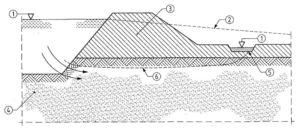
70 Brussels, February 2008 Dissemination of information workshop 19 Annex B.3 Examples of recommendations for the spacing and depth of investigations (1) The following spacing of investigation points should be used as guidance: for high-rise and industrial structures, a grid pattern with points at 15 m to 40 m distance; for large-area structures, a grid pattern with points at not more than 60 m distance; for linear structures (roads, railways, channels, pipelines, dikes, tunnels, retaining walls), a spacing of 20 m to 200 m; for special structures (e.g. bridges, stacks, machinery foundations), two to six investigation points per foundation; for dams and weirs, 25 m to 75 m distance, along vertical sections. Brussels, February 2008 Dissemination of information workshop 20 Annex B.3 Examples of recommendations for the spacing and depth of investigations (2) For the investigation depth z a the following values should be used as guidance. (The reference level for z a is the lowest point of the foundation of the structure or structural element, or the excavation base.) Where more than one alternative is specified for establishing z a, the one which yields the largest value should be applied. NOTE For very large or highly complex projects, some of the investigation points should extend to greater depths than those specified under Annex B.3 (5) to B.3 (13). Brussels, February 2008 Dissemination of information workshop 21 Brussels, February 2008 Dissemination of information workshop 22 Annex B.3: Spacing and depth of investigations (5) For high-rise structures and civil engineering projects, the larger value of the following conditions should be applied: z a 6 m; z a 3,0 b F. where b F is the smaller side length of the foundation. Annex B.3: Spacing and depth of investigations (6) For raft foundations and structures with several foundation elements whose effects in deeper strata are superimposed on each other: z a 1,5 b B where b B is the smaller side of the structure, Brussels, February 2008 Dissemination of information workshop 23 Annex B.3: Spacing and depth of investigations Brussels, February 2008 Dissemination of information workshop 24 Annex B.3: Spacing and depth of investigations Road Trench (7) Embankments and cuttings, the larger value of the following conditions should be met: a) For dams: 0,8h < z a < 1,2h z a 6 m where h is the embankment height. b) For cuttings: z a 2,0 m z a 0,4h where h is the dam height or depth of cutting. For roads and airfields: z a 2 m below the proposed formation level. For trenches and pipelines, the larger value of: z a 2 m below the invert level; z a 1,5b Ah where b Ah is the width of excavation.
71 Brussels, February 2008 Dissemination of information workshop 25 Brussels, February 2008 Dissemination of information workshop 26 Annex B.3: Spacing and depth of investigations (9) For small tunnels and caverns: b Ab < z a < 2,0b Ab where b Ab is the width of excavation. The groundwater conditions described in (10) b) should also be taken into account. Annex B.3: Spacing and depth of investigations (10) Excavations a) Where the piezometric surface and the groundwater tables are below the excavation base, the larger value of the following conditions should be met: z a 0,4h z a (t + 2,0) m where: t is the embedded length of the support; and h is the excavation depth. Brussels, February 2008 Dissemination of information workshop 27 Annex B.3: Spacing and depth of investigations b) Where the piezometric surface and the groundwater tables are above the excavation base, the larger value of the following conditions should be met: z a (1,0H + 2,0) m z a (t + 2,0) m where H is the height of the groundwater level above the excavation base; and t is the embedded length of the support. Brussels, February 2008 Dissemination of information workshop 28 Annex B.3: Spacing and depth of investigations (12) For cut-off walls: z a 2 m below the surface of the stratum impermeable to groundwater. Brussels, February 2008 Dissemination of information workshop 29 Annex B.3: Spacing and depth of investigations (13) For piles the following three conditions should be met: z a 1,0b g z a 5,0 m z a 3D F where D F is the pile base diameter; and b g is the smaller side of the rectangle circumscribing the group of piles forming the foundation at the level of the pile base. Brussels, February 2008 Dissemination of information workshop Sampling (2)P For identification and classification of the ground, at least one borehole or trial pit with sampling shall be available. Samples shall be obtained from every separate ground layer influencing the behaviour of the structure. (3) Sampling may be replaced by field tests if there is enough local experience to correlate the field tests with the ground conditions to ensure unambiguous interpretation of the results. 2 Planning of ground investigations (7) Samples should be taken at any change of stratum and at a specified spacing, usually not larger than 3 m. In inhomogeneous soil, or if a detailed definition of the ground conditions is required, continuous sampling by drilling should be carried out or samples recovered at very short intervals.
72 Brussels, February 2008 Dissemination of information workshop 31 2 Planning of ground investigations 2.5 Controlling and monitoring (1)P A number of checks and additional tests shall be made during the construction and execution of the project, when relevant, in order to check that the ground conditions agree with those determined in the design investigations and that the properties of the delivered construction materials and the construction works correspond to those presumed or specified. (2)P The following control measures shall be applied: check of ground profile when excavating; inspection of the bottom of the excavation. Brussels, February 2008 Dissemination of information workshop Soil sampling (1)P Samples shall contain all the mineral constituents of the strata from which they have been taken. They shall not be contaminated by any material from other strata or from additives used during the sampling procedure. (2)P Three sampling method categories shall be considered (EN ISO ), depending on the desired sample quality as follows: category A sampling methods: samples of quality class 1 to 5 can be obtained; category B sampling methods: samples of quality class 3 to 5 can be obtained; category C sampling methods: only samples of quality class 5 can be obtained. Brussels, February 2008 Dissemination of information workshop Soil sampling (6)P Soil samples for laboratory tests are divided in five quality classes with respect to the soil properties that are assumed to remain unchanged during sampling and handling, transport and storage. Brussels, February 2008 Dissemination of information workshop Soil sampling Table Quality classes of soil samples for laboratory testing and sampling categories to be used Soil properties / quality class Unchanged soil properties particle size water content density, density index, permeability compressibility, shear strength Properties that can be determined: sequence of layers boundaries of strata broad boundaries of strata fine Atterberg limits, particle density, organic content water content density, density index, porosity, permeability compressibility, shear strength Sampling category according to EN ISO A B C Brussels, February 2008 Dissemination of information workshop 35 4 Field tests in soil and rock 4.1 General 4.2 General requirements 4.3 Cone penetration and piezocone penetration tests (CPT, CPTU) 4.4 Pressuremeter tests (PMT) 4.5 Flexible dilatometer test (FDT) 4.6 Standard penetration test SPT 4.7 Dynamic probing tests (DP) 4.8 Weight sounding test (WST) 4.9 Field vane test (FVT) 4.10 Flat dilatometer test (DMT) 4.11 Plate loading test (PLT) Brussels, February 2008 Dissemination of information workshop Cone penetration tests (1) The objective of the cone penetration test (CPT) is to determine the resistance of soil and soft rock to the penetration of a cone and the local friction on a sleeve. (2)P The CPT consists of pushing a cone penetrometer vertically into the soil using a series of push rods. The cone penetrometer shall be pushed into the soil at a constant rate of penetration. The cone penetrometer comprises the cone and if appropriate a cylindrical shaft or friction sleeve. The penetration resistance of the cone q c as well as, if appropriate, the local friction on the friction sleeve shall be measured.
 Brussels, 18-20 February 2008 Dissemination of information workshop 38 4.")
73 Brussels, February 2008 Dissemination of information workshop Cone penetration and piezocone penetration tests (CPT, CPTU) Brussels, February 2008 Dissemination of information workshop Cone penetration and piezocone penetration tests (CPT, CPTU) q c cone resistance (bar) f s sleeve friction (bar) friction ratio R ft =100 F s /q c Sandy fill Porewater pressure measurement: u 1 : on the cone face u 2 : at the cylindrical extension of the cone u 3 : directly behind the friction sleeve fine and medium sand Glacial till Brussels, February 2008 Dissemination of information workshop Cone penetration and piezocone penetration tests (CPT, CPTU) q c cone penetration resistance friction ratio R ft = f S /q c 100 friction ratio R ft = f S /q c 100 Brussels, February 2008 Dissemination of information workshop Cone penetration tests - Annex D D.1 Example for deriving values of the effective angle of shearing resistance and drained Young s modulus D.2 Example of a correlation between the cone penetration resistance and the effective angle of shearing resistance D.3 Example of a method to determine the settlement for spread foundations D.4 Example of a correlation between the oedometer modulus and the cone penetration resistance D.5 Examples of establishing the stress-dependent oedometer modulus from CPT results D.6 Example of a correlation between compressive resistance of a single pile and cone penetration resistance D.7 Example of a method to determine the compressive resistance of a single pile. Brussels, February 2008 Dissemination of information workshop 41 Annex D Cone penetration tests Table D.1: Effective angle of shearing resistance ( ) and drained Young s modulus of elasticity (E ) from cone penetration resistance (q c ) a Values given are valid for sands. For silty soil a reduction of 3 should be made. For gravels 2 should be added. b E' is an approximation to the stress and time dependent secant modulus. Values given for the drained modulus correspond to settlements for 10 years. They are obtained assuming that the vertical stress distribution follows the 2:1 approximation. Brussels, February 2008 Dissemination of information workshop 42 5 Laboratory tests 5.1 General 5.2 General requirements for laboratory tests 5.3 Preparation of soil specimens for testing 5.4 Preparation of rock specimens for testing 5.5 Tests for classification, identification and description of soil 5.6 Chemical testing of soil and groundwater 5.7 Strength index testing of soil 5.8 Strength testing of soil 5.9 Compressibility and deformation testing of soil 5.10 Compaction testing of soil 5.11 Permeability testing of soil 5.12 Tests for classification of rocks 5.13 Swelling testing of rock material 5.14 Strength testing of rock material

74 Brussels, February 2008 Dissemination of information workshop Strength testing of soil - Annex P Table P.1 Triaxial compression tests. Recommended minimum number of tests for one soil stratum Brussels, February 2008 Dissemination of information workshop Compressibility and deformation testing of soil - Annex Q Table Q.1 Incremental oedometer test. Recommended minimum number of tests for one soil stratum Variability in Comparable experience oedometer modulus E oed (in the relevant stress range) None Medium Extensive Range of values of E oed 50 % % < Range of values of E oed < 50 % Range of values of E oed 20 % a a One oedometer test and classification tests to verify compatibility with comparable knowledge (see Q.1 (2)). Brussels, February 2008 Dissemination of information workshop 45 Brussels, February 2008 Dissemination of information workshop Permeability testing of soil Annex S Table S.1 - Permeability tests. Recommended minimum number of soil specimens to be tested for one soil stratum. Variability in measured coefficient of permeability (k) k max /k min > < k max /k min 100 k max /k min 10 Comparable experience None a A single test and classification tests to verify compatibility with existing knowledge Medium Extensive a 6 Ground investigation report 6.1 General requirements 6.2 Presentation of geotechnical information 6.3 Evaluation of geotechnical information 6.4 Establishment of derived values Brussels, February 2008 Dissemination of information workshop 47 Brussels, February 2008 Dissemination of information workshop 48 6 Ground investigation report 6.1 General requirements (1)P The results of a geotechnical investigation shall be compiled in the Ground Investigation Report which shall form a part of the Geotechnical Design Report. (2)P The Ground Investigation Report shall consist of, if appropriate a presentation of all available geotechnical information including geological features and relevant data; a geotechnical evaluation of the information, stating the assumptions made in the interpretation of the test results. 6 Ground investigation report 6.2 Presentation of geotechnical information (1)P The presentation of geotechnical information shall include a factual account of all field and laboratory investigations. (2) The factual account should include the following information, as relevant:......
Seminar Worked examples on Bridge Design with Eurocodes
 1 EU-Russia Regulatory Dialogue: Construction Sector Subgroup Seminar Worked examples on Bridge Design with Eurocodes St-Petersburg, 17-18 April 2013 Organized and supported by European Commission DG Joint
EN Eurocode 7. Section 3 Geotechnical Data Section 6 Spread Foundations. Trevor L.L. Orr Trinity College Dublin Ireland.
 EN 1997 1: Sections 3 and 6 Your logo Brussels, 18-20 February 2008 Dissemination of information workshop 1 EN 1997-1 Eurocode 7 Section 3 Geotechnical Data Section 6 Spread Foundations Trevor L.L. Orr
Practical Design to Eurocode 2. The webinar will start at 12.30
 Practical Design to Eurocode 2 The webinar will start at 12.30 Course Outline Lecture Date Speaker Title 1 21 Sep Jenny Burridge Introduction, Background and Codes 2 28 Sep Charles Goodchild EC2 Background,
Worked examples. Dr. Bernd Schuppener German Federal Waterways Engineering and Research Institute, Karlsruhe Past Chairman of CEN TC250/SC 7
 13-14 June 2013, Dublin Worked examples HYD and UPL limit it states Dr. Bernd Schuppener German Federal Waterways Engineering and Research Institute, Karlsruhe Past Chairman of CEN TC250/SC 7 Worked example:
Session 3. Calculation Models. EQU, UPL and HYD. Design of Pile Foundations
 1 Session 3 Calculation Models EQU, UPL and HYD Design of Pile Foundations (Killiney Bay) 2 SLS and Settlement Calculations (Dalkey Island) Summary of ULS Designs Undrained width (m) Drained width (m)
The Concepts of Eurocode 7 for Harmonised Geotechnical Design in Europe
 1 The Concepts of Eurocode 7 for Harmonised Geotechnical Design in Europe by Trevor Orr Trinity College Dublin at Politechnika Wrocławska Studia Doktoranckie on 8 th to 12 th February 2010 2 Day 2 Development
Engineeringmanuals. Part2
 Engineeringmanuals Part2 Engineering manuals for GEO5 programs Part 2 Chapter 1-12, refer to Engineering Manual Part 1 Chapter 13. Pile Foundations Introduction... 2 Chapter 14. Analysis of vertical load-bearing
O Dr Andrew Bond (Geocentrix)
") DECODING EUROCODES 2 + 7: DESIGN SG OF FOUNDATIONS O Dr Andrew Bond (Geocentrix) Outline of talk April 2010: the death of British Standards? UK implementation of Eurocodes Verification of strength: limit
DECODING EUROCODES 2 + 7: DESIGN SG OF FOUNDATIONS O Dr Andrew Bond (Geocentrix) Outline of talk April 2010: the death of British Standards? UK implementation of Eurocodes Verification of strength: limit
Session 4. Risk and Reliability. Design of Retaining Structures. Slopes, Overall Stability and Embankments. (Blarney Castle)
") Session 4 Risk and Reliability Design of Retaining Structures Slopes, Overall Stability and Embankments (Blarney Castle) 1 2 Session 4a Risk and reliability Complexity and Geotechnical Risk The complexity
Session 4 Risk and Reliability Design of Retaining Structures Slopes, Overall Stability and Embankments (Blarney Castle) 1 2 Session 4a Risk and reliability Complexity and Geotechnical Risk The complexity
Introduction to The Design Example and EN Basis of Design
 EUROCODES Bridges: Background and applications St Petersburg April 2011 1 Introduction to The Design Example and EN 1990 - Basis of Design Professor Steve Denton Engineering Director, Parsons Brinckerhoff
Erratum. Chapter 4 - Earth and water pressure 26. Chapter Area loads. q a. c+d ϕ'/2. Piling Handbook, 9th edition (2016)
") Chapter 4 - Earth and water pressure 26 Chapter 4.9.15. Area loads z x q ϕ' a c+d 45 + ϕ'/2 Fig. 4.3. Force distribution area lords. Chapter 5 - Design of steel sheetpile structures 22 Chapter 5.8.3. Surcharge
Chapter 4 - Earth and water pressure 26 Chapter 4.9.15. Area loads z x q ϕ' a c+d 45 + ϕ'/2 Fig. 4.3. Force distribution area lords. Chapter 5 - Design of steel sheetpile structures 22 Chapter 5.8.3. Surcharge
Project: Cantilever Steel SheetPile Retaining Wall Analysis & Design, Free Earth Support In accordance Eurocode 7.
 App'd by Construction Stages Name Term Objects present in this stage Stage 1 Long Wall 1 (Generated) (Generated) On retained side: Ground 1 (Generated), Borehole 1 (Generated), On excavated side: Excavation
SOIL MECHANICS: palgrave. Principles and Practice. Graham Barnes. macmiiian THIRD EDITION
 SOIL MECHANICS: Principles and Practice THIRD EDITION Graham Barnes palgrave macmiiian 'running Contents Preface xii Fine soil 19 List of symbols xiv Mass structure 21 Note on units xix Degree of weathering
Analysis of the horizontal bearing capacity of a single pile
 Engineering manual No. 16 Updated: 07/2018 Analysis of the horizontal bearing capacity of a single pile Program: Soubor: Pile Demo_manual_16.gpi The objective of this engineering manual is to explain how
Reliability-based ultimate limit state design in finite element methods
 Delft University of Technology Faculty of Civil Engineering and Geosciences Section Geo-Engineering, Civil Engineering Reliability-based ultimate limit state design in finite element methods Author: Stefan
Jose Brito, Cenor, Portugal
 Jose Brito, Cenor, Portugal Carsten S. Sorensen, COWI, Denmark In this example it is asked to design a square pad foundation according to Eurocode 7. The aim is the evaluation of the foundation width with
Safety Concepts and Calibration of Partial Factors in European and North American Codes of Practice
 Safety Concepts and Calibration of Partial Factors in European and North American Codes of Practice The Dutch approach on Geotechnical Design by Eurocode 7 Adriaan van Seters Hein Jansen Fugro GeoServices
KDOT Geotechnical Manual Edition. Table of Contents
 KDOT Geotechnical Manual 2007 Edition The KDOT Geotechnical Manual is available two volumes. Both volumes are very large electronic (pdf) files which may take several minutes to download. The table of
Design Example 2.2. Pad foundation with inclined eccentric load on boulder clay
 Design Example 2.2. Pad foundation with inclined eccentric load on boulder clay 1. Obtaining characteristic value of undrained shear strength Due to conditions given in the example a decision was made
Tower Cranes & Foundations The Interface & CIRIA C654 Stuart Marchand C.Eng. FICE FIStructE Director Wentworth House Partnership
 Tower Cranes & Foundations The Interface & CIRIA C654 Stuart Marchand C.Eng. FICE FIStructE Director Wentworth House Partnership EXAMPLES OF TOWER CRANE FOUNDATION TYPES Rail mounted Pad Base Piled Base
Geotechnical issues in seismic assessments: When do I need a geotechnical specialist?
 Geotechnical issues in seismic assessments: When do I need a geotechnical specialist? B.H. Rama & S.J. Palmer Tonkin & Taylor Ltd (T+T), Wellington, New Zealand. 2016 NZSEE Conference ABSTRACT: The Canterbury
Verification of a Micropile Foundation
 Engineering manual No. 36 Update 02/2018 Verification of a Micropile Foundation Program: File: Pile Group Demo_manual_en_36.gsp The objective of this engineering manual is to explain the application of
INTI COLLEGE MALAYSIA
 EGC373 (F) / Page 1 of 5 INTI COLLEGE MALAYSIA UK DEGREE TRANSFER PROGRAMME INTI ADELAIDE TRANSFER PROGRAMME EGC 373: FOUNDATION ENGINEERING FINAL EXAMINATION : AUGUST 00 SESSION This paper consists of
Seismic design of bridges
 NATIONAL TECHNICAL UNIVERSITY OF ATHENS LABORATORY FOR EARTHQUAKE ENGINEERING Seismic design of bridges Lecture 3 Ioannis N. Psycharis Capacity design Purpose To design structures of ductile behaviour
INTRODUCTION TO STATIC ANALYSIS PDPI 2013
 INTRODUCTION TO STATIC ANALYSIS PDPI 2013 What is Pile Capacity? When we load a pile until IT Fails what is IT Strength Considerations Two Failure Modes 1. Pile structural failure controlled by allowable
GEOTECHNICAL ENGINEERING ECG 503 LECTURE NOTE ANALYSIS AND DESIGN OF RETAINING STRUCTURES
 GEOTECHNICAL ENGINEERING ECG 503 LECTURE NOTE 07 3.0 ANALYSIS AND DESIGN OF RETAINING STRUCTURES LEARNING OUTCOMES Learning outcomes: At the end of this lecture/week the students would be able to: Understand
Reliability analysis of geotechnical risks
 Reliability analysis of geotechnical risks Lazhar Belabed*, Hacene Benyaghla* * Department of Civil Engineering and Hydraulics, University of Guelma, Algeria Abstract The evaluation of safety or reliability
Landslide FE Stability Analysis
 Landslide FE Stability Analysis L. Kellezi Dept. of Geotechnical Engineering, GEO-Danish Geotechnical Institute, Denmark S. Allkja Altea & Geostudio 2000, Albania P. B. Hansen Dept. of Geotechnical Engineering,
Civil Engineering Design (1) Design of Reinforced Concrete Columns 2006/7
 Design of Reinforced Concrete Columns 2006/7") Civil Engineering Design (1) Design of Reinforced Concrete Columns 2006/7 Dr. Colin Caprani, Chartered Engineer 1 Contents 1. Introduction... 3 1.1 Background... 3 1.2 Failure Modes... 5 1.3 Design Aspects...
Civil Engineering Design (1) Design of Reinforced Concrete Columns 2006/7 Dr. Colin Caprani, Chartered Engineer 1 Contents 1. Introduction... 3 1.1 Background... 3 1.2 Failure Modes... 5 1.3 Design Aspects...
30/03/2011. Eurocode 7 Today and Tomorrow. Ground structures t Slope and Retaining wall design in the Netherlands. Contents
 Eurocode 7 Today and Tomorrow Ground structures t Slope and Retaining wall design in the Netherlands Adriaan van Seters Hein Jansen Fugro Ingenieursbureau BV The Netherlands Contents Design Approach 3
Foundation Engineering Prof. Dr N.K. Samadhiya Department of Civil Engineering Indian Institute of Technology Roorkee
 Foundation Engineering Prof. Dr N.K. Samadhiya Department of Civil Engineering Indian Institute of Technology Roorkee Module 01 Lecture - 03 Shallow Foundation So, in the last lecture, we discussed the
Introduction to Soil Mechanics
 Introduction to Soil Mechanics Sela Sode and Colin Jones WILEY Blackwell Contents Preface Dedication and Acknowledgments List of Symbols Soil Structure 1.1 Volume relationships 1.1.1 Voids ratio (e) 1.1.2
EUROCODE EN SEISMIC DESIGN OF BRIDGES
 Brussels, 18-20 February 2008 Dissemination of information workshop 1 EUROCODE EN1998-2 SEISMIC DESIGN OF BRIDGES Basil Kolias Basic Requirements Brussels, 18-20 February 2008 Dissemination of information
Two Case Studies on Soil Nailed Slope Failures
 Two Case Studies on Soil Nailed Slope Failures Liew, Shaw-Shong 1 & Liong, Chee-How 2 1 Director, Gue & Partners Sdn Bhd, Kuala Lumpur, Malaysia 2 Senior Engineer, Gue & Partners Sdn Bhd, Kuala Lumpur,
SHEET PILE WALLS. Mehdi Mokhberi Islamic Azad University
 SHEET PILE WALLS Mehdi Mokhberi Islamic Azad University Lateral Support In geotechnical engineering, it is often necessary to prevent lateral soil movements. Tie rod Anchor Sheet pile Cantilever retaining
Structural Fire Design according to Eurocodes
 Brussels, 18-20 February 2008 Dissemination of information workshop 1 Structural Fire Design according to Eurocodes Joël KRUPPA CTICM Coordinator CEN TC 250 / Horizontal Group "FIRE" ESSENTIAL REQUIREMENTS
LIVING REINFORCED SOIL - AN ECOLOGICAL METHOD TO STABILISE SLOPES
 75 Improvement of Soil Properties, Bratislava on June 4 5, 2007 LIVING REINFORCED SOIL - AN ECOLOGICAL METHOD TO STABILISE SLOPES Bernd Schuppener Abstract: Living Reinforced Soil is a method of stabilising
STRUCTURAL ANALYSIS CHAPTER 2. Introduction
 CHAPTER 2 STRUCTURAL ANALYSIS Introduction The primary purpose of structural analysis is to establish the distribution of internal forces and moments over the whole part of a structure and to identify
Gapping effects on the lateral stiffness of piles in cohesive soil
 Gapping effects on the lateral stiffness of piles in cohesive soil Satyawan Pranjoto Engineering Geology, Auckland, New Zealand. M. J. Pender Department of Civil and Environmental Engineering, University
CHAPTER 8 CALCULATION THEORY
 CHAPTER 8 CALCULATION THEORY. Volume 2 CHAPTER 8 CALCULATION THEORY Detailed in this chapter: the theories behind the program the equations and methods that are use to perform the analyses. CONTENTS CHAPTER
SERVICEABILITY LIMIT STATE DESIGN
 CHAPTER 11 SERVICEABILITY LIMIT STATE DESIGN Article 49. Cracking Limit State 49.1 General considerations In the case of verifications relating to Cracking Limit State, the effects of actions comprise
Bored piles in clay and Codes of Practice. Malcolm Bolton
 Bored piles in clay and Codes of Practice Malcolm Bolton Background: design and decision-making Why is design not yet evidence-based? Reliance on past practice, rather than validation. Safety factors have
Appraisal of Soil Nailing Design
 Indian Geotechnical Journal, 39(1), 2009, 81-95 Appraisal of Soil Nailing Design G. L. Sivakumar Babu * and Vikas Pratap Singh ** Introduction Geotechnical engineers largely prefer soil nailing as an efficient
TABLE OF CONTENTS CHAPTER TITLE PAGE TITLE PAGE DECLARATION DEDIDATION ACKNOWLEDGEMENTS ABSTRACT ABSTRAK
 TABLE OF CONTENTS CHAPTER TITLE PAGE TITLE PAGE DECLARATION DEDIDATION ACKNOWLEDGEMENTS ABSTRACT ABSTRAK TABLE OF CONTENTS LIST OF TABLE LIST OF FIGURES LIST OF SYMBOLS LIST OF APENDICES i ii iii iv v
RAMWALL DESIGN METHODOLOGY
 RAMWALL DESIGN METHODOLOGY Submitted by:. June 005 CONTENTS 1. INTRODUCTION 1 Page. REFERENCED DOCUMENTS & ABBREVIATIONS 1 3 DESIGN METHODOLOGY / THEORY 3.1 General 3. Internal Analysis 4 3.3 External
Module 6. Approximate Methods for Indeterminate Structural Analysis. Version 2 CE IIT, Kharagpur
 Module 6 Approximate Methods for Indeterminate Structural Analysis Lesson 35 Indeterminate Trusses and Industrial rames Instructional Objectives: After reading this chapter the student will be able to
The Bearing Capacity of Soils. Dr Omar Al Hattamleh
 The Bearing Capacity of Soils Dr Omar Al Hattamleh Example of Bearing Capacity Failure Omar Play the move of bearing Capacity failure The Philippine one Transcona Grain Silos Failure - Canada The Bearing
Seabed instability and 3D FE jack-up soil-structure interaction analysis
 Seabed instability and 3D FE jack-up soil-structure interaction analysis Lindita Kellezi, GEO Danish Geotechnical Institute, Denmark Gregers Kudsk, Maersk Contractors, Denmark Hugo Hofstede, Marine Structure
Foundations of High Rise Buildings
 Foundations of High Rise Buildings Prof. Dr.-Ing. Yasser El-Mossallamy Professor of Geotechnical Engineering Ain Shams Univ. Cairo, Egypt c/o Arcadis Consult, Germany y.el-mossallamy@arcadis.de Slide:
J. Paul Guyer, P.E., R.A.
 J. Paul Guyer, P.E., R.A. Paul Guyer is a registered mechanical engineer, civil engineer, fire protection engineer and architect with over 35 years experience in the design of buildings and related infrastructure.
Harmonized European standards for construction in Egypt
 Harmonized European standards for construction in Egypt EN 1998 - Design of structures for earthquake resistance Jean-Armand Calgaro Chairman of CEN/TC250 Organised with the support of the Egyptian Organization
file:///d /suhasini/suha/office/html2pdf/ _editable/slides/module%202/lecture%206/6.1/1.html[3/9/2012 4:09:25 PM]
![file:///d /suhasini/suha/office/html2pdf/ _editable/slides/module%202/lecture%206/6.1/1.html[3/9/2012 4:09:25 PM]](/thumbs/96/126781421.jpg "file:///d /suhasini/suha/office/html2pdf/ _editable/slides/module%202/lecture%206/6.1/1.html[3/9/2012 4:09:25 PM]") Objectives_template Objectives In this section you will learn the following Introduction Different Theories of Earth Pressure Lateral Earth Pressure For At Rest Condition Movement of the Wall Different
Objectives_template Objectives In this section you will learn the following Introduction Different Theories of Earth Pressure Lateral Earth Pressure For At Rest Condition Movement of the Wall Different
Dynamic Response of EPS Blocks /soil Sandwiched Wall/embankment
 Proc. of Second China-Japan Joint Symposium on Recent Development of Theory and Practice in Geotechnology, Hong Kong, China Dynamic Response of EPS Blocks /soil Sandwiched Wall/embankment J. C. Chai 1
Tipologia e dimensionamento estrutural das fundações de Torres de Linhas de Alta Tensão em diferentes condições geotécnicas
 Tipologia e dimensionamento estrutural das fundações de Torres de Linhas de Alta Tensão em diferentes condições geotécnicas Typology and structural design of High Tension Electric Lines foundations for
Probabilistic assessment of geotechnical objects by means of MONTE CARLO METHOD. Egidijus R. Vaidogas
 Probabilistic assessment of geotechnical objects by means of MONTE CARLO METHOD Egidijus R. Vaidogas Vilnius Gediminas technical university, Lithuania ERASMUS/SOCRATES program, 2007 What is the principal
Bridge deck modelling and design process for bridges
 EU-Russia Regulatory Dialogue Construction Sector Subgroup 1 Bridge deck modelling and design process for bridges Application to a composite twin-girder bridge according to Eurocode 4 Laurence Davaine
Ch 4a Stress, Strain and Shearing
 Ch. 4a - Stress, Strain, Shearing Page 1 Ch 4a Stress, Strain and Shearing Reading Assignment Ch. 4a Lecture Notes Sections 4.1-4.3 (Salgado) Other Materials Handout 4 Homework Assignment 3 Problems 4-13,
Theory of Shear Strength
 SKAA 1713 SOIL MECHANICS Theory of Shear Strength Prepared by, Dr. Hetty 1 SOIL STRENGTH DEFINITION Shear strength of a soil is the maximum internal resistance to applied shearing forces The maximum or
The new French standard for the application of Eurocode 7 for deep foundations. Roger Frank, Ecole des ponts Sébastien Burlon, IFSTTAR
 The new French standard for the application of Eurocode 7 for deep foundations Roger Frank, Ecole des ponts Sébastien Burlon, IFSTTAR Outline Introduction Aspects of pile design following Eurocode 7 (EN
Chapter 6 Bearing Capacity
 Chapter 6 Bearing Capacity 6-1. Scope This chapter provides guidance for the determination of the ultimate and allowable bearing stress values for foundations on rock. The chapter is subdivided into four
Theory of Shear Strength
 MAJ 1013 ADVANCED SOIL MECHANICS Theory of Shear Strength Prepared by, Dr. Hetty 1 Strength of different materials Steel Concrete Soil Tensile strength Compressive strength Shear strength Complex behavior
cyclic loading in Germany
 Note to actual al design of micropiles under axial cyclic loading in Germany according to DIN 1054 and further guidelines Jennifer Kleih 9th International Workshop on Micropiles London 13th May 2009 Outline
Analysis of a single pile settlement
 Engineering manual No. 14 Updated: 06/2018 Analysis of a single pile settlement Program: Pile File: Demo_manual_14.gpi The objective of this engineering manual is to explain the application of the GEO
Clayey sand (SC)
") Pile Bearing Capacity Analysis / Verification Input data Project Task : PROJECT: "NEW STEAM BOILER U-5190 Part : A-1 Descript. : The objective of this Analysis is the Pile allowable bearing Capacity Analysis
Pile Bearing Capacity Analysis / Verification Input data Project Task : PROJECT: "NEW STEAM BOILER U-5190 Part : A-1 Descript. : The objective of this Analysis is the Pile allowable bearing Capacity Analysis
Structural Calculations for Juliet balconies using BALCONY 2 System (Aerofoil) handrail. Our ref: JULB2NB Date of issue: March 2017
 handrail. Our ref: JULB2NB Date of issue: March 2017") Juliet balconies using BALCONY 2 System (Aerofoil) handrail PAGE 1 (ref: JULB2NB280317) Structural Calculations for Juliet balconies using BALCONY 2 System (Aerofoil) handrail Our ref: JULB2NB280317 Date
Juliet balconies using BALCONY 2 System (Aerofoil) handrail PAGE 1 (ref: JULB2NB280317) Structural Calculations for Juliet balconies using BALCONY 2 System (Aerofoil) handrail Our ref: JULB2NB280317 Date
Lesson 25. Static Pile Load Testing, O-cell, and Statnamic. Reference Manual Chapter 18
 Lesson 25 Static Pile Load Testing, O-cell, and Statnamic Reference Manual Chapter 18 STATIC LOAD TESTING Most accurate method to determine static pile capacity Perform at design or construction stage
Eurocode 7 from soil mechanics to rock mechanics. Luís Lamas, LNEC, Lisbon, Portugal Didier Virely, CEREMA, Toulouse, France
 Eurocode 7 from soil mechanics to rock mechanics Luís Lamas, LNEC, Lisbon, Portugal Didier Virely, CEREMA, Toulouse, France Contents 1. The discontinuous nature of rock mass 2. Design methods 3. Calculation
RELIABILITY ASSESSMENT OF EXISTING STRUCTURES
 1. Introduction RELIABILITY ASSESSMENT OF EXISTING STRUCTURES EN Eurocodes, presently being implemented into the system of national standards nearly in the whole Europe, are particularly intended for the
Design of reinforced concrete sections according to EN and EN
 Design of reinforced concrete sections according to EN 1992-1-1 and EN 1992-2 Validation Examples Brno, 21.10.2010 IDEA RS s.r.o. South Moravian Innovation Centre, U Vodarny 2a, 616 00 BRNO tel.: +420-511
Observational Methods and
 Observational Methods and NATM System for Observational approach to tunnel design Eurocode 7 (EC7) includes the following remarks concerning an observational method. Four requirements shall all be made
INVESTIGATION OF SATURATED, SOFT CLAYS UNDER EMBANKMENTS. Zsolt Rémai Budapest University of Technology and Economics Department of Geotechnics
 INVESTIGATION OF SATURATED, SOFT CLAYS UNDER EMBANKMENTS PhD thesis Zsolt Rémai Budapest University of Technology and Economics Department of Geotechnics Budapest December, 2012 1. IMPORTANCE OF THE RESEARCH
Chapter (11) Pile Foundations
 Pile Foundations") Chapter (11) Introduction Piles are structural members that are made of steel, concrete, or timber. They are used to build pile foundations (classified as deep foundations) which cost more than shallow
Chapter (11) Introduction Piles are structural members that are made of steel, concrete, or timber. They are used to build pile foundations (classified as deep foundations) which cost more than shallow
Composite bridge design (EN1994-2) Bridge modelling and structural analysis
 Bridge modelling and structural analysis") EUROCODES Bridges: Background and applications Dissemination of information for training Vienna, 4-6 October 2010 1 Composite bridge design (EN1994-2) Bridge modelling and structural analysis Laurence
EUROCODES Bridges: Background and applications Dissemination of information for training Vienna, 4-6 October 2010 1 Composite bridge design (EN1994-2) Bridge modelling and structural analysis Laurence
English version Version Française Deutsche Fassung
 EUROPEAN STANDARD NORME EUROPÉENNE EUROPÄISCHE NORM EN 1997-1:2004/AC February 2009 Février 2009 Februar 2009 ICS 93.020; 91.010.30 English version Version Française Deutsche Fassung Eurocode 7: Geotechnical
Mitigation measures: stabilization works
 Intensive Course in Quantitative Landslide Risk Assessment and Risk management Mitigation measures: stabilization works E.E. Alonso Department of Geotechnical Engineering and Geosciences UPC, Barcelona
STUDY OF THE BEHAVIOR OF PILE GROUPS IN LIQUEFIED SOILS
 STUDY OF THE BEHAVIOR OF PILE GROUPS IN LIQUEFIED SOILS Shin-Tower Wang 1, Luis Vasquez 2, and Lymon C. Reese 3, Honorary Member,, ASCE ABSTRACT : 1&2 President & Project Manager, Ensoft, Inc. Email: ensoft@ensoftinc.com
Deep Foundations 2. Load Capacity of a Single Pile
 Deep Foundations 2 Load Capacity of a Single Pile All calculations of pile capacity are approximate because it is almost impossible to account for the variability of soil types and the differences in the
CHAPTER 8 ANALYSES OF THE LATERAL LOAD TESTS AT THE ROUTE 351 BRIDGE
 CHAPTER ANALYSES OF THE LATERAL LOAD TESTS AT THE ROUTE 351 BRIDGE.1 INTRODUCTION An important objective of this research is to determine whether accurate analyses of the lateral load-deflection behavior
BEARING CAPACITY SHALLOW AND DEEP FOUNDATIONS
 BEARING CAPACITY SHALLOW AND DEEP FOUNDATIONS CONTENTS: 1.0 INTRODUCTION 2.0 SHALLOW FOUNDATIONS 2.1 Design criteria 2.2 Spreading load 2.3 Types of foundations 2.4 Ground failure modes 2.5 Definitions
8.1. What is meant by the shear strength of soils? Solution 8.1 Shear strength of a soil is its internal resistance to shearing stresses.
 8.1. What is meant by the shear strength of soils? Solution 8.1 Shear strength of a soil is its internal resistance to shearing stresses. 8.2. Some soils show a peak shear strength. Why and what type(s)
CONTROLLING FACTORS BASIC ISSUES SAFETY IN OPENCAST MINING WITH SPECIAL REFERENCE TO SLOPE STABILITY
 SAFETY IN OPENCAST MINING WITH SPECIAL REFERENCE TO SLOPE STABILITY CONTROLLING FACTORS Dr. J C. JHANWAR Sr. Principal Scientist CSIR-Central Institute of Mining & Fuel Research Regional Centre, Nagpur
Slenderness Effects for Concrete Columns in Sway Frame - Moment Magnification Method (CSA A )
") Slenderness Effects for Concrete Columns in Sway Frame - Moment Magnification Method (CSA A23.3-94) Slender Concrete Column Design in Sway Frame Buildings Evaluate slenderness effect for columns in a
Slenderness Effects for Concrete Columns in Sway Frame - Moment Magnification Method (CSA A23.3-94) Slender Concrete Column Design in Sway Frame Buildings Evaluate slenderness effect for columns in a
Laboratory Testing Total & Effective Stress Analysis
 SKAA 1713 SOIL MECHANICS Laboratory Testing Total & Effective Stress Analysis Prepared by: Dr. Hetty Mohr Coulomb failure criterion with Mohr circle of stress 2 ' 2 ' ' ' 3 ' 1 ' 3 ' 1 Cot Sin c ' ' 2
Design of foundations in France with the use of Ménard pressuremeter tests (MPM)
") Gersevanovskie Chteniya Laboratory and in-situ soil investigation Moscow, 15 April 2009 Design of foundations in France with the use of Ménard pressuremeter tests (MPM) Roger FRANK Ecole nationale des
Gersevanovskie Chteniya Laboratory and in-situ soil investigation Moscow, 15 April 2009 Design of foundations in France with the use of Ménard pressuremeter tests (MPM) Roger FRANK Ecole nationale des
SLOPE STABILITY EVALUATION AND ACCEPTANCE STANDARDS
 INFORMATION BULLETIN / PUBLIC - BUILDING CODE REFERENCE NO.: LAMC 98.0508 Effective: 1-26-84 DOCUMENT NO. P/BC 2002-049 Revised: 11-1-02 Previously Issued As: RGA #1-84 SLOPE STABILITY EVALUATION AND ACCEPTANCE
Evaluation of short piles bearing capacity subjected to lateral loading in sandy soil
 Evaluation of short piles bearing capacity subjected to lateral loading in sandy soil [Jafar Bolouri Bazaz, Javad Keshavarz] Abstract Almost all types of piles are subjected to lateral loads. In many cases,
Dynamic Earth Pressure Problems and Retaining Walls. Behavior of Retaining Walls During Earthquakes. Soil Dynamics week # 12
 Dynamic Earth Pressure Problems and Retaining Walls 1/15 Behavior of Retaining Walls During Earthquakes - Permanent displacement = cc ' 2 2 due to one cycle of ground motion 2/15 Hence, questions are :
Liquefaction and Foundations
 Liquefaction and Foundations Amit Prashant Indian Institute of Technology Gandhinagar Short Course on Seismic Design of Reinforced Concrete Buildings 26 30 November, 2012 What is Liquefaction? Liquefaction
SOIL INVESTIGATION REPORT. PROPOSED HOUSING DEVELOPMENT PROJECT Coral Spring, Trelawny, Jamaica.
 SOIL INVESTIGATION REPORT PROPOSED HOUSING DEVELOPMENT PROJECT Coral Spring, Trelawny, Jamaica. Prepared for: FCS Consultants 7a Barbados Avenue Kingston 5, Jamaica Prepared by: NHL Engineering Limited
THE STRUCTURAL DESIGN OF PILE FOUNDATIONS BASED ON LRFD FOR JAPANESE HIGHWAYS
 THE STRUCTURAL DESIGN OF PILE FOUNDATIONS BASED ON LRFD FOR JAPANESE HIGHWAYS Hideaki Nishida 1,Toshiaki Nanazawa 2, Masahiro Shirato 3, Tetsuya Kohno 4, and Mitsuaki Kitaura 5 Abstract One of the motivations
Internal C Unit Dilatanc y
 2 Grimsby Sub was not at any time definitively established. The preliminary analysis provided by Thurber Engineering Ltd indicates the slope should be stable with a factor of safety of 1.23 for a deep
HKIE-GD Workshop on Foundation Engineering 7 May Shallow Foundations. Dr Limin Zhang Hong Kong University of Science and Technology
 HKIE-GD Workshop on Foundation Engineering 7 May 2011 Shallow Foundations Dr Limin Zhang Hong Kong University of Science and Technology 1 Outline Summary of design requirements Load eccentricity Bearing
Cone Penetration Testing in Geotechnical Practice
 Cone Penetration Testing in Geotechnical Practice Table Of Contents: LIST OF CONTENTS v (4) PREFACE ix (2) ACKNOWLEDGEMENTS xi (1) SYMBOL LIST xii (4) CONVERSION FACTORS xvi (6) GLOSSARY xxii 1. INTRODUCTION
Seismic Pushover Analysis Using AASHTO Guide Specifications for LRFD Seismic Bridge Design
 Seismic Pushover Analysis Using AASHTO Guide Specifications for LRFD Seismic Bridge Design Elmer E. Marx, Alaska Department of Transportation and Public Facilities Michael Keever, California Department
ANALYSIS OF LATERALLY LOADED FIXED HEADED SINGLE FLOATING PILE IN MULTILAYERED SOIL USING BEF APPROACH
 INDIAN GEOTECHNICAL SOCIETY, KOLKATA CHAPTER GEOTECHNICS FOR INFRASTRUCTURE DEVELOPMENT KOLKATA 11 th 12 th March 2016, Kolkata, West Bengal, India ANALYSIS OF LATERALLY LOADED FIXED HEADED SINGLE FLOATING
EN 1990:2002/A1:2005/AC
 EUROPEAN STANDARD NORME EUROPÉENNE EUROPÄISCHE NORM EN 1990:2002/A1:2005/AC April 2010 Avril 2010 April 2010 ICS 91.010.30 English version Version Française Deutsche Fassung Eurocode - Basis of structural
Sample Chapter HELICAL ANCHORS IN SAND 6.1 INTRODUCTION
 6 ELICAL ANCORS IN SAN At the present time, limited studies on helical anchors are available, the results of which can be used to estimate their ultimate uplift capacity. In many instances, the ultimate
Prof. Dr.-Ing. Martin Achmus Institute of Soil Mechanics, Foundation Engineering and Waterpower Engineering. Monopile design
 Prof. Dr.-Ing. Martin Achmus Institute of Soil Mechanics, Foundation Engineering and Waterpower Engineering Monopile design Addis Ababa, September 2010 Monopile design Presentation structure: Design proofs
9.5 Compression Members
 9.5 Compression Members This section covers the following topics. Introduction Analysis Development of Interaction Diagram Effect of Prestressing Force 9.5.1 Introduction Prestressing is meaningful when
PRINCIPLES OF GEOTECHNICAL ENGINEERING
 PRINCIPLES OF GEOTECHNICAL ENGINEERING Fourth Edition BRAJA M. DAS California State University, Sacramento I(T)P Boston Albany Bonn Cincinnati London Madrid Melbourne Mexico City New York Paris San Francisco