Foundations of High Rise Buildings
|
|
|
- Francine Sherman
- 6 years ago
- Views:
Transcription


1 Foundations of High Rise Buildings Prof. Dr.-Ing. Yasser El-Mossallamy Professor of Geotechnical Engineering Ain Shams Univ. Cairo, Egypt c/o Arcadis Consult, Germany Slide: 1 Development of High-rise Buildings in city centers Frankfurt New York Dubai Hongkong Slide: 2 prof. Dr. Ing. Yasser El-Mossallamy 1
2 prof. Dr. Ing. Yasser El-Mossallamy 2 Development of High-rise Buildings in city centers Although the cost of the foundation of a high rise building is only a small fraction of the total cost (about 10 to 15%), the foundation is one of the main design elements, which affects the whole behaviour of the building. On the other hand, the construction time of the foundation and basement floors takes about 30 to 50 % of the total construction time. These conditions make the foundation of high rise buildings one of the most critical construction items regarding the risk assessment analyses and optimization of construction schedule. Slide: 3 Different foundation types Piled foundation Piled raft 259 m 256 m Raft foundation 100 m Compressible soil Relatively incompressible soil Slide: 4
3 prof. Dr. Ing. Yasser El-Mossallamy 3 The Main Concept of Piled Raft a L = Q P / Q t Q t , Pk q sj P l a S 1.0 Piled raft foundation P k q sj L P l Traditional raft foundation Traditional pile foundation m D a L : Pile load share Q b a S = Settlement of piled raft Settlement of corresponding raft Slide: 5 Interaction aspects Q t Raft/soil (x,y) Raft/Piles X Y Z Q P,i,1 Q R aft = (x,y) da Q P,i,m D Pile/ Soil s a Piles/ Piles a s Pile/ Soil Z Q Raft Q = (x, y) i n Piles = Q p,i i 1 da n : No. of piles Slide: 6


")

4 prof. Dr. Ing. Yasser El-Mossallamy 4 Frankfurt as an example for development of foundations on compressible subsoil Slide: 7 Torhaus Messe Frankfurt b) load share c) Pile loads dependent on pile position Slide: 8


 View d) Load")
 Skin friction and pile forces")
5 58.8 Messeturm, Frankfurt Totalstructuralload=1880MN G.W.T m b- Longitudinal section of the foundation Outer pile ring Middle pile ring Inner pile ring 58.8m c- Cross section of the tower above the foundation a) View d) Load share Slide: 9 Messeturm, Frankfurt e) Skin friction and pile forces dependent on depth Slide: 10 prof. Dr. Ing. Yasser El-Mossallamy 5


6 64.5 m 38.4 m prof. Dr. Ing. Yasser El-Mossallamy m How we measure: DG Bank, Frankfurt 208 m Settlement joint EXT / INK II Main tower Side building SDG 1 PWD P I SDG 12 SDG 13 P IV SDG 2 Quaternary 14,5 m 30 m Section Frankfurt clay EXT III SDG 3 PWD 2 P II P V SDG 7 P III SDG 8 PWD 4 SDG 10 SDG 9 SDG 11 PWD 5 P VI SDG 4 PWD 3 SDG 5 SDG m EXT / INK I 64.5 m Settlement joint N Inner core I I Plan 47.5 m Main tower Slide: 11 Instruments, Pile load cell Slide: 12

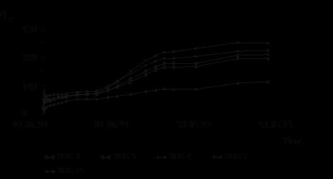
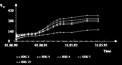
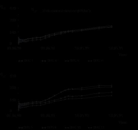


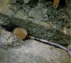
7 prof. Dr. Ing. Yasser El-Mossallamy 7 DG Bank, Frankfurt Measuring raft contact stresses Slide: 13 DG Bank, Frankfurt Measuring water pressure beneath the raft Slide: 14


8 prof. Dr. Ing. Yasser El-Mossallamy 8 DG Bank, Frankfurt Load-settlement behavior of piled raft, Load-time development a 0.6 L DG Bank Development of pile load share with time Time [days] Slide: 15 Instruments, Measuring room Slide: 16
9 Settlement [cm] Numerical analysis of piled raft Mathematical procedures Finite diference method (FDM) - One dimensional analysis (Load transfer method) - Two and three dimensional analysis Finite element method (FEM) - One dimensional analysis - Two dimensional analysis Plane strain Axisymmetry - Three dimensional analysis Boundary element method (BEM) - Using superposition technique - Complete boundary element structure Mixed technique - Hain and Lee (1978) - Hybrid model (O'Neill et al. 1981) - Modified hybrid model (Chow 1986) - El-Mossallamy (1996) Slide: 17 Comparison between observed and calculated behavior of piled raft L oad [MN] (a) (b) Observed behavior (b) E nd of construction Calculated, drained (a)1 year after end of construction a- Total load Calculated undrained Calculated, drained L oad [MN] Observed behavior L oad [MN] Calculated, drained Observed behavior b- Pile load share c- Raft load share Slide: 18 prof. Dr. Ing. Yasser El-Mossallamy 9
![Depth (m) Settlement [cm] Different load settlement relationships Load [MN] 0 4 8 12 16 20 0 (1) 4 (2) (4) 8 12 16 (3) 20 24 Legend (1) Single pile, (2) Average behaviorof the same pile as a member](/docs-images/74/70941216/images/10-1.jpg "of an equally loaded free standinggroup, (3) Average behaviorof the same pile as a member of the pile group below the raft of the DG Bank (piled raft foundation) (4) The observedaverage behaviorof")
10 Depth (m) Settlement [cm] Different load settlement relationships Load [MN] (1) 4 (2) (4) (3) Legend (1) Single pile, (2) Average behaviorof the same pile as a member of an equally loaded free standinggroup, (3) Average behaviorof the same pile as a member of the pile group below the raft of the DG Bank (piled raft foundation) (4) The observedaverage behaviorof the piled raft piles. Domain of measured pile loads Slide: 19 Development of pile skin friction by piled raft Skin friction (kn/m²) Normal force (MN) (1) (2) (1) Calculated (2) Observed (1) (2) Slide: 20 prof. Dr. Ing. Yasser El-Mossallamy 10
![Settlement [cm] Comparison between measured and calculated settlement Main Tower Side buildings 0 4 8 1 I I 12 16 2 20 3 Settlement joint Settlement joint Settlement trough along section I - I 1](/docs-images/74/70941216/images/11-0.jpg "Measurements, piled raft 2 Calculation, piled raft 3 Calculation, raft without piles Slide: 21 Main tower Side buildings Distribution of bending moments of the piled raft and of the corresponding")
11 Settlement [cm] Comparison between measured and calculated settlement Main Tower Side buildings I I Settlement joint Settlement joint Settlement trough along section I - I 1 Measurements, piled raft 2 Calculation, piled raft 3 Calculation, raft without piles Slide: 21 Main tower Side buildings Distribution of bending moments of the piled raft and of the corresponding raft without piles 1 2 Main tower Side buildings 1 2 Settlement joint Settlement jo Slide: 22 prof. Dr. Ing. Yasser El-Mossallamy 11
12 prof. Dr. Ing. Yasser El-Mossallamy 12 Contour lines of normalized vertical stresses beneath the center line of the piled raft and of the corresponding raft without piles Main Tower Side Building Main Tower Side Building Piled raft foundation Conventional raft foundation n n n = z o :Normalized vertical stresses z :Vertical stresses o :Average applied stresses of the main tower Settlement joint Slide: 23 Features of piled raft behavior: - Pile behavior depends on pile position - Pile capacity is completely difference than that of corresponding single pile - Skin friction develops from pile tip to pile top - Fewer number of piles can decrease the settlement significantly - Pile arrangement within pile group beneath the structural elements can reduce the raft internal stresses significantly. This has an effect on the reinforcement grad, on the raft thickness, on the required excavation depth, on the design of the required shoring system and on the required dewatering. Slide: 24


13 prof. Dr. Ing. Yasser El-Mossallamy 13 Application of piled raft in calcareous sand Foundation of High Rise Building (Kuwait) Salimia, El-Mossallamy et al. Slide: 25 Application of piled raft in calcareous sand Foundation of High Rise Building (Kuwait) Subsoil conditions Slide: 26


14 prof. Dr. Ing. Yasser El-Mossallamy 14 Application of piled raft in calcareous sand Foundation of High Rise Building (Kuwait) 624 piles with 0.9 m diameter 461 piles with 0.6 m diameter Pile length = 22 m Traditional deep foundation of the high-rise building Salimia, Kuwait Slide: 27 Behavior of calcareous sand Silica sand Calcareous sand Silica sand Calcareous sand Slide: 28
15 prof. Dr. Ing. Yasser El-Mossallamy 15 Application of piled raft in calcareous sand Foundation of High Rise Building (Kuwait) Results of pile load tests in Calcareous sand Slide: 29 Application of piled raft in calcareous sand Foundation of High Rise Building (Kuwait) 250 piles with 1.2 m diameter 146 piles with 0.6 m diameter Pile length = 17 m Proposal of an optimized piled raft for the high-rise building Salimia, Kuwait Slide: 30

 Traditional deep foundation Piled raft")


16 prof. Dr. Ing. Yasser El-Mossallamy 16 Application of piled raft in calcareous sand Foundation of High Rise Building (Kuwait) Traditional deep foundation Piled raft foundation Total no. piles Pile diameter 0.9 and and 0.6 Pile length 22 m 17 m Total length of piles m 6732 m Comparison between traditional piled foundation and piled raft foundation Slide: 31 Application of piled raft in difficult geological conditions Foundation of High Rise Building (Jabal Omar Complex Makkah, Saudi Arabia) Slide: 32

 Design")
 3- Unequal")
 Slide:")
17 prof. Dr. Ing. Yasser El-Mossallamy 17 Application of piled raft in difficult geological conditions Foundation of High Rise Building (Jabal Omar Complex Makkah, Saudi Arabia) Design aspects: 1- Foundation partially on soil, partially on rock 2- High earth pressure (30 m height) 3- Unequal earth pressure Slide: 33 Application of piled raft in difficult geological conditions Foundation of High Rise Building (Jabal Omar Complex Makkah, Saudi Arabia) Slide: 34
18 prof. Dr. Ing. Yasser El-Mossallamy m Plaxis 3D Foundation Case history: Japan Center m GW m a) Cross section 0.0 = 98.9 mnn Q T m m b) Plan Q = Quaternary Sand/Gravel T = Tertiary clay Slide: 35 Embedded piles Embedded piles: pile t skin F foot soil Slide: 36

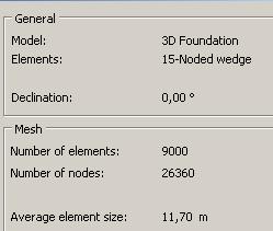
19 prof. Dr. Ing. Yasser El-Mossallamy 19 3D FE-Model Slide: 37 Loads Slide: 38


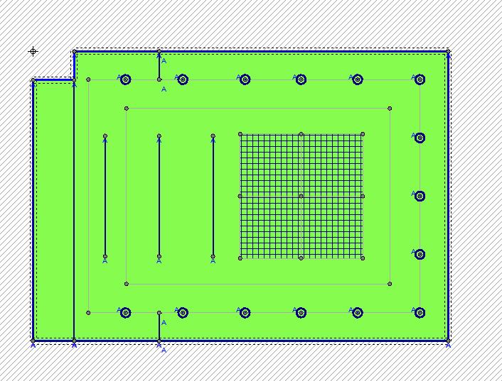
20 prof. Dr. Ing. Yasser El-Mossallamy 20 Loads Slide: 39 Graphical presentation of the piles in different working planes Slide: 40


21 Deviatoric stress ( prof. Dr. Ing. Yasser El-Mossallamy 21 3D FE-Model Slide: 41 Applied Constitutive Law 1500 FEM results Test results CD - Triaxial test = 400 KN/m² = 200 KN/m² 300 = 100 KN/m² 3 ( q a q f 1 E 50 Asymptote 1 E ur Failure line Axial strain Axial strain 1 Hardening soil model g / g = 20 / 10 kn/m³ ref E = 30 MN/m² w = 1,0 50 ref c = 40 kn/m² f = 29 = 0,0 E ur = 90 MN/m² nref= 0.2 R f = 0.9 Slide: 42

22 Settlement (cm) prof. Dr. Ing. Yasser El-Mossallamy 22 Soil parameters Table 1: Geotechnical parameters a- Hardening soil mode Soil parameter Filling Quaternary Sand/Gravel E ref 50 [MN/m2 ] ref E ur [MN/m 2 ] Overconsolid ated clay ur [-] m [-] R f [-] / [kn/m 3 ] 18/8 19/11 20/10 k x [m/sec] x 10-5 k y [m/sec] k x c [kn/m 2 ] [ ] K o [-] where: E ref 50 Primary loading stiffness ref E ur Unloading/reloading stiffness ur Unloading/reloading Poisson s ratio m Power in stiffness laws R f Failure ratio / Total / Effective unit weight of soil c Cohesion Angle of internal friction K o Coefficient of earth pressure at rest k x, k y Permeability coefficient in the horizontal and vertical direction b- Mohr-Coulomb model Soil parameter Limestone E [MN/m 2 ] 750 [-] 0.3 / [kn/m 3 ] 20/10 k x [m/sec] 10-3 k y [m/sec] 10-3 c [kn/m 2 ] 200 [ ] 35 Structure elements Piles: E concrete = MN/m² and = 0.2 Anchor tendons: E steel = MN/m² Slide: 43 Foundation settlement under working loads obs. 1 Slide: 44


23 prof. Dr. Ing. Yasser El-Mossallamy 23 Piled raft of Minaret Slide: 45 Geological conditions (Rock surface contour lines Slide: 46


24 prof. Dr. Ing. Yasser El-Mossallamy 24 Geological Sections Slide: 47 Finite element model Igneous rock Alluvium deposit Alluvium deposit Slide: 48


25 prof. Dr. Ing. Yasser El-Mossallamy 25 Foundation model Igneous rock Slide: 49 Page 49 Piled raft of Minaret Igneous rock Slide: 50


26 prof. Dr. Ing. Yasser El-Mossallamy 26 Raft Settlement Max. settlement = 37.1 mm Slide: 51 Raft Settlement Max. settlement = 37.1 mm Slide: 52


 Slide:")
27 prof. Dr. Ing. Yasser El-Mossallamy 27 Pile Stiffness (MN/m) Slide: 53 Page 53 Slide: 54


28 Embedded piles for large tanks on soft soil No. of piles = 376 Pile diameter = 1.5 m Tank cross section Slide: 55 Embedded piles for large tanks on soft soil Slide: 56 prof. Dr. Ing. Yasser El-Mossallamy 28


29 Embedded piles for large tanks on soft soil Slide: 57 Embedded piles for large tanks on soft soil INFOGRAPH Calculation - 3-dim. finite element analysis - Structural system modeled as an overall system - Dynamic analysis 0,600 a(t) 0,500 0,400 0,300 0,200 0,100 0, ,5 1 1,5 2 2,5 3 3,5 4 Slide: prof. Dr. Ing. Yasser El-Mossallamy 29

30 prof. Dr. Ing. Yasser El-Mossallamy 30 Embedded piles for large tanks on soft soil Slide: 59 Slide: 60
31 Structural engineers Geotechnical engineers Slide: 61 Design concept of piled rafts Lab testing (e.g. Triaxial tests) Field tests(e.g. SPT) Pile load test, Prototype Soil model Back-calculation Comparison Model Simulation soil-structure interaction Optimization analysis - economic conditions - serviceability requirements Foundation design Serviceability limit state Ultimate Limit state Determine the required structural parameter 1- pile stiffness depending on pile position 2- soil subgrade reaction modulus for the raft Structural design Slide: 62 prof. Dr. Ing. Yasser El-Mossallamy 31
 Total applied load (MN) 1000 800 6000 400 0 2000 0 1 2 3 End of basic construction Final construction 1.7.97 1.1.98 1.7.98 1.1.99 1.")

32 J I H G F E High shelves 0.5 m D müm Neighboring building müm Neighboring building C Foundation = müm 17.0 m 14.0 m Neckar Street Tower Kaiser Street B A G.S. = müm GW cal.= müm prof. Dr. Ing. Yasser El-Mossallamy 32 Settlement (cm) Total applied load (MN) End of basic construction Final construction Time Conclusion / Résumé Foundation on overconsolidated clay Foundation on medium to dense sand Side building Gallusanlage Piled raft foundation Section 8-8 Foundation on soft clay Foundation on heterogeneous subsoil, uncoupled piled raft Raft Middle plastic clay Piles High plastic clay Moraine Compacted soil Application of piled raft Slide: 63 Conclusion / Résumé Controlling the settlement Optimizing the foundation design Piled raft foundation Increasing the bearing capacity F a) Prandtl zone for complete free flow failure pile existence neglected Aim of piled raft F g t t slip line neglected Slide: 64 b) Assumed block failure with free flow at the pile base area


33 prof. Dr. Ing. Yasser El-Mossallamy 33 Slide: 65
PLAXIS 3D FOUNDATION Validation Manual. version 1.5
 PLAXIS 3D FOUNDATION Validation Manual version 1.5 TABLE OF CONTENTS TABLE OF CONTENTS 1 Introduction...1-1 2 Soil model problems with known theoretical solutions...2-1 2.1 Bi-axial test with linear elastic
1 Introduction. Abstract
 Abstract This paper presents a three-dimensional numerical model for analysing via finite element method (FEM) the mechanized tunneling in urban areas. The numerical model is meant to represent the typical
Theory of Shear Strength
 MAJ 1013 ADVANCED SOIL MECHANICS Theory of Shear Strength Prepared by, Dr. Hetty 1 Strength of different materials Steel Concrete Soil Tensile strength Compressive strength Shear strength Complex behavior
Theory of Shear Strength
 SKAA 1713 SOIL MECHANICS Theory of Shear Strength Prepared by, Dr. Hetty 1 SOIL STRENGTH DEFINITION Shear strength of a soil is the maximum internal resistance to applied shearing forces The maximum or
SOIL MODELS: SAFETY FACTORS AND SETTLEMENTS
 PERIODICA POLYTECHNICA SER. CIV. ENG. VOL. 48, NO. 1 2, PP. 53 63 (2004) SOIL MODELS: SAFETY FACTORS AND SETTLEMENTS Gabriella VARGA and Zoltán CZAP Geotechnical Department Budapest University of Technology
EN Eurocode 7. Section 3 Geotechnical Data Section 6 Spread Foundations. Trevor L.L. Orr Trinity College Dublin Ireland.
 EN 1997 1: Sections 3 and 6 Your logo Brussels, 18-20 February 2008 Dissemination of information workshop 1 EN 1997-1 Eurocode 7 Section 3 Geotechnical Data Section 6 Spread Foundations Trevor L.L. Orr
TC211 Workshop CALIBRATION OF RIGID INCLUSION PARAMETERS BASED ON. Jérôme Racinais. September 15, 2015 PRESSUMETER TEST RESULTS
 Jérôme Racinais September 15, 215 TC211 Workshop CALIBRATION OF RIGID INCLUSION PARAMETERS BASED ON PRESSUMETER TEST RESULTS Table of contents 1. Reminder about pressuremeter tests 2. General behaviour
Clayey sand (SC)
") Pile Bearing Capacity Analysis / Verification Input data Project Task : PROJECT: "NEW STEAM BOILER U-5190 Part : A-1 Descript. : The objective of this Analysis is the Pile allowable bearing Capacity Analysis
Pile Bearing Capacity Analysis / Verification Input data Project Task : PROJECT: "NEW STEAM BOILER U-5190 Part : A-1 Descript. : The objective of this Analysis is the Pile allowable bearing Capacity Analysis
Engineeringmanuals. Part2
 Engineeringmanuals Part2 Engineering manuals for GEO5 programs Part 2 Chapter 1-12, refer to Engineering Manual Part 1 Chapter 13. Pile Foundations Introduction... 2 Chapter 14. Analysis of vertical load-bearing
Numerical Investigation of the Effect of Recent Load History on the Behaviour of Steel Piles under Horizontal Loading
 Numerical Investigation of the Effect of Recent Load History on the Behaviour of Steel Piles under Horizontal Loading K. Abdel-Rahman Dr.-Ing., Institute of Soil Mechanics, Foundation Engineering and Waterpower
SOIL SHEAR STRENGTH. Prepared by: Dr. Hetty Muhammad Azril Fauziah Kassim Norafida
 SOIL SHEAR STRENGTH Prepared by: Dr. Hetty Muhammad Azril Fauziah Kassim Norafida What is shear strength Shear strength of a soil is the maximum internal resistance to applied shearing forces Why it is
INTI COLLEGE MALAYSIA
 EGC373 (F) / Page 1 of 5 INTI COLLEGE MALAYSIA UK DEGREE TRANSFER PROGRAMME INTI ADELAIDE TRANSFER PROGRAMME EGC 373: FOUNDATION ENGINEERING FINAL EXAMINATION : AUGUST 00 SESSION This paper consists of
Chapter (12) Instructor : Dr. Jehad Hamad
 Instructor : Dr. Jehad Hamad") Chapter (12) Instructor : Dr. Jehad Hamad 2017-2016 Chapter Outlines Shear strength in soils Direct shear test Unconfined Compression Test Tri-axial Test Shear Strength The strength of a material is the
Chapter (12) Instructor : Dr. Jehad Hamad 2017-2016 Chapter Outlines Shear strength in soils Direct shear test Unconfined Compression Test Tri-axial Test Shear Strength The strength of a material is the
Chapter 5 Shear Strength of Soil
 Page 5 Chapter 5 Shear Strength of Soil. The internal resistance per unit area that the soil mass can offer to resist failure and sliding along any plane inside it is called (a) strength (b) shear strength
Finite Element analysis of Laterally Loaded Piles on Sloping Ground
 Indian Geotechnical Journal, 41(3), 2011, 155-161 Technical Note Finite Element analysis of Laterally Loaded Piles on Sloping Ground K. Muthukkumaran 1 and N. Almas Begum 2 Key words Lateral load, finite
SHEAR STRENGTH OF SOIL
 Soil Failure Criteria SHEAR STRENGTH OF SOIL Knowledge about the shear strength of soil important for the analysis of: Bearing capacity of foundations, Slope stability, Lateral pressure on retaining structures,
Prof. Dr.-Ing. Martin Achmus Institute of Soil Mechanics, Foundation Engineering and Waterpower Engineering. Monopile design
 Prof. Dr.-Ing. Martin Achmus Institute of Soil Mechanics, Foundation Engineering and Waterpower Engineering Monopile design Addis Ababa, September 2010 Monopile design Presentation structure: Design proofs
Monitoring of underground construction
 Monitoring of underground construction Geotechnical Aspects of Underground Construction in Soft Ground Yoo, Park, Kim & Ban (Eds) 2014 Korean Geotechnical Society, Seoul, Korea, ISBN 978-1-138-02700-8
Chapter (11) Pile Foundations
 Pile Foundations") Chapter (11) Introduction Piles are structural members that are made of steel, concrete, or timber. They are used to build pile foundations (classified as deep foundations) which cost more than shallow
Chapter (11) Introduction Piles are structural members that are made of steel, concrete, or timber. They are used to build pile foundations (classified as deep foundations) which cost more than shallow
PILE-SUPPORTED RAFT FOUNDATION SYSTEM
 PILE-SUPPORTED RAFT FOUNDATION SYSTEM Emre Biringen, Bechtel Power Corporation, Frederick, Maryland, USA Mohab Sabry, Bechtel Power Corporation, Frederick, Maryland, USA Over the past decades, there has
Towards Efficient Finite Element Model Review Dr. Richard Witasse, Plaxis bv (based on the original presentation of Dr.
 Towards Efficient Finite Element Model Review Dr. Richard Witasse, Plaxis bv (based on the original presentation of Dr. Brinkgreve) Journée Technique du CFMS, 16 Mars 2011, Paris 1/32 Topics FEA in geotechnical
Seismic Response Analysis of Structure Supported by Piles Subjected to Very Large Earthquake Based on 3D-FEM
 Seismic Response Analysis of Structure Supported by Piles Subjected to Very Large Earthquake Based on 3D-FEM *Hisatoshi Kashiwa 1) and Yuji Miyamoto 2) 1), 2) Dept. of Architectural Engineering Division
Cyclic lateral response of piles in dry sand: Effect of pile slenderness
 Cyclic lateral response of piles in dry sand: Effect of pile slenderness Rafa S. 1, Rouaz I. 1,Bouaicha A. 1, Abed El Hamid A. 1 Rafa.sidali@gmail.com 1 National Center for Studies and Integrated Researches
Seabed instability and 3D FE jack-up soil-structure interaction analysis
 Seabed instability and 3D FE jack-up soil-structure interaction analysis Lindita Kellezi, GEO Danish Geotechnical Institute, Denmark Gregers Kudsk, Maersk Contractors, Denmark Hugo Hofstede, Marine Structure
TIME-DEPENDENT BEHAVIOR OF PILE UNDER LATERAL LOAD USING THE BOUNDING SURFACE MODEL
 TIME-DEPENDENT BEHAVIOR OF PILE UNDER LATERAL LOAD USING THE BOUNDING SURFACE MODEL Qassun S. Mohammed Shafiqu and Maarib M. Ahmed Al-Sammaraey Department of Civil Engineering, Nahrain University, Iraq
Reinforced Soil Structures Reinforced Soil Walls. Prof K. Rajagopal Department of Civil Engineering IIT Madras, Chennai
 Geosynthetics and Reinforced Soil Structures Reinforced Soil Walls continued Prof K. Rajagopal Department of Civil Engineering IIT Madras, Chennai e-mail: gopalkr@iitm.ac.inac in Outline of the Lecture
Analysis of the horizontal bearing capacity of a single pile
 Engineering manual No. 16 Updated: 07/2018 Analysis of the horizontal bearing capacity of a single pile Program: Soubor: Pile Demo_manual_16.gpi The objective of this engineering manual is to explain how
Laboratory Testing Total & Effective Stress Analysis
 SKAA 1713 SOIL MECHANICS Laboratory Testing Total & Effective Stress Analysis Prepared by: Dr. Hetty Mohr Coulomb failure criterion with Mohr circle of stress 2 ' 2 ' ' ' 3 ' 1 ' 3 ' 1 Cot Sin c ' ' 2
CHAPTER 8 CALCULATION THEORY
 CHAPTER 8 CALCULATION THEORY. Volume 2 CHAPTER 8 CALCULATION THEORY Detailed in this chapter: the theories behind the program the equations and methods that are use to perform the analyses. CONTENTS CHAPTER
Ch 4a Stress, Strain and Shearing
 Ch. 4a - Stress, Strain, Shearing Page 1 Ch 4a Stress, Strain and Shearing Reading Assignment Ch. 4a Lecture Notes Sections 4.1-4.3 (Salgado) Other Materials Handout 4 Homework Assignment 3 Problems 4-13,
SHEAR STRENGTH OF SOIL
 SHEAR STRENGTH OF SOIL Necessity of studying Shear Strength of soils : Soil failure usually occurs in the form of shearing along internal surface within the soil. Shear Strength: Thus, structural strength
TABLE OF CONTENTS CHAPTER TITLE PAGE TITLE PAGE DECLARATION DEDIDATION ACKNOWLEDGEMENTS ABSTRACT ABSTRAK
 TABLE OF CONTENTS CHAPTER TITLE PAGE TITLE PAGE DECLARATION DEDIDATION ACKNOWLEDGEMENTS ABSTRACT ABSTRAK TABLE OF CONTENTS LIST OF TABLE LIST OF FIGURES LIST OF SYMBOLS LIST OF APENDICES i ii iii iv v
A Constitutive Framework for the Numerical Analysis of Organic Soils and Directionally Dependent Materials
 Dublin, October 2010 A Constitutive Framework for the Numerical Analysis of Organic Soils and Directionally Dependent Materials FracMan Technology Group Dr Mark Cottrell Presentation Outline Some Physical
ANALYSIS OF LATERALLY LOADED FIXED HEADED SINGLE FLOATING PILE IN MULTILAYERED SOIL USING BEF APPROACH
 INDIAN GEOTECHNICAL SOCIETY, KOLKATA CHAPTER GEOTECHNICS FOR INFRASTRUCTURE DEVELOPMENT KOLKATA 11 th 12 th March 2016, Kolkata, West Bengal, India ANALYSIS OF LATERALLY LOADED FIXED HEADED SINGLE FLOATING
THE STRUCTURAL DESIGN OF PILE FOUNDATIONS BASED ON LRFD FOR JAPANESE HIGHWAYS
 THE STRUCTURAL DESIGN OF PILE FOUNDATIONS BASED ON LRFD FOR JAPANESE HIGHWAYS Hideaki Nishida 1,Toshiaki Nanazawa 2, Masahiro Shirato 3, Tetsuya Kohno 4, and Mitsuaki Kitaura 5 Abstract One of the motivations
Table 3. Empirical Coefficients for BS 8002 equation. A (degrees) Rounded Sub-angular. 2 Angular. B (degrees) Uniform Moderate grading.
 Rounded Sub-angular. 2 Angular. B (degrees) Uniform Moderate grading.") Hatanaka and Uchida (1996); ' 20N 20 12N 20 ' 45 A lower bound for the above equation is given as; 12N 15 ' 45 Table 3. Empirical Coefficients for BS 8002 equation A Angularity 1) A (degrees) Rounded 0
Hatanaka and Uchida (1996); ' 20N 20 12N 20 ' 45 A lower bound for the above equation is given as; 12N 15 ' 45 Table 3. Empirical Coefficients for BS 8002 equation A Angularity 1) A (degrees) Rounded 0
PARAMETRIC STUDY OF PILED-RAFT FOUNDATION IN DEEP EXCAVATION OF TAIPEI METROPOLITAN
 58 Journal of Marine Science and Technology, Vol. 5, No. 5, pp. 58-519 (17) DOI: 1.119/JMST-17-18-3 PARAMETRIC STUDY OF PILED-RAFT FOUNDATION IN DEEP EXCAVATION OF TAIPEI METROPOLITAN Der-Guey Lin 1, Wei-Hsiang
(Refer Slide Time: 02:18)
") Geology and Soil Mechanics Prof. P. Ghosh Department of Civil Engineering Indian Institute of Technology Kanpur Lecture 40 Shear Strength of Soil - C Keywords: Shear strength of soil, direct shear test,
Geology and Soil Mechanics Prof. P. Ghosh Department of Civil Engineering Indian Institute of Technology Kanpur Lecture 40 Shear Strength of Soil - C Keywords: Shear strength of soil, direct shear test,
NEW DOWN-HOLE PENETROMETER (DHP-CIGMAT) FOR CONSTRUCTION APPLICATIONS
 FOR CONSTRUCTION APPLICATIONS") NEW DOWN-HOLE PENETROMETER (DHP-CIGMAT) FOR CONSTRUCTION APPLICATIONS 1 2 C. Vipulanandan 1, Ph.D., M. ASCE and Omer F. Usluogullari 2 Chairman, Professor, Director of Center for Innovative Grouting Materials
NEW DOWN-HOLE PENETROMETER (DHP-CIGMAT) FOR CONSTRUCTION APPLICATIONS 1 2 C. Vipulanandan 1, Ph.D., M. ASCE and Omer F. Usluogullari 2 Chairman, Professor, Director of Center for Innovative Grouting Materials
Cavity Expansion Methods in Geomechanics
 Cavity Expansion Methods in Geomechanics by Hai-Sui Yu School of Civil Engineering, University of Nottingham, U. K. KLUWER ACADEMIC PUBLISHERS DORDRECHT / BOSTON / LONDON TABLE OF CONTENTS Foreword Preface
Verification of a Micropile Foundation
 Engineering manual No. 36 Update 02/2018 Verification of a Micropile Foundation Program: File: Pile Group Demo_manual_en_36.gsp The objective of this engineering manual is to explain the application of
Simulation of footings under inclined loads using different constitutive models
 Simulation of footings under inclined loads using different constitutive models J. Hintner, P.A. Vermeer Institute of Geotechnical Engineering, University of Stuttgart, Germany P.-A. von Wolffersdorff
Deep Foundations 2. Load Capacity of a Single Pile
 Deep Foundations 2 Load Capacity of a Single Pile All calculations of pile capacity are approximate because it is almost impossible to account for the variability of soil types and the differences in the
EXTENDED ABSTRACT. Combined Pile Raft Foundation
 EXTENDED ABSTRACT Combined Pile Raft Foundation Rui Diogo Gomes da Silva Supervisor: Prof. Jaime Alberto dos Santos December 2009 1. Introduction The piled raft foundation is an innovative design concept
Validation of empirical formulas to derive model parameters for sands
 Validation of empirical formulas to derive model parameters for sands R.B.J. Brinkgreve Geo-Engineering Section, Delft University of Technology, Delft, Netherlands/Plaxis B.V., Delft, Netherlands E. Engin
The Hardening Soil model with small strian stiffness
 The Hardening Soil model with small strain stiffness in Zsoil v2011 Rafal OBRZUD GeoMod Ing. SA, Lausanne Content Introduction Framework of the Hardening Soil model Hardening Soil SmallStrain Hardening
Landslide FE Stability Analysis
 Landslide FE Stability Analysis L. Kellezi Dept. of Geotechnical Engineering, GEO-Danish Geotechnical Institute, Denmark S. Allkja Altea & Geostudio 2000, Albania P. B. Hansen Dept. of Geotechnical Engineering,
Behavior of Offshore Piles under Monotonic Inclined Pullout Loading
 Behavior of Offshore Piles under Monotonic Inclined Pullout Loading Mohamed I. Ramadan Lecturer, Civil Engineering Department, Faculty of Engineering, Assiut University, Assiut, Egypt, mihr81@gmail.com
Introduction to Soil Mechanics
 Introduction to Soil Mechanics Sela Sode and Colin Jones WILEY Blackwell Contents Preface Dedication and Acknowledgments List of Symbols Soil Structure 1.1 Volume relationships 1.1.1 Voids ratio (e) 1.1.2
Shear strength. Common cases of shearing In practice, the state of stress in the ground will be complex. Common cases of shearing Strength
 Shear strength Common cases of shearing Strength Near any geotechnical construction (e.g. slopes, excavations, tunnels and foundations) there will be both mean and normal stresses and shear stresses. The
Effect of embedment depth and stress anisotropy on expansion and contraction of cylindrical cavities
 Effect of embedment depth and stress anisotropy on expansion and contraction of cylindrical cavities Hany El Naggar, Ph.D., P. Eng. and M. Hesham El Naggar, Ph.D., P. Eng. Department of Civil Engineering
INTRODUCTION TO STATIC ANALYSIS PDPI 2013
 INTRODUCTION TO STATIC ANALYSIS PDPI 2013 What is Pile Capacity? When we load a pile until IT Fails what is IT Strength Considerations Two Failure Modes 1. Pile structural failure controlled by allowable
Finite Element Investigation of the Interaction between a Pile and a Soft Soil focussing on Negative Skin Friction
 NGM 2016 Reykjavik Proceedings of the 17 th Nordic Geotechnical Meeting Challenges in Nordic Geotechnic 25 th 28 th of May Finite Element Investigation of the Interaction between a Pile and a Soft Soil
2D Liquefaction Analysis for Bridge Abutment
 D Liquefaction Analysis for Bridge Abutment Tutorial by Angel Francisco Martinez Integrated Solver Optimized for the next generation 64-bit platform Finite Element Solutions for Geotechnical Engineering
vulcanhammer.net This document downloaded from
 This document downloaded from vulcanhammer.net since 1997, your source for engineering information for the deep foundation and marine construction industries, and the historical site for Vulcan Iron Works
Geotechnical Properties of Soil
 Geotechnical Properties of Soil 1 Soil Texture Particle size, shape and size distribution Coarse-textured (Gravel, Sand) Fine-textured (Silt, Clay) Visibility by the naked eye (0.05 mm is the approximate
D1. A normally consolidated clay has the following void ratio e versus effective stress σ relationship obtained in an oedometer test.
 (d) COMPRESSIBILITY AND CONSOLIDATION D1. A normally consolidated clay has the following void ratio e versus effective stress σ relationship obtained in an oedometer test. (a) Plot the e - σ curve. (b)
NUMERICAL VERIFICATION OF GEOTECHNICAL STRUCTURE IN UNFAVOURABLE GEOLOGICAL CONDITIONS CASE STUDY
 NUMERICAL VERIFICATION OF GEOTECHNICAL STRUCTURE IN UNFAVOURABLE GEOLOGICAL CONDITIONS CASE STUDY Abstract Marián DRUSA Department of Geotechnics, Faculty of Civil Engineering, Univerzity of Žilina, Univerzitná
Table of Contents Chapter 1 Introduction to Geotechnical Engineering 1.1 Geotechnical Engineering 1.2 The Unique Nature of Soil and Rock Materials
 Table of Contents Chapter 1 Introduction to Geotechnical Engineering 1.1 Geotechnical Engineering 1.2 The Unique Nature of Soil and Rock Materials 1.3 Scope of This Book 1.4 Historical Development of Geotechnical
2D and 3D Numerical Simulation of Load-Settlement Behaviour of Axially Loaded Pile Foundations
 American Journal of Civil Engineering and Architecture, 2017, Vol. 5, No. 5, 187-195 Available online at http://pubs.sciepub.com/ajcea/5/5/2 Science and Education Publishing DOI:10.12691/ajcea-5-5-2 2D
Advanced model for soft soils. Modified Cam-Clay (MCC)
") Advanced model for soft soils. Modified Cam-Clay (MCC) c ZACE Services Ltd August 2011 1 / 62 2 / 62 MCC: Yield surface F (σ,p c ) = q 2 + M 2 c r 2 (θ) p (p p c ) = 0 Compression meridian Θ = +π/6 -σ
Advanced model for soft soils. Modified Cam-Clay (MCC) c ZACE Services Ltd August 2011 1 / 62 2 / 62 MCC: Yield surface F (σ,p c ) = q 2 + M 2 c r 2 (θ) p (p p c ) = 0 Compression meridian Θ = +π/6 -σ
SOIL MECHANICS: palgrave. Principles and Practice. Graham Barnes. macmiiian THIRD EDITION
 SOIL MECHANICS: Principles and Practice THIRD EDITION Graham Barnes palgrave macmiiian 'running Contents Preface xii Fine soil 19 List of symbols xiv Mass structure 21 Note on units xix Degree of weathering
Influence of Soil Models on Numerical Simulation of Geotechnical works in Bangkok subsoil
 Influence of Soil Models on Numerical Simulation of Geotechnical works in Bangkok subsoil Tanapong Rukdeechuai, Pornkasem Jongpradist, Anucha Wonglert, Theerapong Kaewsri Department of Civil Engineering,
8.1. What is meant by the shear strength of soils? Solution 8.1 Shear strength of a soil is its internal resistance to shearing stresses.
 8.1. What is meant by the shear strength of soils? Solution 8.1 Shear strength of a soil is its internal resistance to shearing stresses. 8.2. Some soils show a peak shear strength. Why and what type(s)
(C) Global Journal of Engineering Science and Research Management
 Global Journal of Engineering Science and Research Management") GEOTECHNCIAL ASSESSMENT OF PART OF PORT HARCOURT, NIGER DELTA FOR STRUCTURAL ANALYSIS Warmate Tamunonengiyeofori Geostrat International Services Limited, www.geostratinternational.com. *Correspondence
GEOTECHNCIAL ASSESSMENT OF PART OF PORT HARCOURT, NIGER DELTA FOR STRUCTURAL ANALYSIS Warmate Tamunonengiyeofori Geostrat International Services Limited, www.geostratinternational.com. *Correspondence
3-BEARING CAPACITY OF SOILS
 3-BEARING CAPACITY OF SOILS INTRODUCTION The soil must be capable of carrying the loads from any engineered structure placed upon it without a shear failure and with the resulting settlements being tolerable
International Journal of Advance Engineering and Research Development. Parametric Study of Beam Slab Raft Foundation
 Scientific Journal of Impact Factor (SJIF): 4.72 International Journal of Advance Engineering and Research Development Volume 4, Issue, May-2017 Parametric Study of Beam Slab Raft Foundation Sudhir.D.Ravani
Numerical modelling of tension piles
 Numerical modelling of tension piles S. van Baars Ministry of Public Works, Utrecht, Netherlands W.J. van Niekerk Ballast Nedam Engineering, Amstelveen, Netherlands Keywords: tension piles, shaft friction,
RELIABILITY ASPECTS OF DESIGN OF COMBINED PILED-RAFT FOUNDATIONS (CPRF)
") 2nd Int. PhD Symposium in Civil Engineering 1998 Budapest RELIABILITY ASPECTS OF DESIGN OF COMBINED PILED-RAFT FOUNDATIONS (CPRF) Carsten Ahner 1, Dmitri Soukhov 2, Gert König 3 University of Leipzig,
2nd Int. PhD Symposium in Civil Engineering 1998 Budapest RELIABILITY ASPECTS OF DESIGN OF COMBINED PILED-RAFT FOUNDATIONS (CPRF) Carsten Ahner 1, Dmitri Soukhov 2, Gert König 3 University of Leipzig,
The Bearing Capacity of Soils. Dr Omar Al Hattamleh
 The Bearing Capacity of Soils Dr Omar Al Hattamleh Example of Bearing Capacity Failure Omar Play the move of bearing Capacity failure The Philippine one Transcona Grain Silos Failure - Canada The Bearing
Modelling of Earth Pressure from nearby Strip Footings on a Free & Anchored Sheet Pile Wall
 NGM 2016 Reykjavik Proceedings of the 17 th Nordic Geotechnical Meeting Challenges in Nordic Geotechnic 25 th 28 th of May Modelling of Earth Pressure from nearby Strip Footings on a Free & Anchored Sheet
Pile-clayey soil interaction analysis by boundary element method
 Journal of Rock Mechanics and Geotechnical Engineering. 12, 4 (1): 28 43 Pile-clayey soil interaction analysis by boundary element method Mohammed Y. Fattah 1, Kais T. Shlash 1, Madhat S. M. Al-Soud 2
Harmonized European standards for construction in Egypt
 Harmonized European standards for construction in Egypt EN 1998 - Design of structures for earthquake resistance Jean-Armand Calgaro Chairman of CEN/TC250 Organised with the support of the Egyptian Organization
Deformation And Stability Analysis Of A Cut Slope
 Deformation And Stability Analysis Of A Cut Slope Masyitah Binti Md Nujid 1 1 Faculty of Civil Engineering, University of Technology MARA (Perlis), 02600 Arau PERLIS e-mail:masyitahmn@perlis.uitm.edu.my
GEO E1050 Finite Element Method Mohr-Coulomb and other constitutive models. Wojciech Sołowski
 GEO E050 Finite Element Method Mohr-Coulomb and other constitutive models Wojciech Sołowski To learn today. Reminder elasticity 2. Elastic perfectly plastic theory: concept 3. Specific elastic-perfectly
water proofing will relatively long time fully completed) be provided 10 storey building (15x25m) original GWT position 1 sat = 20 kn/m 3
 be provided 10 storey building (15x25m) original GWT position 1 sat = 20 kn/m 3") P1 Question: An excavation will be made for a ten storey 15x25 m building. Temporary support of earth pressure and water pressure will be made by deep secant cantilever pile wall. The gross pressure due
P1 Question: An excavation will be made for a ten storey 15x25 m building. Temporary support of earth pressure and water pressure will be made by deep secant cantilever pile wall. The gross pressure due
Verification Manual GT
 Verification Manual GT Written by: The SoilVision Systems Ltd. Team Last Updated: Tuesday, February 20, 2018 SoilVision Systems Ltd. Saskatoon, Saskatchewan, Canada Software License The software described
Soils. Technical English - I 10 th week
 Technical English - I 10 th week Soils Soil Mechanics is defined as the branch of engineering science which enables an engineer to know theoretically or experimentally the behavior of soil under the action
ADVANCED SOIL MECHANICS FINAL EXAM (TAKE HOME):DUE THURSDAY, DECEMBER 19, 6PM.
:DUE THURSDAY, DECEMBER 19, 6PM.") 14.531 ADVANCED SOIL MECHANICS FINAL EXAM (TAKE HOME):DUE THURSDAY, DECEMBER 19, 2013 @ 6PM. Problem #1. Field load tests on strip footings yielded the test data provided below in Figure 1 and Table 1
14.531 ADVANCED SOIL MECHANICS FINAL EXAM (TAKE HOME):DUE THURSDAY, DECEMBER 19, 2013 @ 6PM. Problem #1. Field load tests on strip footings yielded the test data provided below in Figure 1 and Table 1
Analysis and measurements of settlement for heavy loaded rigid footing
 Analysis and measurements of settlement for heavy loaded rigid footing I. Sokoli University of Zagreb, Faculty of Civil Engineering, Ka i eva 26, 1 Zagreb, Croatia T. Ivši University of Zagreb, Faculty
UPLIFT CAPACITY OF PILES SUBJECTED TO INCLINED LOAD IN TWO LAYERED SOIL. Dr. Sunil S. Pusadkar 1, Sachin Ghormode 2 ABSTRACT
 50 th IGC 50 th INDIAN GEOTECHNICAL CONFERENCE 17 th 19 th DECEMBER 2015, Pune, Maharashtra, India Venue: College of Engineering (Estd. 1854), Pune, India UPLIFT CAPACITY OF PILES SUBJECTED TO INCLINED
Axially Loaded Piles
 Axially Loaded Piles 1 t- Curve Method using Finite Element Analysis The stress-strain relationship for an axially loaded pile can be described through three loading mechanisms: axial deformation in the
DYNAMIC ANALYSIS OF PILES IN SAND BASED ON SOIL-PILE INTERACTION
 October 1-17,, Beijing, China DYNAMIC ANALYSIS OF PILES IN SAND BASED ON SOIL-PILE INTERACTION Mohammad M. Ahmadi 1 and Mahdi Ehsani 1 Assistant Professor, Dept. of Civil Engineering, Geotechnical Group,
Triaxial Shear Test. o The most reliable method now available for determination of shear strength parameters.
 TOPICS Introduction Components of Shear Strength of Soils Normal and Shear Stresses on a Plane Mohr-Coulomb Failure Criterion Laboratory Shear Strength Testing Direct Shear Test Triaxial Compression Test
1.5 STRESS-PATH METHOD OF SETTLEMENT CALCULATION 1.5 STRESS-PATH METHOD OF SETTLEMENT CALCULATION
 Module 6 Lecture 40 Evaluation of Soil Settlement - 6 Topics 1.5 STRESS-PATH METHOD OF SETTLEMENT CALCULATION 1.5.1 Definition of Stress Path 1.5. Stress and Strain Path for Consolidated Undrained Undrained
WIND TUNNEL TESTING GEOTECHNICAL STUDY
 WIND TUNNEL TESTING Wind tunnel testing was conducted by the Boundary Layer Wind Tunnel Laboratory (BLWTL) at the University of Western Ontario (UWO) to develop wind load time histories for the chimney.
Module 4 Lecture 20 Pore water pressure and shear strength - 4 Topics
 Module 4 Lecture 20 Pore water pressure and shear strength - 4 Topics 1.2.6 Curvature of the Failure Envelope Effect of angularity of soil particles Effect of rate of loading during the test 1.2.7 Shear
PLAXIS. Material Models Manual
 PLAXIS Material Models Manual 2015 Build 7519 TABLE OF CONTENTS TABLE OF CONTENTS 1 Introduction 7 1.1 On the use of different models 7 1.2 Limitations 9 2 Preliminaries on material modelling 13 2.1 General
Evaluation of short piles bearing capacity subjected to lateral loading in sandy soil
 Evaluation of short piles bearing capacity subjected to lateral loading in sandy soil [Jafar Bolouri Bazaz, Javad Keshavarz] Abstract Almost all types of piles are subjected to lateral loads. In many cases,
Analysis of Pile Foundation Subjected to Lateral and Vertical Loads
 Analysis of Pile Foundation Subjected to Lateral and Vertical Loads Thadapaneni Kanakeswararao 1, B.Ganesh 2 1,2 Department of soil mechanics and foundation engg, Lenora college of Engineering and technology,
BRASIL MAY 2010
 ISSMGE TC - 17 221 BRASIL 22-23 MAY 2010 Symposium on New Techniques for Design and Construction in Soft Clays. Vacuum consolidation The environmental friendly consolidation of very soft poluted mud at
YOUR HW MUST BE STAPLED YOU MUST USE A PENCIL (no pens)
") Spring 2008 CIVE 462 HOMEWORK #1 1. Print out the syllabus. Read it. Write the grade percentages in the first page of your notes. 2. Go back to your 301 notes, internet, etc. and find the engineering definition
Spring 2008 CIVE 462 HOMEWORK #1 1. Print out the syllabus. Read it. Write the grade percentages in the first page of your notes. 2. Go back to your 301 notes, internet, etc. and find the engineering definition
Gapping effects on the lateral stiffness of piles in cohesive soil
 Gapping effects on the lateral stiffness of piles in cohesive soil Satyawan Pranjoto Engineering Geology, Auckland, New Zealand. M. J. Pender Department of Civil and Environmental Engineering, University
Shear Strength of Soils
 Shear Strength of Soils Soil strength Most of problems in soil engineering (foundations, slopes, etc.) soil withstands shear stresses. Shear strength of a soil is defined as the capacity to resist shear
Influences of material dilatancy and pore water pressure on stability factor of shallow tunnels
 Influences of material dilatancy and pore water pressure on stability factor of shallow tunnels YANG Xiao-li( ), HUANG Fu( ) School of Civil and Architectural Engineering, Central South University, Changsha
Examples to verify and illustrate ELPLA
 Determining contact pressures, settlements, moments and shear forces of slab foundations by the method of finite elements Version 2010 Program authors: M. El Gendy A. El Gendy GEOTEC: GEOTEC Software Inc.
Chapter (6) Geometric Design of Shallow Foundations
 Geometric Design of Shallow Foundations") Chapter (6) Geometric Design of Shallow Foundations Introduction As we stated in Chapter 3, foundations are considered to be shallow if if [D (3 4)B]. Shallow foundations have several advantages: minimum
Chapter (6) Geometric Design of Shallow Foundations Introduction As we stated in Chapter 3, foundations are considered to be shallow if if [D (3 4)B]. Shallow foundations have several advantages: minimum
HKIE-GD Workshop on Foundation Engineering 7 May Shallow Foundations. Dr Limin Zhang Hong Kong University of Science and Technology
 HKIE-GD Workshop on Foundation Engineering 7 May 2011 Shallow Foundations Dr Limin Zhang Hong Kong University of Science and Technology 1 Outline Summary of design requirements Load eccentricity Bearing
Dynamics Manual. Version 7
 Dynamics Manual Version 7 DYNAMICS MANUAL TABLE OF CONTENTS 1 Introduction...1-1 1.1 About this manual...1-1 2 Tutorial...2-1 2.1 Dynamic analysis of a generator on an elastic foundation...2-1 2.1.1 Input...2-1
Introduction to Geotechnical Engineering. ground
 Introduction to Geotechnical Engineering ground 1 Typical Geotechnical Project Geo-Laboratory ~ for testing soil properties Design Office ~ for design & analysis construction site 2 Shallow Foundations