Abstract The capability (P-Q) curve of generator can be determined only on the base of examinations in the power plant, i.e. on the base of: the no-lo
|
|
|
- Stuart Bridges
- 6 years ago
- Views:
Transcription
1 CONSTRUCTION OF GENERATOR CAPABILITY CURVES USING THE NEW METHOD FOR DETERMINATION OF POTIER REACTANCE M.M. Kostić*, M. Ivanović*, B. Kostić*, S. Ilić** and D. Ćirić** Electrical Engineering Institute Nikola Tesla, Belgrade, SERBIA* TPPs-OCMs "Kostolac", Kostolac, SERBIA **
2 Abstract The capability (P-Q) curve of generator can be determined only on the base of examinations in the power plant, i.e. on the base of: the no-load test, i. e. i fl (e l ) dependence, and the reactive load test, i.e. characteristic points A i (i f, u) The Potier reactance (X P )forthe points of the relevant values of reactive loads are determined, and then the capability (P G -Q G ) curve of the generator is being constructed. This method is verified for experimental regimes of active and reactive power around the nominal values, on the example of turbo generator 348 MW in power plant "Kostolac B". The significant deviation in relation to the P-Q curve of the drive manufacturer's documentation generator were established, and it is recommended d to update P-Q curves every 5-6 years or after major repairs. Similar deviations of P-Q curves were observed during the extensive testing and research for newer generators in U.S.
3 Introduction Capability curves, P G -Q G curves, Figure 1, are necessary to the operating stuff. The most important part of the curve is the part with coordinates (Q G Q G,N, P G P G,N ) which defines the generator regime with increased reactive power. Significant deviations of capability curves, compared to manufacturers, were obtained during the extensive testing and research for generators in U.S. (Figure 1).


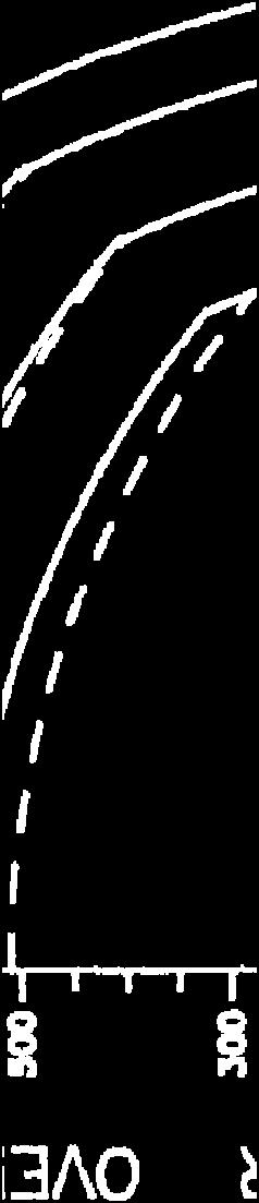


4 Introduction Figure 1: Comparison chart of actual capability (P-Q) curves with the manufacturers' generator capability curves


 and (q n) powers")


5 BASIC PRINCIPLES FOR THE DESIGN OF CAPABILITY CURVE Capability ity curve of generator e with unsaturated sauaed magnetic cc circuit cu Generator is sized to reach the nominal temperature at the rated values of (p n) and (q n) powers (the point R) i.e.: for induct currents, i a = i an = Const., φ φ n, and curve i f = Const.. and φ > φ n, i.e., q q R, with a reduced active power p p R Figure 2: Vector diagram of generator electromotive forces and the excitation currents (with corresponding scaling ratio)
 It is particularly difficult to quantify additional magnetic saturation on the part of the rotor of loaded d machine, i.e.. i fl = f(e l ).")
.")
6 BASIC PRINCIPLES FOR THE DESIGN OF CAPABILITY CURVE Vector diagrams of excitation currents of saturated machine The curve of saturated machine, derived from no-load test, i f0 (e) It is particularly difficult to quantify additional magnetic saturation on the part of the rotor of loaded d machine, i.e.. i fl = f(e l ). Influence of additional saturation of the rotor magnetic circuit is taken into account by introduction of Potier reactance (x P >x l, x l is stator leakage reactance) which h results in increased EMF( (e P = u+x P i > u+x+ l i = e l ). Figure 3: Magnetization curves i f0 (e) and i fl (e l ); diagrams of excitation currents: i fa,n = x d -x P and i fr fr =i fp +i fa,n

 beginning point C uns goes down for Δi")


7 BASIC PRINCIPLES FOR THE DESIGN OF CAPABILITY CURVE Capability ity curve of generator e with saturated a magnetic circuit cu The increase part of saturation current Δi f (e P ) = Δi fu + Δi fs+ Δi fr (Figure 3) beginning point C uns goes down for Δi f (e P ) (C R,C 1,C 2 and C M ) the corresponding arches i fi =Const Const. are moved down as well. Thus, for pure reactive load (p = 0), instead of point q' M, point q M < q' M is obtained q' M - reactive load maximum for generator with saturated magnetic circuit. Figure 4: Diagrams of electromotive forces and excitation currents for generator with saturated magnetic circuit
8 DETERMINATION OF GENERATORS POTIER REACTANCE Potier reactance is not constant in given range of voltage and load. It is necessary to determine the Potier reactance dependence x P (u,q): for accurate calculations and capability curve construction. Determination of Potier reactance for relevant (reactive) loads: xp( p (P Gi,Q Gi ) xp(q p Gcosφ=0 G,cosφ=0 ),, for Q Gi = Q Gcosφ=0 G,cosφ=0 since U G (P Gi, Q Gi ) U G (Q G,cosφ=0 φ ),, for Q Gi = Q G,cosφ=0 φ and x p =f(q G,U G ) f(q G ) For rated regime (P Gn, Q Gn, U n ): x P,n x P90, for i 90 =i an sinφ n. (1) In general case (P G, Q G, U): x P x P90, for i 90 =i a sinφ. (2)
9 DETERMINATION OF GENERATORS POTIER REACTANCE The obtained values (dependences) of Potier reactance x p =f(q G,U G ) f(q G,cosφ=0 ) should be used for design of generator capability curve. The specified rule was verified on the example of generator GTHW360 (360 MW) for regimes around the nominal (P G P Gn and Q G Q Gn ), )iebycomparisonof: i.e. of: measured values (I f,meas), and calculated values (I f,calc ), on the basis of Potier reactances (x P ) for Q G,cosφ=0 And, it is obtained I f,calc =I f,meas ±0.4% G,cosφ=0 Q Gn.
10 DETERMINATION OF GENERATORS POTIER REACTANCE In Figure 5 is given a dependence of Potier reactance, ce, x p,i pi (Q G ), for generator GTH-360 The Potier reactance (x p ), is changing when reactive power changes. These values decrease with increase in load, but Potier reactance value is greater then leakage reactance, x p,min x l Figure 5: Dependence of Potier reactance from reactive power, x pi ( x pi (Q G ), and x l = > x pmin pi (Q
11 CONSTRUCTION OF GENERATOR CAPABILITY CURVE Determination of P-Q curve by a new method The values of excitation current (I f ) can be calculated using the following expression (which is derived from a triangle OF R F R ', Figure 3): i fr [ i + ( x x )( s / u)(sin ϕ cos + cosϕ sin ) ] 2 + [( x x ) (cosϕ cos sin sin ) ] 2 = ϕ fp d P d P For given (nominal) value of excitation current (i fn =i fr =Const.) ) Corresponding values of active power (P Gi ) are calculated, the independent variable takes the value of reactive load Q Gi Q Gi,cosφ For a given value of excitation current I f1,max = 2550A: Gi,cosφ 0. the series of given values of reactive and active power were obtained, the corresponding P-Q dependence is obtained (Figure 6).


12 CONSTRUCTION OF GENERATOR CAPABILITY CURVE Figure 6: Capability diagrams for generator GTHW-360: curve from manufacturer's documentation ( ) significantly deviates from the curve obtained during tests (---)
13 Conclusion It has been established that manufacturers' P-Q curve for generator GTH 360 gives overestimated reactive power values by 2%, 4% and 6%, for reduced active power: 250MW(0.71P G,N ), 200MW( 0.581P G,N ) and 50MW, respectively. Similar deviations were observed during the extensive testing and research for newer generators in the U.S. Therefore, it is recommended to update P-Q curves every 5-6 years or after major repairs.
14 PROPOSAL FOR ADDITION OF IEC STANDARD IN PART FOR DETERMINATION OF POTIER REACTANCE M.M. Kostić* Electrical Engineering Institute Nikola Tesla, Belgrade, SERBIA*
15 Abstract The author came to the following conclusion: The Potier reactance value depends almost on turbo generator reactive current (i aq = i an sinφ), This rule is proved by: general qualitative analysis, and experiment Thus, the addition of corresponding standard IEC 34-4/1985: 4/1985: ROTATION ELECTRICAL MACHINES is proposed, i.e. it is proposed that the Potier reactance should be determined from reactive load test: for the excitation current which corresponds to the rated voltage and armature current value i a,cosφ=0 = i an sinφ n, and two additional values of reactive load i a, cosφ=0 > i an sinφ n, which are convenient for construction of turbo generator capability (P-Q) curve, for the segment where Q > Q n.
16 Introduction The armature leakage reactance is usually approximated by the Potier reactance. The values of the Potier reactance is greater than the leakage reactance (up (p to 50% of the leakage reactance, which is confirmed by the results of our research). The importance of Potier reactance determination is reflected in: Leakage reactance is nearly independent on saturation (X l = Const.). Saturation curve of the generator under load conditions is assumed to be the same as the open-circuit saturation curve. Any error introduced by the use of the open-circuit saturation curve is compensated by using the Potier reactance (X p >X l ). For turbogenerator, the air gap is assumed to be uniform so that the direct-axis reactance is equal to the quadrature axis reactance, X d = X q the unsaturated direct-axis reactance is calculated by equation X du = X a + X l. In numerous researches it is shown that Potier reactance values depend on terminal voltage.
17 THE POTIER REACTANCE DEPENDENCE ON (REACTIVE) LOADS Based on research results, author came to the following conclusion: The Potier reactance mostly depends on reactive currents (i aq = i an sinφ), It is verified by: general qualitative analysis, and experiment, for loads about rated active and reactive power, for generator GTHW 360 (360 MW) Standard procedure for determining Potier reactance is based on reactive load test with voltage and current which differ from their rated values by not more then ± 0.15 per unit. Author proposes that Potier reactance should be determined from reactive load test for three values of armature current: I a1 =I a,max >I an sinφ N (i.e. Q G1 =Q Gmax >Q GN ), corresponding to I f =I f,n and U G1 = U G at Q G1 =Q Gmax >Q GN (point C 1, Figure 1); I a2 =I an sinφ N (i.e. Q G2 =Q GN )andu U G2 =U G at Q 2 =Q N (point C 3, Figure 1); I a3 =(I a1 +I a2 )/2, i.e. Q G3 =(Q Gmax Gmax +Q GN GN )/2 and U G3 =U G at Q G3 point C 2, Figure 1).
18 DETERMINATION OF POTIER REACTANCE (STANDARD PROCEDURE) Figure 1: Determination of the excitation current at zero power-factor for three experimental points i 1 (C 1 ) > i 2 (C 2 ) > i 3 (C 3 ), and corresponding (accessory) points A 1, A 2 and A 3
 >X P (A 2 (C 2 ))")
19 DETERMINATION OF POTIER REACTANCE (STANDARD PROCEDURE) Fig. 2: Potier reactance, for three different exitation current at zero power-factor, X P (A 3 (C 3 ) >X P (A 2 (C 2 )) > X P (A 1 (C 1 ), for i a (C 3 )< i a (C 2 ) <i a (C 1 )
and(e) l ), and procedure for determining the Potier reactance (x P ) -x Pn Pn for the rated generator regime (u = u n, i = i n and φ = φ n ), from")
20 Potier reactance dependence on the load and the new method for its determination Reactances x Pn and x Pn,90 are determined using new method (Figure 3) Fig. 3: Vector diagrams of electromotive forces (e P )and(e) l ), and procedure for determining the Potier reactance (x P ) -x Pn Pn for the rated generator regime (u = u n, i = i n and φ = φ n ), from 1-6; -x Pn,90 for the reactive load with rated current (u n, i n and φ = 90 o ), from 7-8; x Pn,90 < x Pn
 and (e l ), and procedure for determining the Potier reactance")
 for the reactive load with armature current i a,90 = i an sinφ n u=u n, and φ = 90 o ), from 7-8, x Pn")
21 Potier reactance dependence on the load and the new method for its determination Fig. 4: Vector diagrams of electromotive forces (e P ) and (e l ), and procedure for determining the Potier reactance (x P ) - x P,90 (i an - x Pn for the rated generator regime (u = u n, i = i n and φ = φ n )f ), from 1-6; 16 an sinφ n ) for the reactive load with armature current i a,90 = i an sinφ n u=u n, and φ = 90 o ), from 7-8, x Pn x P,90 P,90 (i an an sinφ n )
22 Potier reactance dependence on the load and the new method for its determination The Potier reactance value for the rated regime (x Pn )is approximately equal to the value of the reactive load i = i an sinφ n (u = u n, i = i an sinφ n i φ = 90 o ), i.e. (Figure 4): x P,n P,n = x P,90, for i 90 = i an sinφ n. (1) This rule was verified on the example of generator GTHW 360 (360 MW) for regimes around the nominal (P G P Gn and Q G Q Gn )i ), i.e. by comparison of: measured values (I f,meas ), and calculated values (I f,calc ), on the basis of Potier reactances (x P ) for Q G,cosφ=0 Q Gn. And, it is obtained I f,calc = I f,meas ±04% ±0.4%
23 Potier reactance dependence on the load and the new method for its determination Based on the equivalence (1) and Figure 4, it is possible to write a general equivalence x P,n P,n = x P,90, for i 90 = i a sinφ n.. (2) The explanation is based on following facts: The electromotive force has approximately the same values (e P e l ), in reactive load region i = i an sinφ n and nominal generator region, i.e. e l90 90 e ln =0B and e P90 e Pn =0C (Figure 4), The corresponding components of the magnetic leakage of the rotor excitation coil and the armature winding (on the stator), depend mostly on the reactive load.
24 Conclusion Based on these results, it is concluded that the Potier reactance values mostly depend on the reactive load component (i aq = i a sinφ). The above hypothesis was verified by general qualitative analysis, and experiment, for loads about rated active and reactive power, for generator GTHW 360 (360 MW) Author proposes that Potier reactance should be determined from reactive load test for three values of armature current.
25 Thank you for your attention
PROPOSAL FOR ADDITION OF IEC 34-4 STANDARD IN PART FOR DETERMINATION OF POTIER REACTANCE
 PROPOSAL FOR ADDITION OF IEC 34-4 STANDARD IN PART FOR DETERMINATION OF POTIER REACTANCE M. M. Kostic * Electrical Engeneering Institute Nikola Tesla, Belgrade, SERBIA* Abstract: On the base of ones investigations
Determining the Generator Potier Reactance for Relevant (Reactive) Loads
 Loads") ELEKTROTEHNIŠKI VESTNIK 81(3): 131-136, 2014 ORIGINAL SCIENTIFIC AER Determining the Generator otier Reactance for Relevant (Reactive) Loads Miloje Kostić Electrical Engeneering Institute Nikola Tesla,
ELEKTROTEHNIŠKI VESTNIK 81(3): 131-136, 2014 ORIGINAL SCIENTIFIC AER Determining the Generator otier Reactance for Relevant (Reactive) Loads Miloje Kostić Electrical Engeneering Institute Nikola Tesla,
CONSTRUCTION OF GENERATOR CAPABILITY CURVES USING THE NEW METHOD FOR DETERMINATION OF POTIER REACTANCE
 CONSTRUCTION OF GENERATOR CAPABILITY CURVES USING THE NEW METHOD FOR DETERMINATION OF POTIER REACTANCE M.M. Kostić *, M. Ivanović *, B. Kostić *, S. Ilić** and D. Ćirić** Electrical Engineering Institute
Synchronous Machines
 Synchronous Machines Synchronous generators or alternators are used to convert mechanical power derived from steam, gas, or hydraulic-turbine to ac electric power Synchronous generators are the primary
Synchronous Machines
 Synchronous Machines Synchronous Machines n 1 Φ f n 1 Φ f I f I f I f damper (run-up) winding Stator: similar to induction (asynchronous) machine ( 3 phase windings that forms a rotational circular magnetic
Lesson 17: Synchronous Machines
 Lesson 17: Synchronous Machines ET 332b Ac Motors, Generators and Power Systems Lesson 17_et332b.pptx 1 Learning Objectives After this presentation you will be able to: Explain how synchronous machines
EE 742 Chapter 3: Power System in the Steady State. Y. Baghzouz
 EE 742 Chapter 3: Power System in the Steady State Y. Baghzouz Transmission Line Model Distributed Parameter Model: Terminal Voltage/Current Relations: Characteristic impedance: Propagation constant: π
EE 451 Power System Stability
 EE 451 Power System Stability Power system operates in synchronous mode Power system is subjected to a wide range of disturbances (small and large) - Loads and generation changes - Network changes - Faults
Dynamics of the synchronous machine
 ELEC0047 - Power system dynamics, control and stability Dynamics of the synchronous machine Thierry Van Cutsem t.vancutsem@ulg.ac.be www.montefiore.ulg.ac.be/~vct October 2018 1 / 38 Time constants and
Synchronous Machines
 Synchronous machine 1. Construction Generator Exciter View of a twopole round rotor generator and exciter. A Stator with laminated iron core C Slots with phase winding B A B Rotor with dc winding B N S
Introduction to Synchronous. Machines. Kevin Gaughan
 Introduction to Synchronous Machines Kevin Gaughan The Synchronous Machine An AC machine (generator or motor) with a stator winding (usually 3 phase) generating a rotating magnetic field and a rotor carrying
An Introduction to Electrical Machines. P. Di Barba, University of Pavia, Italy
 An Introduction to Electrical Machines P. Di Barba, University of Pavia, Italy Academic year 0-0 Contents Transformer. An overview of the device. Principle of operation of a single-phase transformer 3.
Massachusetts Institute of Technology Department of Electrical Engineering and Computer Science Electric Machines
 Massachusetts Institute of Technology Department of Electrical Engineering and Computer Science 6.685 Electric Machines Problem Set 10 Issued November 11, 2013 Due November 20, 2013 Problem 1: Permanent
ECE 325 Electric Energy System Components 7- Synchronous Machines. Instructor: Kai Sun Fall 2015
 ECE 325 Electric Energy System Components 7- Synchronous Machines Instructor: Kai Sun Fall 2015 1 Content (Materials are from Chapters 16-17) Synchronous Generators Synchronous Motors 2 Synchronous Generators
PHASOR DIAGRAM OF TRANSFORMER. Prepared By ELECTRICALBABA.COM
 PHASOR DIAGRAM OF TRANSFORMER Prepared By ELECTRICALBABA.COM IMPORTANT POINTS FOR PHASOR OF TRANSFORMER Transformer when excited at no load, only takes excitation current which leads the working Flux by
Prince Sattam bin Abdulaziz University College of Engineering. Electrical Engineering Department EE 3360 Electrical Machines (II)
") Chapter # 4 Three-Phase Induction Machines 1- Introduction (General Principles) Generally, conversion of electrical power into mechanical power takes place in the rotating part of an electric motor. In
Chapter # 4 Three-Phase Induction Machines 1- Introduction (General Principles) Generally, conversion of electrical power into mechanical power takes place in the rotating part of an electric motor. In
ELECTRICALMACHINES-I QUESTUION BANK
 ELECTRICALMACHINES-I QUESTUION BANK UNIT-I INTRODUCTION OF MAGNETIC MATERIAL PART A 1. What are the three basic rotating Electric machines? 2. Name the three materials used in machine manufacture. 3. What
Use of the finite element method for parameter estimation of the circuit model of a high power synchronous generator
 BULLETIN OF THE POLISH ACADEMY OF SCIENCES TECHNICAL SCIENCES, Vol. 63, No. 3, 2015 DOI: 10.1515/bpasts-2015-0067 Use of the finite element method for parameter estimation of the circuit model of a high
CHAPTER 3 ANALYSIS OF THREE PHASE AND SINGLE PHASE SELF-EXCITED INDUCTION GENERATORS
 26 CHAPTER 3 ANALYSIS OF THREE PHASE AND SINGLE PHASE SELF-EXCITED INDUCTION GENERATORS 3.1. INTRODUCTION Recently increase in energy demand and limited energy sources in the world caused the researchers
Equivalent Circuits with Multiple Damper Windings (e.g. Round rotor Machines)
") Equivalent Circuits with Multiple Damper Windings (e.g. Round rotor Machines) d axis: L fd L F - M R fd F L 1d L D - M R 1d D R fd R F e fd e F R 1d R D Subscript Notations: ( ) fd ~ field winding quantities
Equivalent Circuits with Multiple Damper Windings (e.g. Round rotor Machines) d axis: L fd L F - M R fd F L 1d L D - M R 1d D R fd R F e fd e F R 1d R D Subscript Notations: ( ) fd ~ field winding quantities
Chapter 4. Synchronous Generators. Basic Topology
 Basic Topology Chapter 4 ynchronous Generators In stator, a three-phase winding similar to the one described in chapter 4. ince the main voltage is induced in this winding, it is also called armature winding.
Equal Pitch and Unequal Pitch:
 Equal Pitch and Unequal Pitch: Equal-Pitch Multiple-Stack Stepper: For each rotor stack, there is a toothed stator segment around it, whose pitch angle is identical to that of the rotor (θs = θr). A stator
DC motors. 1. Parallel (shunt) excited DC motor
 excited DC motor") DC motors 1. Parallel (shunt) excited DC motor A shunt excited DC motor s terminal voltage is 500 V. The armature resistance is 0,5 Ω, field resistance is 250 Ω. On a certain load it takes 20 A current
DC motors 1. Parallel (shunt) excited DC motor A shunt excited DC motor s terminal voltage is 500 V. The armature resistance is 0,5 Ω, field resistance is 250 Ω. On a certain load it takes 20 A current
The synchronous machine (detailed model)
") ELEC0029 - Electric Power System Analysis The synchronous machine (detailed model) Thierry Van Cutsem t.vancutsem@ulg.ac.be www.montefiore.ulg.ac.be/~vct February 2018 1 / 6 Objectives The synchronous
ELEC0029 - Electric Power System Analysis The synchronous machine (detailed model) Thierry Van Cutsem t.vancutsem@ulg.ac.be www.montefiore.ulg.ac.be/~vct February 2018 1 / 6 Objectives The synchronous
Tutorial 1 (EMD) Rotary field winding
 Rotary field winding") Tutorial 1 (EMD) Rotary field winding The unchorded two-layer three-phase winding of a small synchronous fan drive for a computer has the following parameters: number of slots per pole and phase q = 1,
Tutorial 1 (EMD) Rotary field winding The unchorded two-layer three-phase winding of a small synchronous fan drive for a computer has the following parameters: number of slots per pole and phase q = 1,
Chapter 6. Induction Motors. Copyright The McGraw-Hill Companies, Inc. Permission required for reproduction or display.
 Chapter 6 Induction Motors 1 The Development of Induced Torque in an Induction Motor Figure 6-6 The development of induced torque in an induction motor. (a) The rotating stator field B S induces a voltage
Generators. What its all about
 Generators What its all about How do we make a generator? Synchronous Operation Rotor Magnetic Field Stator Magnetic Field Forces and Magnetic Fields Force Between Fields Motoring Generators & motors are
EEE3405 ELECTRICAL ENGINEERING PRINCIPLES 2 - TEST
 ATTEMPT ALL QUESTIONS (EACH QUESTION 20 Marks, FULL MAKS = 60) Given v 1 = 100 sin(100πt+π/6) (i) Find the MS, period and the frequency of v 1 (ii) If v 2 =75sin(100πt-π/10) find V 1, V 2, 2V 1 -V 2 (phasor)
Analytical Model for Sizing the Magnets of Permanent Magnet Synchronous Machines
 Journal of Electrical Engineering 3 (2015) 134-141 doi: 10.17265/2328-2223/2015.03.004 D DAVID PUBLISHING Analytical Model for Sizing Magnets of Permanent Magnet Synchronous Machines George Todorov and
Introduction. Energy is needed in different forms: Light bulbs and heaters need electrical energy Fans and rolling miles need mechanical energy
 Introduction Energy is needed in different forms: Light bulbs and heaters need electrical energy Fans and rolling miles need mechanical energy What does AC and DC stand for? Electrical machines Motors
Doubly salient reluctance machine or, as it is also called, switched reluctance machine. [Pyrhönen et al 2008]
![Doubly salient reluctance machine or, as it is also called, switched reluctance machine. [Pyrhönen et al 2008]](/thumbs/86/93665357.jpg "Doubly salient reluctance machine or, as it is also called, switched reluctance machine. [Pyrhönen et al 2008]") Doubly salient reluctance machine or, as it is also called, switched reluctance machine [Pyrhönen et al 2008] Pros and contras of a switched reluctance machine Advantages Simple robust rotor with a small
Doubly salient reluctance machine or, as it is also called, switched reluctance machine [Pyrhönen et al 2008] Pros and contras of a switched reluctance machine Advantages Simple robust rotor with a small
Revision Guide for Chapter 15
 Revision Guide for Chapter 15 Contents tudent s Checklist Revision otes Transformer... 4 Electromagnetic induction... 4 Generator... 5 Electric motor... 6 Magnetic field... 8 Magnetic flux... 9 Force on
3 d Calculate the product of the motor constant and the pole flux KΦ in this operating point. 2 e Calculate the torque.
 Exam Electrical Machines and Drives (ET4117) 11 November 011 from 14.00 to 17.00. This exam consists of 5 problems on 4 pages. Page 5 can be used to answer problem 4 question b. The number before a question
Electrical Machines and Energy Systems: Operating Principles (Part 2) SYED A Rizvi
 SYED A Rizvi") Electrical Machines and Energy Systems: Operating Principles (Part 2) SYED A Rizvi AC Machines Operating Principles: Synchronous Motor In synchronous motors, the stator of the motor has a rotating magnetic
Electrical Machines and Energy Systems: Operating Principles (Part 2) SYED A Rizvi AC Machines Operating Principles: Synchronous Motor In synchronous motors, the stator of the motor has a rotating magnetic
Analytical and Numerical Calculations of Synchronous Motors for Industrial Drives
 014 UKSim-AMSS 8th European Modelling Symposium Analytical and Numerical Calculations of Synchronous Motors for Industrial Drives Iossif Grinbaum ABB Switzerland Ltd., Segelhofstrasse 9P 5405 Baden-Dättwil,
Design, analysis and fabrication of linear permanent magnet synchronous machine
 Design, analysis and fabrication of linear permanent magnet synchronous machine Monojit Seal Dept. of Electrical Engineering, IIEST, Shibpur, Howrah - 711103 W.B., India. email: seal.monojit@gmail.com
TURBO-GENERATOR MODEL WITH MAGNETIC SATURATION
 TURBO-GENERATOR MODEL WITH MAGNETIC SATURATION R. HADIK Department for Electrotechnics, Technical University, H-1521 Budapest Received May 8, 1984 Presented by Prof. Or. I. Nagy Summary In this paper a
Nonlinear Electrical FEA Simulation of 1MW High Power. Synchronous Generator System
 Nonlinear Electrical FEA Simulation of 1MW High Power Synchronous Generator System Jie Chen Jay G Vaidya Electrodynamics Associates, Inc. 409 Eastbridge Drive, Oviedo, FL 32765 Shaohua Lin Thomas Wu ABSTRACT
How an Induction Motor Works by Equations (and Physics)
") How an Induction Motor Works by Equations (and Physics) The magnetic field in the air gap from the voltage applied to the stator: The stator has three sets of windings that are aligned at 10 degrees to
How an Induction Motor Works by Equations (and Physics) The magnetic field in the air gap from the voltage applied to the stator: The stator has three sets of windings that are aligned at 10 degrees to
ON THE PARAMETERS COMPUTATION OF A SINGLE SIDED TRANSVERSE FLUX MOTOR
 ON THE PARAMETERS COMPUTATION OF A SINGLE SIDED TRANSVERSE FLUX MOTOR Henneberger, G. 1 Viorel, I. A. Blissenbach, R. 1 Popan, A.D. 1 Department of Electrical Machines, RWTH Aachen, Schinkelstrasse 4,
ECEN 667 Power System Stability Lecture 18: Voltage Stability, Load Models
 ECEN 667 Power System Stability Lecture 18: Voltage Stability, Load Models Prof. Tom Overbye Dept. of Electrical and Computer Engineering Texas A&M University, overbye@tamu.edu 1 Announcements Read Chapter
Single-phase Transistor Lab Report. Module: EEE 108
 Single-phase Transistor Lab Report Author: 1302509 Zhao Ruimin Module: EEE 108 Lecturer: Date: Dr.Gray May/27/2015 Abstract This lab intended to train the experimental skills of the experimenters and help
7. Transient stability
 1 7. Transient stability In AC power system, each generator is to keep phase relationship according to the relevant power flow, i.e. for a certain reactance X, the both terminal voltages V1and V2, and
ROEVER COLLEGE OF ENGINEERING & TECHNOLOGY ELAMBALUR, PERAMBALUR DEPARTMENT OF ELECTRICAL AND ELECTRONICS ENGINEERING ELECTRICAL MACHINES I
 ROEVER COLLEGE OF ENGINEERING & TECHNOLOGY ELAMBALUR, PERAMBALUR-621220 DEPARTMENT OF ELECTRICAL AND ELECTRONICS ENGINEERING ELECTRICAL MACHINES I Unit I Introduction 1. What are the three basic types
Equivalent parameters of induction machines windings in permanent nonsinusoidal regime. Theoretical and experimental determination
 Proceedings of the 9th WSEAS International Conference on POWE SYSTEMS Equivalent parameters of induction machines windings in permanent nonsinusoidal regime Theoretical and experimental determination SOIN
Electromagnetic fields calculation at single phase shaded pole motor
 Electromagnetic fields calculation at single phase shaded pole motor Vasilija J. Šarac, Dobri M. Čundev Finite Element Method (FEM) is used for calculation of electromagnetic field inside the single phase
Proposal of short armature core double-sided transverse flux type linear synchronous motor
 Proposal of short armature core double-sided transverse flux type linear synchronous motor Shin Jung-Seob a, Takafumi Koseki a and Kim Houng-Joong b a The University of Tokyo, Engineering Building #2 12F,7-3-1
Magnetic Saturation and Steady-State Analysis of Electrical Motors
 Magnetic Saturation and Steady-State Analysis of Electrical Motors Fatihcan M. Atay (atay@member.ams.org) Preprint. Final Version in Applied Mathematical Modelling 24 (2), 827 842 Abstract A method is
ECE 421/521 Electric Energy Systems Power Systems Analysis I 3 Generators, Transformers and the Per-Unit System. Instructor: Kai Sun Fall 2013
 ECE 41/51 Electric Energy Systems Power Systems Analysis I 3 Generators, Transformers and the Per-Unit System Instructor: Kai Sun Fall 013 1 Outline Synchronous Generators Power Transformers The Per-Unit
ECE 422/522 Power System Operations & Planning/ Power Systems Analysis II 2 Synchronous Machine Modeling
 ECE 422/522 Power System Operations & Planning/ Power Systems Analysis II 2 Synchronous achine odeling Spring 214 Instructor: Kai Sun 1 Outline Synchronous achine odeling Per Unit Representation Simplified
A1-203 DAN ZLATANOVICI *, POMPILIU BUDULAN, RODICA ZLATANOVICI. ICEMENERG (Romania)
") 21, rue d'artois, F-75008 Paris http://www.cigre.org A1-203 Session 2004 CIGRÉ DETERMINATION OF THE ACTUAL PQ DIAGRAM OF THE HYDROGENERATORS, BEING IN SERVICE, IN ORDER TO ESTABLISH THEIR MAXIMUM OPERATING
21, rue d'artois, F-75008 Paris http://www.cigre.org A1-203 Session 2004 CIGRÉ DETERMINATION OF THE ACTUAL PQ DIAGRAM OF THE HYDROGENERATORS, BEING IN SERVICE, IN ORDER TO ESTABLISH THEIR MAXIMUM OPERATING
A Simple Nonlinear Model of the Switched Reluctance Motor
 IEEE TRANSACTIONS ON ENERGY CONVERSION, VOL 15, NO 4, DECEMBER 2000 395 A Simple Nonlinear Model of the Switched Reluctance Motor Vladan Vujičić and Slobodan N Vukosavić Abstract The paper presents a simple
Concept Design and Performance Analysis of HTS Synchronous Motor for Ship Propulsion. Jin Zou, Di Hu, Mark Ainslie
 Concept Design and Performance Analysis of HTS Synchronous Motor for Ship Propulsion Jin Zou, Di Hu, Mark Ainslie Bulk Superconductivity Group, Engineering Department, University of Cambridge, CB2 1PZ,
Estimation of the Armature Leakage Reactance using the Constant Excitation Test
 Estimation of the Armature Leakage Reactance using the Constant Excitation Test B.T. Araujo, M.S. Han, B. Kawkabani, and E.C. Bortoni Φ Abstract -- The adoption of the best available estimate for the stator
Loss analysis of a 1 MW class HTS synchronous motor
 Journal of Physics: Conference Series Loss analysis of a 1 MW class HTS synchronous motor To cite this article: S K Baik et al 2009 J. Phys.: Conf. Ser. 153 012003 View the article online for updates and
Module 3 : Sequence Components and Fault Analysis
 Module 3 : Sequence Components and Fault Analysis Lecture 12 : Sequence Modeling of Power Apparatus Objectives In this lecture we will discuss Per unit calculation and its advantages. Modeling aspects
Generators for wind power conversion
 Generators for wind power conversion B. G. Fernandes Department of Electrical Engineering Indian Institute of Technology, Bombay Email : bgf@ee.iitb.ac.in Outline of The Talk Introduction Constant speed
MATLAB SIMULINK Based DQ Modeling and Dynamic Characteristics of Three Phase Self Excited Induction Generator
 628 Progress In Electromagnetics Research Symposium 2006, Cambridge, USA, March 26-29 MATLAB SIMULINK Based DQ Modeling and Dynamic Characteristics of Three Phase Self Excited Induction Generator A. Kishore,
ECEN 667 Power System Stability Lecture 11: Exciter Models
 CN 667 Power System Stability Lecture : xciter Models Prof. Tom Overbye Dept. of lectrical and Computer ngineering Texas A&M University, overbye@tamu.edu Announcements Read Chapter 4 Homework 3 is due
Electromagnetic Oscillations and Alternating Current. 1. Electromagnetic oscillations and LC circuit 2. Alternating Current 3.
 Electromagnetic Oscillations and Alternating Current 1. Electromagnetic oscillations and LC circuit 2. Alternating Current 3. RLC circuit in AC 1 RL and RC circuits RL RC Charging Discharging I = emf R
Analytical and numerical computation of the no-load magnetic field in induction motors
 Analytical and numerical computation of the no-load induction motors Dan M. Ionel University of Glasgow, Glasgow, Scotland, UK and Mihai V. Cistelecan Research Institute for Electrical Machines, Bucharest
Design and Characteristic Analysis of LSM for High Speed Train System using Magnetic Equivalent Circuit
 IJR International Journal of Railway Vol. 3, No. 1 / March 2010, pp. 14-18 The Korean Society for Railway Design and Characteristic Analysis of LSM for High Speed Train System using Magnetic Equivalent
CPPM Mahine: A Synchronous Permanent Magnet Machine with Field Weakening
 CPPM Mahine: A Synchronous Permanent Magnet Machine with Field Weakening Juan A. Tapia, Thomas A. Lipo, Fellow, IEEE Dept. of Electrical and Computer Engineering University of Wisconsin-Madison 45 Engineering
Transformer. Transformer comprises two or more windings coupled by a common magnetic circuit (M.C.).
.") . Transformers Transformer Transformer comprises two or more windings coupled by a common magnetic circuit (M.C.). f the primary side is connected to an AC voltage source v (t), an AC flux (t) will be
. Transformers Transformer Transformer comprises two or more windings coupled by a common magnetic circuit (M.C.). f the primary side is connected to an AC voltage source v (t), an AC flux (t) will be
CHAPTER 2 CAPACITANCE REQUIREMENTS OF SIX-PHASE SELF-EXCITED INDUCTION GENERATORS
 9 CHAPTER 2 CAPACITANCE REQUIREMENTS OF SIX-PHASE SELF-EXCITED INDUCTION GENERATORS 2.. INTRODUCTION Rapidly depleting rate of conventional energy sources, has led the scientists to explore the possibility
Tutorial Sheet Fig. Q1
 Tutorial Sheet - 04 1. The magnetic circuit shown in Fig. Q1 has dimensions A c = A g = 9 cm 2, g = 0.050 cm, l c = 30 cm, and N = 500 turns. Assume the value of the relative permeability,µ r = 70,000
CHAPTER 8 DC MACHINERY FUNDAMENTALS
 CHAPTER 8 DC MACHINERY FUNDAMENTALS Summary: 1. A Simple Rotating Loop between Curved Pole Faces - The Voltage Induced in a Rotating Loop - Getting DC voltage out of the Rotating Loop - The Induced Torque
From now, we ignore the superbar - with variables in per unit. ψ ψ. l ad ad ad ψ. ψ ψ ψ
 From now, we ignore the superbar - with variables in per unit. ψ 0 L0 i0 ψ L + L L L i d l ad ad ad d ψ F Lad LF MR if = ψ D Lad MR LD id ψ q Ll + Laq L aq i q ψ Q Laq LQ iq 41 Equivalent Circuits for
Generalized Theory of Electrical Machines- A Review
 Generalized Theory of Electrical Machines- A Review Dr. Sandip Mehta Department of Electrical and Electronics Engineering, JIET Group of Institutions, Jodhpur Abstract:-This paper provides an overview
University of Jordan Faculty of Engineering & Technology Electric Power Engineering Department
 University of Jordan Faculty of Engineering & Technology Electric Power Engineering Department EE471: Electrical Machines-II Tutorial # 2: 3-ph Induction Motor/Generator Question #1 A 100 hp, 60-Hz, three-phase
Massachusetts Institute of Technology Department of Electrical Engineering and Computer Science
 Massachusetts Institute of Technology Department of Electrical Engineering and Computer Science 6.685 Electric Machines Class Notes 4: Elementary Synchronous Machine Models September 14, 2005 c 2005 James
Step Motor Modeling. Step Motor Modeling K. Craig 1
 Step Motor Modeling Step Motor Modeling K. Craig 1 Stepper Motor Models Under steady operation at low speeds, we usually do not need to differentiate between VR motors and PM motors (a hybrid motor is
SECOND ENGINEER REG III/2 MARINE ELECTRO-TECHNOLOGY. 1. Understands the physical construction and characteristics of basic components.
 SECOND ENGINEER REG III/ MARINE ELECTRO-TECHNOLOGY LIST OF TOPICS A B C D Electric and Electronic Components Electric Circuit Principles Electromagnetism Electrical Machines The expected learning outcome
CHAPTER 5 STEADY-STATE ANALYSIS OF THREE-PHASE SELF-EXCITED INDUCTION GENERATORS
 6 CHAPTER 5 STEADY-STATE ANALYSIS OF THREE-PHASE SELF-EXCITED INDUCTION GENERATORS 5.. INTRODUCTION The steady-state analysis of six-phase SEIG has been discussed in the previous chapters. In this chapter,
UNIT I INTRODUCTION Part A- Two marks questions
 ROEVER COLLEGE OF ENGINEERING & TECHNOLOGY ELAMBALUR, PERAMBALUR-621220 DEPARTMENT OF ELECTRICAL AND ELECTRONICS ENGINEERING DESIGN OF ELECTRICAL MACHINES UNIT I INTRODUCTION 1. Define specific magnetic
Outcome of this lecture
 Outcome of this lecture At the en of this lecture you will be able to: List the ifferent parts of a synchronous machine Explain the operation principles of the machine Use the equivalent circuit moel of
Understanding the Inductances
 Understanding the Inductances We have identified six different inductances (or reactances) for characterizing machine dynamics. These are: d, q (synchronous), ' d, ' q (transient), '' d,'' q (subtransient)
How to measure complex impedance at high frequencies where phase measurement is unreliable.
 Objectives In this course you will learn the following Various applications of transmission lines. How to measure complex impedance at high frequencies where phase measurement is unreliable. How and why
Revision Guide for Chapter 15
 Revision Guide for Chapter 15 Contents Revision Checklist Revision otes Transformer...4 Electromagnetic induction...4 Lenz's law...5 Generator...6 Electric motor...7 Magnetic field...9 Magnetic flux...
JRE SCHOOL OF Engineering
 JRE SCHOOL OF Engineering Class Test-1 Examinations September 2014 Subject Name Electromechanical Energy Conversion-II Subject Code EEE -501 Roll No. of Student Max Marks 30 Marks Max Duration 1 hour Date
Energy Converters. CAD and System Dynamics
 Institut für Elektrische Energiewandlung Energy Converters CAD and System Dynamics - Tutorials - Issue 2017/2018 M.Sc. Sascha Neusüs / M.Sc. Marcel Lehr Professor Dr.-Ing. habil. Dr. h.c. Andreas Binder
CHAPTER 2 DYNAMIC STABILITY MODEL OF THE POWER SYSTEM
 20 CHAPTER 2 DYNAMIC STABILITY MODEL OF THE POWER SYSTEM 2. GENERAL Dynamic stability of a power system is concerned with the dynamic behavior of the system under small perturbations around an operating
1 Unified Power Flow Controller (UPFC)
") Power flow control with UPFC Rusejla Sadikovic Internal report 1 Unified Power Flow Controller (UPFC) The UPFC can provide simultaneous control of all basic power system parameters ( transmission voltage,
Power flow control with UPFC Rusejla Sadikovic Internal report 1 Unified Power Flow Controller (UPFC) The UPFC can provide simultaneous control of all basic power system parameters ( transmission voltage,
Unified Torque Expressions of AC Machines. Qian Wu
 Unified Torque Expressions of AC Machines Qian Wu Outline 1. Review of torque calculation methods. 2. Interaction between two magnetic fields. 3. Unified torque expression for AC machines. Permanent Magnet
Synchronous Machines - Structure
 Synchronou Machine - Structure Synchronou Machine - Structure rotate at contant peed. primary energy converion device of the word electric power ytem. both generator and motor operation can draw either
The Simulation and Optimization of Transposition in Stator Bars of Turbo- Generator
 The Simulation and Optimization of Transposition in Stator Bars of Turbo- Generator Saeed Yousefi gaskari Science and Research University Semnan, Iran Kourosh Mosavi Takami PhD, Electric Power engineering
Definition Application of electrical machines Electromagnetism: review Analogies between electric and magnetic circuits Faraday s Law Electromagnetic
 Definition Application of electrical machines Electromagnetism: review Analogies between electric and magnetic circuits Faraday s Law Electromagnetic Force Motor action Generator action Types and parts
ENGG4420 LECTURE 7. CHAPTER 1 BY RADU MURESAN Page 1. September :29 PM
 CHAPTER 1 BY RADU MURESAN Page 1 ENGG4420 LECTURE 7 September 21 10 2:29 PM MODELS OF ELECTRIC CIRCUITS Electric circuits contain sources of electric voltage and current and other electronic elements such
LECTURE 6 MUTUAL INDUCTANCE
 ECE 330 POWER CIRCUITS AND ELECTROMECHANICS LECTURE 6 MUTUAL INDUCTANCE Acknowledgment-These handouts and lecture notes given in class are based on material from Prof. Peter Sauer s ECE 330 lecture notes.
Modeling Free Acceleration of a Salient Synchronous Machine Using Two-Axis Theory
 1 Modeling ree Acceleration of a Salient Synchronous Machine Using Two-Axis Theory Abdullah H. Akca and Lingling an, Senior Member, IEEE Abstract This paper investigates a nonlinear simulation model of
RLC Circuit (3) We can then write the differential equation for charge on the capacitor. The solution of this differential equation is
 We can then write the differential equation for charge on the capacitor. The solution of this differential equation is") RLC Circuit (3) We can then write the differential equation for charge on the capacitor The solution of this differential equation is (damped harmonic oscillation!), where 25 RLC Circuit (4) If we charge
RLC Circuit (3) We can then write the differential equation for charge on the capacitor The solution of this differential equation is (damped harmonic oscillation!), where 25 RLC Circuit (4) If we charge
Dynamic Modeling of Surface Mounted Permanent Synchronous Motor for Servo motor application
 797 Dynamic Modeling of Surface Mounted Permanent Synchronous Motor for Servo motor application Ritu Tak 1, Sudhir Y Kumar 2, B.S.Rajpurohit 3 1,2 Electrical Engineering, Mody University of Science & Technology,
6 Chapter 6 Testing and Evaluation
 6 Chapter 6 Testing and Evaluation n this chapter the results obtained during the testing of the LS PMSM prototype are provided. The test results are compared with Weg s LS PMSM machine, WQuattro. The
Behaviour of synchronous machine during a short-circuit (a simple example of electromagnetic transients)
") ELEC0047 - Power system dynamics, control and stability (a simple example of electromagnetic transients) Thierry Van Cutsem t.vancutsem@ulg.ac.be www.montefiore.ulg.ac.be/~vct October 2018 1 / 25 Objectives
ELEC0047 - Power system dynamics, control and stability (a simple example of electromagnetic transients) Thierry Van Cutsem t.vancutsem@ulg.ac.be www.montefiore.ulg.ac.be/~vct October 2018 1 / 25 Objectives
THE THEORETICAL AND EXPERIMENTAL STUDY OF CLAW POLE ALTERNATORS
 FACULTY OF ELECTRICAL ENGINEERING Cristian Petru BARZ THE THEORETICAL AND EXPERIMENTAL STUDY OF CLAW POLE ALTERNATORS -PHD THESIS- (abstract) Scientific advisor, Prof.dr. Vasile IANCU 2010 The INTRODUCTION
Power System Analysis Prof. A. K. Sinha Department of Electrical Engineering Indian Institute of Technology, Kharagpur
 Power System Analysis Prof. A. K. Sinha Department of Electrical Engineering Indian Institute of Technology, Kharagpur Lecture - 9 Transmission Line Steady State Operation Welcome to lesson 9, in Power
Electric Machines I Three Phase Induction Motor. Dr. Firas Obeidat
 Electric Machines I Three Phase Induction Motor Dr. Firas Obeidat 1 Table of contents 1 General Principles 2 Construction 3 Production of Rotating Field 4 Why Does the Rotor Rotate 5 The Slip and Rotor
LAB REPORT: THREE-PHASE INDUCTION MACHINE
 LAB REPORT: THREE-PHASE INDUCTION MACHINE ANDY BENNETT 1. Summary This report details the operation, modelling and characteristics of a three-phase induction machine. It attempts to provide a concise overview
Design of Synchronous Machines
 Design of Synchronous Machines Introduction Synchronous machines are AC machines that have a field circuit supplied by an external DC source. Synchronous machines are having two major parts namely stationary
Analysis of AC Power RMS and Phasors Power Factor. Power Factor. Eduardo Campero Littlewood
 Power Factor Eduardo Campero Littlewood Universidad Autónoma Metropolitana Azcapotzalco Campus Energy Department Content 1 Analysis of AC Power 2 RMS and Phasors 3 Power Factor Recommended Bibliography