JRE SCHOOL OF Engineering
|
|
|
- Sherilyn Brown
- 6 years ago
- Views:
Transcription
1 JRE SCHOOL OF Engineering Class Test-1 Examinations September 2014 Subject Name Electromechanical Energy Conversion-II Subject Code EEE -501 Roll No. of Student Max Marks 30 Marks Max Duration 1 hour Date 12 th September 2014 Time 9:20 AM to 10:20 AM For EE branch only NOTE: ATTEMPT ALL SECTIONS. Attempt all questions. SECTION A (3 x 5 = 15) 1) Explain why three-phase induction motor cannot attain synchronous speed. 2) Draw torque-slip characteristics of three-phase induction motor and explain the effect of change of rotor resistance on it. Mention stable and unstable region. 3) Draw phasor diagram of three-phase induction motor under running condition. 4) Describe the concept of rotating magnetic field in the operation of three-phase induction motor. 5) Derive the relationship between supply frequency and rotor induced emf frequency. SECTION B (5 x 1 = 5) Attempt any one question. 6) A 4 pole, 50 Hz, three-phase induction motor has rotor resistance and reactance per phase of 0.02 Ω and 0.1 Ω respectively. What must be the value of external resistance per phase to be added in the rotor circuit such that starting torque is two-third of the maximum torque? 7) Derive the torque equation of a three-phase induction motor and condition for the maximum torque. Justify that maximum torque does not depend on rotor resistance. SECTION C (10 x 1 = 10) Attempt any one question. 8) A 6-pole, 50 Hz, three-phase induction motor running on full load develops a useful torque of 160 Nm when the rotor emf makes 120 complete cycles per minute. Calculate the shaft power output. If the mechanical torque lost in friction is 10 Nm, compute the efficiency. The total stator loss is given to be 800 W. 9) A three-phase, start connected 400 V, 50 Hz, 4 pole induction motor has following parameters referred to stator: R 1 = 0.15 Ω, X 1 = 0.44 Ω, R 2 = 0.12 Ω, X 2 = 0.44 Ω, X m = 30 Ω, neglect core loss resistance (R c). Find stator current and input power factor at rated voltage and slip of 4%. ********* Page 1 of 8
2 Solution of Class test-1 SECTION A Ans.1 Induction motor runs on the principle of torque created between rotational magnetic field and the current flowing through the closed rotor connection. Now as long as N r and N s are different, there will be torque. The moment when N r (rotor speed) becomes = N s (synchronous speed of stator flux), torque will be vanished and hence the motor can't run. Ans.2 The three-phase induction motor torque under running conditions is given by The following points should be analyzed as: (i) At s = 0, T = 0 so that torque-slip curve starts from the origin. (ii) At normal speed, slip is small so that sx 2 is negligible as compared to R 2. Hence torque slip curve is a straight line from zero slip to a slip that corresponds to full-load. (iii) As slip increases beyond full-load slip, the torque increases and becomes maximum at s = R 2 /X 2. This maximum torque in an induction motor is called pull-out torque or break-down torque. Its value is at least twice the full-load value when the motor is operated at rated voltage and frequency. (iv) After the maximum torque, the term sx 2 >> R 2 Thus the torque is now inversely proportional to slip. Hence torque-slip curve is a rectangular hyperbola. (v) The maximum torque remains the same and is independent of the value of rotor resistance. Therefore, the addition of resistance to the rotor circuit does not change the value of maximum torque but it only changes the value of slip at which maximum torque occurs. (vi) At s = 1 i.e. (at the time of starting), T = T st >1. Torque-slip characteristics of three-phase induction motor Page 2 of 8
3 Ans.3 Ans.4 Phasor diagram of three-phase induction motor under running condition Page 3 of 8

4 Page 4 of 8
5 . Page 5 of 8
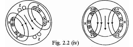
6 Ans.5 The relationship between supply frequency and rotor induced emf frequency can be derived as follows: The frequency of a voltage or current induced due to the relative speed between a vending and a magnetic field is given by the general formula; 120 Where, N = Relative speed between magnetic field and the winding P = Number of poles For a rotor speed N r, the relative speed between the rotating flux and the rotor is Ns-N r. Consequently, the rotor current frequency f is given by; Ans.6 SECTION B Given that, P=4, f=50 Hz, R 2= 0.02Ω, X 2= 0.1Ω, T st= (2/3) T m Now, =, Ω Ω Page 6 of 8
7 Ans.7 The torque produced by three phase induction motor depends upon the following three factors: the magnitude of rotor current, the flux which interact with the rotor of three phase induction motor and is responsible for producing emf in the rotor part of induction motor and the power factor of rotor of the three phase induction motor. Hence Where, T is the torque produced by induction motor, φ is flux responsible of producing induced emf, I 2 is rotor current, cosθ 2 is the power factor of rotor circuit. The flux φ produced by the stator is proportional to stator emf E 1. i.e φ α E1 We know that transformation ratio K is defined as the ratio of secondary voltage (rotor voltage) to that of primary voltage (stator voltage). Hence φ α E2. Now putting the value of flux φ, rotor current I 2, power factor cosθ 2 in the equation of torque we get, If we want to find the maximum value of some quantity then we have to differentiate that quantity with respect to some variable parameter and then put it equal to zero. In this case we have to find the condition for maximum torque so we have to differentiate torque with respect to some variable quantity which is slip, s in this case as all other parameters in the equation of torque remains constant. So, for torque to be maximum, Now differentiate the above equation by using division rule of differentiation. On differentiating and after putting the terms equal to zero we get, Substituting the value of this slip in torque equation, we get the maximum value of torque as, From the above equation it is concluded that, 1. The maximum torque is directly proportional to square of rotor induced emf at the standstill. 2. The maximum torque is inversely proportional to rotor reactance. 3. The maximum torque is independent of rotor resistance. 4. The slip at which maximum torque occur depends upon rotor resistance, R2. So, by varying the rotor resistance, maximum torque can be obtained at any required slip. Page 7 of 8
8 Ans.8 SECTION C. = 87.29%. Ans.9 Given that, R 1 = 0.15Ω, X 1 = 0.44 Ω, R 2 = 0.12 Ω, X 2 = 0.44 Ω, X m = 30 Ω, s= 0.04 As per the given problem statement, R c is neglected Ω The equivalent circuit is shown below cos Page 8 of 8
Lesson 17: Synchronous Machines
 Lesson 17: Synchronous Machines ET 332b Ac Motors, Generators and Power Systems Lesson 17_et332b.pptx 1 Learning Objectives After this presentation you will be able to: Explain how synchronous machines
Introduction to Synchronous. Machines. Kevin Gaughan
 Introduction to Synchronous Machines Kevin Gaughan The Synchronous Machine An AC machine (generator or motor) with a stator winding (usually 3 phase) generating a rotating magnetic field and a rotor carrying
University of Jordan Faculty of Engineering & Technology Electric Power Engineering Department
 University of Jordan Faculty of Engineering & Technology Electric Power Engineering Department EE471: Electrical Machines-II Tutorial # 2: 3-ph Induction Motor/Generator Question #1 A 100 hp, 60-Hz, three-phase
Electric Machines I Three Phase Induction Motor. Dr. Firas Obeidat
 Electric Machines I Three Phase Induction Motor Dr. Firas Obeidat 1 Table of contents 1 General Principles 2 Construction 3 Production of Rotating Field 4 Why Does the Rotor Rotate 5 The Slip and Rotor
INDUCTION MOTOR MODEL AND PARAMETERS
 APPENDIX C INDUCTION MOTOR MODEL AND PARAMETERS C.1 Dynamic Model of the Induction Motor in Stationary Reference Frame A three phase induction machine can be represented by an equivalent two phase machine
Prince Sattam bin Abdulaziz University College of Engineering. Electrical Engineering Department EE 3360 Electrical Machines (II)
") Chapter # 4 Three-Phase Induction Machines 1- Introduction (General Principles) Generally, conversion of electrical power into mechanical power takes place in the rotating part of an electric motor. In
Chapter # 4 Three-Phase Induction Machines 1- Introduction (General Principles) Generally, conversion of electrical power into mechanical power takes place in the rotating part of an electric motor. In
Synchronous Machines
 Synchronous Machines Synchronous generators or alternators are used to convert mechanical power derived from steam, gas, or hydraulic-turbine to ac electric power Synchronous generators are the primary
Chapter 4. Synchronous Generators. Basic Topology
 Basic Topology Chapter 4 ynchronous Generators In stator, a three-phase winding similar to the one described in chapter 4. ince the main voltage is induced in this winding, it is also called armature winding.
EE 742 Chapter 3: Power System in the Steady State. Y. Baghzouz
 EE 742 Chapter 3: Power System in the Steady State Y. Baghzouz Transmission Line Model Distributed Parameter Model: Terminal Voltage/Current Relations: Characteristic impedance: Propagation constant: π
EDEXCEL NATIONALS UNIT 5 - ELECTRICAL AND ELECTRONIC PRINCIPLES. ASSIGNMENT No. 3 - ELECTRO MAGNETIC INDUCTION
 EDEXCEL NATIONALS UNIT 5 - ELECTRICAL AND ELECTRONIC PRINCIPLES ASSIGNMENT No. 3 - ELECTRO MAGNETIC INDUCTION NAME: I agree to the assessment as contained in this assignment. I confirm that the work submitted
3 d Calculate the product of the motor constant and the pole flux KΦ in this operating point. 2 e Calculate the torque.
 Exam Electrical Machines and Drives (ET4117) 11 November 011 from 14.00 to 17.00. This exam consists of 5 problems on 4 pages. Page 5 can be used to answer problem 4 question b. The number before a question
EEE3405 ELECTRICAL ENGINEERING PRINCIPLES 2 - TEST
 ATTEMPT ALL QUESTIONS (EACH QUESTION 20 Marks, FULL MAKS = 60) Given v 1 = 100 sin(100πt+π/6) (i) Find the MS, period and the frequency of v 1 (ii) If v 2 =75sin(100πt-π/10) find V 1, V 2, 2V 1 -V 2 (phasor)
Tutorial Sheet Fig. Q1
 Tutorial Sheet - 04 1. The magnetic circuit shown in Fig. Q1 has dimensions A c = A g = 9 cm 2, g = 0.050 cm, l c = 30 cm, and N = 500 turns. Assume the value of the relative permeability,µ r = 70,000
ROEVER COLLEGE OF ENGINEERING & TECHNOLOGY ELAMBALUR, PERAMBALUR DEPARTMENT OF ELECTRICAL AND ELECTRONICS ENGINEERING ELECTRICAL MACHINES I
 ROEVER COLLEGE OF ENGINEERING & TECHNOLOGY ELAMBALUR, PERAMBALUR-621220 DEPARTMENT OF ELECTRICAL AND ELECTRONICS ENGINEERING ELECTRICAL MACHINES I Unit I Introduction 1. What are the three basic types
Massachusetts Institute of Technology Department of Electrical Engineering and Computer Science Electric Machines
 Massachusetts Institute of Technology Department of Electrical Engineering and Computer Science 6.685 Electric Machines Problem Set 10 Issued November 11, 2013 Due November 20, 2013 Problem 1: Permanent
Electrical Machines and Energy Systems: Operating Principles (Part 2) SYED A Rizvi
 SYED A Rizvi") Electrical Machines and Energy Systems: Operating Principles (Part 2) SYED A Rizvi AC Machines Operating Principles: Synchronous Motor In synchronous motors, the stator of the motor has a rotating magnetic
Electrical Machines and Energy Systems: Operating Principles (Part 2) SYED A Rizvi AC Machines Operating Principles: Synchronous Motor In synchronous motors, the stator of the motor has a rotating magnetic
UNIVERSITY OF SWAZILAND FACULTY OF SCIENCE DEPARTMENT OF ELECTRICAL AND ELECTRONIC ENGINEERING. MAIN EXAMINATION May 2013
 UNIVERSITY OF SWAZILAND FACULTY OF SCIENCE DEPARTMENT OF ELECTRICAL AND ELECTRONIC ENGINEERING MAIN EXAMINATION May 2013 TITLE OF PAPER: Fundamentals of Power Engineering COURSE CODE: EE 351 TIME ALLOWED:
PHASOR DIAGRAM OF TRANSFORMER. Prepared By ELECTRICALBABA.COM
 PHASOR DIAGRAM OF TRANSFORMER Prepared By ELECTRICALBABA.COM IMPORTANT POINTS FOR PHASOR OF TRANSFORMER Transformer when excited at no load, only takes excitation current which leads the working Flux by
Electrical Machines and Energy Systems: Operating Principles (Part 1) SYED A Rizvi
 SYED A Rizvi") Electrical Machines and Energy Systems: Operating Principles (Part 1) SYED A Rizvi AC Machines Operating Principles: Rotating Magnetic Field The key to the functioning of AC machines is the rotating magnetic
Electrical Machines and Energy Systems: Operating Principles (Part 1) SYED A Rizvi AC Machines Operating Principles: Rotating Magnetic Field The key to the functioning of AC machines is the rotating magnetic
Chapter 5 Three phase induction machine (1) Shengnan Li
 Shengnan Li") Chapter 5 Three phase induction machine (1) Shengnan Li Main content Structure of three phase induction motor Operating principle of three phase induction motor Rotating magnetic field Graphical representation
Chapter 5 Three phase induction machine (1) Shengnan Li Main content Structure of three phase induction motor Operating principle of three phase induction motor Rotating magnetic field Graphical representation
Mathematical Model of a Synchronous Machine under Complicated Fault Conditions
 Mathematical Model of a Synchronous Machine under Complicated Fault Conditions Prof. Hani Obeid PhD EE, P.Eng.,SMIEEE, Applied Sciences University, P.O.Box 950674, Amman 11195- Jordan. Abstract This paper
Fachgebiet Leistungselektronik und Elektrische Antriebstechnik. Test Examination: Mechatronics and Electrical Drives
 Prof. Dr. Ing. Joachim Böcker Test Examination: Mechatronics and Electrical Drives 8.1.214 First Name: Student number: Last Name: Course of Study: Exercise: 1 2 3 Total (Points) (2) (2) (2) (6) Duration:
Ph.D. Qualifying Exam. Electrical Engineering Part I
 Ph.D. Qualifying Exam February 5th, 2015 1:00-5:00pm Electrical Engineering Part I Instructions: This is a closed-book/closed-notes exam module, four hours in duration. There are ten (10) problems in this
د شوقي حامد عرفه ابراهيم
 2015 /1/19 اإلجابة النموذجية لمادة نظم التشغيل الكهربية ك 563 د شوقي حامد عرفه ابراهيم يوم االثنين الموافق Benha University Benha Faculty of Engineering Subject: Electrical drives (E563) Time: 3hours Fifth
Induction Motors. The single-phase induction motor is the most frequently used motor in the world
 Induction Motor The single-phase induction motor is the most frequently used motor in the world Most appliances, such as washing machines and refrigerators, use a single-phase induction machine Highly
R13 SET Derive the expression for the maximum bending stress developed in the leaf spring and also the central deflection of a leaf spring.
 Code No: RT22013 R13 SET - 41 STRENGTH OF MATERIALS - II (Civil Engineering) Time: 3 hours Max. Marks: 70 Note: 1. Question Paper consists of two parts (Part-A and Part-B) 2. Answer ALL the question in
LAB REPORT: THREE-PHASE INDUCTION MACHINE
 LAB REPORT: THREE-PHASE INDUCTION MACHINE ANDY BENNETT 1. Summary This report details the operation, modelling and characteristics of a three-phase induction machine. It attempts to provide a concise overview
Electromagnetic Energy Conversion Exam 98-Elec-A6 Spring 2002
 Front Page Electromagnetic Energy Conversion Exam 98-Elec-A6 Spring 2002 Notes: Attempt question 1 and FOUR (4) other questions (FVE (5) questions in all). Unless you indicate otherwise, the first five
ELECTRICALMACHINES-I QUESTUION BANK
 ELECTRICALMACHINES-I QUESTUION BANK UNIT-I INTRODUCTION OF MAGNETIC MATERIAL PART A 1. What are the three basic rotating Electric machines? 2. Name the three materials used in machine manufacture. 3. What
Revision Guide for Chapter 15
 Revision Guide for Chapter 15 Contents tudent s Checklist Revision otes Transformer... 4 Electromagnetic induction... 4 Generator... 5 Electric motor... 6 Magnetic field... 8 Magnetic flux... 9 Force on
ECE 325 Electric Energy System Components 7- Synchronous Machines. Instructor: Kai Sun Fall 2015
 ECE 325 Electric Energy System Components 7- Synchronous Machines Instructor: Kai Sun Fall 2015 1 Content (Materials are from Chapters 16-17) Synchronous Generators Synchronous Motors 2 Synchronous Generators
Definition Application of electrical machines Electromagnetism: review Analogies between electric and magnetic circuits Faraday s Law Electromagnetic
 Definition Application of electrical machines Electromagnetism: review Analogies between electric and magnetic circuits Faraday s Law Electromagnetic Force Motor action Generator action Types and parts
Generators. What its all about
 Generators What its all about How do we make a generator? Synchronous Operation Rotor Magnetic Field Stator Magnetic Field Forces and Magnetic Fields Force Between Fields Motoring Generators & motors are
Dynamics of the synchronous machine
 ELEC0047 - Power system dynamics, control and stability Dynamics of the synchronous machine Thierry Van Cutsem t.vancutsem@ulg.ac.be www.montefiore.ulg.ac.be/~vct October 2018 1 / 38 Time constants and
Tutorial 1 (EMD) Rotary field winding
 Rotary field winding") Tutorial 1 (EMD) Rotary field winding The unchorded two-layer three-phase winding of a small synchronous fan drive for a computer has the following parameters: number of slots per pole and phase q = 1,
Tutorial 1 (EMD) Rotary field winding The unchorded two-layer three-phase winding of a small synchronous fan drive for a computer has the following parameters: number of slots per pole and phase q = 1,
Motor Info on the WWW Motorola Motors DC motor» /MOTORDCTUT.
 Motor Info on the WWW Motorola Motors DC motor» http://www.freescale.com/files/microcontrollers/doc/train_ref_material /MOTORDCTUT.html Brushless DC motor» http://www.freescale.com/files/microcontrollers/doc/train_ref_material
Model of a DC Generator Driving a DC Motor (which propels a car)
") Model of a DC Generator Driving a DC Motor (which propels a car) John Hung 5 July 2011 The dc is connected to the dc as illustrated in Fig. 1. Both machines are of permanent magnet type, so their respective
Model of a DC Generator Driving a DC Motor (which propels a car) John Hung 5 July 2011 The dc is connected to the dc as illustrated in Fig. 1. Both machines are of permanent magnet type, so their respective
ENGG4420 LECTURE 7. CHAPTER 1 BY RADU MURESAN Page 1. September :29 PM
 CHAPTER 1 BY RADU MURESAN Page 1 ENGG4420 LECTURE 7 September 21 10 2:29 PM MODELS OF ELECTRIC CIRCUITS Electric circuits contain sources of electric voltage and current and other electronic elements such
Step Motor Modeling. Step Motor Modeling K. Craig 1
 Step Motor Modeling Step Motor Modeling K. Craig 1 Stepper Motor Models Under steady operation at low speeds, we usually do not need to differentiate between VR motors and PM motors (a hybrid motor is
Chapter 6. Induction Motors. Copyright The McGraw-Hill Companies, Inc. Permission required for reproduction or display.
 Chapter 6 Induction Motors 1 The Development of Induced Torque in an Induction Motor Figure 6-6 The development of induced torque in an induction motor. (a) The rotating stator field B S induces a voltage
Synchronous Machines
 Synchronous Machines Synchronous Machines n 1 Φ f n 1 Φ f I f I f I f damper (run-up) winding Stator: similar to induction (asynchronous) machine ( 3 phase windings that forms a rotational circular magnetic
Mechatronics Engineering. Li Wen
 Mechatronics Engineering Li Wen Bio-inspired robot-dc motor drive Unstable system Mirko Kovac,EPFL Modeling and simulation of the control system Problems 1. Why we establish mathematical model of the control
UNIT I INTRODUCTION Part A- Two marks questions
 ROEVER COLLEGE OF ENGINEERING & TECHNOLOGY ELAMBALUR, PERAMBALUR-621220 DEPARTMENT OF ELECTRICAL AND ELECTRONICS ENGINEERING DESIGN OF ELECTRICAL MACHINES UNIT I INTRODUCTION 1. Define specific magnetic
Dynamic Modeling of Surface Mounted Permanent Synchronous Motor for Servo motor application
 797 Dynamic Modeling of Surface Mounted Permanent Synchronous Motor for Servo motor application Ritu Tak 1, Sudhir Y Kumar 2, B.S.Rajpurohit 3 1,2 Electrical Engineering, Mody University of Science & Technology,
AC Circuits Homework Set
 Problem 1. In an oscillating LC circuit in which C=4.0 μf, the maximum potential difference across the capacitor during the oscillations is 1.50 V and the maximum current through the inductor is 50.0 ma.
CHAPTER 5 SIMULATION AND TEST SETUP FOR FAULT ANALYSIS
 47 CHAPTER 5 SIMULATION AND TEST SETUP FOR FAULT ANALYSIS 5.1 INTRODUCTION This chapter describes the simulation model and experimental set up used for the fault analysis. For the simulation set up, the
Analytical and numerical computation of the no-load magnetic field in induction motors
 Analytical and numerical computation of the no-load induction motors Dan M. Ionel University of Glasgow, Glasgow, Scotland, UK and Mihai V. Cistelecan Research Institute for Electrical Machines, Bucharest
ELECTROMAGNETIC OSCILLATIONS AND ALTERNATING CURRENT
 Chapter 31: ELECTROMAGNETIC OSCILLATIONS AND ALTERNATING CURRENT 1 A charged capacitor and an inductor are connected in series At time t = 0 the current is zero, but the capacitor is charged If T is the
SHORT QUESTIONS AND ANSWERS. Year/ Semester/ Class : III/ V/ EEE Academic Year: Subject Code/ Name: EE6501/ Power System Analysis
 Srividya colllege of Engg & Tech,Virudhunagar Sri Vidya College of Engineering And Technology Virudhunagar 626 005 Department of Electrical and Electronics Engineering QUESTION BANK SHORT QUESTIONS AND
Keywords: Electric Machines, Rotating Machinery, Stator faults, Fault tolerant control, Field Weakening, Anisotropy, Dual rotor, 3D modeling
 Analysis of Electromagnetic Behavior of Permanent Magnetized Electrical Machines in Fault Modes M. U. Hassan 1, R. Nilssen 1, A. Røkke 2 1. Department of Electrical Power Engineering, Norwegian University
Chapter 3 AUTOMATIC VOLTAGE CONTROL
 Chapter 3 AUTOMATIC VOLTAGE CONTROL . INTRODUCTION TO EXCITATION SYSTEM The basic function of an excitation system is to provide direct current to the field winding of the synchronous generator. The excitation
Mathematical MATLAB Model and Performance Analysis of Asynchronous Machine
 Mathematical MATLAB Model and Performance Analysis of Asynchronous Machine Bikram Dutta 1, Suman Ghosh 2 Assistant Professor, Dept. of EE, Guru Nanak Institute of Technology, Kolkata, West Bengal, India
Lecture 9: Space-Vector Models
 1 / 30 Lecture 9: Space-Vector Models ELEC-E8405 Electric Drives (5 ECTS) Marko Hinkkanen Autumn 2017 2 / 30 Learning Outcomes After this lecture and exercises you will be able to: Include the number of
International Journal of Advance Engineering and Research Development SIMULATION OF FIELD ORIENTED CONTROL OF PERMANENT MAGNET SYNCHRONOUS MOTOR
 Scientific Journal of Impact Factor(SJIF): 3.134 e-issn(o): 2348-4470 p-issn(p): 2348-6406 International Journal of Advance Engineering and Research Development Volume 2,Issue 4, April -2015 SIMULATION
Behaviour of synchronous machine during a short-circuit (a simple example of electromagnetic transients)
") ELEC0047 - Power system dynamics, control and stability (a simple example of electromagnetic transients) Thierry Van Cutsem t.vancutsem@ulg.ac.be www.montefiore.ulg.ac.be/~vct October 2018 1 / 25 Objectives
ELEC0047 - Power system dynamics, control and stability (a simple example of electromagnetic transients) Thierry Van Cutsem t.vancutsem@ulg.ac.be www.montefiore.ulg.ac.be/~vct October 2018 1 / 25 Objectives
Transformer Fundamentals
 Transformer Fundamentals 1 Introduction The physical basis of the transformer is mutual induction between two circuits linked by a common magnetic field. Transformer is required to pass electrical energy
The synchronous machine (detailed model)
") ELEC0029 - Electric Power System Analysis The synchronous machine (detailed model) Thierry Van Cutsem t.vancutsem@ulg.ac.be www.montefiore.ulg.ac.be/~vct February 2018 1 / 6 Objectives The synchronous
ELEC0029 - Electric Power System Analysis The synchronous machine (detailed model) Thierry Van Cutsem t.vancutsem@ulg.ac.be www.montefiore.ulg.ac.be/~vct February 2018 1 / 6 Objectives The synchronous
Revision Guide for Chapter 15
 Revision Guide for Chapter 15 Contents Revision Checklist Revision otes Transformer...4 Electromagnetic induction...4 Lenz's law...5 Generator...6 Electric motor...7 Magnetic field...9 Magnetic flux...
DESIGN OF ELECTRICAL APPARATUS SOLVED PROBLEMS
 DESIGN OF ELECTRICAL APPARATUS SOLVED PROBLEMS 1. A 350 KW, 500V, 450rpm, 6-pole, dc generator is built with an armature diameter of 0.87m and core length of 0.32m. The lap wound armature has 660 conductors.
How an Induction Motor Works by Equations (and Physics)
") How an Induction Motor Works by Equations (and Physics) The magnetic field in the air gap from the voltage applied to the stator: The stator has three sets of windings that are aligned at 10 degrees to
How an Induction Motor Works by Equations (and Physics) The magnetic field in the air gap from the voltage applied to the stator: The stator has three sets of windings that are aligned at 10 degrees to
Texas A & M University Department of Mechanical Engineering MEEN 364 Dynamic Systems and Controls Dr. Alexander G. Parlos
 Texas A & M University Department of Mechanical Engineering MEEN 364 Dynamic Systems and Controls Dr. Alexander G. Parlos Lecture 6: Modeling of Electromechanical Systems Principles of Motor Operation
(a) Torsional spring-mass system. (b) Spring element.
 Torsional spring-mass system. (b) Spring element.") m v s T s v a (a) T a (b) T a FIGURE 2.1 (a) Torsional spring-mass system. (b) Spring element. by ky Wall friction, b Mass M k y M y r(t) Force r(t) (a) (b) FIGURE 2.2 (a) Spring-mass-damper system. (b)
m v s T s v a (a) T a (b) T a FIGURE 2.1 (a) Torsional spring-mass system. (b) Spring element. by ky Wall friction, b Mass M k y M y r(t) Force r(t) (a) (b) FIGURE 2.2 (a) Spring-mass-damper system. (b)
Motor-CAD combined electromagnetic and thermal model (January 2015)
") Motor-CAD combined electromagnetic and thermal model (January 2015) Description The Motor-CAD allows the machine performance, losses and temperatures to be calculated for a BPM machine. In this tutorial
Motor-CAD combined electromagnetic and thermal model (January 2015) Description The Motor-CAD allows the machine performance, losses and temperatures to be calculated for a BPM machine. In this tutorial
An Introduction to Electrical Machines. P. Di Barba, University of Pavia, Italy
 An Introduction to Electrical Machines P. Di Barba, University of Pavia, Italy Academic year 0-0 Contents Transformer. An overview of the device. Principle of operation of a single-phase transformer 3.
Mutual Inductance. The field lines flow from a + charge to a - change
 Capacitors Mutual Inductance Since electrical charges do exist, electric field lines have a starting point and an ending point. For example, if you have a + and a - change, the field lines would look something
SCHOOL OF ELECTRICAL, MECHANICAL AND MECHATRONIC SYSTEMS. Transient Stability LECTURE NOTES SPRING SEMESTER, 2008
 SCHOOL OF ELECTRICAL, MECHANICAL AND MECHATRONIC SYSTEMS LECTURE NOTES Transient Stability SPRING SEMESTER, 008 October 7, 008 Transient Stability Transient stability refers to the ability of a synchronous
Generators for wind power conversion
 Generators for wind power conversion B. G. Fernandes Department of Electrical Engineering Indian Institute of Technology, Bombay Email : bgf@ee.iitb.ac.in Outline of The Talk Introduction Constant speed
The synchronous machine (SM) in the power system (2) (Where does the electricity come from)?
 in the power system (2) (Where does the electricity come from)?") 1 The synchronous machine (SM) in the power system (2) (Where does the electricity come from)? 2 Lecture overview Synchronous machines with more than 2 magnetic poles The relation between the number of
1 The synchronous machine (SM) in the power system (2) (Where does the electricity come from)? 2 Lecture overview Synchronous machines with more than 2 magnetic poles The relation between the number of
Measurements of a 37 kw induction motor. Rated values Voltage 400 V Current 72 A Frequency 50 Hz Power 37 kw Connection Star
 Measurements of a 37 kw induction motor Rated values Voltage 4 V Current 72 A Frequency 5 Hz Power 37 kw Connection Star Losses of a loaded machine Voltage, current and power P = P -w T loss in Torque
THREE PHASE SYSTEMS Part 1
 ERT105: ELECTRCAL TECHNOLOGY CHAPTER 3 THREE PHASE SYSTEMS Part 1 1 Objectives Become familiar with the operation of a three phase generator and the magnitude and phase relationship. Be able to calculate
Time-Harmonic Modeling of Squirrel-Cage Induction Motors: A Circuit-Field Coupled Approach
 Time-Harmonic Modeling of Squirrel-Cage Induction Motors: A Circuit-Field Coupled Approach R. Escarela-Perez 1,3 E. Melgoza 2 E. Campero-Littlewood 1 1 División de Ciencias Básicas e Ingeniería, Universidad
EC T32 - ELECTRICAL ENGINEERING
 EC T32 - ELECTRICAL ENGINEERING UNIT-I - TRANSFORMER 1. What is a transformer? 2. Briefly explain the principle of operation of transformers. 3. What are the parts of a transformer? 4. What are the types
Parameter Estimation of Three Phase Squirrel Cage Induction Motor
 International Conference On Emerging Trends in Mechanical and Electrical Engineering RESEARCH ARTICLE OPEN ACCESS Parameter Estimation of Three Phase Squirrel Cage Induction Motor Sonakshi Gupta Department
LESSON 20 ALTERNATOR OPERATION OF SYNCHRONOUS MACHINES
 ET 332b Ac Motors, Generators and Power Systems LESSON 20 ALTERNATOR OPERATION OF SYNCHRONOUS MACHINES 1 LEARNING OBJECTIVES After this presentation you will be able to: Interpret alternator phasor diagrams
1 Fig. 3.1 shows the variation of the magnetic flux linkage with time t for a small generator. magnetic. flux linkage / Wb-turns 1.
 1 Fig. 3.1 shows the variation of the magnetic flux linkage with time t for a small generator. 2 magnetic 1 flux linkage / 0 10 2 Wb-turns 1 2 5 10 15 t / 10 3 s Fig. 3.1 The generator has a flat coil
Time: 2 hours. On the answer-booklet write your Registration Number, Test Code, Number of this Booklet, etc. in the appropriate places.
 BOOKLET No. 2016 Time: 2 hours TEST CODE: PQB Afternoon Group Total Part I (for Statistics/Mathematics Stream) S1 (Statistics) 5 S2 (Probability) 5 Part II (for Engineering Stream) E1 (Mathematics) 4 E2
Analytical Model for Sizing the Magnets of Permanent Magnet Synchronous Machines
 Journal of Electrical Engineering 3 (2015) 134-141 doi: 10.17265/2328-2223/2015.03.004 D DAVID PUBLISHING Analytical Model for Sizing Magnets of Permanent Magnet Synchronous Machines George Todorov and
Synchronous Machines
 Synchronous machine 1. Construction Generator Exciter View of a twopole round rotor generator and exciter. A Stator with laminated iron core C Slots with phase winding B A B Rotor with dc winding B N S
mywbut.com Lesson 16 Solution of Current in AC Parallel and Seriesparallel
 esson 6 Solution of urrent in Parallel and Seriesparallel ircuits n the last lesson, the following points were described:. How to compute the total impedance/admittance in series/parallel circuits?. How
MODELING AND HIGH-PERFORMANCE CONTROL OF ELECTRIC MACHINES
 MODELING AND HIGH-PERFORMANCE CONTROL OF ELECTRIC MACHINES JOHN CHIASSON IEEE PRESS ü t SERIES ON POWER ENGINEERING IEEE Press Series on Power Engineering Mohamed E. El-Hawary, Series Editor The Institute
Doubly salient reluctance machine or, as it is also called, switched reluctance machine. [Pyrhönen et al 2008]
![Doubly salient reluctance machine or, as it is also called, switched reluctance machine. [Pyrhönen et al 2008]](/thumbs/86/93665357.jpg "Doubly salient reluctance machine or, as it is also called, switched reluctance machine. [Pyrhönen et al 2008]") Doubly salient reluctance machine or, as it is also called, switched reluctance machine [Pyrhönen et al 2008] Pros and contras of a switched reluctance machine Advantages Simple robust rotor with a small
Doubly salient reluctance machine or, as it is also called, switched reluctance machine [Pyrhönen et al 2008] Pros and contras of a switched reluctance machine Advantages Simple robust rotor with a small
Overview: Induction Motors. Review Questions. Why the Rotor Moves: Motor Speed
 Overview: nduction Motor Motor operation & Slip Speed-torque relationhip Equivalent circuit model Tranformer Motor efficiency Starting induction motor Smith College, EGR 35 ovember 5, 04 Review Quetion
CHAPTER 22 ELECTROMAGNETIC INDUCTION
 CHAPTER 22 ELECTROMAGNETIC INDUCTION PROBLEMS 47. REASONING AND Using Equation 22.7, we find emf 2 M I or M ( emf 2 ) t ( 0.2 V) ( 0.4 s) t I (.6 A) ( 3.4 A) 9.3 0 3 H 49. SSM REASONING AND From the results
Equivalent Circuits with Multiple Damper Windings (e.g. Round rotor Machines)
") Equivalent Circuits with Multiple Damper Windings (e.g. Round rotor Machines) d axis: L fd L F - M R fd F L 1d L D - M R 1d D R fd R F e fd e F R 1d R D Subscript Notations: ( ) fd ~ field winding quantities
Equivalent Circuits with Multiple Damper Windings (e.g. Round rotor Machines) d axis: L fd L F - M R fd F L 1d L D - M R 1d D R fd R F e fd e F R 1d R D Subscript Notations: ( ) fd ~ field winding quantities
Module 4. Single-phase AC circuits. Version 2 EE IIT, Kharagpur
 Module 4 Single-phase circuits ersion EE T, Kharagpur esson 6 Solution of urrent in Parallel and Seriesparallel ircuits ersion EE T, Kharagpur n the last lesson, the following points were described:. How
Post-Test. For more information, please contact the MCU Training Team.
 Answer the following application questions based on this diagram. Multiple Choice 1. What type of application curve must be used inside a VFD to operate this carpet roll correctly? A) Constant Torque B)
ECE 585 Power System Stability
 Homework 1, Due on January 29 ECE 585 Power System Stability Consider the power system below. The network frequency is 60 Hz. At the pre-fault steady state (a) the power generated by the machine is 400
Tutorial 1 - Drive fundamentals and DC motor characteristics
 University of New South Wales School of Electrical Engineering & elecommunications ELEC4613 ELECRIC DRIVE SYSEMS utorial 1 - Drive fundamentals and DC motor characteristics 1. In the hoist drive system
EE 6501 POWER SYSTEMS UNIT I INTRODUCTION
 EE 6501 POWER SYSTEMS UNIT I INTRODUCTION PART A (2 MARKS) 1. What is single line diagram? A Single line diagram is diagrammatic representation of power system in which the components are represented by
Control of Wind Turbine Generators. James Cale Guest Lecturer EE 566, Fall Semester 2014 Colorado State University
 Control of Wind Turbine Generators James Cale Guest Lecturer EE 566, Fall Semester 2014 Colorado State University Review from Day 1 Review Last time, we started with basic concepts from physics such as
From now, we ignore the superbar - with variables in per unit. ψ ψ. l ad ad ad ψ. ψ ψ ψ
 From now, we ignore the superbar - with variables in per unit. ψ 0 L0 i0 ψ L + L L L i d l ad ad ad d ψ F Lad LF MR if = ψ D Lad MR LD id ψ q Ll + Laq L aq i q ψ Q Laq LQ iq 41 Equivalent Circuits for
The initial magnetization curve shows the magnetic flux density that would result when an increasing magnetic field is applied to an initially
 MAGNETIC CIRCUITS The study of magnetic circuits is important in the study of energy systems since the operation of key components such as transformers and rotating machines (DC machines, induction machines,
MAHARASHTRA STATE BOARD OF TECHNICAL EDUCATION
 Important Instructions to examiners: 1) The answers should be examined by key words and not as word-to-word as given in the model answer scheme. 2) The model answer and the answer written by candidate
CHAPTER 2 DYNAMIC STABILITY MODEL OF THE POWER SYSTEM
 20 CHAPTER 2 DYNAMIC STABILITY MODEL OF THE POWER SYSTEM 2. GENERAL Dynamic stability of a power system is concerned with the dynamic behavior of the system under small perturbations around an operating
SECTION - I. PULL-IN-OPERATION Op SYNCHRONOUS MOTORS
 SECTION - I PULL-IN-OPERATION Op SYNCHRONOUS MOTORS 14 S 1.1 INTRODUCTION The starting of synchronous, reluctance and permanent magnet synchronous motors is normally carried out by damper winding. The
INSTITUTE OF AERONAUTICAL ENGINEERING (Autonomous)
") INSTITUTE OF AERONAUTICAL ENGINEERING (Autonomous) Dundigal, Hyderabad - 500 043 ELECTRICAL AND ELECTRONICS ENGINEERING QUESTION BANK Course Name : Computer Methods in Power Systems Course Code : A60222
INSTITUTE OF AERONAUTICAL ENGINEERING (Autonomous) Dundigal, Hyderabad - 500 043 ELECTRICAL AND ELECTRONICS ENGINEERING QUESTION BANK Course Name : Computer Methods in Power Systems Course Code : A60222
ADMISSION TEST INDUSTRIAL AUTOMATION ENGINEERING
 UNIVERSITÀ DEGLI STUDI DI PAVIA ADMISSION TEST INDUSTRIAL AUTOMATION ENGINEERING September 26, 2016 The candidates are required to answer the following multiple choice test which includes 30 questions;
1439. Numerical simulation of the magnetic field and electromagnetic vibration analysis of the AC permanent-magnet synchronous motor
 1439. Numerical simulation of the magnetic field and electromagnetic vibration analysis of the AC permanent-magnet synchronous motor Bai-zhou Li 1, Yu Wang 2, Qi-chang Zhang 3 1, 2, 3 School of Mechanical
Mathematical Modeling and Dynamic Simulation of a Class of Drive Systems with Permanent Magnet Synchronous Motors
 Applied and Computational Mechanics 3 (2009) 331 338 Mathematical Modeling and Dynamic Simulation of a Class of Drive Systems with Permanent Magnet Synchronous Motors M. Mikhov a, a Faculty of Automatics,
PARAMETER SENSITIVITY ANALYSIS OF AN INDUCTION MOTOR
 HUNGARIAN JOURNAL OF INDUSTRIAL CHEMISTRY VESZPRÉM Vol. 39(1) pp. 157-161 (2011) PARAMETER SENSITIVITY ANALYSIS OF AN INDUCTION MOTOR P. HATOS, A. FODOR, A. MAGYAR University of Pannonia, Department of