Synchronous Machines
|
|
|
- Lindsey Peters
- 6 years ago
- Views:
Transcription
1 Synchronous Machines
2 Synchronous Machines n 1 Φ f n 1 Φ f I f I f I f damper (run-up) winding Stator: similar to induction (asynchronous) machine ( 3 phase windings that forms a rotational circular magnetic field ) n 1 = 60.f 1 / p Rotor: I f DC. + slip rings circular field Φ f ~ I f Rotor design: a) salient pole b) cylindrical (round / non salient pole) rotor (turbo)

3 ČKD kw, 10 kv, 2p= to 3900 min -1

4 Rotor of a Turbomotor
5 Rotor of a Salient Pole Machine Run-up squirrel cage (damper winding)

6 ČKD kw, 6 kv, 2p=4 Synchronous Motor

7 ČKD kw, 6 kv, 2p=4

8 ČKD kva, 11 kv, 2p=8 Synchronous Generator

9 ČKD 2500 kw 10 kv, 2p=40 synchr.
10 Rotor of a Turbomachine Cross Section
11 Detail of a Nonmagnetic Armature of a Turbomachine
12 Rotor of a Slow Speed Machine Magnet wheel Hub Shaft
13 Magnetic Flux within a Salient Pole Machine
 voltage - Voltage induced by excitation current I f U ˆ ˆ creates current Î, that flows through")
14 Fluxes and Reactances Resulting field is excited by the electromotive force produced by currents in three phase windings of the stator and DC current in excitation (field) winding in the rotor. Resulting fictional magnetizing current: In stator: Uˆ Uˆif I ˆ = Iˆ + µ - Supply (power grid) voltage - Voltage induced by excitation current I f U ˆ ˆ creates current Î, that flows through resistance U if and longitudinal synchronous reactance X d. X d = X ad + Φ ad main flux, Iˆ f X 1σ (interacts with rotor winding) Φ 1σ leakage (stray) flux X ad - longitudinal reactance of backelectromotive force of the rotor Similarly, the lateral synchronous reactance X q can be derived.
15 Synchronous Alternator with a Cylindrical Rotor Assumptions: a) Air gap is constant along the whole circumference δ = konst. R = m δ konst. b) Stator and rotor electromotive forces are sinusoidal distributed in space F m = F max π sin α τ p c) Angular velocity of rotor rotation is equal to d) Permeability ω = 2πf = konst. µ = konst. Φ ~ F m
16 Voltage Equations Uˆ = RIˆ + jx Iˆ σ + U = R I f f f ˆ U i If equation U i =4,44 f 1 Φ µ N 1 k v1 ~ Φ µ ~ F µ is valid, then also equations Fˆ = Fˆ f + Fˆ µ a are valid. Φ ˆ =Φ ˆ + Φˆ µ Uˆ = Uˆ + Uˆ i f f a a
17 For cylindrical rotor: X d = X q = X s = X ad + X 1σ Voltage equation has following form: or U ˆ = RIˆ + jx Iˆ + ˆ d U if U ˆ RIˆ + jx Iˆ + jx Iˆ + Uˆ = σ ad if
18 Phasor Diagram of a Turboalternator
19 Asynchronous Run-up of a Synchronous Motor n n 1 A A n n' < n 1 Synchronization: S of rotor tightens to J of stator Permanent coupling betweenφ f a Φ a : n = n 1 = konst = f (f ) M
20 Asynchronous run-up of synchronous motor n' n'' n n 1 A A' A'' n'' < < n 1 No synchronization M
21 Loading of a Synchronous Motor Increase of load torque M p S J n 1 Φ a n S Φ f J n = n 1
22 Loading of a Synchronous Motor Increase of load torque M p S n 1 Φ a J δ n = n 1 Rotor field is delayed behind the stator field of torque angle δ.
23 Loading of a Synchronous Motor Increase of load torque M p S n 1 Φ a J n = n 1
24 Loading of a Synchronous Motor Increase of load torque M p S n 1 Φ a J S n Φ f J n = n 1
25 Loading of a Synchronous Generator - Alternator Increase of driving torque M p S J n 1 Φ a n S Φ f J n = n 1
26 Loading of a Synchronous Generator - Alternator Increase of driving torque M p S n 1 Φ a J n = n 1
27 Loading of a Synchronous Generator - Alternator Increase of driving torque M p S n 1 Φ a J n = n 1
28 Loading of a Synchronous Generator - Alternator Increase of driving torque M p S n 1 Φ a J S Φf n J n = n 1
29 Basic Equivalent Circuit of a Turbomachine ~ U if X d I U X d - synchronous reactance (respests existence of stray flux and flux generated by current I ) R 1 = 0 - negligible compared to X d Uˆ = Uˆ + if jx d Iˆ
30 Loading at a Constant Power while Connected to a Strong Grid X d I jx d I w ~ U if U jx d.i q U I w φ I U if Important: I w = I cosφ ~ M X d I w = U if sinδ δ p I I q p U
31 Loading at a Constant Power while Connected to a Strong Grid X d I jx d I w ~ U if U U U if I=I w δ
32 Loading at a Constant Power while Connected to a Strong Grid X d I jx d I w jx d.i q ~ U if U U U if φ I I w δ I q Advantages of a synchronous motor: n = n 1 = konst. Change of cos φ
33 Phasor Diagram of an Overexcited Turbomachine X d I motor ~ U if U generator φ U jx d.i w U if jx d.i q jx d.i q U if jx d I w U I I w δ δ I q I q I I w
34 Regulation of Real and Reactive Power
35 Loading at a Constant Power while Connected to a Strong Grid All currents are recalculated to stator
36 Loading at a Constant Power while Connected to a Strong Grid V-curve of a synchronous machine
37 Loading at a Constant Excitation while Connected to a Strong Grid I μ is a magnetizing current in stator needed for excitation of a nominal voltage in idle run. It is constant if connected to a strong grid.
38 Torque of a Turbomachine P m = m U I cosφ = M ω 1m X d I w = U if sinδ M = m ω UU X 1m d if sinδ
39 Loading at a Constant Excitation while Connected to a Strong Grid Static stability a overload capacity Stable run: dp > 0 dδ Synchronizing factor: dp = m dδ 1 U U 1 X d if cosδ Determines ability of the machine to stay in synchronism. Maximum at δ = 0.
40 Loading at a Constant Excitation while Connected to a Strong Grid Static stability and overload capacity dp Synchronizing factor: Stable run: > 0 dδ dp U1U if = m1 cosδ δ d X Synchronizing power: dp dδ δ Indicates size of static stability of an alternator in a given working point in torque angle if the machine is able to get stable in a new point of a power characteristics after change of power without change of excitation d
41 Loading at a Constant Excitation while Connected to a Strong Grid Static stability and overload capacity Stable run: dp > 0 dδ Synchronizing factor: dp U1U if = m1 cosδ dδ X Synchronizing power: Power overload capacity: p M = P P max = N d dp dδ δ M M max N Motor p M 1,5 Alternator p M 1,25
42 Power (Torque) Overload Capacity p p M M P P N M M max max = = Motor p M 1,5 Alternator p M 1,25 = N muu ω X mui ω 1 m d d = = N cosϕn I N cosϕn 1m if U X if I N I kn cosϕ N I kn is steady short-circuit current that corresponds to an excitation current I fn p M = I fkn I fn I fn = ik cosϕ I 0 cosϕ N f N N Overload capacity is bigger when short-circuit ratio i k is higher and cosφ N is lower 1 ik bigger air gap higher excitation power larger dimensions X d
43 Power (Torque) Overload Capacity Conclusions: Short-circuit ratio is smaller when electrical and magnetic utilization of the machine is higher. Stability is provided by fast voltage regulators. Nominal power factor depends on design of excitation winding. Synchronous generators normally have cosφ N = 0,8 big ones up to 0,85 0,9.
44 Torque of a Salient Pole Synchronous Machine
45 Stand-alone Alternator No-load characteristics U 0 I = 0, n = konst. I f
46 Stand-alone Alternator External characteristics I f = const. cos φ = const. n = const.
47 Synchronization of Generator (Connecting to the Grid) Same phase sequences of generator and grid Same frequency Same voltages Same phase in the instant of connection U 0 f = p. n 1 60 I f
48 Dimensions of Turbomachines Power Bearing span Rotor diameter (MW) (mm) (mm)
49 Excitation Systems of Synchronous Machines Excitation from rotary converters 1 synchronous machine 2 dynamo 3 auxiliary driver
50 Excitation Systems of Synchronous Machines Excitation from alternate driver 4 system for excitation current control
51 Excitation Systems of Synchronous Machines Excitation with carried rectifier (brushless excitation system)
52 Excitation Systems of Synchronous Machines Excitation from a system with a rotary transformer 4 AC voltage controller
53 Excitation Systems of Synchronous Machines Excitation from a static converter

54 Excitation Systems of Synchronous Machines Excitation with permanent magnets
 Permanent magnet J S Pole")
55 Small synchronous machines Reluctance motor (without excitation winding) Clutches generator (Klauenpol maschine, drápkový generátor) Permanent magnet J S Pole extenders
56 Brushless DC Motor Commonly called: EC motor, BLDC motor - Properties similar to DC motor - Construction similar to a synchronous machine (3-phase stator winding, rotating manets) - Feeding according to rotor position Sources from company UZIMEX, that supplies motors of the company MAXON.

57 Components of a BLDC drive Power supply Mechanical part Load Electrical part Commutation and control Hall probes encoder commands Electronic part
58 Course of commutation
59 Course of commutation Coil 15 Coil Coil
60
61
62
63

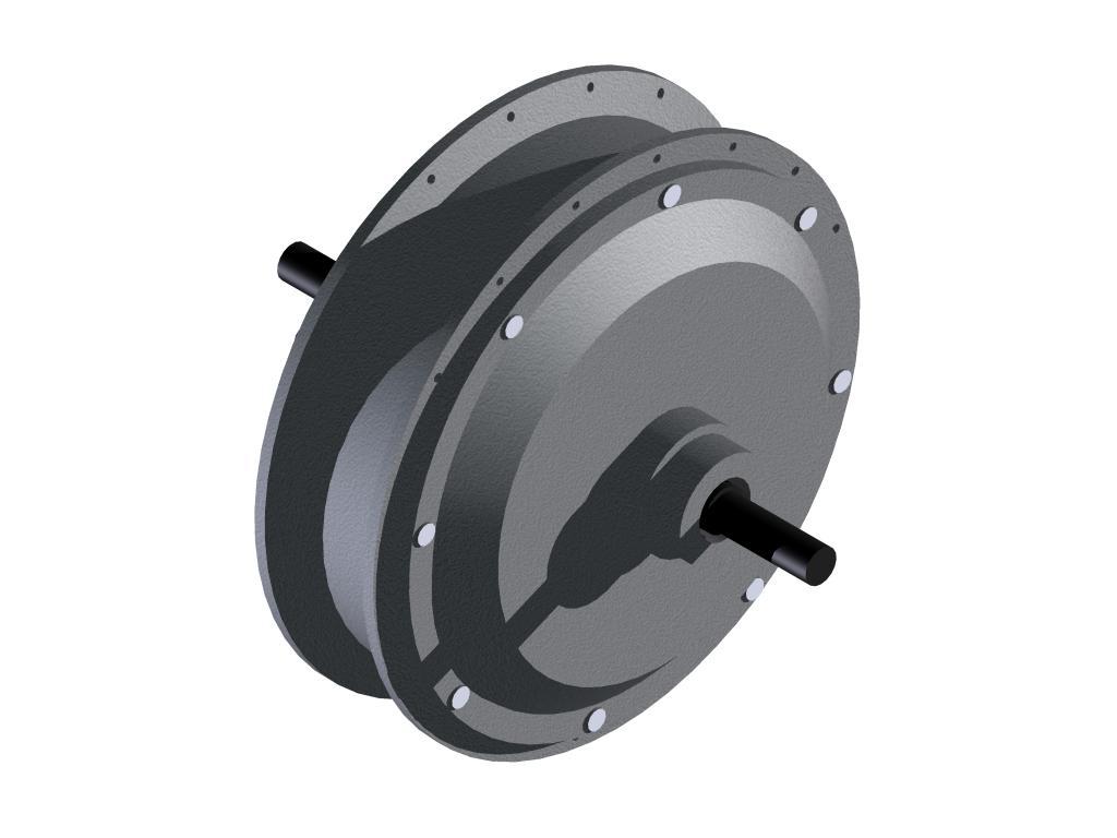
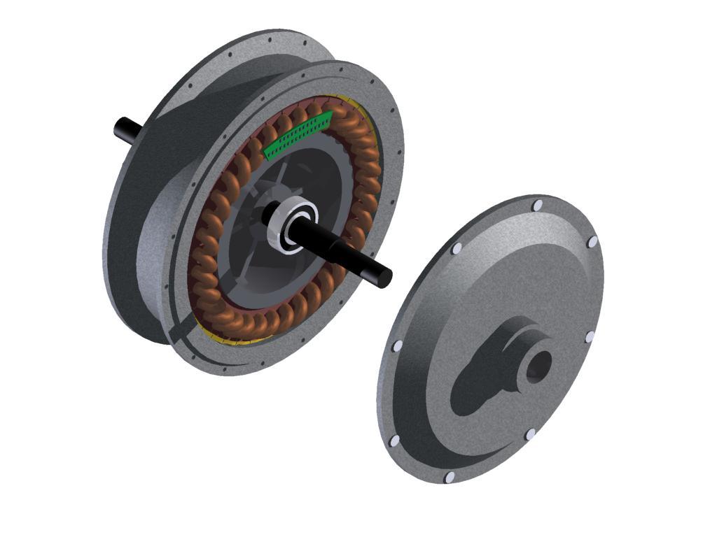
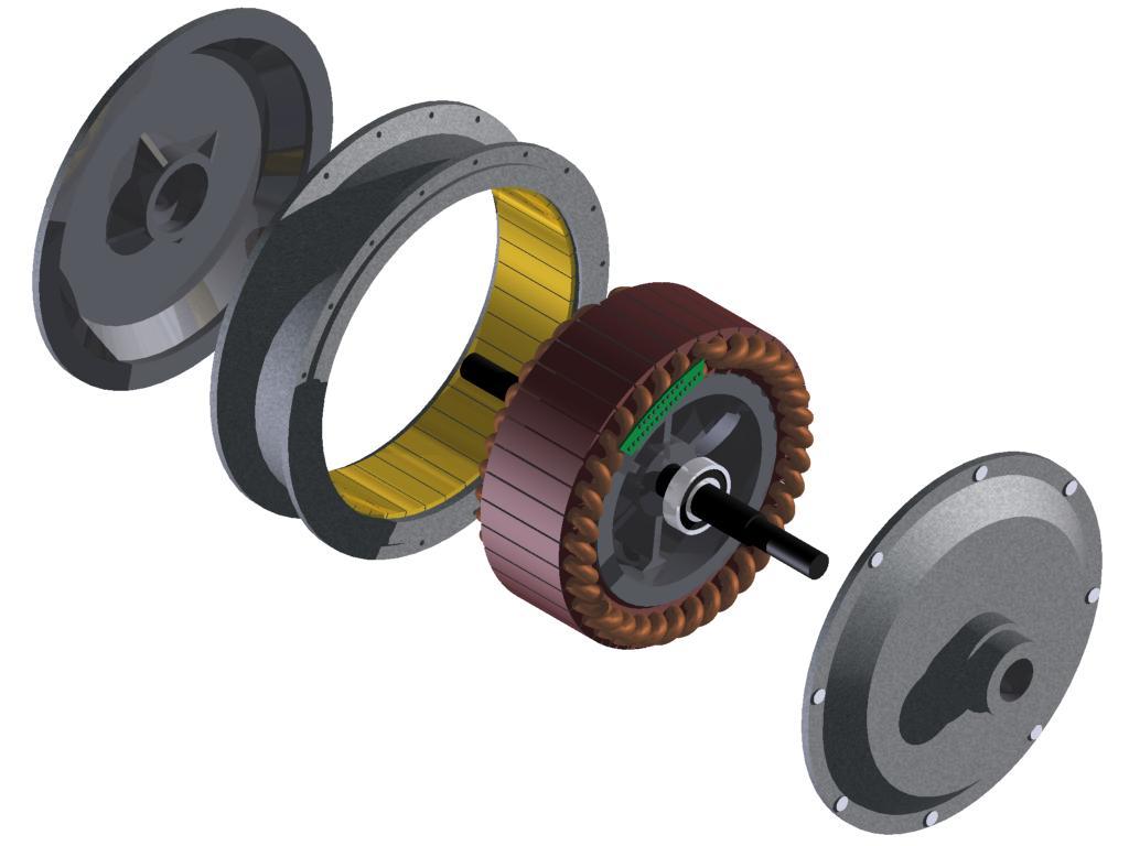
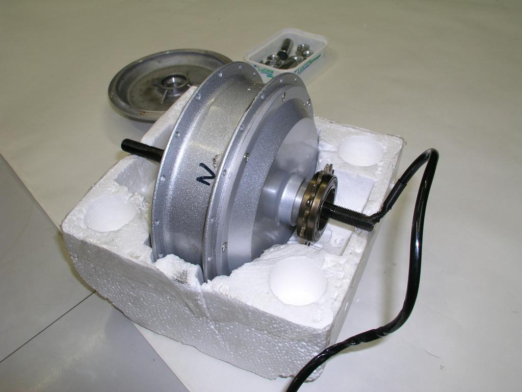
64 Low speed motor with outer rotor - 40 poles on rotor - 36 poles on stator W - 36 V min -1

65 High speed with planet gear to low speed Rotor inside has 4 poles

66 Friction planet gearbox
 P N =450")
67 Planet gearbox with cogs (teeth) P N =450 W
An Introduction to Electrical Machines. P. Di Barba, University of Pavia, Italy
 An Introduction to Electrical Machines P. Di Barba, University of Pavia, Italy Academic year 0-0 Contents Transformer. An overview of the device. Principle of operation of a single-phase transformer 3.
Synchronous Machines
 Synchronous machine 1. Construction Generator Exciter View of a twopole round rotor generator and exciter. A Stator with laminated iron core C Slots with phase winding B A B Rotor with dc winding B N S
Lesson 17: Synchronous Machines
 Lesson 17: Synchronous Machines ET 332b Ac Motors, Generators and Power Systems Lesson 17_et332b.pptx 1 Learning Objectives After this presentation you will be able to: Explain how synchronous machines
ECE 325 Electric Energy System Components 7- Synchronous Machines. Instructor: Kai Sun Fall 2015
 ECE 325 Electric Energy System Components 7- Synchronous Machines Instructor: Kai Sun Fall 2015 1 Content (Materials are from Chapters 16-17) Synchronous Generators Synchronous Motors 2 Synchronous Generators
Chapter 4. Synchronous Generators. Basic Topology
 Basic Topology Chapter 4 ynchronous Generators In stator, a three-phase winding similar to the one described in chapter 4. ince the main voltage is induced in this winding, it is also called armature winding.
Introduction to Synchronous. Machines. Kevin Gaughan
 Introduction to Synchronous Machines Kevin Gaughan The Synchronous Machine An AC machine (generator or motor) with a stator winding (usually 3 phase) generating a rotating magnetic field and a rotor carrying
Synchronous Machines
 Synchronous Machines Synchronous generators or alternators are used to convert mechanical power derived from steam, gas, or hydraulic-turbine to ac electric power Synchronous generators are the primary
Tutorial 1 (EMD) Rotary field winding
 Rotary field winding") Tutorial 1 (EMD) Rotary field winding The unchorded two-layer three-phase winding of a small synchronous fan drive for a computer has the following parameters: number of slots per pole and phase q = 1,
Tutorial 1 (EMD) Rotary field winding The unchorded two-layer three-phase winding of a small synchronous fan drive for a computer has the following parameters: number of slots per pole and phase q = 1,
EE 742 Chapter 3: Power System in the Steady State. Y. Baghzouz
 EE 742 Chapter 3: Power System in the Steady State Y. Baghzouz Transmission Line Model Distributed Parameter Model: Terminal Voltage/Current Relations: Characteristic impedance: Propagation constant: π
Revision Guide for Chapter 15
 Revision Guide for Chapter 15 Contents tudent s Checklist Revision otes Transformer... 4 Electromagnetic induction... 4 Generator... 5 Electric motor... 6 Magnetic field... 8 Magnetic flux... 9 Force on
Massachusetts Institute of Technology Department of Electrical Engineering and Computer Science Electric Machines
 Massachusetts Institute of Technology Department of Electrical Engineering and Computer Science 6.685 Electric Machines Problem Set 10 Issued November 11, 2013 Due November 20, 2013 Problem 1: Permanent
3 d Calculate the product of the motor constant and the pole flux KΦ in this operating point. 2 e Calculate the torque.
 Exam Electrical Machines and Drives (ET4117) 11 November 011 from 14.00 to 17.00. This exam consists of 5 problems on 4 pages. Page 5 can be used to answer problem 4 question b. The number before a question
ROEVER COLLEGE OF ENGINEERING & TECHNOLOGY ELAMBALUR, PERAMBALUR DEPARTMENT OF ELECTRICAL AND ELECTRONICS ENGINEERING ELECTRICAL MACHINES I
 ROEVER COLLEGE OF ENGINEERING & TECHNOLOGY ELAMBALUR, PERAMBALUR-621220 DEPARTMENT OF ELECTRICAL AND ELECTRONICS ENGINEERING ELECTRICAL MACHINES I Unit I Introduction 1. What are the three basic types
Energy Converters. CAD and System Dynamics
 Institut für Elektrische Energiewandlung Energy Converters CAD and System Dynamics - Tutorials - Issue 2017/2018 M.Sc. Sascha Neusüs / M.Sc. Marcel Lehr Professor Dr.-Ing. habil. Dr. h.c. Andreas Binder
Dynamics of the synchronous machine
 ELEC0047 - Power system dynamics, control and stability Dynamics of the synchronous machine Thierry Van Cutsem t.vancutsem@ulg.ac.be www.montefiore.ulg.ac.be/~vct October 2018 1 / 38 Time constants and
MODELING AND HIGH-PERFORMANCE CONTROL OF ELECTRIC MACHINES
 MODELING AND HIGH-PERFORMANCE CONTROL OF ELECTRIC MACHINES JOHN CHIASSON IEEE PRESS ü t SERIES ON POWER ENGINEERING IEEE Press Series on Power Engineering Mohamed E. El-Hawary, Series Editor The Institute
UNIT I INTRODUCTION Part A- Two marks questions
 ROEVER COLLEGE OF ENGINEERING & TECHNOLOGY ELAMBALUR, PERAMBALUR-621220 DEPARTMENT OF ELECTRICAL AND ELECTRONICS ENGINEERING DESIGN OF ELECTRICAL MACHINES UNIT I INTRODUCTION 1. Define specific magnetic
JRE SCHOOL OF Engineering
 JRE SCHOOL OF Engineering Class Test-1 Examinations September 2014 Subject Name Electromechanical Energy Conversion-II Subject Code EEE -501 Roll No. of Student Max Marks 30 Marks Max Duration 1 hour Date
Stepping Motors. Chapter 11 L E L F L D
 Chapter 11 Stepping Motors In the synchronous motor, the combination of sinusoidally distributed windings and sinusoidally time varying current produces a smoothly rotating magnetic field. We can eliminate
NEPTUNE -code: KAUVG11ONC Prerequisites:... Knowledge description:
 Subject name: Electrical Machines Credits: 9 Requirement : Course director: Dr. Vajda István Position: Assessment and verification procedures: NEPTUNE -code: KAUVG11ONC Prerequisites:... Number of hours:
Revision Guide for Chapter 15
 Revision Guide for Chapter 15 Contents Revision Checklist Revision otes Transformer...4 Electromagnetic induction...4 Lenz's law...5 Generator...6 Electric motor...7 Magnetic field...9 Magnetic flux...
ELECTRICALMACHINES-I QUESTUION BANK
 ELECTRICALMACHINES-I QUESTUION BANK UNIT-I INTRODUCTION OF MAGNETIC MATERIAL PART A 1. What are the three basic rotating Electric machines? 2. Name the three materials used in machine manufacture. 3. What
EEE3405 ELECTRICAL ENGINEERING PRINCIPLES 2 - TEST
 ATTEMPT ALL QUESTIONS (EACH QUESTION 20 Marks, FULL MAKS = 60) Given v 1 = 100 sin(100πt+π/6) (i) Find the MS, period and the frequency of v 1 (ii) If v 2 =75sin(100πt-π/10) find V 1, V 2, 2V 1 -V 2 (phasor)
University of Jordan Faculty of Engineering & Technology Electric Power Engineering Department
 University of Jordan Faculty of Engineering & Technology Electric Power Engineering Department EE471: Electrical Machines-II Tutorial # 2: 3-ph Induction Motor/Generator Question #1 A 100 hp, 60-Hz, three-phase
Introduction. Energy is needed in different forms: Light bulbs and heaters need electrical energy Fans and rolling miles need mechanical energy
 Introduction Energy is needed in different forms: Light bulbs and heaters need electrical energy Fans and rolling miles need mechanical energy What does AC and DC stand for? Electrical machines Motors
Electric Machines I Three Phase Induction Motor. Dr. Firas Obeidat
 Electric Machines I Three Phase Induction Motor Dr. Firas Obeidat 1 Table of contents 1 General Principles 2 Construction 3 Production of Rotating Field 4 Why Does the Rotor Rotate 5 The Slip and Rotor
Prince Sattam bin Abdulaziz University College of Engineering. Electrical Engineering Department EE 3360 Electrical Machines (II)
") Chapter # 4 Three-Phase Induction Machines 1- Introduction (General Principles) Generally, conversion of electrical power into mechanical power takes place in the rotating part of an electric motor. In
Chapter # 4 Three-Phase Induction Machines 1- Introduction (General Principles) Generally, conversion of electrical power into mechanical power takes place in the rotating part of an electric motor. In
Gentle synchronization of two-speed synchronous motor with asynchronous starting
 Electr Eng (2012) 94:155 163 DOI 10.1007/s00202-011-0227-1 ORIGINAL PAPER Gentle synchronization of two-speed synchronous motor with asynchronous starting Paweł Zalas Jan Zawilak Received: 5 November 2009
Generators for wind power conversion
 Generators for wind power conversion B. G. Fernandes Department of Electrical Engineering Indian Institute of Technology, Bombay Email : bgf@ee.iitb.ac.in Outline of The Talk Introduction Constant speed
INDUCTION MOTOR MODEL AND PARAMETERS
 APPENDIX C INDUCTION MOTOR MODEL AND PARAMETERS C.1 Dynamic Model of the Induction Motor in Stationary Reference Frame A three phase induction machine can be represented by an equivalent two phase machine
The synchronous machine (detailed model)
") ELEC0029 - Electric Power System Analysis The synchronous machine (detailed model) Thierry Van Cutsem t.vancutsem@ulg.ac.be www.montefiore.ulg.ac.be/~vct February 2018 1 / 6 Objectives The synchronous
ELEC0029 - Electric Power System Analysis The synchronous machine (detailed model) Thierry Van Cutsem t.vancutsem@ulg.ac.be www.montefiore.ulg.ac.be/~vct February 2018 1 / 6 Objectives The synchronous
Equal Pitch and Unequal Pitch:
 Equal Pitch and Unequal Pitch: Equal-Pitch Multiple-Stack Stepper: For each rotor stack, there is a toothed stator segment around it, whose pitch angle is identical to that of the rotor (θs = θr). A stator
DC motors. 1. Parallel (shunt) excited DC motor
 excited DC motor") DC motors 1. Parallel (shunt) excited DC motor A shunt excited DC motor s terminal voltage is 500 V. The armature resistance is 0,5 Ω, field resistance is 250 Ω. On a certain load it takes 20 A current
DC motors 1. Parallel (shunt) excited DC motor A shunt excited DC motor s terminal voltage is 500 V. The armature resistance is 0,5 Ω, field resistance is 250 Ω. On a certain load it takes 20 A current
Motor Info on the WWW Motorola Motors DC motor» /MOTORDCTUT.
 Motor Info on the WWW Motorola Motors DC motor» http://www.freescale.com/files/microcontrollers/doc/train_ref_material /MOTORDCTUT.html Brushless DC motor» http://www.freescale.com/files/microcontrollers/doc/train_ref_material
Vector Controlled Power Generation in a Point Absorber Based Wave Energy Conversion System
 Vector Controlled Power Generation in a Point Absorber Based Wave Energy Conversion System Jisha Thomas Chandy 1 and Mr. Vishnu J 2 1,2 Electrical & Electronics Dept of Engineering, Sree Buddha College
The synchronous machine (SM) in the power system (2) (Where does the electricity come from)?
 in the power system (2) (Where does the electricity come from)?") 1 The synchronous machine (SM) in the power system (2) (Where does the electricity come from)? 2 Lecture overview Synchronous machines with more than 2 magnetic poles The relation between the number of
1 The synchronous machine (SM) in the power system (2) (Where does the electricity come from)? 2 Lecture overview Synchronous machines with more than 2 magnetic poles The relation between the number of
Lezione 9 30 March. Scribes: Arianna Marangon, Matteo Vitturi, Riccardo Prota
 Control Laboratory: a.a. 2015/2016 Lezione 9 30 March Instructor: Luca Schenato Scribes: Arianna Marangon, Matteo Vitturi, Riccardo Prota What is left to do is how to design the low pass pole τ L for the
Generators. What its all about
 Generators What its all about How do we make a generator? Synchronous Operation Rotor Magnetic Field Stator Magnetic Field Forces and Magnetic Fields Force Between Fields Motoring Generators & motors are
Module 3 : Sequence Components and Fault Analysis
 Module 3 : Sequence Components and Fault Analysis Lecture 12 : Sequence Modeling of Power Apparatus Objectives In this lecture we will discuss Per unit calculation and its advantages. Modeling aspects
EC T32 - ELECTRICAL ENGINEERING
 EC T32 - ELECTRICAL ENGINEERING UNIT-I - TRANSFORMER 1. What is a transformer? 2. Briefly explain the principle of operation of transformers. 3. What are the parts of a transformer? 4. What are the types
Equivalent Circuits with Multiple Damper Windings (e.g. Round rotor Machines)
") Equivalent Circuits with Multiple Damper Windings (e.g. Round rotor Machines) d axis: L fd L F - M R fd F L 1d L D - M R 1d D R fd R F e fd e F R 1d R D Subscript Notations: ( ) fd ~ field winding quantities
Equivalent Circuits with Multiple Damper Windings (e.g. Round rotor Machines) d axis: L fd L F - M R fd F L 1d L D - M R 1d D R fd R F e fd e F R 1d R D Subscript Notations: ( ) fd ~ field winding quantities
ECE 421/521 Electric Energy Systems Power Systems Analysis I 3 Generators, Transformers and the Per-Unit System. Instructor: Kai Sun Fall 2013
 ECE 41/51 Electric Energy Systems Power Systems Analysis I 3 Generators, Transformers and the Per-Unit System Instructor: Kai Sun Fall 013 1 Outline Synchronous Generators Power Transformers The Per-Unit
LESSON 20 ALTERNATOR OPERATION OF SYNCHRONOUS MACHINES
 ET 332b Ac Motors, Generators and Power Systems LESSON 20 ALTERNATOR OPERATION OF SYNCHRONOUS MACHINES 1 LEARNING OBJECTIVES After this presentation you will be able to: Interpret alternator phasor diagrams
Definition Application of electrical machines Electromagnetism: review Analogies between electric and magnetic circuits Faraday s Law Electromagnetic
 Definition Application of electrical machines Electromagnetism: review Analogies between electric and magnetic circuits Faraday s Law Electromagnetic Force Motor action Generator action Types and parts
Synchronous machine with PM excitation Two-axis model
 Synchronous machine with PM excitation q Two-axis model q i q u q d i Q d Q D i d N S i D u d Voltage, flux-linkage and motion equations for a PM synchronous machine dd ud Ri s d q dt dq uq Ri s q d dt
Control of Wind Turbine Generators. James Cale Guest Lecturer EE 566, Fall Semester 2014 Colorado State University
 Control of Wind Turbine Generators James Cale Guest Lecturer EE 566, Fall Semester 2014 Colorado State University Review from Day 1 Review Last time, we started with basic concepts from physics such as
Electrical Machines and Energy Systems: Operating Principles (Part 2) SYED A Rizvi
 SYED A Rizvi") Electrical Machines and Energy Systems: Operating Principles (Part 2) SYED A Rizvi AC Machines Operating Principles: Synchronous Motor In synchronous motors, the stator of the motor has a rotating magnetic
Electrical Machines and Energy Systems: Operating Principles (Part 2) SYED A Rizvi AC Machines Operating Principles: Synchronous Motor In synchronous motors, the stator of the motor has a rotating magnetic
Doubly salient reluctance machine or, as it is also called, switched reluctance machine. [Pyrhönen et al 2008]
![Doubly salient reluctance machine or, as it is also called, switched reluctance machine. [Pyrhönen et al 2008]](/thumbs/86/93665357.jpg "Doubly salient reluctance machine or, as it is also called, switched reluctance machine. [Pyrhönen et al 2008]") Doubly salient reluctance machine or, as it is also called, switched reluctance machine [Pyrhönen et al 2008] Pros and contras of a switched reluctance machine Advantages Simple robust rotor with a small
Doubly salient reluctance machine or, as it is also called, switched reluctance machine [Pyrhönen et al 2008] Pros and contras of a switched reluctance machine Advantages Simple robust rotor with a small
Chapter 5 Three phase induction machine (1) Shengnan Li
 Shengnan Li") Chapter 5 Three phase induction machine (1) Shengnan Li Main content Structure of three phase induction motor Operating principle of three phase induction motor Rotating magnetic field Graphical representation
Chapter 5 Three phase induction machine (1) Shengnan Li Main content Structure of three phase induction motor Operating principle of three phase induction motor Rotating magnetic field Graphical representation
Power density improvement of three phase flux reversal machine with distributed winding
 Published in IET Electric Power Applications Received on 4th January 2009 Revised on 2nd April 2009 ISSN 1751-8660 Power density improvement of three phase flux reversal machine with distributed winding
Chapter 6. Induction Motors. Copyright The McGraw-Hill Companies, Inc. Permission required for reproduction or display.
 Chapter 6 Induction Motors 1 The Development of Induced Torque in an Induction Motor Figure 6-6 The development of induced torque in an induction motor. (a) The rotating stator field B S induces a voltage
SECTION - I. PULL-IN-OPERATION Op SYNCHRONOUS MOTORS
 SECTION - I PULL-IN-OPERATION Op SYNCHRONOUS MOTORS 14 S 1.1 INTRODUCTION The starting of synchronous, reluctance and permanent magnet synchronous motors is normally carried out by damper winding. The
Time-Harmonic Modeling of Squirrel-Cage Induction Motors: A Circuit-Field Coupled Approach
 Time-Harmonic Modeling of Squirrel-Cage Induction Motors: A Circuit-Field Coupled Approach R. Escarela-Perez 1,3 E. Melgoza 2 E. Campero-Littlewood 1 1 División de Ciencias Básicas e Ingeniería, Universidad
1439. Numerical simulation of the magnetic field and electromagnetic vibration analysis of the AC permanent-magnet synchronous motor
 1439. Numerical simulation of the magnetic field and electromagnetic vibration analysis of the AC permanent-magnet synchronous motor Bai-zhou Li 1, Yu Wang 2, Qi-chang Zhang 3 1, 2, 3 School of Mechanical
Texas A & M University Department of Mechanical Engineering MEEN 364 Dynamic Systems and Controls Dr. Alexander G. Parlos
 Texas A & M University Department of Mechanical Engineering MEEN 364 Dynamic Systems and Controls Dr. Alexander G. Parlos Lecture 6: Modeling of Electromechanical Systems Principles of Motor Operation
ELECTRIC MACHINE TORQUE PRODUCTION 101
 ELECTRIC MACHINE TORQUE PRODUCTION 101 Best Electric Machine, 014 INTRODUCTION: The following discussion will show that the symmetrical (or true dual-ported) transformer electric machine as only provided
AC Induction Motor Stator Resistance Estimation Algorithm
 7th WSEAS International Conference on Electric Power Systems, High Voltages, Electric Machines, Venice, Italy, November 21-23, 27 86 AC Induction Motor Stator Resistance Estimation Algorithm PETR BLAHA
Selection of precision micro drives
 Selection of precision micro drives Overview Drive System and Selection DC and EC motors Motor data sheets, motor theory Motor gearhead selection 2017 maxon motor ag, Sachseln, Switzerland Media The Selection
Behaviour of synchronous machine during a short-circuit (a simple example of electromagnetic transients)
") ELEC0047 - Power system dynamics, control and stability (a simple example of electromagnetic transients) Thierry Van Cutsem t.vancutsem@ulg.ac.be www.montefiore.ulg.ac.be/~vct October 2018 1 / 25 Objectives
ELEC0047 - Power system dynamics, control and stability (a simple example of electromagnetic transients) Thierry Van Cutsem t.vancutsem@ulg.ac.be www.montefiore.ulg.ac.be/~vct October 2018 1 / 25 Objectives
Selection of precision micro drives
 Selection of precision micro drives Systematics of the drive selection Situation analysis, boundary conditions How is the integration into the environment? Preselection Determining the load requirements
Tutorial Sheet Fig. Q1
 Tutorial Sheet - 04 1. The magnetic circuit shown in Fig. Q1 has dimensions A c = A g = 9 cm 2, g = 0.050 cm, l c = 30 cm, and N = 500 turns. Assume the value of the relative permeability,µ r = 70,000
Automatic Control Systems. -Lecture Note 15-
 -Lecture Note 15- Modeling of Physical Systems 5 1/52 AC Motors AC Motors Classification i) Induction Motor (Asynchronous Motor) ii) Synchronous Motor 2/52 Advantages of AC Motors i) Cost-effective ii)
CPPM Mahine: A Synchronous Permanent Magnet Machine with Field Weakening
 CPPM Mahine: A Synchronous Permanent Magnet Machine with Field Weakening Juan A. Tapia, Thomas A. Lipo, Fellow, IEEE Dept. of Electrical and Computer Engineering University of Wisconsin-Madison 45 Engineering
6 Chapter 6 Testing and Evaluation
 6 Chapter 6 Testing and Evaluation n this chapter the results obtained during the testing of the LS PMSM prototype are provided. The test results are compared with Weg s LS PMSM machine, WQuattro. The
Chapter 3 AUTOMATIC VOLTAGE CONTROL
 Chapter 3 AUTOMATIC VOLTAGE CONTROL . INTRODUCTION TO EXCITATION SYSTEM The basic function of an excitation system is to provide direct current to the field winding of the synchronous generator. The excitation
Analytical Model for Sizing the Magnets of Permanent Magnet Synchronous Machines
 Journal of Electrical Engineering 3 (2015) 134-141 doi: 10.17265/2328-2223/2015.03.004 D DAVID PUBLISHING Analytical Model for Sizing Magnets of Permanent Magnet Synchronous Machines George Todorov and
Generalized Theory of Electrical Machines- A Review
 Generalized Theory of Electrical Machines- A Review Dr. Sandip Mehta Department of Electrical and Electronics Engineering, JIET Group of Institutions, Jodhpur Abstract:-This paper provides an overview
Modeling and Testing of the Multi-pole Field of a Motor for Pure Electric Vehicles
 Automotive Innovation (2018 1:226 236 https://doi.org/10.1007/s42154-018-0025-9 Modeling and Testing of the Multi-pole Field of a Motor for Pure Electric Vehicles Dongchen Qin 1 Lei Cheng 1 Tingting Wang
ON THE PARAMETERS COMPUTATION OF A SINGLE SIDED TRANSVERSE FLUX MOTOR
 ON THE PARAMETERS COMPUTATION OF A SINGLE SIDED TRANSVERSE FLUX MOTOR Henneberger, G. 1 Viorel, I. A. Blissenbach, R. 1 Popan, A.D. 1 Department of Electrical Machines, RWTH Aachen, Schinkelstrasse 4,
Mutual Inductance. The field lines flow from a + charge to a - change
 Capacitors Mutual Inductance Since electrical charges do exist, electric field lines have a starting point and an ending point. For example, if you have a + and a - change, the field lines would look something
Modeling Free Acceleration of a Salient Synchronous Machine Using Two-Axis Theory
 1 Modeling ree Acceleration of a Salient Synchronous Machine Using Two-Axis Theory Abdullah H. Akca and Lingling an, Senior Member, IEEE Abstract This paper investigates a nonlinear simulation model of
Proposal of short armature core double-sided transverse flux type linear synchronous motor
 Proposal of short armature core double-sided transverse flux type linear synchronous motor Shin Jung-Seob a, Takafumi Koseki a and Kim Houng-Joong b a The University of Tokyo, Engineering Building #2 12F,7-3-1
PHASOR DIAGRAM OF TRANSFORMER. Prepared By ELECTRICALBABA.COM
 PHASOR DIAGRAM OF TRANSFORMER Prepared By ELECTRICALBABA.COM IMPORTANT POINTS FOR PHASOR OF TRANSFORMER Transformer when excited at no load, only takes excitation current which leads the working Flux by
8 z 2, then the greatest value of z is. 2. The principal argument/amplitude of the complex number 1 2 i (C) (D) 3 (C)
 (D) 3 (C)") 1. If z is a complex number and if 8 z 2, then the greatest value of z is z (A) 2 (B) 3 (C) 4 (D) 5 4 2. The principal argument/amplitude of the complex number 1 2 i 1 3i is (A) 2 (B) 4 (C) (D) 3 4 3.
1. If z is a complex number and if 8 z 2, then the greatest value of z is z (A) 2 (B) 3 (C) 4 (D) 5 4 2. The principal argument/amplitude of the complex number 1 2 i 1 3i is (A) 2 (B) 4 (C) (D) 3 4 3.
CHAPTER 3 INFLUENCE OF STATOR SLOT-SHAPE ON THE ENERGY CONSERVATION ASSOCIATED WITH THE SUBMERSIBLE INDUCTION MOTORS
 38 CHAPTER 3 INFLUENCE OF STATOR SLOT-SHAPE ON THE ENERGY CONSERVATION ASSOCIATED WITH THE SUBMERSIBLE INDUCTION MOTORS 3.1 INTRODUCTION The electric submersible-pump unit consists of a pump, powered by
SECOND ENGINEER REG III/2 MARINE ELECTRO-TECHNOLOGY. 1. Understands the physical construction and characteristics of basic components.
 SECOND ENGINEER REG III/ MARINE ELECTRO-TECHNOLOGY LIST OF TOPICS A B C D Electric and Electronic Components Electric Circuit Principles Electromagnetism Electrical Machines The expected learning outcome
Design and Characteristic Analysis of LSM for High Speed Train System using Magnetic Equivalent Circuit
 IJR International Journal of Railway Vol. 3, No. 1 / March 2010, pp. 14-18 The Korean Society for Railway Design and Characteristic Analysis of LSM for High Speed Train System using Magnetic Equivalent
MAHARASHTRA STATE BOARD OF TECHNICAL EDUCATION
 Important Instructions to examiners: 1) The answers should be examined by key words and not as word-to-word as given in the model answer scheme. 2) The model answer and the answer written by candidate
Analytical and Numerical Calculations of Synchronous Motors for Industrial Drives
 014 UKSim-AMSS 8th European Modelling Symposium Analytical and Numerical Calculations of Synchronous Motors for Industrial Drives Iossif Grinbaum ABB Switzerland Ltd., Segelhofstrasse 9P 5405 Baden-Dättwil,
Induction Motors. The single-phase induction motor is the most frequently used motor in the world
 Induction Motor The single-phase induction motor is the most frequently used motor in the world Most appliances, such as washing machines and refrigerators, use a single-phase induction machine Highly
Influence of different rotor magnetic circuit structure on the performance. permanent magnet synchronous motor
 ARCHIVES OF ELECTRICAL ENGINEERING VOL. 66(3), pp. 583-594 (2017) DOI 10.1515/aee-2017-0044 Influence of different rotor magnetic circuit structure on the performance of permanent magnet synchronous motor
Mathematical Modeling and Dynamic Simulation of a Class of Drive Systems with Permanent Magnet Synchronous Motors
 Applied and Computational Mechanics 3 (2009) 331 338 Mathematical Modeling and Dynamic Simulation of a Class of Drive Systems with Permanent Magnet Synchronous Motors M. Mikhov a, a Faculty of Automatics,
Parameter Estimation of Three Phase Squirrel Cage Induction Motor
 International Conference On Emerging Trends in Mechanical and Electrical Engineering RESEARCH ARTICLE OPEN ACCESS Parameter Estimation of Three Phase Squirrel Cage Induction Motor Sonakshi Gupta Department
Flux: Examples of Devices
 Flux: Examples of Devices xxx Philippe Wendling philippe.wendling@magsoft-flux.com Create, Design, Engineer! www.magsoft-flux.com www.cedrat.com Solenoid 2 1 The Domain Axisymmetry Open Boundary 3 Mesh
R13 SET Derive the expression for the maximum bending stress developed in the leaf spring and also the central deflection of a leaf spring.
 Code No: RT22013 R13 SET - 41 STRENGTH OF MATERIALS - II (Civil Engineering) Time: 3 hours Max. Marks: 70 Note: 1. Question Paper consists of two parts (Part-A and Part-B) 2. Answer ALL the question in
Finite Element Analysis of Hybrid Excitation Axial Flux Machine for Electric Cars
 223 Finite Element Analysis of Hybrid Excitation Axial Flux Machine for Electric Cars Pelizari, A. ademir.pelizari@usp.br- University of Sao Paulo Chabu, I.E. ichabu@pea.usp.br - University of Sao Paulo
Electromagnetics and Electric Machines Stefan Holst, CD-adapco
 Electromagnetics and Electric Machines Stefan Holst, CD-adapco Overview Electric machines intro Designing electric machines with SPEED Links to STAR-CCM+ for thermal modeling Electromagnetics in STAR-CCM+
Abstract The capability (P-Q) curve of generator can be determined only on the base of examinations in the power plant, i.e. on the base of: the no-lo
 curve of generator can be determined only on the base of examinations in the power plant, i.e. on the base of: the no-lo") CONSTRUCTION OF GENERATOR CAPABILITY CURVES USING THE NEW METHOD FOR DETERMINATION OF POTIER REACTANCE M.M. Kostić*, M. Ivanović*, B. Kostić*, S. Ilić** and D. Ćirić** Electrical Engineering Institute
CONSTRUCTION OF GENERATOR CAPABILITY CURVES USING THE NEW METHOD FOR DETERMINATION OF POTIER REACTANCE M.M. Kostić*, M. Ivanović*, B. Kostić*, S. Ilić** and D. Ćirić** Electrical Engineering Institute
ECEN 667 Power System Stability Lecture 11: Exciter Models
 CN 667 Power System Stability Lecture : xciter Models Prof. Tom Overbye Dept. of lectrical and Computer ngineering Texas A&M University, overbye@tamu.edu Announcements Read Chapter 4 Homework 3 is due
EE 410/510: Electromechanical Systems Chapter 4
 EE 410/510: Electromechanical Systems Chapter 4 Chapter 4. Direct Current Electric Machines and Motion Devices Permanent Magnet DC Electric Machines Radial Topology Simulation and Experimental Studies
Step Motor Modeling. Step Motor Modeling K. Craig 1
 Step Motor Modeling Step Motor Modeling K. Craig 1 Stepper Motor Models Under steady operation at low speeds, we usually do not need to differentiate between VR motors and PM motors (a hybrid motor is
PROPOSAL FOR ADDITION OF IEC 34-4 STANDARD IN PART FOR DETERMINATION OF POTIER REACTANCE
 PROPOSAL FOR ADDITION OF IEC 34-4 STANDARD IN PART FOR DETERMINATION OF POTIER REACTANCE M. M. Kostic * Electrical Engeneering Institute Nikola Tesla, Belgrade, SERBIA* Abstract: On the base of ones investigations
د شوقي حامد عرفه ابراهيم
 2015 /1/19 اإلجابة النموذجية لمادة نظم التشغيل الكهربية ك 563 د شوقي حامد عرفه ابراهيم يوم االثنين الموافق Benha University Benha Faculty of Engineering Subject: Electrical drives (E563) Time: 3hours Fifth
Lecture 12. Time Varying Electromagnetic Fields
 Lecture. Time Varying Electromagnetic Fields For static electric and magnetic fields: D = ρ () E = 0...( ) D= εe B = 0...( 3) H = J H = B µ...( 4 ) For a conducting medium J =σ E From Faraday s observations,
Electrical Machines and Energy Systems: Operating Principles (Part 1) SYED A Rizvi
 SYED A Rizvi") Electrical Machines and Energy Systems: Operating Principles (Part 1) SYED A Rizvi AC Machines Operating Principles: Rotating Magnetic Field The key to the functioning of AC machines is the rotating magnetic
Electrical Machines and Energy Systems: Operating Principles (Part 1) SYED A Rizvi AC Machines Operating Principles: Rotating Magnetic Field The key to the functioning of AC machines is the rotating magnetic
Analytical and numerical computation of the no-load magnetic field in induction motors
 Analytical and numerical computation of the no-load induction motors Dan M. Ionel University of Glasgow, Glasgow, Scotland, UK and Mihai V. Cistelecan Research Institute for Electrical Machines, Bucharest
CHAPTER 5 SIMULATION AND TEST SETUP FOR FAULT ANALYSIS
 47 CHAPTER 5 SIMULATION AND TEST SETUP FOR FAULT ANALYSIS 5.1 INTRODUCTION This chapter describes the simulation model and experimental set up used for the fault analysis. For the simulation set up, the
AN EFFICIENT APPROACH FOR ANALYSIS OF ISOLATED SELF EXCITED INDUCTION GENERATOR
 AN EFFICIENT APPROACH FOR ANALYSIS OF ISOLATED SELF EXCITED INDUCTION GENERATOR Deepika 1, Pankaj Mehara Assistant Professor, Dept. of EE, DCRUST, Murthal, India 1 PG Student, Dept. of EE, DCRUST, Murthal,
CHAPTER 4 DESIGN OF GRID CONNECTED INDUCTION GENERATORS FOR CONSTANT SPEED WIND POWER GENERATION
 CHAPTER 4 DESIGN OF GRID CONNECTED INDUCTION GENERATORS FOR CONSTANT SPEED WIND POWER GENERATION 4.1 Introduction For constant shaft speed grid-connected wind energy conversion systems, the squirrel cage
ECEN 667 Power System Stability Lecture 18: Voltage Stability, Load Models
 ECEN 667 Power System Stability Lecture 18: Voltage Stability, Load Models Prof. Tom Overbye Dept. of Electrical and Computer Engineering Texas A&M University, overbye@tamu.edu 1 Announcements Read Chapter