ECE 422/522 Power System Operations & Planning/ Power Systems Analysis II 2 Synchronous Machine Modeling
|
|
|
- Piers Walker
- 5 years ago
- Views:
Transcription
1 ECE 422/522 Power System Operations & Planning/ Power Systems Analysis II 2 Synchronous achine odeling Spring 214 Instructor: Kai Sun 1
2 Outline Synchronous achine odeling Per Unit Representation Simplified odels for Stability Studies 2


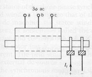
3 Synchronous Generators Salient-pole rotor Cylindrical/round rotor Field winding Armature winding Stator Field current 3
 Have damper/amortisseur windings to help damp out speed oscillations Round rotors 7% of large synchronous generators (15~15VA) Distributed winding and uniform")
 Round rotor generator under construction (Source: http://emadrlc.")
4 Types of Rotors Salient pole rotors Concentrated windings on poles and nonuniform air gap Short axial length and large diameter Hydraulic turbines operated at low speeds (large number of poles) Have damper/amortisseur windings to help damp out speed oscillations Round rotors 7% of large synchronous generators (15~15VA) Distributed winding and uniform air gap Large axial length and small diameter to limit the centrifugal forces Steam and gas turbines, operated at high speeds, typically 36 or 18rpm (2 or 4-pole) No special damper windings but eddy in the solid steal rotor gives damping effects 4 16 poles salient-pole rotor (12 W) Round rotor generator under construction (Source:
5 Generator odel d F r n Flux linkage with coil a (leading the axis of a by ωt) ψa Nφcosωt Induced voltage: dψ a ea ωnφsinωt Emax sinωt dt (reaches the maximum at the current position) f P n 2 6 (n: synchronous speed in rpm; P: the number of poles) m N S γ γ F s e a Axis of coil a (reference) Assume: i a is lagging e a by γ (i a reaches the maximum when mn aligns with aa ) 2 4 ia Imax sin( ωt γ) ib Imax sin( ωt γ π) ic Imax sin( ωt γ π) 3 3 agnetic motive forces (F s) of three phases: F Ki F sin( ωt γ) a a m 2 Fb Kib Fmsin( ωt γ π) 3 4 Fc Kic Fmsin( ωt γ π) 3 F s 3 2 F m F s is orthogonal to mn and revolving synchronously with F F r due to the rotor 5
6 Under Steady-State Conditions F r + F s gives F F sr in air gap F s induces EF E ar F sr results air gap flux φ sr to induce EF N γ d F r F sr n Axis of coil a E sr E a +E ar For a round rotor, define the reactance of the armature reaction X ar -E ar /(ji a ) Terminal voltage V, resistance R a and leakage and reactance X l satisfy m S γ e a F s (reference) E V + [ R + j( X + X )] I V + ( R + jx ) I a a ar a a s a F r X s X l +X ar is known as the synchronous reactance F sr γ E a E a Load E sr E ar F s 6
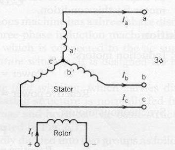
7 Stator and Rotor Windings Armature windings: a-a, b-b and c-c windings Rotor windings: Field windings Field winding F-F produces a flux on the d-axis. Damper windings Two damper windings D-D and Q-Q respectively on d- and q-axes For a round-rotor machine, consider a second damper winding G-G on the q-axis (two windings on each axis) Total number of windings: Salient pole: 3+3 (discussed here) Round-rotor: 3+4 ANSI/IEEE standard : the quadrature (q) axis is defined to lead the d-axis by 9 7

 Stator mutual inductances (l ab, l bc, l ac ) Stator-to-rotor mutual inductances (l af, l bd, l aq ) Rotor self-inductances (l FF, l DD, l QQ ) Rotor mutual inductances (l FD, l DQ, l FQ ) ψ aaa ψ")
8 Winding Circuits Note: we define opposite directions for the current and flux Equations on the EF (electromotive force) and flux of each winding e a dψ a /dt R a i a ψ Q F ψ F ψ a l aa i a l aa i b l aa i c + l aa i F + l aa i D + l aa i Q ψ D e F dψ F /dt + R F i F ψ F l Fa i a l Fb i b l Fc i c + l FF i F + l FD i D + l FQ i Q ψ a ψ b ψ c ψ F ψ D ψ Q l aa l aa l aa l aa l aa l aa l bb l bb l bb l bb l bb l bb l cc l cc l cc l cf l cd l cq l FF l FF l FF l FF l FF l FF l DD l DD l DD l DD l DD l DD l QQ l QQ l QQ l QQ l QQ l QQ i a i b i c i F i D iq Stator self-inductances (l aa, l bb, l cc ) Stator mutual inductances (l ab, l bc, l ac ) Stator-to-rotor mutual inductances (l af, l bd, l aq ) Rotor self-inductances (l FF, l DD, l QQ ) Rotor mutual inductances (l FD, l DQ, l FQ ) ψ aaa ψ FFF L SS L SS L RR L RR i aaa i FFF ost of the efforts in synchronous machine modeling is to find constants and make the EF and flux equations be simpler 8
9 ψ a ψ b ψ c ψ F ψ D ψ Q l aa l aa l aa l aa l aa l aa l bb l bb l bb l bb l bb l bb l cc l cc l cc l bb l bb l bb l FF l FF l FF l FF l FF l FF l DD l DD l DD l DD l DD l DD l QQ l QQ l QQ l QQ l QQ l QQ i a i b i c i F i D iq Wb Turns The matrix is symmetric because the mutual inductance by definition is the flux linkage with one winding per unit current in the other winding, i.e. N x ~ turns of winding x l xy N x Φ my / i y N x N y P xy l yx Φ my ~ mutual flux linking windings x and y due to current in winding y P xy ~ permeance of the mutual flux path A salient pole machine has significantly different permeances in d and q axes, such that the P xy involving a stator winding (e.g. P ab and P af ) is a function of the rotor position α and reaches the maximum twice during o ~36 o P xy P +P 2 cos2α It is advisable to consider d- and q-axis components of P xy individually 9

 l gaa N a i a ( P d+pq 2 + P d P q 2 N a Φ gaa /i a N 2 a( P d+pq 2 L g + L m cos2θ cos2θ) + P d P q 2 cos2θ) 1 Add the leakage inductance: l aa l al + l gaa L al +")
10 Stator self-inductances (l aa, l bb, l cc ) l aa is equal to the ratio of flux linking phase a winding to current i a, with zero currents in all other circuits, and an be approximated as l aa L aa + L aa2 cos2θ Detailed calculation: F a has a sinusoidal distribution in space with its peak centered on phase a axis. Resolve F a into two Fs centered on d and q axes F ad has peak N a i a cosθ F aq has peak -N a i a sinθ Air-gap fluxes Φ gad (N a i a cosθ)p d Φ gaq (-N a i a sinθ)p q Φ gaa Φ gad cosθ - Φ gaq sinθ N a i a (P d cos 2 θ + P q sin 2 θ) l gaa N a i a ( P d+pq 2 + P d P q 2 N a Φ gaa /i a N 2 a( P d+pq 2 L g + L m cos2θ cos2θ) + P d P q 2 cos2θ) 1 Add the leakage inductance: l aa l al + l gaa L al + L g + L m cos2θ L s + L m cos2θ L s >L m l aa L s + L m cos2θ l bb L s + L m cos2(θ-2π/3) l cc L s + L m cos2(θ+2π/3)
 - Φ gaq sin(θ-2π/3) N a i a [P d cosθcos(θ-2π/3)+p q sinθsin(θ-2π/3)] b c a N a i a [ - P d+pq 4 + P d P q cos(2θ-2π/3)] 2 l gba N a Φ gba")
11 Stator utual Inductances (l ab, l bc, l ac ) l ab < since windings a and b have12 o (>9 o ) displacement b q a Has the maximum absolute value when θ -3 or 15. S N θ -3 o d Detailed calculation: Φ gba Φ gad cos(θ-2π/3) - Φ gaq sin(θ-2π/3) N a i a [P d cosθcos(θ-2π/3)+p q sinθsin(θ-2π/3)] b c a N a i a [ - P d+pq 4 + P d P q cos(2θ-2π/3)] 2 l gba N a Φ gba /i a -L g /2 + L m cos(2θ-2π/3) d N θ15 o S q Add leakage flux: c l ab l ba s L s /2 L al - L g /2 + L m cos(2θ-2π/3) - s + L m cos(2θ-2π/3) - s - L m cos2(θ+π/6) l ab - s - L m cos2(θ+π/6) l bc - s - L m cos2(θ-π/2) l ca - s - L m cos2(θ+5π/6) 11
 θ d (F, D) a When the flux linking a stator winding and a rotor winding reaches the")
 l ad l Da D cosθ l bd l Db D cos(θ-2π/3) l cd l Dc D cos(θ+2π/3) q-axis l aq l Qa - Q sinθ l bq l Qb - Q sin(θ-2π/3) l cq l Qc - Q")
12 Stator to Rotor utual Inductances (l af, l bf, l cf, l ad, l bd, l cd, l aq, l bq, l cq ) The rotor sees a constant permeance if neglecting variations in the air gap due to stator slots b q (Q) θ d (F, D) a When the flux linking a stator winding and a rotor winding reaches the maximum when they aligns with each other and is when they are displaced by 9 o c d-axis l af l Fa F cosθ l bf l Fb F cos(θ-2π/3) l cf l Fc F cos(θ+2π/3) l ad l Da D cosθ l bd l Db D cos(θ-2π/3) l cd l Dc D cos(θ+2π/3) q-axis l aq l Qa - Q sinθ l bq l Qb - Q sin(θ-2π/3) l cq l Qc - Q sin(θ+2π/3) 12
13 For Salient-pole Rotors Which of the curves will be different for round rotors? 13 No 2 nd harmonic

14 Rotor Inductances (l FF, l DD, l QQ, l FD, l FQ, l DQ ) They are all constant Rotor self inductances l FF L F l DD L D l QQ L Q Rotor mutual inductances l FD l DF R l FQ l QF l DQ l QD 14
15 Summary ψ aaa ψ FFF L SS L SS L RR L RR i aaa i FFF L RS L T SR L RR L F R R L D L Q What if we define q-axis lagging d-axis by 9 o? Only L RR is constant L SS and L SR are θ or time dependent How to simplify L SS and L SR? Diagonalize L SS Remove time dependency 15
16 Observations ψ aaa ψ FFF L SS L SS L RR L RR i aaa i FFF All harmonic terms in L SS (1 st harmonic) and L SR (2 nd harmonic) are due to the rotor rotating relative to a, b and c to cause variations in permeance Constant L RR doesn t have harmonic terms because it is in a reference frame rotating with the rotor ψ FDQ - L SR i abc + L RR i FDQ L SR i abc -ψ FDQ + L RR i FDQ L SR i abc may be represented by functions independent of θ Represent stator currents and flux linkages also in a reference frame rotating with the rotor. 16
17 ψ FDQ - L SR i abc + L RR i FDQ ψ F -l af i a - l bf i b l cf i c +l FF i F + l FD i D + l FQ i Q - F cosθ i a F cos(θ-2π/3) i b F cos(θ+2π/3)i c +L F i F + R i D + - F [i a cosθ + i b cos(θ-2π/3) + i c cos(θ+2π/3)] + L F i F + R i D K 1 i d ψ D -l ad i a - l bd i b l cd i c +l DF i F + l DD i D + l DQ i Q - D cosθ i a - D cos(θ-2π/3) i b - D cos(θ+2π/3)i c + R i F + L D i D + - D [i a cosθ + i b cos(θ-2π/3) + i c cos(θ+2π/3)] + R i F + L D i D K 2 i d ψ Q -l aq i a - l bq i b l cq i c +l QF i F + l QD i D + l QQ i Q Q sinθ i a + Q sin(θ-2π/3) i b + Q sin(θ+2π/3) i c L Q i Q Q [i a sinθ + i b sin(θ-2π/3) + i c sin(θ+2π/3) ] +L Q i Q K 3 i q 17
18 Park s (dq) Transformation Define For balanced steady-state conditions: i a I m sinω s t i b I m sin(ω s t - 2π/3) i c I m sin(ω s t + 2π/3) i d k d [i a cosθ +i b cos(θ-2π/3) +i c cos(θ+2π/3)] i d k d I m sin(ω s t-θ) 3/2 i q - k g [i a sinθ +i b sin(θ-2π/3) +i c sin(θ+2π/3) ] i q -k q I m cos(ω s t-θ) 3/2 θω r t+θ, ω r ω s Define i k (i a + i b + i c ) i d -k d I m sinθ 3/2 i q -k q I m cosθ 3/2 Constant What if we define q-axis lagging d-axis by 9 o? 18
19 Park s Transformation atrix - P ψ aaa ψ FFF L SS L SS L RR L RR i aaa i FFF ψ dq P ψ abc i dq P i abc ψ ddd ψ FFF LL SS LL SS LL RR L RR i ddd i FFF We hope L RS (L SR ) T like L RS (L SR ) T L RS L RS P -1 L T SR P -1 (P -T L SR ) T (L SR ) T (P L SR ) T P -T P or P T PI (P is a unitary matrix) k d k q 2 3 and k
20 Flux Equations after Park s Transformation ψ d ψ q ψ ψ F ψ D ψ Q L d k F k D L q k Q L k F L F R k D R L D k Q L Q i d i q i i F i D i Q k 3 2 L d L s + s + 3L m /2 L q L s + s - 3L m /2 L L s - 2 s ψ ψ d ψ F ψ D ψ q ψ Q L L d k F k D k F L F R k D R L D L q k Q k Q L Q i i d i F i D i q i Q 2
21 Voltage Equations edψ/dt ± R i Stator: ψ and i are in opposite directions Rotor: ψ and i are the same directions ea en ψ a Ra ia e b e ψ b Rb i n b e c e ψ n c R c i c + ef ψ F RF if ed ψ D R D i D eq ψ Q RQ iq e aaa e FFF R aaa R FFF i aaa i FFF + ψ aaa ψ FFF + e n (A neutral line is added compared to slide #8) Neutral line: e n 1 Rn Rn Rn ia Ln Ln Ln ia di n d e e n ( Rnin Ln )1 Rn Rn R n i b Ln Ln L n i n + b dt dt e n 1 Rn Rn R n i c Ln Ln L n i c d Ri n abc Ln iabc dt 21
22 e aaa e FFF R aaa R FFF i aaa i FFF + ψ aaa ψ FFF + e n Assume R a R b R c ψ dq P ψ abc i dq P i abc 22
23 P ψ aaa ψ ddd d Pψ aaa dd P ψ aaa + Pψ aaap P 1 ψ ddd + Pψ aaa θω r t+θ 23
24 Transformer voltages due to flux change in time ( under steady-state conditions) Speed voltages due to flux change in space S ω r ψ q ω r ψ d ω r ( L q i q + k Q i Q ) ω r ( L d i d + k F i F + k D i D ) ωrl q ( i q ) ω r k Q i Q ω r L d ( i d ) + ω r k F i F + ω r k D i D ) 24
25 P e n P e n P ( -R n i abc - L n di abc /dt ) -P R n P -1 P i abc - P L n P -1 P di abc /dt -P R n P -1 i dq - P L n P -1 (di dq /dt dp/dt i abc ) PR P n PL P 3R n 3L n 1 1 n Note: P L n P -1 dp/dt i abc Pen 3Ri n d 3Ln i d ndq R L n n R R R n n n Rn Rn R n Rn Rn R n L L L n n n Ln Ln L n L L L n n n 25
26 e ddd e FFF R R R i ddd i FFF + ψ ddd ψ FFF + S + n ddd e e d ef e D eq e Q R a + 3R n R a R F R D R a R Q i i d i F i D i q i Q ω r L q ω r k Q ω r L d ω r k F ω r k D + L + 3L n i i d i F i D i q i Q 26 L d k F k D k F L F R k D R L D L q k Q k Q L Q d i i d i F i D i q i Q /dt +
27 Voltage Equations after Park s Transformation e e d ef e D eq e Q L + 3L n R a + 3R n R a ω r L q ω r k Q R F R D ω r L d ω r k F ω r k D R a R Q L d k F k D k F L F R k D R L D L q k Q k Q L Q d i i d i F i D i q i Q /dt i i d i F i D i q i Q + 27
28 Winding Circuits after Park s Transformation e e d ef e D eq e Q R a + 3R n R a R F R D R a R Q i i d i F i D i q i Q + L + 3L n L d k F k D k F L F R k D R L D L q k Q k Q L Q d i i d i F i D i q i Q /dt + ω r ψ q ω r ψ d d axis flux causes a speed voltage ω r ψ d in the q axis winding q axis flux causes a speed voltage ω r ψ q in the d axis winding 28
 i c I m sin(ω s t + 2π/3) i d k d I m sin(ω s t-θ) 3/2 i q -k q I m cos(ω s t-θ) 3/2 i k (i a + i b + i c ) P By defining proper base inductances, the")
29 29 If k d k q 2/3 and k 1/3, a unit-to-unit relationship holds between abc and dq variables. i a I m sinω s t i b I m sin(ω s t - 2π/3) i c I m sin(ω s t + 2π/3) i d k d I m sin(ω s t-θ) 3/2 i q -k q I m cos(ω s t-θ) 3/2 i k (i a + i b + i c ) P By defining proper base inductances, the matrix may become symmetric in per unit Alternative Park s Transformation Q D F q d Q Q D R D R F F Q q D F d Q D F q d i i i i i i L L L L L L ψ ψ ψ ψ ψ ψ
30 Per Unit Representation Quantity in p.u. Actual quantity / Base quantity x x x bbbb p.u. 3
31 Base Quantities for Synchronous achines S base ~i base e base ψ base ~ L base i base Z base ~ e base /i base L base ~ Z base /ω base T base ~ S base / ω base For steady-state conditions, only two base quantities for each voltage level should be provided, e.g. e base and i base, or S base and e base Considering dynamics, 3 base quantities are needed, e.g. f base, e base, i base S base, Z base, L base, ψ base, T base f base, e base, S base i base, Z base, L base, ψ base, T base Base d q F D Q 1 f base f base f base f base f base f base
32 Stator Base Quantities Using the machine ratings as the base values e s base (V) peak value of rated line-to-neutral voltage i s base (A) peak value of rated line current f base (Hz) rated frequency Accordingly: S 3φ base (VA) 3E RS base I RS base 3(e s base / 2) (i s base / 2) 3 2 e s base i s base Z s base (Ω ) e s base /i s base L s base (H) Z s base /ω base ω base (elec. rad/s) 2πf base ω mbase (mech. rad/s) ω base (2/p f ) t base (s) 1/ ω base 1/(2πf base ) ψ s base (Wb turns) L s base i s base e s base /ω base T base (N m) S 3φ base / ω mbase 3 2 (p f 2 s base i s base Base d q F D Q 1 f base f base f base f base f base f base 2 e s base e s base e s base S 3φ base S 3φ base S 3φ base 3 i s base i s base i s base 32
33 33 Base d q F D Q 1 f base f base f base f base f base f base 2 e s base e s base e s base 3 i s base i s base i s base i F base i D base i Q base S 3φ base S 3φ base S 3φ base Q D F q d Q Q D R D R F F Q q D F d Q D F q d i i i i i i L L L L L L ψ ψ ψ ψ ψ ψ i Fbase, i Dbase and i Qbase should enable a symmetric per-unit inductance matrix How to select rotor base quantities?

34 Ld ψ d ψ q ψ 3 ψ 2 F 3 ψ D 2 ψ Q F D 3 2 L q Q L L F F R L D R D L Q Q i i i if id iq d q ψ d Ld F D id ψ q Lq Q iq ψ L i ψ F F LF R if ψ D D R LD i D ψ Q Q LQ iq ψ d ψ s bbbb L d i d L s bbbb i s bbbb + L d i d L s bbbb i s bbbb + F i F bbbb L s bbbb i s bbbb F i F L s bbbb i s bbbb + i F i F bbbb + ψ d L d i d + F i F + D i D D i D L s bbbb i s bbbb D i D bbbb L s bbbb i s bbbb i D i D bbbb F F F i F bbbb L s bbbb i s bbbb 3 2 F i S bbbb L F bbbb i F bbbb L F base i 2 F base 3 2 L S base i 2 S base ω base L F base i 2 F base 3 2 ω base L S base i 2 S base ψ F 3 F i d L F i F R i D + + ψ F bbbb 2 L F bbbb i F bbbb L F bbbb i F bbbb L F bbbb i F bbbb 3 2 F i S bbbb L F bbbb i F bbbb i d i s bbbb + L F i F L F bbbb i F bbbb + R i D bbbb L F bbbb i F bbbb i D i D bbbb e F base i F base 3 2 e S base i S base S 3φ base e D base i D base e Q base i Q base ψ F F i d +L F i F + R i D 34
35 Rotor Base Quantities ψ d Ld F D id ψ q Lq Q iq ψ L i ψ F F LF R if ψ D D R LD i D ψ Q Q LQ iq Stator self-inductance L d or L q can be split into two parts: Leakage inductance due to flux that does not link any rotor circuit utual inductance due to flux that links the rotor circuits Stator leakage inductances in d and q axes are nearly equal. Then L d L l + L aa L q L l + L aa Assume that all the per unit mutual inductances between the stator and rotor circuits in each axis are equal F D L aa Q L aa Some references suggest rotor mutual inductance R L aa to further simplify equivalent circuits 35


36 L aa L s bbbb L aa F D F i F bbbb D i D bbbb L s bbbb i s bbbb L s bbbb i s bbbb i F bbbb L aa F i S bbbb, A e F base S 3φ base / i F base, V Z F base e F base / i F base S 3φ base / i 2 F base, Ω L F base Z F base / ω base, H ψ F base L F base i F base, Wb turns F base L S base i S base / i F base L aa Q L aa Q i Q bbbb L s bbbb L s bbbb i s bbbb i Q bbbb L aa Q i S bbbb, A e Q base S 3φ base / i Q base, V Z Q base e Q base / i Q base S 3φ base / i 2 Q base, Ω L Q base Z Q base / ω base, H ψ Q base L Q base i Q base, Wb turns Q base L S base i S base / i Q base i D bbbb L aa D i S bbbb, A e D base S 3φ base / i D base, V Z D base e D base / i D base S 3φ base / i 2 D base, Ω L D base Z D base / ω base, H ψ D base L D base i D base, Wb turns D base L S base i S base / i D base 36 L ad -L aq based per unit system
37 Per Unit Voltage Equations e ddd Ri ddd + ψ ddd + S + n ddd e FFF R R i FFF + ψ FFF e d eq e R a R a R a i d iq i + pψ d pψ q pψ + ω r ψ q ω r ψ d 3R n i 3L n pi e F R F R D R Q i F i D iq + pψ F pψ D pψ Q pd/dt differential operator Divide both sides of each equation by one of the following: e S base ω base ψ S base ω base L S base i S base Z S base i S base e F base ω base ψ F base ω base L F base i F base Z F base i F base e D base ω base ψ D base ω base L D base i D base Z D base i D base e Q base ω base ψ Q base ω base L Q base i Q base Z Q base i Q base 37
38 For example: e d e s bbbb R a i d Z s bbbb i s bbbb + pψ d ω bbbb ψ s bbbb ω r ψ q ω bbbb ψ s bbbb Note: p ω bbbb d ω bbbb dd t bbbbd dd d dt p Per unit differential operator e d R a i d +pψ d ω r ψ q e F e F bbbb R F i F Z F bbbb i F bbbb + pψ F ω bbbb ψ F bbbb e F R F i F +pψ F e d e q e R a R a R a i d i q + i pψ d pψ q + pψ ω r ψ q ω r ψ d 3R n i 3L n pi e F R F R D R Q i F i D + i Q pψ F pψ D pψ Q 38
39 Per Unit Power and Torque Instantaneous power at the machine terminal: P t e a i a +e b i b +e c i c [e a e b e c ] [i a i b i c ] T [e d e q e ] P -T P -1 [i d i q i ] T [e d e q e ] (P T P) -1 [i d i q i ] T P t 3 2 (e d i d + e q i q +2e i ) P T P , (P T P) (e d i d + e q i q ) (under balanced conditions) Divided by S 3φ base 3 2 e s base i s base P t e d i d + e q i q P t 3 2 [ (i d pψ d + i q pψ q ) +(ψ d i q - ψ q i d ) ω r - (i 2 d+ i 2 q)r a ] Power transferred across the air-gap The air-gap torque (i.e. electrical torque): T e 3 2 (ψ d i q - ψ q i d ) ω r /ω mech 3 2 (ψ d i q - ψ q i d ) p f /2 Divided by T base 3 2 (p f 2 )ψ s base i s base T e ψ d i q ψ q i d 39
40 Per Unit Reactance X2π f L X Z bbbb 2πf 2πf bbbb L L bbbb If ff base X L The per unit reactance of a winding is numerically equal to the per unit inductance. 4
Synchronous Machine Modeling
 ECE 53 Session ; Page / Fall 07 Synchronous Machine Moeling Reference θ Quarature Axis B C Direct Axis Q G F D A F G Q A D C B Transient Moel for a Synchronous Machine Generator Convention ECE 53 Session
ECE 692 Advanced Topics on Power System Stability 2 Power System Modeling
 ECE 692 Avance Topics on Power System Stability 2 Power System Moeling Spring 2016 Instructor: Kai Sun 1 Outline Moeling of synchronous generators for Stability Stuies Moeling of loas Moeling of frequency
From now, we ignore the superbar - with variables in per unit. ψ ψ. l ad ad ad ψ. ψ ψ ψ
 From now, we ignore the superbar - with variables in per unit. ψ 0 L0 i0 ψ L + L L L i d l ad ad ad d ψ F Lad LF MR if = ψ D Lad MR LD id ψ q Ll + Laq L aq i q ψ Q Laq LQ iq 41 Equivalent Circuits for
ECE 421/521 Electric Energy Systems Power Systems Analysis I 3 Generators, Transformers and the Per-Unit System. Instructor: Kai Sun Fall 2013
 ECE 41/51 Electric Energy Systems Power Systems Analysis I 3 Generators, Transformers and the Per-Unit System Instructor: Kai Sun Fall 013 1 Outline Synchronous Generators Power Transformers The Per-Unit
The synchronous machine (detailed model)
") ELEC0029 - Electric Power System Analysis The synchronous machine (detailed model) Thierry Van Cutsem t.vancutsem@ulg.ac.be www.montefiore.ulg.ac.be/~vct February 2018 1 / 6 Objectives The synchronous
ELEC0029 - Electric Power System Analysis The synchronous machine (detailed model) Thierry Van Cutsem t.vancutsem@ulg.ac.be www.montefiore.ulg.ac.be/~vct February 2018 1 / 6 Objectives The synchronous
Dynamics of the synchronous machine
 ELEC0047 - Power system dynamics, control and stability Dynamics of the synchronous machine Thierry Van Cutsem t.vancutsem@ulg.ac.be www.montefiore.ulg.ac.be/~vct October 2018 1 / 38 Time constants and
Equivalent Circuits with Multiple Damper Windings (e.g. Round rotor Machines)
") Equivalent Circuits with Multiple Damper Windings (e.g. Round rotor Machines) d axis: L fd L F - M R fd F L 1d L D - M R 1d D R fd R F e fd e F R 1d R D Subscript Notations: ( ) fd ~ field winding quantities
Equivalent Circuits with Multiple Damper Windings (e.g. Round rotor Machines) d axis: L fd L F - M R fd F L 1d L D - M R 1d D R fd R F e fd e F R 1d R D Subscript Notations: ( ) fd ~ field winding quantities
Behaviour of synchronous machine during a short-circuit (a simple example of electromagnetic transients)
") ELEC0047 - Power system dynamics, control and stability (a simple example of electromagnetic transients) Thierry Van Cutsem t.vancutsem@ulg.ac.be www.montefiore.ulg.ac.be/~vct October 2018 1 / 25 Objectives
ELEC0047 - Power system dynamics, control and stability (a simple example of electromagnetic transients) Thierry Van Cutsem t.vancutsem@ulg.ac.be www.montefiore.ulg.ac.be/~vct October 2018 1 / 25 Objectives
Parameter Sensitivity Analysis of an Industrial Synchronous Generator
 Parameter Sensitivity Analysis of an Industrial Synchronous Generator Attila Fodor, Attila Magyar, Katalin M. Hangos Abstract A previously developed simple dynamic model of an industrial size synchronous
Lecture 9: Space-Vector Models
 1 / 30 Lecture 9: Space-Vector Models ELEC-E8405 Electric Drives (5 ECTS) Marko Hinkkanen Autumn 2017 2 / 30 Learning Outcomes After this lecture and exercises you will be able to: Include the number of
ECE 325 Electric Energy System Components 7- Synchronous Machines. Instructor: Kai Sun Fall 2015
 ECE 325 Electric Energy System Components 7- Synchronous Machines Instructor: Kai Sun Fall 2015 1 Content (Materials are from Chapters 16-17) Synchronous Generators Synchronous Motors 2 Synchronous Generators
Estimation of synchronous generator parameters using an observer for damper currents and a graphical user interface
 Electric Power Systems Research 69 (2004) 7 16 Estimation of synchronous generator parameters using an observer for damper currents and a graphical user interface Elias Kyriakides, Gerald T. Heydt Department
Modeling Free Acceleration of a Salient Synchronous Machine Using Two-Axis Theory
 1 Modeling ree Acceleration of a Salient Synchronous Machine Using Two-Axis Theory Abdullah H. Akca and Lingling an, Senior Member, IEEE Abstract This paper investigates a nonlinear simulation model of
Synchronous machine with PM excitation Two-axis model
 Synchronous machine with PM excitation q Two-axis model q i q u q d i Q d Q D i d N S i D u d Voltage, flux-linkage and motion equations for a PM synchronous machine dd ud Ri s d q dt dq uq Ri s q d dt
Lesson 17: Synchronous Machines
 Lesson 17: Synchronous Machines ET 332b Ac Motors, Generators and Power Systems Lesson 17_et332b.pptx 1 Learning Objectives After this presentation you will be able to: Explain how synchronous machines
Chapter 4. Synchronous Generators. Basic Topology
 Basic Topology Chapter 4 ynchronous Generators In stator, a three-phase winding similar to the one described in chapter 4. ince the main voltage is induced in this winding, it is also called armature winding.
Lecture 1: Induction Motor
 1 / 22 Lecture 1: Induction Motor ELEC-E8402 Control of Electric Drives and Power Converters (5 ECTS) Marko Hinkkanen Aalto University School of Electrical Engineering Spring 2016 2 / 22 Learning Outcomes
Synchronous Machines
 Synchronous Machines Synchronous generators or alternators are used to convert mechanical power derived from steam, gas, or hydraulic-turbine to ac electric power Synchronous generators are the primary
Mathematical Modelling of Permanent Magnet Synchronous Motor with Rotor Frame of Reference
 Mathematical Modelling of Permanent Magnet Synchronous Motor with Rotor Frame of Reference Mukesh C Chauhan 1, Hitesh R Khunt 2 1 P.G Student (Electrical),2 Electrical Department, AITS, rajkot 1 mcchauhan1@aits.edu.in
SYMMETRICAL FAULTS Revised: 10/8/13 1:49 PM
 SYMMETRICAL FAULTS Revised: 10/8/13 1:49 PM 10/8/13 Symmetrical Faults 1 What is a fault? A faults is any failure which interferes with the normal flow of current. Most faults on transmission lines of
Electrical Machines and Energy Systems: Operating Principles (Part 2) SYED A Rizvi
 SYED A Rizvi") Electrical Machines and Energy Systems: Operating Principles (Part 2) SYED A Rizvi AC Machines Operating Principles: Synchronous Motor In synchronous motors, the stator of the motor has a rotating magnetic
Electrical Machines and Energy Systems: Operating Principles (Part 2) SYED A Rizvi AC Machines Operating Principles: Synchronous Motor In synchronous motors, the stator of the motor has a rotating magnetic
International Journal of Advance Engineering and Research Development
 Scientific Journal of Impact Factor (SJIF): 4.7 International Journal of Advance Engineering and Research Development Volume 4, Issue 5, May-07 e-issn (O): 348-4470 p-issn (P): 348-6406 Mathematical modeling
Massachusetts Institute of Technology Department of Electrical Engineering and Computer Science Electric Machines
 Massachusetts Institute of Technology Department of Electrical Engineering and Computer Science 6.685 Electric Machines Problem Set 10 Issued November 11, 2013 Due November 20, 2013 Problem 1: Permanent
INDUCTION MOTOR MODEL AND PARAMETERS
 APPENDIX C INDUCTION MOTOR MODEL AND PARAMETERS C.1 Dynamic Model of the Induction Motor in Stationary Reference Frame A three phase induction machine can be represented by an equivalent two phase machine
Chapter 5 Three phase induction machine (1) Shengnan Li
 Shengnan Li") Chapter 5 Three phase induction machine (1) Shengnan Li Main content Structure of three phase induction motor Operating principle of three phase induction motor Rotating magnetic field Graphical representation
Chapter 5 Three phase induction machine (1) Shengnan Li Main content Structure of three phase induction motor Operating principle of three phase induction motor Rotating magnetic field Graphical representation
Understanding the Inductances
 Understanding the Inductances We have identified six different inductances (or reactances) for characterizing machine dynamics. These are: d, q (synchronous), ' d, ' q (transient), '' d,'' q (subtransient)
Simulations and Control of Direct Driven Permanent Magnet Synchronous Generator
 Simulations and Control of Direct Driven Permanent Magnet Synchronous Generator Project Work Dmitry Svechkarenko Royal Institute of Technology Department of Electrical Engineering Electrical Machines and
(Refer Slide Time: 00:55) Friends, today we shall continue to study about the modelling of synchronous machine. (Refer Slide Time: 01:09)
 Friends, today we shall continue to study about the modelling of synchronous machine. (Refer Slide Time: 01:09)") (Refer Slide Time: 00:55) Power System Dynamics Prof. M. L. Kothari Department of Electrical Engineering Indian Institute of Technology, Delhi Lecture - 09 Modelling of Synchronous Machine (Contd ) Friends,
(Refer Slide Time: 00:55) Power System Dynamics Prof. M. L. Kothari Department of Electrical Engineering Indian Institute of Technology, Delhi Lecture - 09 Modelling of Synchronous Machine (Contd ) Friends,
Electrical Machines and Energy Systems: Operating Principles (Part 1) SYED A Rizvi
 SYED A Rizvi") Electrical Machines and Energy Systems: Operating Principles (Part 1) SYED A Rizvi AC Machines Operating Principles: Rotating Magnetic Field The key to the functioning of AC machines is the rotating magnetic
Electrical Machines and Energy Systems: Operating Principles (Part 1) SYED A Rizvi AC Machines Operating Principles: Rotating Magnetic Field The key to the functioning of AC machines is the rotating magnetic
Introduction to Synchronous. Machines. Kevin Gaughan
 Introduction to Synchronous Machines Kevin Gaughan The Synchronous Machine An AC machine (generator or motor) with a stator winding (usually 3 phase) generating a rotating magnetic field and a rotor carrying
Generation, transmission and distribution, as well as power supplied to industrial and commercial customers uses a 3 phase system.
 Three-phase Circuits Generation, transmission and distribution, as well as power supplied to industrial and commercial customers uses a 3 phase system. Where 3 voltages are supplied of equal magnitude,
Lecture Set 8 Induction Machines
 Lecture Set 8 Induction Machine S.D. Sudhoff Spring 2018 Reading Chapter 6, Electromechanical Motion Device, Section 6.1-6.9, 6.12 2 Sample Application Low Power: Shaded pole machine (mall fan) Permanent
Three Phase Circuits
 Amin Electronics and Electrical Communications Engineering Department (EECE) Cairo University elc.n102.eng@gmail.com http://scholar.cu.edu.eg/refky/ OUTLINE Previously on ELCN102 Three Phase Circuits Balanced
Dynamics of the synchronous machine
 ELEC0047 - Power system ynamics, control an stability Dynamics of the synchronous machine Thierry Van Cutsem t.vancutsem@ulg.ac.be www.montefiore.ulg.ac.be/~vct These slies follow those presente in course
CHAPTER 2 MODELLING OF INTERIOR PERMANENT MAGNET SYNCHRONOUS MOTOR
 21 CHAPTER 2 MODELLING OF INTERIOR PERMANENT MAGNET SYNCHRONOUS MOTOR 2.1 INTRODUCTION The need for adjustable speed drives in industrial applications has been increasing progressively. The variable speed
Massachusetts Institute of Technology Department of Electrical Engineering and Computer Science
 Massachusetts Institute of Technology Department of Electrical Engineering and Computer Science 6.685 Electric Machines Class Notes 4: Elementary Synchronous Machine Models September 14, 2005 c 2005 James
EE 742 Chapter 3: Power System in the Steady State. Y. Baghzouz
 EE 742 Chapter 3: Power System in the Steady State Y. Baghzouz Transmission Line Model Distributed Parameter Model: Terminal Voltage/Current Relations: Characteristic impedance: Propagation constant: π
Generalized Theory of Electrical Machines- A Review
 Generalized Theory of Electrical Machines- A Review Dr. Sandip Mehta Department of Electrical and Electronics Engineering, JIET Group of Institutions, Jodhpur Abstract:-This paper provides an overview
Dynamic Modeling of Surface Mounted Permanent Synchronous Motor for Servo motor application
 797 Dynamic Modeling of Surface Mounted Permanent Synchronous Motor for Servo motor application Ritu Tak 1, Sudhir Y Kumar 2, B.S.Rajpurohit 3 1,2 Electrical Engineering, Mody University of Science & Technology,
3 d Calculate the product of the motor constant and the pole flux KΦ in this operating point. 2 e Calculate the torque.
 Exam Electrical Machines and Drives (ET4117) 11 November 011 from 14.00 to 17.00. This exam consists of 5 problems on 4 pages. Page 5 can be used to answer problem 4 question b. The number before a question
Steady State Modeling of Doubly Fed Induction Generator
 Steady State Modeling of Douly Fed Induction Generator Bhola Jha 1, Dr. K. R. M Rao 2 1 Dept. of Electrical Engg., G. B. Pant Engg. College, Pauri-Garhwal, India 2 Dept. of Electrical Engg., M. J. College
An Introduction to Electrical Machines. P. Di Barba, University of Pavia, Italy
 An Introduction to Electrical Machines P. Di Barba, University of Pavia, Italy Academic year 0-0 Contents Transformer. An overview of the device. Principle of operation of a single-phase transformer 3.
Synchronous Machines
 Synchronous machine 1. Construction Generator Exciter View of a twopole round rotor generator and exciter. A Stator with laminated iron core C Slots with phase winding B A B Rotor with dc winding B N S
Control of Wind Turbine Generators. James Cale Guest Lecturer EE 566, Fall Semester 2014 Colorado State University
 Control of Wind Turbine Generators James Cale Guest Lecturer EE 566, Fall Semester 2014 Colorado State University Review from Day 1 Review Last time, we started with basic concepts from physics such as
CHAPTER 5 SIMULATION AND TEST SETUP FOR FAULT ANALYSIS
 47 CHAPTER 5 SIMULATION AND TEST SETUP FOR FAULT ANALYSIS 5.1 INTRODUCTION This chapter describes the simulation model and experimental set up used for the fault analysis. For the simulation set up, the
Magnetic Leakage Fields and End Region Eddy Current Power Losses in Synchronous Generators
 Digital Comprehensive Summaries of Uppsala Dissertations from the Faculty of Science and Technology 1575 Magnetic Leakage Fields and End Region Eddy Current Power Losses in Synchronous Generators BIRGER
You know for EE 303 that electrical speed for a generator equals the mechanical speed times the number of poles, per eq. (1).
.") Stability 1 1. Introduction We now begin Chapter 14.1 in your text. Our previous work in this course has focused on analysis of currents during faulted conditions in order to design protective systems
Stability 1 1. Introduction We now begin Chapter 14.1 in your text. Our previous work in this course has focused on analysis of currents during faulted conditions in order to design protective systems
CHAPTER 2 DYNAMIC STABILITY MODEL OF THE POWER SYSTEM
 20 CHAPTER 2 DYNAMIC STABILITY MODEL OF THE POWER SYSTEM 2. GENERAL Dynamic stability of a power system is concerned with the dynamic behavior of the system under small perturbations around an operating
University of Jordan Faculty of Engineering & Technology Electric Power Engineering Department
 University of Jordan Faculty of Engineering & Technology Electric Power Engineering Department EE471: Electrical Machines-II Tutorial # 2: 3-ph Induction Motor/Generator Question #1 A 100 hp, 60-Hz, three-phase
Dynamic Modeling Of A Dual Winding Induction Motor Using Rotor Reference Frame
 American Journal of Engineering Research (AJER) e-issn: 2320-0847 p-issn : 2320-0936 Volume-7, Issue-11, pp-323-329 www.ajer.org Research Paper Open Access Dynamic Modeling Of A Dual Winding Induction
Lecture 7: Synchronous Motor Drives
 1 / 46 Lecture 7: Synchronous Motor Drives ELEC-E8402 Control of Electric Drives and Power Converters (5 ECTS) Marko Hinkkanen Spring 2017 2 / 46 Learning Outcomes After this lecture and exercises you
PROBLEM SOLUTIONS: Chapter 4
 48 PROBLEM SOLUTIONS: Chapter 4 Problem 4.1 ω m = 100 π/30 = 40π rad/sec part (b): 60 Hz; 10π rad/sec part (c): 100 5/6 = 1000 r/min Problem 4. The voltages in the remaining two phases can be expressed
Massachusetts Institute of Technology Department of Electrical Engineering and Computer Science
 Massachusetts Institute of Technology Department of Electrical Engineering and Computer Science 6.685 Electric Machines Class Notes 7: Permanent Magnet Brushless DC Motors September 5, 005 c 005 James
Revision Guide for Chapter 15
 Revision Guide for Chapter 15 Contents tudent s Checklist Revision otes Transformer... 4 Electromagnetic induction... 4 Generator... 5 Electric motor... 6 Magnetic field... 8 Magnetic flux... 9 Force on
Characteristic Study for Integration of Fixed and Variable Speed Wind Turbines into Transmission Grid
 Characteristic Study for Integration of Fixed and Variable Speed Wind Turbines into Transmission Grid Shuhui Li 1, Tim Haskew 1, R. Challoo 1 Department of Electrical and Computer Engineering The University
Revision Guide for Chapter 15
 Revision Guide for Chapter 15 Contents Revision Checklist Revision otes Transformer...4 Electromagnetic induction...4 Lenz's law...5 Generator...6 Electric motor...7 Magnetic field...9 Magnetic flux...
Electric Machines I Three Phase Induction Motor. Dr. Firas Obeidat
 Electric Machines I Three Phase Induction Motor Dr. Firas Obeidat 1 Table of contents 1 General Principles 2 Construction 3 Production of Rotating Field 4 Why Does the Rotor Rotate 5 The Slip and Rotor
ROEVER COLLEGE OF ENGINEERING & TECHNOLOGY ELAMBALUR, PERAMBALUR DEPARTMENT OF ELECTRICAL AND ELECTRONICS ENGINEERING ELECTRICAL MACHINES I
 ROEVER COLLEGE OF ENGINEERING & TECHNOLOGY ELAMBALUR, PERAMBALUR-621220 DEPARTMENT OF ELECTRICAL AND ELECTRONICS ENGINEERING ELECTRICAL MACHINES I Unit I Introduction 1. What are the three basic types
6.061 / Introduction to Electric Power Systems
 MIT OpenCourseWare http://ocw.mit.edu 6.061 / 6.690 Introduction to Electric Power Systems Spring 2007 For information about citing these materials or our Terms of Use, visit: http://ocw.mit.edu/terms.
DIRECT-CURRENT MOTORS
 CHAPTER 4 DIRECT-CURRENT MOTORS Chapter Contributors Andrew E. Miller Earl F. Richards Alan W. Yeadon William H. Yeadon This chapter covers methods of calculating performance for direct-current (dc) mechanically
Lecture 8: Sensorless Synchronous Motor Drives
 1 / 22 Lecture 8: Sensorless Synchronous Motor Drives ELEC-E8402 Control of Electric Drives and Power Converters (5 ECTS) Marko Hinkkanen Spring 2017 2 / 22 Learning Outcomes After this lecture and exercises
Homework 1/Solutions. Graded Exercises
 MTH 310-3 Abstract Algebra I and Number Theory S18 Homework 1/Solutions Graded Exercises Exercise 1. Below are parts of the addition table and parts of the multiplication table of a ring. Complete both
SECTION 7: FAULT ANALYSIS. ESE 470 Energy Distribution Systems
 SECTION 7: FAULT ANALYSIS ESE 470 Energy Distribution Systems 2 Introduction Power System Faults 3 Faults in three-phase power systems are short circuits Line-to-ground Line-to-line Result in the flow
1 Unified Power Flow Controller (UPFC)
") Power flow control with UPFC Rusejla Sadikovic Internal report 1 Unified Power Flow Controller (UPFC) The UPFC can provide simultaneous control of all basic power system parameters ( transmission voltage,
Power flow control with UPFC Rusejla Sadikovic Internal report 1 Unified Power Flow Controller (UPFC) The UPFC can provide simultaneous control of all basic power system parameters ( transmission voltage,
Parameter Estimation of Three Phase Squirrel Cage Induction Motor
 International Conference On Emerging Trends in Mechanical and Electrical Engineering RESEARCH ARTICLE OPEN ACCESS Parameter Estimation of Three Phase Squirrel Cage Induction Motor Sonakshi Gupta Department
Voltage Induced in a Rotating Loop
 Voltage Induced in a Rotating Loop Assumptions: Air gap flux density is radial. The flux density is uniform under magnet poles and vanishes midpoint between poles (Neutral plane). As the rotor moves at
Model of the Induction Machine including Saturation
 Model of the Induction Machine including Saturation José M. Aller, Daniel Delgado, Alexander Bueno, Julio C. Viola and José A. Restrepo UNIVERSIDAD SIMÓN BOLÍVAR Valle de Sartenejas, Baruta, Edo. Miranda
International Journal of Advance Engineering and Research Development SIMULATION OF FIELD ORIENTED CONTROL OF PERMANENT MAGNET SYNCHRONOUS MOTOR
 Scientific Journal of Impact Factor(SJIF): 3.134 e-issn(o): 2348-4470 p-issn(p): 2348-6406 International Journal of Advance Engineering and Research Development Volume 2,Issue 4, April -2015 SIMULATION
Module 4. Single-phase AC Circuits
 Module 4 Single-phase AC Circuits Lesson 14 Solution of Current in R-L-C Series Circuits In the last lesson, two points were described: 1. How to represent a sinusoidal (ac) quantity, i.e. voltage/current
2016 Kappa Electronics Motor Control Training Series Kappa Electronics LLC. -V th. Dave Wilson Co-Owner Kappa Electronics.
 2016 Kappa Electronics Motor Control Training Series 2016 Kappa Electronics C V th CoOwner Kappa Electronics www.kappaiq.com Benefits of Field Oriented Control NewtonMeters Maximum Torque Per Amp (MTPA)
Transient Analysis of Three Phase Squirrel Cage Induction Machine using Matlab
 Transient Analysis of Three Phase Squirrel Cage Induction Machine using Matlab Mukesh Kumar Arya*, Dr.Sulochana Wadhwani** *( Department of Electrical Engineering, Madhav Institute of Technology & Science,
Prince Sattam bin Abdulaziz University College of Engineering. Electrical Engineering Department EE 3360 Electrical Machines (II)
") Chapter # 4 Three-Phase Induction Machines 1- Introduction (General Principles) Generally, conversion of electrical power into mechanical power takes place in the rotating part of an electric motor. In
Chapter # 4 Three-Phase Induction Machines 1- Introduction (General Principles) Generally, conversion of electrical power into mechanical power takes place in the rotating part of an electric motor. In
Modeling of Symmetrical Squirrel Cage Induction Machine with MatLab Simulink
 Modeling of Symmetrical Squirrel Cage Induction Machine with MatLab Simulink Marcus Svoboda *, Lucian Tutelea *, Gheorghe Madescu **, Marius Biriescu *, Martian Mot ** * University POLITEHNICA Timisoara/Electrical
Unified Torque Expressions of AC Machines. Qian Wu
 Unified Torque Expressions of AC Machines Qian Wu Outline 1. Review of torque calculation methods. 2. Interaction between two magnetic fields. 3. Unified torque expression for AC machines. Permanent Magnet
Vector Controlled Power Generation in a Point Absorber Based Wave Energy Conversion System
 Vector Controlled Power Generation in a Point Absorber Based Wave Energy Conversion System Jisha Thomas Chandy 1 and Mr. Vishnu J 2 1,2 Electrical & Electronics Dept of Engineering, Sree Buddha College
The Control of a Continuously Operated Pole-Changing Induction Machine
 The Control of a Continuously Operated PoleChanging Induction Machine J.W. Kelly Electrical and Computer Engineering Michigan State University East Lansing, MI 48824 28 February 2002 MD Lab 1/0202 1 Outline
Proceedings of the 6th WSEAS/IASME Int. Conf. on Electric Power Systems, High Voltages, Electric Machines, Tenerife, Spain, December 16-18,
 Proceedings of the 6th WSEAS/IASME Int. Conf. on Electric Power Systems, High Voltages, Electric Machines, Tenerife, Spain, December 16-18, 2006 196 A Method for the Modeling and Analysis of Permanent
Lecture Set 6 Brushless DC Machines
 Lectue Set 6 Bushless DC Machines S.D. Sudhoff Sping 2018 Reading Chapte 8, Electomechanical Motion Devices, 2 nd Edition 2 A Bushless DC Machine 3 Sample Applications Low Powe: Disk dive motos Medium
Power system modelling under the phasor approximation
 ELEC0047 - Power system dynamics, control and stability Thierry Van Cutsem t.vancutsem@ulg.ac.be www.montefiore.ulg.ac.be/~vct October 2018 1 / 16 Electromagnetic transient vs. phasor-mode simulations
Doubly salient reluctance machine or, as it is also called, switched reluctance machine. [Pyrhönen et al 2008]
![Doubly salient reluctance machine or, as it is also called, switched reluctance machine. [Pyrhönen et al 2008]](/thumbs/86/93665357.jpg "Doubly salient reluctance machine or, as it is also called, switched reluctance machine. [Pyrhönen et al 2008]") Doubly salient reluctance machine or, as it is also called, switched reluctance machine [Pyrhönen et al 2008] Pros and contras of a switched reluctance machine Advantages Simple robust rotor with a small
Doubly salient reluctance machine or, as it is also called, switched reluctance machine [Pyrhönen et al 2008] Pros and contras of a switched reluctance machine Advantages Simple robust rotor with a small
TURBO-GENERATOR MODEL WITH MAGNETIC SATURATION
 TURBO-GENERATOR MODEL WITH MAGNETIC SATURATION R. HADIK Department for Electrotechnics, Technical University, H-1521 Budapest Received May 8, 1984 Presented by Prof. Or. I. Nagy Summary In this paper a
Generators for wind power conversion
 Generators for wind power conversion B. G. Fernandes Department of Electrical Engineering Indian Institute of Technology, Bombay Email : bgf@ee.iitb.ac.in Outline of The Talk Introduction Constant speed
Homework 3/ Solutions
 MTH 310-3 Abstract Algebra I and Number Theory S17 Homework 3/ Solutions Exercise 1. Prove the following Theorem: Theorem Let R and S be rings. Define an addition and multiplication on R S by for all r,
MATHEMATICAL MODEL OF GENERALIZED ELECTRICAL MACHINES
 Chapter4 MATHEMATICAL MODEL OF GENERALIZED ELECTRICAL MACHINES 4.1 Introduction: The generalized theory of Electrical Machines is used to cover a wide range of electrical machines in a unified manner.
ON THE PARAMETERS COMPUTATION OF A SINGLE SIDED TRANSVERSE FLUX MOTOR
 ON THE PARAMETERS COMPUTATION OF A SINGLE SIDED TRANSVERSE FLUX MOTOR Henneberger, G. 1 Viorel, I. A. Blissenbach, R. 1 Popan, A.D. 1 Department of Electrical Machines, RWTH Aachen, Schinkelstrasse 4,
LESSON 20 ALTERNATOR OPERATION OF SYNCHRONOUS MACHINES
 ET 332b Ac Motors, Generators and Power Systems LESSON 20 ALTERNATOR OPERATION OF SYNCHRONOUS MACHINES 1 LEARNING OBJECTIVES After this presentation you will be able to: Interpret alternator phasor diagrams
Transformer Fundamentals
 Transformer Fundamentals 1 Introduction The physical basis of the transformer is mutual induction between two circuits linked by a common magnetic field. Transformer is required to pass electrical energy
UNIT I INTRODUCTION Part A- Two marks questions
 ROEVER COLLEGE OF ENGINEERING & TECHNOLOGY ELAMBALUR, PERAMBALUR-621220 DEPARTMENT OF ELECTRICAL AND ELECTRONICS ENGINEERING DESIGN OF ELECTRICAL MACHINES UNIT I INTRODUCTION 1. Define specific magnetic
Power and Energy Measurement
 Power and Energy Measurement ENE 240 Electrical and Electronic Measurement Class 11, February 4, 2009 werapon.chi@kmutt.ac.th 1 Work, Energy and Power Work is an activity of force and movement in the direction
EEE3405 ELECTRICAL ENGINEERING PRINCIPLES 2 - TEST
 ATTEMPT ALL QUESTIONS (EACH QUESTION 20 Marks, FULL MAKS = 60) Given v 1 = 100 sin(100πt+π/6) (i) Find the MS, period and the frequency of v 1 (ii) If v 2 =75sin(100πt-π/10) find V 1, V 2, 2V 1 -V 2 (phasor)
Synchronous Machines - Structure
 Synchronou Machine - Structure Synchronou Machine - Structure rotate at contant peed. primary energy converion device of the word electric power ytem. both generator and motor operation can draw either
Modelling of Closed Loop Speed Control for Pmsm Drive
 Modelling of Closed Loop Speed Control for Pmsm Drive Vikram S. Sathe, Shankar S. Vanamane M. Tech Student, Department of Electrical Engg, Walchand College of Engineering, Sangli. Associate Prof, Department
Measurements of a 37 kw induction motor. Rated values Voltage 400 V Current 72 A Frequency 50 Hz Power 37 kw Connection Star
 Measurements of a 37 kw induction motor Rated values Voltage 4 V Current 72 A Frequency 5 Hz Power 37 kw Connection Star Losses of a loaded machine Voltage, current and power P = P -w T loss in Torque
A GENERALISED OPERATIONAL EQUIVALENT CIRCUIT OF INDUCTION MACHINES FOR TRANSIENT/DYNAMIC STUDIES UNDER DIFFERENT OPERATING CONDITIONS
 A GENERALISED OPERATIONAL EQUIVALENT CIRCUIT OF INDUCTION MACHINES FOR TRANSIENT/DYNAMIC STUDIES UNDER DIFFERENT OPERATING CONDITIONS S. S. Murthy Department of Electrical Engineering Indian Institute
Tutorial Sheet Fig. Q1
 Tutorial Sheet - 04 1. The magnetic circuit shown in Fig. Q1 has dimensions A c = A g = 9 cm 2, g = 0.050 cm, l c = 30 cm, and N = 500 turns. Assume the value of the relative permeability,µ r = 70,000
Chapter 6. Induction Motors. Copyright The McGraw-Hill Companies, Inc. Permission required for reproduction or display.
 Chapter 6 Induction Motors 1 The Development of Induced Torque in an Induction Motor Figure 6-6 The development of induced torque in an induction motor. (a) The rotating stator field B S induces a voltage
JRE SCHOOL OF Engineering
 JRE SCHOOL OF Engineering Class Test-1 Examinations September 2014 Subject Name Electromechanical Energy Conversion-II Subject Code EEE -501 Roll No. of Student Max Marks 30 Marks Max Duration 1 hour Date
The Effects of Machine Components on Bifurcation and Chaos as Applied to Multimachine System
 1 The Effects of Machine Components on Bifurcation and Chaos as Applied to Multimachine System M. M. Alomari and B. S. Rodanski University of Technology, Sydney (UTS) P.O. Box 123, Broadway NSW 2007, Australia
EFFICIENCY OPTIMIZATION OF PMSM BASED DRIVE SYSTEM WALEED J. HASSAN
 EFFICIENCY OPTIMIZATION OF PMSM BASED DRIVE SYSTEM By WALEED J. HASSAN A THESIS Submitted to Michigan State University in partial fulfillment of the requirements for the degree of MASTER OF SCIENCE ELECTRICAL
For any use or distribution of this textbook, please cite as follows:
 MIT OpenCourseWare http://ocw.mit.edu Electromechanical Dynamics For any use or distribution of this textbook, please cite as follows: Woodson, Herbert H., and James R. Melcher. Electromechanical Dynamics.