Generators. What its all about
|
|
|
- Adam Henry
- 5 years ago
- Views:
Transcription
1 Generators What its all about
2 How do we make a generator?
3 Synchronous Operation
4 Rotor Magnetic Field
5 Stator Magnetic Field
6 Forces and Magnetic Fields

7 Force Between Fields
8 Motoring Generators & motors are the same thing Generators motor if they are synchronized and the governor is closed Power flows in from the grid
9 Limits Under steady state conditions the load angle must be less than 90 Exceeding 90 leads to pole slipping Tremendous current and torque pulsations Can lead to catastrophic failures
10 Generator Simplified Equivalent Circuit
11 Phasor Diagram
12 Increasing Steam Flow
13
14 Synchronizing Machine is run up to speed 1800 rpm (4 pole machine) Field is applied Machine is adjust so E g = V t in magnitude and phase Breaker is closed to connect generator to the system

15 Generator Prior to Synchronization
16 Magnetic Core Heating
17 Conditions for Synchronization Phase sequence Voltage magnitude Frequency I a =0 Phase angle E V T
18 I a =0 + + E V T V V V Grid Generato r being paralleled to Grid - - Grid
19 Machine slower than system Generator Grid
20 Phase Angle Generator Grid
21 Properly Synchronized Generator Grid
22 Synchronizing Equipment Grid System Generator being paralleled to the grid V System Slow Fast V Generator
23 Armature Reaction N Rotor S N S Stator
24 Closing onto a dead bus Leading PF AVR will reduce excitation Lagging PF Terminal voltage will drop AVR increases excitation Faulted Bus High currents flow No load Nothing happens
25 Finite or Infinite Operation of the generator is apparently different Changes in steam valve position have no effect on speed (infinite) Changes in excitation only affect voltages locally Generator >5% gives finite characteristics
26 AVR
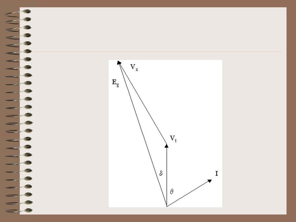
27 Resistive Load I R (Unity pf) R G X G V R V X = 0 E V T R Load V x E g V t I
28 Lagging Load I L (Lagging pf) R G X G V R V X E V T L Load E g -V x V t I
29 Capacitive Load I C (Leading pf) R G X G V R V X E V T C Load V t -V x E g I
30 V-curves Load MW (V Curve) 0.85 pf Lagging Load Load MVA 0.95 pf Leading Load (Under Excited) (AVR Bucking) Unity pf Load (Over Excited) (AVR Boosting) Decrease Increase Excitation Current
31 Governor Control I L Turbine V T Steam No Load Setpoint Gov. Valve Speed Governor Shaft Speed Variable Load Droop Setting
32 Speed Droop Electrical word for proportional control Speed Drop NL to FL Droop = 100% Rated Speed Isochronous - proportional + integral
33 Isochronous Freq. % Speed Change % % % Isochronous Governor % 60Hz 0 Constant Frequency % -2% -3% 25% 50% 75% 100% % Rated Load or MW %
34 4% Droop Freq. % Speed Change % +3% E D Governor Speed Droop Hz % +1% 0-1% C B A Loading Un-Loading 25% 50% 75% 100% % Rated Load or MW % % %
35 Effect of Adding Load
36 Generator Synchronized
37 Increasing Load 0.3 Hz{ 0.3 Hz{ MW Frequency (Hz) MW Load Generator G1 (MW) Load Generator G2 (MW)
38 Freq Unequal Speed Droops 61.8 B Hz A Load MW G1 G2
39 Finite Bus }0.6 Hz Hz{ 59.4 Frequency (Hz) Load Generator G1 (MW) Load Generator G2 (MW)
40 Frequency Restoration 0.6 Hz{ }0.6 Hz 59.4 Frequency (Hz) Load Generator G1 (MW) Load Generator G2 (MW)
41 Adjusting Steam Flow Steam Flow Armature Current Active Power Re active Po we r 1.0 Power Factor (Lagging).6 Time
42 Adjusting Excitation Field Current Armature Current Active Power Re active Po we r 1.0 Power Factor (Lagging).6 Time
43 Stability P V T X Transmisson Line V s Large System P = V T V s sin X
44 Power Transfer Curve Power Power Delivered to Load α V 2 V Before Fault P Steam t 0 Area B After Fault t 2 Area A During Fault t Load Angle δ t 3
45 Out of Step Angular + Velocity Pole slipping commences here (90 ) Rapid acceleration during pole slip ( ) Synchronism Speed Normal Operation (360-0 position) Generator tries to regain synchronism (a) Time MW Output Normal MW Output Surges in output power Time (b)
46 Generator Heating Q MVAR Reactive Power Lag Motoring U 2 = P 2 + Q 2 (Circle) U MVA Total Power Generating P MW Active Power Lead
47 Limits Q MVAR Reactive Power Lag A U 2 = P 2 + Q 2 (Circle) B 0.85 pf Lag U MVA Total Power < Motoring Generating > P MW Active Power Lead D C 0.95 pf Lead A-B Field Heating B-C Stator Heating C-D Stator Core End Heating
48 Stability Limits Q MVAR Reactive Power U 2 = P 2 + Q 2 (Circle) Lag A B 0.85 pf Lag U MVA Total Power < Motoring Generating > P MW Active Power Lead A-B Field Heating B-C Stator Heating C-D Stator Core End Heating Limit with No AVR Limit with Fast AVR
49 H 2 Pressure
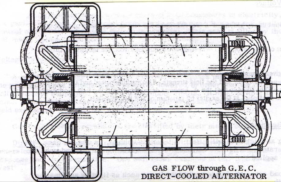
50 Cooling
51 For You To Do
ECE 325 Electric Energy System Components 7- Synchronous Machines. Instructor: Kai Sun Fall 2015
 ECE 325 Electric Energy System Components 7- Synchronous Machines Instructor: Kai Sun Fall 2015 1 Content (Materials are from Chapters 16-17) Synchronous Generators Synchronous Motors 2 Synchronous Generators
Introduction to Synchronous. Machines. Kevin Gaughan
 Introduction to Synchronous Machines Kevin Gaughan The Synchronous Machine An AC machine (generator or motor) with a stator winding (usually 3 phase) generating a rotating magnetic field and a rotor carrying
LESSON 20 ALTERNATOR OPERATION OF SYNCHRONOUS MACHINES
 ET 332b Ac Motors, Generators and Power Systems LESSON 20 ALTERNATOR OPERATION OF SYNCHRONOUS MACHINES 1 LEARNING OBJECTIVES After this presentation you will be able to: Interpret alternator phasor diagrams
Lesson 17: Synchronous Machines
 Lesson 17: Synchronous Machines ET 332b Ac Motors, Generators and Power Systems Lesson 17_et332b.pptx 1 Learning Objectives After this presentation you will be able to: Explain how synchronous machines
Synchronous Machines
 Synchronous Machines Synchronous generators or alternators are used to convert mechanical power derived from steam, gas, or hydraulic-turbine to ac electric power Synchronous generators are the primary
The Operation of a Generator on Infinite Busbars
 The Operation of a Generator on Infinite Busbars In order to simplify the ideas as much as possible the resistance of the generator will be neglected; in practice this assumption is usually reasonable.
QUESTION BANK ENGINEERS ACADEMY. Power Systems Power System Stability 1
 ower ystems ower ystem tability QUETION BANK. A cylindrical rotor generator delivers 0.5 pu power in the steady-state to an infinite bus through a transmission line of reactance 0.5 pu. The generator no-load
Power System Stability GENERATOR CONTROL AND PROTECTION
 Power System Stability Outline Basis for Steady-State Stability Transient Stability Effect of Excitation System on Stability Small Signal Stability Power System Stabilizers Speed Based Integral of Accelerating
Dynamic simulation of a five-bus system
 ELEC0047 - Power system dynamics, control and stability Dynamic simulation of a five-bus system Thierry Van Cutsem t.vancutsem@ulg.ac.be www.montefiore.ulg.ac.be/~vct November 2017 1 / 16 System modelling
Chapter 4. Synchronous Generators. Basic Topology
 Basic Topology Chapter 4 ynchronous Generators In stator, a three-phase winding similar to the one described in chapter 4. ince the main voltage is induced in this winding, it is also called armature winding.
EE 451 Power System Stability
 EE 451 Power System Stability Power system operates in synchronous mode Power system is subjected to a wide range of disturbances (small and large) - Loads and generation changes - Network changes - Faults
ECE 585 Power System Stability
 Homework 1, Due on January 29 ECE 585 Power System Stability Consider the power system below. The network frequency is 60 Hz. At the pre-fault steady state (a) the power generated by the machine is 400
Chapter 3 AUTOMATIC VOLTAGE CONTROL
 Chapter 3 AUTOMATIC VOLTAGE CONTROL . INTRODUCTION TO EXCITATION SYSTEM The basic function of an excitation system is to provide direct current to the field winding of the synchronous generator. The excitation
EE 742 Chapter 3: Power System in the Steady State. Y. Baghzouz
 EE 742 Chapter 3: Power System in the Steady State Y. Baghzouz Transmission Line Model Distributed Parameter Model: Terminal Voltage/Current Relations: Characteristic impedance: Propagation constant: π
University of Jordan Faculty of Engineering & Technology Electric Power Engineering Department
 University of Jordan Faculty of Engineering & Technology Electric Power Engineering Department EE471: Electrical Machines-II Tutorial # 2: 3-ph Induction Motor/Generator Question #1 A 100 hp, 60-Hz, three-phase
Torques 1.0 Two torques We have written the swing equation where speed is in rad/sec as:
 Torques 1.0 Two torques We have written the swing equation where speed is in rad/sec as: 2H Re ( t) T au T mu T eu (1) and when speed is in per-unit as 2H u ( t) Tau Tmu Teu (2) We note that in both cases
Massachusetts Institute of Technology Department of Electrical Engineering and Computer Science Electric Machines
 Massachusetts Institute of Technology Department of Electrical Engineering and Computer Science 6.685 Electric Machines Problem Set 10 Issued November 11, 2013 Due November 20, 2013 Problem 1: Permanent
You know for EE 303 that electrical speed for a generator equals the mechanical speed times the number of poles, per eq. (1).
.") Stability 1 1. Introduction We now begin Chapter 14.1 in your text. Our previous work in this course has focused on analysis of currents during faulted conditions in order to design protective systems
Stability 1 1. Introduction We now begin Chapter 14.1 in your text. Our previous work in this course has focused on analysis of currents during faulted conditions in order to design protective systems
Electrical Machines and Energy Systems: Operating Principles (Part 2) SYED A Rizvi
 SYED A Rizvi") Electrical Machines and Energy Systems: Operating Principles (Part 2) SYED A Rizvi AC Machines Operating Principles: Synchronous Motor In synchronous motors, the stator of the motor has a rotating magnetic
Electrical Machines and Energy Systems: Operating Principles (Part 2) SYED A Rizvi AC Machines Operating Principles: Synchronous Motor In synchronous motors, the stator of the motor has a rotating magnetic
An Introduction to Electrical Machines. P. Di Barba, University of Pavia, Italy
 An Introduction to Electrical Machines P. Di Barba, University of Pavia, Italy Academic year 0-0 Contents Transformer. An overview of the device. Principle of operation of a single-phase transformer 3.
KINGS COLLEGE OF ENGINEERING Punalkulam
 KINGS COLLEGE OF ENGINEERING Punalkulam 613 303 DEPARTMENT OF ELECTRICAL AND ELECTRONICS ENGINEERING POWER SYSTEM ANALYSIS QUESTION BANK UNIT I THE POWER SYSTEM AN OVERVIEW AND MODELLING PART A (TWO MARK
The synchronous machine (SM) in the power system (2) (Where does the electricity come from)?
 in the power system (2) (Where does the electricity come from)?") 1 The synchronous machine (SM) in the power system (2) (Where does the electricity come from)? 2 Lecture overview Synchronous machines with more than 2 magnetic poles The relation between the number of
1 The synchronous machine (SM) in the power system (2) (Where does the electricity come from)? 2 Lecture overview Synchronous machines with more than 2 magnetic poles The relation between the number of
JRE SCHOOL OF Engineering
 JRE SCHOOL OF Engineering Class Test-1 Examinations September 2014 Subject Name Electromechanical Energy Conversion-II Subject Code EEE -501 Roll No. of Student Max Marks 30 Marks Max Duration 1 hour Date
GENERATORS: PART 5. The student must be. 2. Explain how the current in a generator increases as it is loaded.
 Electrical Equipment - Course 23D.2 GENERATORS: PART 5 NFNTE BUS OPERATON 1. OBJECTVE The student must be able to: 1. Define an "infinite bus". 2. Explain how the current in a generator increases as it
INSTITUTE OF AERONAUTICAL ENGINEERING (Autonomous)
") INSTITUTE OF AERONAUTICAL ENGINEERING (Autonomous) Dundigal, Hyderabad - 500 043 ELECTRICAL AND ELECTRONICS ENGINEERING QUESTION BANK Course Name : Computer Methods in Power Systems Course Code : A60222
INSTITUTE OF AERONAUTICAL ENGINEERING (Autonomous) Dundigal, Hyderabad - 500 043 ELECTRICAL AND ELECTRONICS ENGINEERING QUESTION BANK Course Name : Computer Methods in Power Systems Course Code : A60222
EEE3405 ELECTRICAL ENGINEERING PRINCIPLES 2 - TEST
 ATTEMPT ALL QUESTIONS (EACH QUESTION 20 Marks, FULL MAKS = 60) Given v 1 = 100 sin(100πt+π/6) (i) Find the MS, period and the frequency of v 1 (ii) If v 2 =75sin(100πt-π/10) find V 1, V 2, 2V 1 -V 2 (phasor)
Modeling of Hydraulic Turbine and Governor for Dynamic Studies of HPP
 Modeling of Hydraulic Turbine and Governor for Dynamic Studies of HPP Nanaware R. A. Department of Electronics, Shivaji University, Kolhapur Sawant S. R. Department of Technology, Shivaji University, Kolhapur
MODULE TITLE : ELECTRICAL SUPPLY AND DISTRIBUTION SYSTEMS
 MODULE TITLE : ELECTRICAL SUPPLY AND DISTRIBUTION SYSTEMS TOPIC TITLE : THE OPERATION OF THREE-PHASE TRANSFORMERS IN PARALLEL AND GENERATORS ON INFINITE BUSBARS LESSON 2 : OPERATING CHARACTERISTICS OF
B.E. / B.Tech. Degree Examination, April / May 2010 Sixth Semester. Electrical and Electronics Engineering. EE 1352 Power System Analysis
 B.E. / B.Tech. Degree Examination, April / May 2010 Sixth Semester Electrical and Electronics Engineering EE 1352 Power System Analysis (Regulation 2008) Time: Three hours Answer all questions Part A (10
SCHOOL OF ELECTRICAL, MECHANICAL AND MECHATRONIC SYSTEMS. Transient Stability LECTURE NOTES SPRING SEMESTER, 2008
 SCHOOL OF ELECTRICAL, MECHANICAL AND MECHATRONIC SYSTEMS LECTURE NOTES Transient Stability SPRING SEMESTER, 008 October 7, 008 Transient Stability Transient stability refers to the ability of a synchronous
3 d Calculate the product of the motor constant and the pole flux KΦ in this operating point. 2 e Calculate the torque.
 Exam Electrical Machines and Drives (ET4117) 11 November 011 from 14.00 to 17.00. This exam consists of 5 problems on 4 pages. Page 5 can be used to answer problem 4 question b. The number before a question
EE2351 POWER SYSTEM OPERATION AND CONTROL UNIT I THE POWER SYSTEM AN OVERVIEW AND MODELLING PART A
 EE2351 POWER SYSTEM OPERATION AND CONTROL UNIT I THE POWER SYSTEM AN OVERVIEW AND MODELLING PART A 1. What are the advantages of an inter connected system? The advantages of an inter-connected system are
ECEN 460 Exam 1 Fall 2018
 ECEN 460 Exam 1 Fall 2018 Name: KEY UIN: Section: Score: Part 1 / 40 Part 2 / 0 Part / 0 Total / 100 This exam is 75 minutes, closed-book, closed-notes. A standard calculator and one 8.5 x11 note sheet
Electrical Machines and Energy Systems: Operating Principles (Part 1) SYED A Rizvi
 SYED A Rizvi") Electrical Machines and Energy Systems: Operating Principles (Part 1) SYED A Rizvi AC Machines Operating Principles: Rotating Magnetic Field The key to the functioning of AC machines is the rotating magnetic
Electrical Machines and Energy Systems: Operating Principles (Part 1) SYED A Rizvi AC Machines Operating Principles: Rotating Magnetic Field The key to the functioning of AC machines is the rotating magnetic
Chapter 9: Transient Stability
 Chapter 9: Transient Stability 9.1 Introduction The first electric power system was a dc system built by Edison in 1882. The subsequent power systems that were constructed in the late 19 th century were
THE UNIVERSITY OF NEW SOUTH WALES. School of Electrical Engineering & Telecommunications FINALEXAMINATION. Session
 Name: Student ID: Signature: THE UNIVERSITY OF NEW SOUTH WALES School of Electrical Engineering & Telecommunications FINALEXAMINATION Session 00 ELEC46 Power System Analysis TIME ALLOWED: 3 hours TOTAL
Control of Wind Turbine Generators. James Cale Guest Lecturer EE 566, Fall Semester 2014 Colorado State University
 Control of Wind Turbine Generators James Cale Guest Lecturer EE 566, Fall Semester 2014 Colorado State University Review from Day 1 Review Last time, we started with basic concepts from physics such as
Chapter 6. Induction Motors. Copyright The McGraw-Hill Companies, Inc. Permission required for reproduction or display.
 Chapter 6 Induction Motors 1 The Development of Induced Torque in an Induction Motor Figure 6-6 The development of induced torque in an induction motor. (a) The rotating stator field B S induces a voltage
Prince Sattam bin Abdulaziz University College of Engineering. Electrical Engineering Department EE 3360 Electrical Machines (II)
") Chapter # 4 Three-Phase Induction Machines 1- Introduction (General Principles) Generally, conversion of electrical power into mechanical power takes place in the rotating part of an electric motor. In
Chapter # 4 Three-Phase Induction Machines 1- Introduction (General Principles) Generally, conversion of electrical power into mechanical power takes place in the rotating part of an electric motor. In
UNIT I INTRODUCTION Part A- Two marks questions
 ROEVER COLLEGE OF ENGINEERING & TECHNOLOGY ELAMBALUR, PERAMBALUR-621220 DEPARTMENT OF ELECTRICAL AND ELECTRONICS ENGINEERING DESIGN OF ELECTRICAL MACHINES UNIT I INTRODUCTION 1. Define specific magnetic
Power System Stability and Control. Dr. B. Kalyan Kumar, Department of Electrical Engineering, Indian Institute of Technology Madras, Chennai, India
 Power System Stability and Control Dr. B. Kalyan Kumar, Department of Electrical Engineering, Indian Institute of Technology Madras, Chennai, India Contents Chapter 1 Introduction to Power System Stability
Generators for wind power conversion
 Generators for wind power conversion B. G. Fernandes Department of Electrical Engineering Indian Institute of Technology, Bombay Email : bgf@ee.iitb.ac.in Outline of The Talk Introduction Constant speed
ELG4125: Power Transmission Lines Steady State Operation
 ELG4125: Power Transmission Lines Steady State Operation Two-Port Networks and ABCD Models A transmission line can be represented by a two-port network, that is a network that can be isolated from the
Micro-grid to System Synchronization Based on Pre-Insertion Impedance Method (Version 1.0) By Peter Zhou University of Alberta Jan 30 th, 2015
 By Peter Zhou University of Alberta Jan 30 th, 2015") Micro-grid to System Synchronization Based on Pre-Insertion Impedance Method (Version 1.0) By Peter Zhou University of Alberta Jan 30 th, 2015 Outline 1. What is Synchronization? 2. Synchronization Concerns?
Micro-grid to System Synchronization Based on Pre-Insertion Impedance Method (Version 1.0) By Peter Zhou University of Alberta Jan 30 th, 2015 Outline 1. What is Synchronization? 2. Synchronization Concerns?
ECEN 667 Power System Stability Lecture 18: Voltage Stability, Load Models
 ECEN 667 Power System Stability Lecture 18: Voltage Stability, Load Models Prof. Tom Overbye Dept. of Electrical and Computer Engineering Texas A&M University, overbye@tamu.edu 1 Announcements Read Chapter
EE Branch GATE Paper 2010
 Q.1 Q.25 carry one mark each 1. The value of the quantity P, where, is equal to 0 1 e 1/e 2. Divergence of the three-dimensional radial vector field is 3 1/r 3. The period of the signal x(t) = 8 is 0.4
GATE 2010 Electrical Engineering
 GATE 2010 Electrical Engineering Q.1 Q.25 carry one mark each 1. The value of the quantity P, where P = xe dx, is equal to (A) 0 (B) 1 (C) e (D) 1/e 2. Divergence of the three-dimensional radial vector
+ ( )= with initial condition
= with initial condition") Department of Electrical Engineering PhD. Admission Test Full Marks: 90 Time 90 minutes Date: 02.2.204 NAME: Appl. No: Write your answer on the question paper ONLY. All questions carry equal marks. PART
Department of Electrical Engineering PhD. Admission Test Full Marks: 90 Time 90 minutes Date: 02.2.204 NAME: Appl. No: Write your answer on the question paper ONLY. All questions carry equal marks. PART
POWER SYSTEM STABILITY
 LESSON SUMMARY-1:- POWER SYSTEM STABILITY 1. Introduction 2. Classification of Power System Stability 3. Dynamic Equation of Synchronous Machine Power system stability involves the study of the dynamics
Transient Stability Analysis with PowerWorld Simulator
 Transient Stability Analysis with PowerWorld Simulator T1: Transient Stability Overview, Models and Relationships 2001 South First Street Champaign, Illinois 61820 +1 (217) 384.6330 support@powerworld.com
A Power System Dynamic Simulation Program Using MATLAB/ Simulink
 A Power System Dynamic Simulation Program Using MATLAB/ Simulink Linash P. Kunjumuhammed Post doctoral fellow, Department of Electrical and Electronic Engineering, Imperial College London, United Kingdom
SSC-JE EE POWER SYSTEMS: GENERATION, TRANSMISSION & DISTRIBUTION SSC-JE STAFF SELECTION COMMISSION ELECTRICAL ENGINEERING STUDY MATERIAL
 1 SSC-JE STAFF SELECTION COMMISSION ELECTRICAL ENGINEERING STUDY MATERIAL Power Systems: Generation, Transmission and Distribution Power Systems: Generation, Transmission and Distribution Power Systems:
Electric Machines I Three Phase Induction Motor. Dr. Firas Obeidat
 Electric Machines I Three Phase Induction Motor Dr. Firas Obeidat 1 Table of contents 1 General Principles 2 Construction 3 Production of Rotating Field 4 Why Does the Rotor Rotate 5 The Slip and Rotor
7. Transient stability
 1 7. Transient stability In AC power system, each generator is to keep phase relationship according to the relevant power flow, i.e. for a certain reactance X, the both terminal voltages V1and V2, and
Synchronous Machines
 Synchronous Machines Synchronous Machines n 1 Φ f n 1 Φ f I f I f I f damper (run-up) winding Stator: similar to induction (asynchronous) machine ( 3 phase windings that forms a rotational circular magnetic
Modelling of Primary Frequency Control and Effect Analyses of Governing System Parameters on the Grid Frequency. Zhixin Sun
 Modelling of Primary Frequency Control and Effect Analyses of Governing System Parameters on the Grid Frequency Zhixin Sun Outline Introduction Mathematical Model of Primary Frequency Control Dynamic Test
Synchronous Machines
 Synchronous machine 1. Construction Generator Exciter View of a twopole round rotor generator and exciter. A Stator with laminated iron core C Slots with phase winding B A B Rotor with dc winding B N S
ECE 421/521 Electric Energy Systems Power Systems Analysis I 3 Generators, Transformers and the Per-Unit System. Instructor: Kai Sun Fall 2013
 ECE 41/51 Electric Energy Systems Power Systems Analysis I 3 Generators, Transformers and the Per-Unit System Instructor: Kai Sun Fall 013 1 Outline Synchronous Generators Power Transformers The Per-Unit
Generation, transmission and distribution, as well as power supplied to industrial and commercial customers uses a 3 phase system.
 Three-phase Circuits Generation, transmission and distribution, as well as power supplied to industrial and commercial customers uses a 3 phase system. Where 3 voltages are supplied of equal magnitude,
A. P. Sakis Meliopoulos and George J. Cokkinides Power System Relaying, Theory and Applications. Chapter 8 2 Generator Protection 2
 DRAFT and INCOMPLETE Table of Contents from A. P. Sakis Meliopoulos and George J. Cokkinides Power System Relaying, Theory and Applications Chapter 8 Generator Protection 8. Introduction 8. Generator Protection
ROEVER COLLEGE OF ENGINEERING & TECHNOLOGY ELAMBALUR, PERAMBALUR DEPARTMENT OF ELECTRICAL AND ELECTRONICS ENGINEERING ELECTRICAL MACHINES I
 ROEVER COLLEGE OF ENGINEERING & TECHNOLOGY ELAMBALUR, PERAMBALUR-621220 DEPARTMENT OF ELECTRICAL AND ELECTRONICS ENGINEERING ELECTRICAL MACHINES I Unit I Introduction 1. What are the three basic types
Power System Analysis Prof. A. K. Sinha Department of Electrical Engineering Indian Institute of Technology, Kharagpur
 Power System Analysis Prof. A. K. Sinha Department of Electrical Engineering Indian Institute of Technology, Kharagpur Lecture - 9 Transmission Line Steady State Operation Welcome to lesson 9, in Power
Brief Steady of Power Factor Improvement
 International Journal of Electrical Engineering. ISSN 0974-2158 Volume 6, Number 5 (2013), pp. 531-539 International Research PublicationHouse http://www.irphouse.com Brief Steady of Power Factor Improvement
BASIC PRINCIPLES. Power In Single-Phase AC Circuit
 BASIC PRINCIPLES Power In Single-Phase AC Circuit Let instantaneous voltage be v(t)=v m cos(ωt+θ v ) Let instantaneous current be i(t)=i m cos(ωt+θ i ) The instantaneous p(t) delivered to the load is p(t)=v(t)i(t)=v
GATE 2008 Electrical Engineering
 GATE 2008 Electrical Engineering Q.1 Q. 20 carry one mark each. 1. The number of chords in the graph of the given circuit will be + _ (A) 3 (B) 4 (C) 5 (D) 6 2. The Thevenin'a equivalent of a circuit operating
Transient Stability Analysis of Single Machine Infinite Bus System by Numerical Methods
 International Journal of Electrical and Electronics Research ISSN 348-6988 (online) Vol., Issue 3, pp: (58-66), Month: July - September 04, Available at: www.researchpublish.com Transient Stability Analysis
Lecture (20) DC Machine Examples Start of Synchronous Machines
 DC Machine Examples Start of Synchronous Machines") Lecture (20) DC Machine Examples Start of Synchronous Machines Energy Systems Research Laboratory, FIU All rights reserved. 20-1 Energy Systems Research Laboratory, FIU All rights reserved. 20-2 Ra R f
Lecture (20) DC Machine Examples Start of Synchronous Machines Energy Systems Research Laboratory, FIU All rights reserved. 20-1 Energy Systems Research Laboratory, FIU All rights reserved. 20-2 Ra R f
CHAPTER 5 SIMULATION AND TEST SETUP FOR FAULT ANALYSIS
 47 CHAPTER 5 SIMULATION AND TEST SETUP FOR FAULT ANALYSIS 5.1 INTRODUCTION This chapter describes the simulation model and experimental set up used for the fault analysis. For the simulation set up, the
Comparative Study of Synchronous Machine, Model 1.0 and Model 1.1 in Transient Stability Studies with and without PSS
 Comparative Study of Synchronous Machine, Model 1.0 and Model 1.1 in Transient Stability Studies with and without PSS Abhijit N Morab, Abhishek P Jinde, Jayakrishna Narra, Omkar Kokane Guide: Kiran R Patil
POWER SYSTEM STABILITY AND CONTROL
 POWER SYSTEM STABILITY AND CONTROL P. KUNDUR Vice-President, Power Engineering Powertech Labs Inc., Surrey, British Columbia Formerly Manager Analytical Methods and Specialized Studies Department Power
Chapter 8: Unsymmetrical Faults
 Chapter 8: Unsymmetrical Faults Introduction The sequence circuits and the sequence networks developed in the previous chapter will now be used for finding out fault current during unsymmetrical faults.
RESULTS OF ON-GRID OPERATION OF SUPERCONDUCTOR DYNAMIC SYNCHRONOUS CONDENSER
 1 RESULTS OF ON-GRID OPERATION OF SUPERCONDUCTOR DYNAMIC SYNCHRONOUS CONDENSER Dr. Swarn S. Kalsi, David Madura, and Michael Ross American Superconductor Corporation (USA) Abstract: A high-temperature
د شوقي حامد عرفه ابراهيم
 2015 /1/19 اإلجابة النموذجية لمادة نظم التشغيل الكهربية ك 563 د شوقي حامد عرفه ابراهيم يوم االثنين الموافق Benha University Benha Faculty of Engineering Subject: Electrical drives (E563) Time: 3hours Fifth
Doubly salient reluctance machine or, as it is also called, switched reluctance machine. [Pyrhönen et al 2008]
![Doubly salient reluctance machine or, as it is also called, switched reluctance machine. [Pyrhönen et al 2008]](/thumbs/86/93665357.jpg "Doubly salient reluctance machine or, as it is also called, switched reluctance machine. [Pyrhönen et al 2008]") Doubly salient reluctance machine or, as it is also called, switched reluctance machine [Pyrhönen et al 2008] Pros and contras of a switched reluctance machine Advantages Simple robust rotor with a small
Doubly salient reluctance machine or, as it is also called, switched reluctance machine [Pyrhönen et al 2008] Pros and contras of a switched reluctance machine Advantages Simple robust rotor with a small
CHAPTER 3 MATHEMATICAL MODELING OF HYDEL AND STEAM POWER SYSTEMS CONSIDERING GT DYNAMICS
 28 CHAPTER 3 MATHEMATICAL MODELING OF HYDEL AND STEAM POWER SYSTEMS CONSIDERING GT DYNAMICS 3.1 INTRODUCTION This chapter focuses on the mathematical state space modeling of all configurations involved
Transient Stability Assessment of Synchronous Generator in Power System with High-Penetration Photovoltaics (Part 2)
") Journal of Mechanics Engineering and Automation 5 (2015) 401-406 doi: 10.17265/2159-5275/2015.07.003 D DAVID PUBLISHING Transient Stability Assessment of Synchronous Generator in Power System with High-Penetration
Journal of Mechanics Engineering and Automation 5 (2015) 401-406 doi: 10.17265/2159-5275/2015.07.003 D DAVID PUBLISHING Transient Stability Assessment of Synchronous Generator in Power System with High-Penetration
EE2351 POWER SYSTEM ANALYSIS UNIT I: INTRODUCTION
 EE2351 POWER SYSTEM ANALYSIS UNIT I: INTRODUCTION PART: A 1. Define per unit value of an electrical quantity. Write equation for base impedance with respect to 3-phase system. 2. What is bus admittance
Electromagnetic Energy Conversion Exam 98-Elec-A6 Spring 2002
 Front Page Electromagnetic Energy Conversion Exam 98-Elec-A6 Spring 2002 Notes: Attempt question 1 and FOUR (4) other questions (FVE (5) questions in all). Unless you indicate otherwise, the first five
Dynamics of the synchronous machine
 ELEC0047 - Power system dynamics, control and stability Dynamics of the synchronous machine Thierry Van Cutsem t.vancutsem@ulg.ac.be www.montefiore.ulg.ac.be/~vct October 2018 1 / 38 Time constants and
Equal Pitch and Unequal Pitch:
 Equal Pitch and Unequal Pitch: Equal-Pitch Multiple-Stack Stepper: For each rotor stack, there is a toothed stator segment around it, whose pitch angle is identical to that of the rotor (θs = θr). A stator
Outcome of this lecture
 Outcome of this lecture At the en of this lecture you will be able to: List the ifferent parts of a synchronous machine Explain the operation principles of the machine Use the equivalent circuit moel of
Eddy Current Heating in Large Salient Pole Generators
 Eddy Current Heating in Large Salient Pole Generators C.P.Riley and A.M. Michaelides Vector Fields Ltd., 24 Bankside, Kidlington, Oxford OX5 1JE, UK phone: (+44) 1865 370151, fax: (+44) 1865 370277 e-mail:
EE2351 POWER SYSTEM ANALYSIS
 EE351 POWER SYSTEM ANALYSIS A.Ahamed Riazudeen EEE DEPARTMENT 1 UNIT I INTRODUCTION Power system network 3 SINGLE LINE DIAGRAM It is a diagrammatic representation of a power system in which the components
Q. 1 Q. 25 carry one mark each.
 Q. 1 Q. 25 carry one mark each. Q.1 Given ff(zz) = gg(zz) + h(zz), where ff, gg, h are complex valued functions of a complex variable zz. Which one of the following statements is TUE? (A) If ff(zz) is
The Effects of Machine Components on Bifurcation and Chaos as Applied to Multimachine System
 1 The Effects of Machine Components on Bifurcation and Chaos as Applied to Multimachine System M. M. Alomari and B. S. Rodanski University of Technology, Sydney (UTS) P.O. Box 123, Broadway NSW 2007, Australia
Electromagnetic Torque From Event Report Data A Measure of Machine Performance
 Electromagnetic Torque From Event Report Data A Measure of Machine Performance Derrick Haas and Dale Finney Schweitzer Engineering Laboratories, Inc. 7 SEL Overview Electromagnetic torque calculation Modeling
Performance Analysis of Self-Excited Induction Generator Driven At Variable Wind Speeds
 International Journal of Engineering and Advanced Technology (IJEAT) ISSN: 2249 8958, Volume-1, Issue-2, December 2011 Performance Analysis of Self-Excited Induction Generator Driven At Variable Wind Speeds
ECE 420. Review of Three Phase Circuits. Copyright by Chanan Singh, Panida Jirutitijaroen, and Hangtian Lei, For educational use only-not for sale.
 ECE 40 Review of Three Phase Circuits Outline Phasor Complex power Power factor Balanced 3Ф circuit Read Appendix A Phasors and in steady state are sinusoidal functions with constant frequency 5 0 15 10
CENTRAL TERMOELÉCTRICA ANDINA UNIDAD Nº 1
 PROYECTO PROJECT CENTRAL TERMOELÉCTRICA ANDINA UNIDAD Nº 1 TÍTULO TITLE Technical Data and curves of the Generator Nº DE DOCUMENTO PROYECTO PROJECT DOCUMENT Nº CTA-12-MA EHP-SK-0086_Rev00 REV 00 FECHA
Review of Basic Electrical and Magnetic Circuit Concepts EE
 Review of Basic Electrical and Magnetic Circuit Concepts EE 442-642 Sinusoidal Linear Circuits: Instantaneous voltage, current and power, rms values Average (real) power, reactive power, apparent power,
Performance Evaluation of DFIG to Changes in Network Frequency
 019 CIENCELINE Journal of World s Electrical Engineering and Technology J. World. Elect. Eng. Tech. 8(1): 01-06, 019 JWEET Performance Evaluation of DFIG to Changes in Network Frequency Ramin Tayebi-Derazkolaie
DYNAMIC RESPONSE OF A GROUP OF SYNCHRONOUS GENERATORS FOLLOWING DISTURBANCES IN DISTRIBUTION GRID
 Engineering Review Vol. 36 Issue 2 8-86 206. 8 DYNAMIC RESPONSE OF A GROUP OF SYNCHRONOUS GENERATORS FOLLOWING DISTURBANCES IN DISTRIBUTION GRID Samir Avdaković * Alija Jusić 2 BiH Electrical Utility Company
Module 3 : Sequence Components and Fault Analysis
 Module 3 : Sequence Components and Fault Analysis Lecture 12 : Sequence Modeling of Power Apparatus Objectives In this lecture we will discuss Per unit calculation and its advantages. Modeling aspects
6.061 / Introduction to Electric Power Systems
 MIT OpenCourseWare http://ocw.mit.edu 6.061 / 6.690 Introduction to Electric Power Systems Spring 2007 For information about citing these materials or our Terms of Use, visit: http://ocw.mit.edu/terms.
EE 410/510: Electromechanical Systems Chapter 4
 EE 410/510: Electromechanical Systems Chapter 4 Chapter 4. Direct Current Electric Machines and Motion Devices Permanent Magnet DC Electric Machines Radial Topology Simulation and Experimental Studies
1 Unified Power Flow Controller (UPFC)
") Power flow control with UPFC Rusejla Sadikovic Internal report 1 Unified Power Flow Controller (UPFC) The UPFC can provide simultaneous control of all basic power system parameters ( transmission voltage,
Power flow control with UPFC Rusejla Sadikovic Internal report 1 Unified Power Flow Controller (UPFC) The UPFC can provide simultaneous control of all basic power system parameters ( transmission voltage,
ANALYSIS OF SUBSYNCHRONOUS RESONANCE EFFECT IN SERIES COMPENSATED LINE WITH BOOSTER TRANSFORMER
 ANALYSIS OF SUBSYNCHRONOUS RESONANCE EFFECT IN SERIES COMPENSATED LINE WITH BOOSTER TRANSFORMER G.V.RAJASEKHAR, 2 GVSSNS SARMA,2 Department of Electrical Engineering, Aurora Engineering College, Hyderabad,
Equivalent Circuits with Multiple Damper Windings (e.g. Round rotor Machines)
") Equivalent Circuits with Multiple Damper Windings (e.g. Round rotor Machines) d axis: L fd L F - M R fd F L 1d L D - M R 1d D R fd R F e fd e F R 1d R D Subscript Notations: ( ) fd ~ field winding quantities
Equivalent Circuits with Multiple Damper Windings (e.g. Round rotor Machines) d axis: L fd L F - M R fd F L 1d L D - M R 1d D R fd R F e fd e F R 1d R D Subscript Notations: ( ) fd ~ field winding quantities
MAHARASHTRA STATE BOARD OF TECHNICAL EDUCATION
 Important Instructions to examiners: 1) The answers should be examined by key words and not as word-to-word as given in the model answer scheme. 2) The model answer and the answer written by candidate
Analyzing the Effect of Ambient Temperature and Loads Power Factor on Electric Generator Power Rating
 Analyzing the Effect of Ambient Temperature and Loads Power Factor on Electric Generator Power Rating Ahmed Elsebaay, Maged A. Abu Adma, Mahmoud Ramadan Abstract This study presents a technique clarifying