Synchronous Machines - Structure
|
|
|
- Mitchell Watson
- 6 years ago
- Views:
Transcription
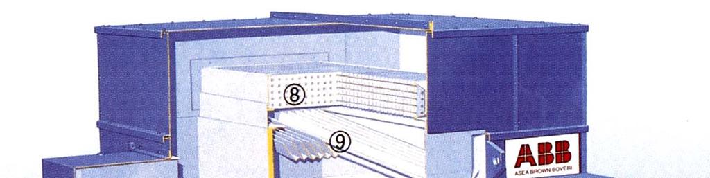
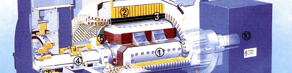
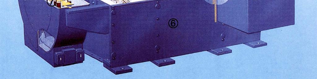
1 Synchronou Machine - Structure
2

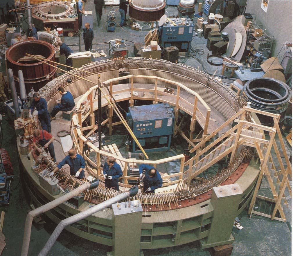
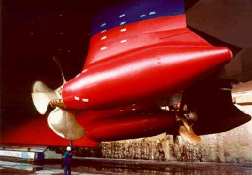
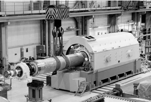
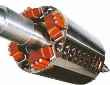
3 Synchronou Machine - Structure rotate at contant peed. primary energy converion device of the word electric power ytem. both generator and motor operation can draw either a lagging or a leading reactive current from the upply ytem. Non-alient pole generator high peed (2-4 pole) large power ( MVA) team and nuclear power plant Salient pole generator mall and mid-ize power ( MVA) mall motor for electrical clock and other dometic device mid ize generator for emergency power upply mid ize motor for pump and hip propulion large ize generator in hydro-electric power plant
4 Synchronou Generator No-load excitation voltage frequency depend on the peed f = np 120 n = 120 f p E f NK f = 4.44 Φf w Ef f nφ open circuit characteritic magnetization characteritic
5 Synchronou Generator - loaded the tator current will etablih a rotating field in the air-gap armature reaction flux Φ a reultant air-gap flux Φ = Φ + Φ r f a
6 Synchronou Machine The Infinite Bu
7 Synchronou Machine Paralleling with The Infinite Bu ame voltage frequency phae equence phae ynchronizing lamp 1. Same f and phae equence 2. Same V and phae equence 1. Same V and f


8 Synchronou Motor - Starting high inertia of the rotor prohibit direct connection into upply net variable-frequency upply tart a an induction motor
9 Synchronou Machine Per Phae Equivalent Circuit Model armature flux, armature reaction flux, armature leakage flux Φa = Φar + Φal Φ = Φ + Φ r Er = Ear + Ef E = j I ar f ( If ) ar ( Ia ) ar a E = I j + E f a ar r magnetizing reactance ar, (reactance of armature) ynchronou reactance = ar + al ynchronou impedance Z =R a + j
10 Synchronou Machine Equivalent Circuit Model Norton equivalent circuit I E f f ar = If 2 N = ni re f n = 3 N e
11 Equivalent Circuit Model Determination of the Synchronou Reactance open circuit tet ynchronou peed tator open-circuited meaure V t (I f ) open-circuit characteritic air-gap line hort circuit tet ynchronou peed tator hort-circuited meaure I a (I f ) hort-circuit characteritic traight line flux remain at low level I a lag the E f by almot 90 becaue R a
12 Equivalent Circuit Model Determination of the Synchronou Reactance unaturated value from the air-gap line E Z R j (unat) da da = = a + (unat) (unat) Iba Iba E
13 Equivalent Circuit Model Determination of the Synchronou Reactance Saturated E = V + I ( R + j ) V r t a a al t at infinite bu operation the aturation level i defined by terminal voltage operation point c if the field current i changed the excitation voltage will change along modified air-gap line OC Eca Z(at) = = Ra + j I ba (at) (at) E I ca ba
14 Synchronou Machine Phaor Diagram terminal voltage taken a the reference vector generator power angle poitive E = V + I R + I j = E δ f t a a a motor power angle negative V = E + I R + I j t f a a a f E = V 0 I R I j f t a a a = E δ f convention: generating current flow out of the machine
15 Synchronou Machine Power and Torque V t Vt 0 f = E = E δ f Z = Ra + j = Z θ S * t a = V I I * * * * Ef Vt Ef Vt a = = * * Z Z Z Ef δ = Z θ θ Ef Vt = θ δ θ Z Z Z V t 0 convention: lagging reactive power poitive
16 Synchronou Machine Power and Torque complex power Vt Ef Vt S = θ δ θ Z Z 2 real power Vt Ef Vt P = co( θ δ) coθ Z Z 2 reactive power Vt Ef Vt Q = in( θ δ) inθ Z Z 2
17 R a neglected real power Synchronou Machine Power and Torque 3 V E P φ δ inδ t f 3 = in = Pmax reactive power Q 3φ 3Vt Ef 3V = coδ t 2 torque T = P3 φ δ δ ω = 3 Vt Ef in ω = Tmax in N m yn yn
18 Synchronou Machine Complex Power Locu 3 V E P φ δ inδ t f 3 = in = Pmax Q 3φ 3Vt Ef 3V = coδ t 2
19 Synchronou Machine Capability Curve armature heating, length of OM field heating, length of YM teady-tate tability δ
20 Synchronou Machine Power Factor Control machine connected to an infinite bu P= 3VtIacoφ for contant power operation Ia co φ = cont. reactive current can be controlled by field current j I = V E a t f alo P = 3 VE t f in δ E f inδ = cont
21 Synchronou Machine Independent Generator purely inductive load (I c i hort-circuit current) V = E I I t f a a V = I I c a = ( I I ) c a purely reitive load E I = = R R = I R t a L f c 2 L L + 2 quarter ellipe 2 Vt 2 Ia c 2 2 Ic ( I ) + = 1 control curve contant terminal voltage
22 Salient Pole Synchronou Machine the field mmf and flux are along the d-axi tator current i in phae with the excitation voltage armature mmf and flux are along the q-axi tator current i lagging the excitation voltage by 90 degree armature mmf and flux act along the d-axi, directly oppoing the field the ame magnitude of the armature mmf produce more flux in d- direction than that in q-direction magnetizing reactance i not unique in a alient pole machine
23 Salient Pole Synchronou Machine the armature quantitie can be reolved into two component one acting along the d-axi (F d, I d ), and the other acting along the q-axi (F q, I q ), thee component produce fluxe along the repective axe (Φ ad, Φ aq ), d-axi armature reactance d q-axi armature reactance q leakage reactance al ynchronou reactance d = ad + al q = aq + al
24 Salient Pole Synchronou Machine Phaor Diagram the component current (I d, I q ), produce component voltage drop (ji d d, ji q q ) E = V + I R + I j + I j Ia = I + Iq f t a a d d q q generator phaor diagram (I a lagging) d ψ internal power factor angle φ terminal power factor angle δ torque angle R a neglected
25 Salient Pole Synchronou Machine Phaor Diagram motoring phaor diagram (I a lagging) ψ internal power factor angle φ terminal power factor angle δ torque angle V = E + I j + I j t f d d q q ψ = φ ± δ I I I d = ainψ = ain( φ ± δ ) tanδ = V I a ± q I t a q coφ inφ I = I coψ = I co( φ ± δ ) q a a E = V coδ ± I f t d d
26 Power Tranfer S * t a = V I = V δ ( I j I ) t q d * = V δ ( I + j I ) t q d I d = E f V t d coδ I q = V t inδ q
27 Power Tranfer 2 2 t t f t V V E V S= inδ δ + 90 δ coδ 90 δ = P+ jq q d d d 2 Vt Ef Vt ( d q) P= inδ + in 2δ = Pf + P 2 d q r Q d 2 2 Vt Ef 2 in δ co = coδ Vt + q d δ if d = q, then P = V E t d f inδ Q Vt Ef = coδ d V t d 2
28 Power Tranfer - Torque d 2 Vt Ef Vt ( d q) P= inδ + in 2δ = Pf + P 2 d q r


29 Determination of d and q lip tet rotor i driven at a mall lip field winding open-circuited tator i connected to a balanced three phae upply tator encounter varying reluctance path amplitude of the tator current varie d = i V t min 2 q = i V t max 2
30 Speed Control of Synchronou Motor open-loop frequency control
31 frequency control Speed Control of Synchronou Motor P = Tω = ω = m m 4π f p 3VE t f inδ = 2π fl field current kept contant Ef = K f 1 V T = K t inδ f voltage i changed with the frequency
32 Speed Control of Synchronou Motor elf-controlled ynchronou motor rotor poition information i ued to decreae the tator frequency open-loop / cloed-loop control
33 Application ac generator contant peed operation high efficiency motor-generator et, air compreor, centrifugal pump, blower, cruher, mill power factor control, ynchronou reactor, -condener
Outcome of this lecture
 Outcome of this lecture At the en of this lecture you will be able to: List the ifferent parts of a synchronous machine Explain the operation principles of the machine Use the equivalent circuit moel of
BASIC INDUCTION MOTOR CONCEPTS
 INDUCTION MOTOS An induction motor ha the ame phyical tator a a ynchronou machine, with a different rotor contruction. There are two different type of induction motor rotor which can be placed inide the
Chapter 4. Synchronous Generators. Basic Topology
 Basic Topology Chapter 4 ynchronous Generators In stator, a three-phase winding similar to the one described in chapter 4. ince the main voltage is induced in this winding, it is also called armature winding.
15 Problem 1. 3 a Draw the equivalent circuit diagram of the synchronous machine. 2 b What is the expected synchronous speed of the machine?
 Exam Electrical Machine and Drive (ET4117) 6 November 009 from 9.00 to 1.00. Thi exam conit of 4 problem on 4 page. Page 5 can be ued to anwer problem quetion b. The number before a quetion indicate how
ECE 325 Electric Energy System Components 6- Three-Phase Induction Motors. Instructor: Kai Sun Fall 2015
 ECE 35 Electric Energy Sytem Component 6- Three-Phae Induction Motor Intructor: Kai Sun Fall 015 1 Content (Material are from Chapter 13-15) Component and baic principle Selection and application Equivalent
Introduction to Synchronous. Machines. Kevin Gaughan
 Introduction to Synchronous Machines Kevin Gaughan The Synchronous Machine An AC machine (generator or motor) with a stator winding (usually 3 phase) generating a rotating magnetic field and a rotor carrying
60 p. 2. A 200hp 600V, 60 Hz 3-phase induction motor has start code F. What line current should be expected at starting? 4 marks.
 EE 004 Final Solution : Thi wa a hr exam. A 60 Hz 4 pole -phae induction motor rotate at 740rpm. a) What i the lip? mark b) What i the peed o rotation o the rotor magnetic ield (in rpm)? mark The motor
Section Induction motor drives
 Section 5.1 - nduction motor drive Electric Drive Sytem 5.1.1. ntroduction he AC induction motor i by far the mot widely ued motor in the indutry. raditionally, it ha been ued in contant and lowly variable-peed
Synchronous Machines
 Synchronous Machines Synchronous generators or alternators are used to convert mechanical power derived from steam, gas, or hydraulic-turbine to ac electric power Synchronous generators are the primary
Basic parts of an AC motor : rotor, stator, The stator and the rotor are electrical
 INDUCTION MOTO 1 CONSTUCTION Baic part of an AC motor : rotor, tator, encloure The tator and the rotor are electrical circuit that perform a electromagnet. CONSTUCTION (tator) The tator - tationary part
No-load And Blocked Rotor Test On An Induction Machine
 No-load And Blocked Rotor Tet On An Induction Machine Aim To etimate magnetization and leakage impedance parameter of induction machine uing no-load and blocked rotor tet Theory An induction machine in
Lecture Set 8 Induction Machines
 Lecture Set 8 Induction Machine S.D. Sudhoff Spring 2018 Reading Chapter 6, Electromechanical Motion Device, Section 6.1-6.9, 6.12 2 Sample Application Low Power: Shaded pole machine (mall fan) Permanent
Overview: Induction Motors. Review Questions. Why the Rotor Moves: Motor Speed
 Overview: nduction Motor Motor operation & Slip Speed-torque relationhip Equivalent circuit model Tranformer Motor efficiency Starting induction motor Smith College, EGR 35 ovember 5, 04 Review Quetion
Induction Motor Drive
 Induction Motor Drive 1. Brief review of IM theory.. IM drive characteritic with: Variable input voltage Variable rotor reitance Variable rotor power Variable voltage and variable frequency, VVVF drive
Lesson 17: Synchronous Machines
 Lesson 17: Synchronous Machines ET 332b Ac Motors, Generators and Power Systems Lesson 17_et332b.pptx 1 Learning Objectives After this presentation you will be able to: Explain how synchronous machines
EE 742 Chapter 3: Power System in the Steady State. Y. Baghzouz
 EE 742 Chapter 3: Power System in the Steady State Y. Baghzouz Transmission Line Model Distributed Parameter Model: Terminal Voltage/Current Relations: Characteristic impedance: Propagation constant: π
Equivalent Circuits with Multiple Damper Windings (e.g. Round rotor Machines)
") Equivalent Circuits with Multiple Damper Windings (e.g. Round rotor Machines) d axis: L fd L F - M R fd F L 1d L D - M R 1d D R fd R F e fd e F R 1d R D Subscript Notations: ( ) fd ~ field winding quantities
Equivalent Circuits with Multiple Damper Windings (e.g. Round rotor Machines) d axis: L fd L F - M R fd F L 1d L D - M R 1d D R fd R F e fd e F R 1d R D Subscript Notations: ( ) fd ~ field winding quantities
Massachusetts Institute of Technology Department of Electrical Engineering and Computer Science Electric Machines
 Massachusetts Institute of Technology Department of Electrical Engineering and Computer Science 6.685 Electric Machines Problem Set 10 Issued November 11, 2013 Due November 20, 2013 Problem 1: Permanent
ROEVER COLLEGE OF ENGINEERING & TECHNOLOGY ELAMBALUR, PERAMBALUR DEPARTMENT OF ELECTRICAL AND ELECTRONICS ENGINEERING ELECTRICAL MACHINES I
 ROEVER COLLEGE OF ENGINEERING & TECHNOLOGY ELAMBALUR, PERAMBALUR-621220 DEPARTMENT OF ELECTRICAL AND ELECTRONICS ENGINEERING ELECTRICAL MACHINES I Unit I Introduction 1. What are the three basic types
Representation of a Group of Three-phase Induction Motors Using Per Unit Aggregation Model A.Kunakorn and T.Banyatnopparat
 epreentation of a Group of Three-phae Induction Motor Uing Per Unit Aggregation Model A.Kunakorn and T.Banyatnopparat Abtract--Thi paper preent a per unit gregation model for repreenting a group of three-phae
FUNDAMENTALS OF POWER SYSTEMS
 1 FUNDAMENTALS OF POWER SYSTEMS 1 Chapter FUNDAMENTALS OF POWER SYSTEMS INTRODUCTION The three baic element of electrical engineering are reitor, inductor and capacitor. The reitor conume ohmic or diipative
Performance Improvement of Direct Torque Controlled Interior Permanent Magnet Synchronous Motor Drive by Considering Magnetic Saturation
 Performance Improvement of Direct Torque Controlled Interior Permanent Magnet Synchronou Motor Drive by Conidering Magnetic Saturation Behrooz Majidi * Jafar Milimonfared * Kaveh Malekian * *Amirkabir
The synchronous machine (detailed model)
") ELEC0029 - Electric Power System Analysis The synchronous machine (detailed model) Thierry Van Cutsem t.vancutsem@ulg.ac.be www.montefiore.ulg.ac.be/~vct February 2018 1 / 6 Objectives The synchronous
ELEC0029 - Electric Power System Analysis The synchronous machine (detailed model) Thierry Van Cutsem t.vancutsem@ulg.ac.be www.montefiore.ulg.ac.be/~vct February 2018 1 / 6 Objectives The synchronous
Improving Power System Transient Stability with Static Synchronous Series Compensator
 American Journal of Applied Science 8 (1): 77-81, 2011 ISSN 1546-9239 2010 Science Pulication Improving Power Sytem Tranient Staility with Static Synchronou Serie Compenator Prechanon Kumkratug Diviion
Per Unit Analysis. Single-Phase systems
 Per Unit Analyi The per unit method of power ytem analyi eliminate the need for converion of voltae, current and impedance acro every tranformer in the circuit. n addition, the need to tranform from 3-
From now, we ignore the superbar - with variables in per unit. ψ ψ. l ad ad ad ψ. ψ ψ ψ
 From now, we ignore the superbar - with variables in per unit. ψ 0 L0 i0 ψ L + L L L i d l ad ad ad d ψ F Lad LF MR if = ψ D Lad MR LD id ψ q Ll + Laq L aq i q ψ Q Laq LQ iq 41 Equivalent Circuits for
LESSON 20 ALTERNATOR OPERATION OF SYNCHRONOUS MACHINES
 ET 332b Ac Motors, Generators and Power Systems LESSON 20 ALTERNATOR OPERATION OF SYNCHRONOUS MACHINES 1 LEARNING OBJECTIVES After this presentation you will be able to: Interpret alternator phasor diagrams
ECE 585 Power System Stability
 Homework 1, Due on January 29 ECE 585 Power System Stability Consider the power system below. The network frequency is 60 Hz. At the pre-fault steady state (a) the power generated by the machine is 400
Simulation and Analysis of Linear Permanent Magnet Vernier Motors for Direct Drive Systems
 Available online at www.ijpe-online.com vol. 3, no. 8, December 07, pp. 304-3 DOI: 0.3940/ijpe.7.08.p.3043 Simulation and Analyi of Linear Permanent Magnet Vernier Motor for Direct Drive Sytem Mingjie
Estimation of Temperature Rise in Stator Winding and Rotor Magnet of PMSM Based on EKF
 2010 3rd International Conference on Computer and Electrical Engineering (ICCEE 2010) IPCSIT vol. 53 (2012) (2012) IACSIT Pre, Singapore DOI: 10.7763/IPCSIT.2012.V53.No.2.37 Etimation of Temperature Rie
Dynamics of the synchronous machine
 ELEC0047 - Power system dynamics, control and stability Dynamics of the synchronous machine Thierry Van Cutsem t.vancutsem@ulg.ac.be www.montefiore.ulg.ac.be/~vct October 2018 1 / 38 Time constants and
ECE 325 Electric Energy System Components 7- Synchronous Machines. Instructor: Kai Sun Fall 2015
 ECE 325 Electric Energy System Components 7- Synchronous Machines Instructor: Kai Sun Fall 2015 1 Content (Materials are from Chapters 16-17) Synchronous Generators Synchronous Motors 2 Synchronous Generators
ECE 421/521 Electric Energy Systems Power Systems Analysis I 3 Generators, Transformers and the Per-Unit System. Instructor: Kai Sun Fall 2013
 ECE 41/51 Electric Energy Systems Power Systems Analysis I 3 Generators, Transformers and the Per-Unit System Instructor: Kai Sun Fall 013 1 Outline Synchronous Generators Power Transformers The Per-Unit
Sensorless speed control including zero speed of non salient PM synchronous drives
 BULLETIN OF THE POLISH ACADEMY OF SCIENCES TECHNICAL SCIENCES Vol. 54, No. 3, 2006 Senorle peed control including zero peed of non alient PM ynchronou drive H. RASMUSSEN Aalborg Univerity, Fredrik Bajer
Improvement of Transient Stability of Power System by Thyristor Controlled Phase Shifter Transformer
 American Journal of Applied Science 7 (11): 1495-1499, 010 ISSN 1546-939 010 Science Publication Improvement of Tranient Stability of Power Sytem by Thyritor Controlled Phae Shifter Tranformer Prechanon
EEE3405 ELECTRICAL ENGINEERING PRINCIPLES 2 - TEST
 ATTEMPT ALL QUESTIONS (EACH QUESTION 20 Marks, FULL MAKS = 60) Given v 1 = 100 sin(100πt+π/6) (i) Find the MS, period and the frequency of v 1 (ii) If v 2 =75sin(100πt-π/10) find V 1, V 2, 2V 1 -V 2 (phasor)
Tutorial Sheet Fig. Q1
 Tutorial Sheet - 04 1. The magnetic circuit shown in Fig. Q1 has dimensions A c = A g = 9 cm 2, g = 0.050 cm, l c = 30 cm, and N = 500 turns. Assume the value of the relative permeability,µ r = 70,000
Q.1 A) Attempt any three of the following: 12 Marks i) State why three phase induction motor never run on synchronous speed? Ans:
 Attempt any three of the following: 12 Marks i) State why three phase induction motor never run on synchronous speed? Ans:") (IO/IEC-700-005 Certified) WINTER 04 Examinations ubject Code: 75 Model Answer Page of 33 Important suggestions to examiners: ) The answers should be examined by key words and not as word-to-word as given
(IO/IEC-700-005 Certified) WINTER 04 Examinations ubject Code: 75 Model Answer Page of 33 Important suggestions to examiners: ) The answers should be examined by key words and not as word-to-word as given
Chapter 6. Induction Motors. Copyright The McGraw-Hill Companies, Inc. Permission required for reproduction or display.
 Chapter 6 Induction Motors 1 The Development of Induced Torque in an Induction Motor Figure 6-6 The development of induced torque in an induction motor. (a) The rotating stator field B S induces a voltage
ISSN: [Basnet* et al., 6(3): March, 2017] Impact Factor: 4.116
![ISSN: [Basnet* et al., 6(3): March, 2017] Impact Factor: 4.116](/thumbs/95/123902996.jpg "ISSN: [Basnet* et al., 6(3): March, 2017] Impact Factor: 4.116") IJESR INERNAIONAL JOURNAL OF ENGINEERING SCIENCES & RESEARCH ECHNOLOGY DIREC ORQUE CONROLLED INDUCION MOOR DRIVE FOR ORQUE RIPPLE REDUCION Bigyan Banet Department of Electrical Engineering, ribhuvan Univerity,
IJESR INERNAIONAL JOURNAL OF ENGINEERING SCIENCES & RESEARCH ECHNOLOGY DIREC ORQUE CONROLLED INDUCION MOOR DRIVE FOR ORQUE RIPPLE REDUCION Bigyan Banet Department of Electrical Engineering, ribhuvan Univerity,
Generators. What its all about
 Generators What its all about How do we make a generator? Synchronous Operation Rotor Magnetic Field Stator Magnetic Field Forces and Magnetic Fields Force Between Fields Motoring Generators & motors are
The synchronous machine (SM) in the power system (2) (Where does the electricity come from)?
 in the power system (2) (Where does the electricity come from)?") 1 The synchronous machine (SM) in the power system (2) (Where does the electricity come from)? 2 Lecture overview Synchronous machines with more than 2 magnetic poles The relation between the number of
1 The synchronous machine (SM) in the power system (2) (Where does the electricity come from)? 2 Lecture overview Synchronous machines with more than 2 magnetic poles The relation between the number of
Overview Electrical Machines and Drives
 Overview Electrical Machine and Drive 7-9 1: Introduction, Maxwell equation, magnetic circuit 11-9 1.-3: Magnetic circuit, Princile 14-9 3-4.: Princile, DC machine 18-9 4.3-4.7: DC machine and drive 1-9
Module 3 : Sequence Components and Fault Analysis
 Module 3 : Sequence Components and Fault Analysis Lecture 12 : Sequence Modeling of Power Apparatus Objectives In this lecture we will discuss Per unit calculation and its advantages. Modeling aspects
376 CHAPTER 6. THE FREQUENCY-RESPONSE DESIGN METHOD. D(s) = we get the compensated system with :
 = we get the compensated system with :") 376 CHAPTER 6. THE FREQUENCY-RESPONSE DESIGN METHOD Therefore by applying the lead compenator with ome gain adjutment : D() =.12 4.5 +1 9 +1 we get the compenated ytem with : PM =65, ω c = 22 rad/ec, o
376 CHAPTER 6. THE FREQUENCY-RESPONSE DESIGN METHOD Therefore by applying the lead compenator with ome gain adjutment : D() =.12 4.5 +1 9 +1 we get the compenated ytem with : PM =65, ω c = 22 rad/ec, o
3 d Calculate the product of the motor constant and the pole flux KΦ in this operating point. 2 e Calculate the torque.
 Exam Electrical Machines and Drives (ET4117) 11 November 011 from 14.00 to 17.00. This exam consists of 5 problems on 4 pages. Page 5 can be used to answer problem 4 question b. The number before a question
Understanding the Inductances
 Understanding the Inductances We have identified six different inductances (or reactances) for characterizing machine dynamics. These are: d, q (synchronous), ' d, ' q (transient), '' d,'' q (subtransient)
Comparison of Hardware Tests with SIMULINK Models of UW Microgrid
 Comparion of Hardware Tet with SIMULINK Model of UW Microgrid Introduction Thi report include a detailed dicuion of the microource available on the Univerity- of- Wiconin microgrid. Thi include detail
ELECTRICALMACHINES-I QUESTUION BANK
 ELECTRICALMACHINES-I QUESTUION BANK UNIT-I INTRODUCTION OF MAGNETIC MATERIAL PART A 1. What are the three basic rotating Electric machines? 2. Name the three materials used in machine manufacture. 3. What
SERIES COMPENSATION: VOLTAGE COMPENSATION USING DVR (Lectures 41-48)
") Chapter 5 SERIES COMPENSATION: VOLTAGE COMPENSATION USING DVR (Lecture 41-48) 5.1 Introduction Power ytem hould enure good quality of electric power upply, which mean voltage and current waveform hould
Chapter 5 SERIES COMPENSATION: VOLTAGE COMPENSATION USING DVR (Lecture 41-48) 5.1 Introduction Power ytem hould enure good quality of electric power upply, which mean voltage and current waveform hould
Synchronous Machines
 Synchronous machine 1. Construction Generator Exciter View of a twopole round rotor generator and exciter. A Stator with laminated iron core C Slots with phase winding B A B Rotor with dc winding B N S
Generators for wind power conversion
 Generators for wind power conversion B. G. Fernandes Department of Electrical Engineering Indian Institute of Technology, Bombay Email : bgf@ee.iitb.ac.in Outline of The Talk Introduction Constant speed
Lecture 12 - Non-isolated DC-DC Buck Converter
 ecture 12 - Non-iolated DC-DC Buck Converter Step-Down or Buck converter deliver DC power from a higher voltage DC level ( d ) to a lower load voltage o. d o ene ref + o v c Controller Figure 12.1 The
Chapter 1 Magnetic Circuits
 Principles of Electric Machines and Power Electronics Third Edition P. C. Sen Chapter 1 Magnetic Circuits Chapter 1: Main contents i-h relation, B-H relation Magnetic circuit and analysis Property of magnetic
JRE SCHOOL OF Engineering
 JRE SCHOOL OF Engineering Class Test-1 Examinations September 2014 Subject Name Electromechanical Energy Conversion-II Subject Code EEE -501 Roll No. of Student Max Marks 30 Marks Max Duration 1 hour Date
Question 1 Equivalent Circuits
 MAE 40 inear ircuit Fall 2007 Final Intruction ) Thi exam i open book You may ue whatever written material you chooe, including your cla note and textbook You may ue a hand calculator with no communication
Lecture 1: Induction Motor
 1 / 22 Lecture 1: Induction Motor ELEC-E8402 Control of Electric Drives and Power Converters (5 ECTS) Marko Hinkkanen Aalto University School of Electrical Engineering Spring 2016 2 / 22 Learning Outcomes
ME 375 FINAL EXAM SOLUTIONS Friday December 17, 2004
 ME 375 FINAL EXAM SOLUTIONS Friday December 7, 004 Diviion Adam 0:30 / Yao :30 (circle one) Name Intruction () Thi i a cloed book eamination, but you are allowed three 8.5 crib heet. () You have two hour
ELECTRIC POWER CIRCUITS BASIC CONCEPTS AND ANALYSIS
 Contents ELEC46 Power ystem Analysis Lecture ELECTRC POWER CRCUT BAC CONCEPT AND ANALY. Circuit analysis. Phasors. Power in single phase circuits 4. Three phase () circuits 5. Power in circuits 6. ingle
Three Phase Induction Motors
 Chapter (8) hree Phae Induction Motor Introduction he three-phae induction otor are the ot widely ued electric otor in indutry. hey run at eentially contant peed fro no-load to full-load. However, the
Chapter 14. Reluctance Drives: Stepper-Motor and Switched- Reluctance Drives
 Chapter 14 Reluctance Drives: tepper-motor and witched- Reluctance Drives Reluctance Drives 14-1 tepper Motor and witched Reluctance Drives q Reluctance Drives tepper Motor drives - ccurate position control
KINGS COLLEGE OF ENGINEERING Punalkulam
 KINGS COLLEGE OF ENGINEERING Punalkulam 613 303 DEPARTMENT OF ELECTRICAL AND ELECTRONICS ENGINEERING POWER SYSTEM ANALYSIS QUESTION BANK UNIT I THE POWER SYSTEM AN OVERVIEW AND MODELLING PART A (TWO MARK
Digital Control System
 Digital Control Sytem - A D D A Micro ADC DAC Proceor Correction Element Proce Clock Meaurement A: Analog D: Digital Continuou Controller and Digital Control Rt - c Plant yt Continuou Controller Digital
ECE 3510 Root Locus Design Examples. PI To eliminate steady-state error (for constant inputs) & perfect rejection of constant disturbances
 & perfect rejection of constant disturbances") ECE 350 Root Locu Deign Example Recall the imple crude ervo from lab G( ) 0 6.64 53.78 σ = = 3 23.473 PI To eliminate teady-tate error (for contant input) & perfect reection of contant diturbance Note:
ECE 350 Root Locu Deign Example Recall the imple crude ervo from lab G( ) 0 6.64 53.78 σ = = 3 23.473 PI To eliminate teady-tate error (for contant input) & perfect reection of contant diturbance Note:
University of Jordan Faculty of Engineering & Technology Electric Power Engineering Department
 University of Jordan Faculty of Engineering & Technology Electric Power Engineering Department EE471: Electrical Machines-II Tutorial # 2: 3-ph Induction Motor/Generator Question #1 A 100 hp, 60-Hz, three-phase
Transformer. Transformer comprises two or more windings coupled by a common magnetic circuit (M.C.).
.") . Transformers Transformer Transformer comprises two or more windings coupled by a common magnetic circuit (M.C.). f the primary side is connected to an AC voltage source v (t), an AC flux (t) will be
. Transformers Transformer Transformer comprises two or more windings coupled by a common magnetic circuit (M.C.). f the primary side is connected to an AC voltage source v (t), an AC flux (t) will be
The Influence of the Load Condition upon the Radial Distribution of Electromagnetic Vibration and Noise in a Three-Phase Squirrel-Cage Induction Motor
 The Influence of the Load Condition upon the Radial Ditribution of Electromagnetic Vibration and Noie in a Three-Phae Squirrel-Cage Induction Motor Yuta Sato 1, Iao Hirotuka 1, Kazuo Tuboi 1, Maanori Nakamura
Lecture 5 Introduction to control
 Lecture 5 Introduction to control Tranfer function reviited (Laplace tranform notation: ~jω) () i the Laplace tranform of v(t). Some rule: ) Proportionality: ()/ in () 0log log() v (t) *v in (t) () * in
Control of Wind Turbine Generators. James Cale Guest Lecturer EE 566, Fall Semester 2014 Colorado State University
 Control of Wind Turbine Generators James Cale Guest Lecturer EE 566, Fall Semester 2014 Colorado State University Review from Day 1 Review Last time, we started with basic concepts from physics such as
Unified Torque Expressions of AC Machines. Qian Wu
 Unified Torque Expressions of AC Machines Qian Wu Outline 1. Review of torque calculation methods. 2. Interaction between two magnetic fields. 3. Unified torque expression for AC machines. Permanent Magnet
QUESTION BANK ENGINEERS ACADEMY. Power Systems Power System Stability 1
 ower ystems ower ystem tability QUETION BANK. A cylindrical rotor generator delivers 0.5 pu power in the steady-state to an infinite bus through a transmission line of reactance 0.5 pu. The generator no-load
An Introduction to Electrical Machines. P. Di Barba, University of Pavia, Italy
 An Introduction to Electrical Machines P. Di Barba, University of Pavia, Italy Academic year 0-0 Contents Transformer. An overview of the device. Principle of operation of a single-phase transformer 3.
Permanent Magnet Synchronous Motors (PMSM). Parameters influence on the synchronization process of a PMSM
. Parameters influence on the synchronization process of a PMSM") Permanent Magnet ynchronous Motors (PMM). Parameters influence on the synchronization process of a PMM J. ais, M. P. Donsión Department of Electromechanics and Power Electronics Faculty of electrical engineering
Permanent Magnet ynchronous Motors (PMM). Parameters influence on the synchronization process of a PMM J. ais, M. P. Donsión Department of Electromechanics and Power Electronics Faculty of electrical engineering
INSTITUTE OF AERONAUTICAL ENGINEERING (Autonomous)
") INSTITUTE OF AERONAUTICAL ENGINEERING (Autonomous) Dundigal, Hyderabad - 500 043 ELECTRICAL AND ELECTRONICS ENGINEERING QUESTION BANK Course Name : Computer Methods in Power Systems Course Code : A60222
INSTITUTE OF AERONAUTICAL ENGINEERING (Autonomous) Dundigal, Hyderabad - 500 043 ELECTRICAL AND ELECTRONICS ENGINEERING QUESTION BANK Course Name : Computer Methods in Power Systems Course Code : A60222
The Measurement of DC Voltage Signal Using the UTI
 he Meaurement of DC Voltage Signal Uing the. INRODUCION can er an interface for many paive ening element, uch a, capacitor, reitor, reitive bridge and reitive potentiometer. By uing ome eternal component,
Chapter 3 AUTOMATIC VOLTAGE CONTROL
 Chapter 3 AUTOMATIC VOLTAGE CONTROL . INTRODUCTION TO EXCITATION SYSTEM The basic function of an excitation system is to provide direct current to the field winding of the synchronous generator. The excitation
ECE 422/522 Power System Operations & Planning/ Power Systems Analysis II 2 Synchronous Machine Modeling
 ECE 422/522 Power System Operations & Planning/ Power Systems Analysis II 2 Synchronous achine odeling Spring 214 Instructor: Kai Sun 1 Outline Synchronous achine odeling Per Unit Representation Simplified
Comparative Study of Synchronous Machine, Model 1.0 and Model 1.1 in Transient Stability Studies with and without PSS
 Comparative Study of Synchronous Machine, Model 1.0 and Model 1.1 in Transient Stability Studies with and without PSS Abhijit N Morab, Abhishek P Jinde, Jayakrishna Narra, Omkar Kokane Guide: Kiran R Patil
Chapter 15 Magnetic Circuits and Transformers
 Chapter 15 Magnetic Circuits and Transformers Chapter 15 Magnetic Circuits and Transformers 1. Understand magnetic fields and their interactio with moving charges. 2. Use the right-hand rule to determine
AN EFFICIENT APPROACH FOR ANALYSIS OF ISOLATED SELF EXCITED INDUCTION GENERATOR
 AN EFFICIENT APPROACH FOR ANALYSIS OF ISOLATED SELF EXCITED INDUCTION GENERATOR Deepika 1, Pankaj Mehara Assistant Professor, Dept. of EE, DCRUST, Murthal, India 1 PG Student, Dept. of EE, DCRUST, Murthal,
Dynamic Simulation of a Three-Phase Induction Motor Using Matlab Simulink
 Dynamic Simulation of a ThreePhae Induction Motor Uing Matlab Simulink Adel Aktaibi & Daw Ghanim, graduate tudent member, IEEE, M. A. Rahman, life fellow, IEEE, Faculty of Engineering and Applied Science,
Lecture 4. Chapter 11 Nise. Controller Design via Frequency Response. G. Hovland 2004
 METR4200 Advanced Control Lecture 4 Chapter Nie Controller Deign via Frequency Repone G. Hovland 2004 Deign Goal Tranient repone via imple gain adjutment Cacade compenator to improve teady-tate error Cacade
Sensorless PMSM Field Oriented Control Solution Based on TI Cortex-M3
 Senorle PMSM Field Oriented Control Solution Baed on TI Cortex-M3 AEDS Team Technical Service Arrow Steven Wang Agenda Permanent Magnet Synchronou Motor Field Oriented Control Realization Senorle Control
Permanent Magnet Synchronous Motors Direct Torque Control Considering the Effect of Salient Pole
 Journal o Modeling and Optimization 8: (16) Permanent Magnet Synchronou Motor Direct Torque Control Conidering the Eect o Salient Pole Wenjie Chen, Yi Zhang, Haieng Wei 1. School o Electrical and Inormation,
A NEW EQUIVALENT CIRCUIT OF THE THREE-PHASE INDUCTION MOTOR (CASE STUDIES:CURRENT AND POWER FACTOR OF THE MOTOR)
") VO. 1, NO. 3, DECEBER 017 SSN 1819-6608 ARPN Journal of Engineering and Applied Science 006-017 Aian Reearch Publihing Network (ARPN. All right reerved. www.arpnjournal.com A NEW EQUVAENT CRCUT OF THE
VO. 1, NO. 3, DECEBER 017 SSN 1819-6608 ARPN Journal of Engineering and Applied Science 006-017 Aian Reearch Publihing Network (ARPN. All right reerved. www.arpnjournal.com A NEW EQUVAENT CRCUT OF THE
Root Locus Contents. Root locus, sketching algorithm. Root locus, examples. Root locus, proofs. Root locus, control examples
 Root Locu Content Root locu, ketching algorithm Root locu, example Root locu, proof Root locu, control example Root locu, influence of zero and pole Root locu, lead lag controller deign 9 Spring ME45 -
ECEN620: Network Theory Broadband Circuit Design Fall 2018
 ECEN60: Network Theory Broadband Circuit Deign Fall 08 Lecture 6: Loop Filter Circuit Sam Palermo Analog & Mixed-Signal Center Texa A&M Univerity Announcement HW i due Oct Require tranitor-level deign
Generation, transmission and distribution, as well as power supplied to industrial and commercial customers uses a 3 phase system.
 Three-phase Circuits Generation, transmission and distribution, as well as power supplied to industrial and commercial customers uses a 3 phase system. Where 3 voltages are supplied of equal magnitude,
7. Transient stability
 1 7. Transient stability In AC power system, each generator is to keep phase relationship according to the relevant power flow, i.e. for a certain reactance X, the both terminal voltages V1and V2, and
MODELING AND HIGH-PERFORMANCE CONTROL OF ELECTRIC MACHINES
 MODELING AND HIGH-PERFORMANCE CONTROL OF ELECTRIC MACHINES JOHN CHIASSON IEEE PRESS ü t SERIES ON POWER ENGINEERING IEEE Press Series on Power Engineering Mohamed E. El-Hawary, Series Editor The Institute
Review of Basic Electrical and Magnetic Circuit Concepts EE
 Review of Basic Electrical and Magnetic Circuit Concepts EE 442-642 Sinusoidal Linear Circuits: Instantaneous voltage, current and power, rms values Average (real) power, reactive power, apparent power,
Sensorless PM Brushless Drives
 IEEE UK Chapter Seminar 15 December 3 Senorle PM Bruhle Drive Prof. D. Howe and Prof. Z. Q. Zhu The Univerity of Sheffield Electrical Machine & Drive Reearch Group Outline Review of enorle technique Zero-croing
MATHEMATICAL MODELING OF INDUCTION MOTORS
 37 CHAPTER 3 MATHEMATICAL MODELING OF INDUCTION MOTORS To tart with, a well-known technique called the SVPWM technique i dicued a thi form the bai of the mathematical modeling of IM. Furthermore, the d
Delhi Noida Bhopal Hyderabad Jaipur Lucknow Indore Pune Bhubaneswar Kolkata Patna Web: Ph:
 Serial :. PT_EE_A+C_Control Sytem_798 Delhi Noida Bhopal Hyderabad Jaipur Lucknow Indore Pune Bhubanewar olkata Patna Web: E-mail: info@madeeay.in Ph: -4546 CLASS TEST 8-9 ELECTRICAL ENGINEERING Subject
MM7. PID Control Design
 MM7. PD Control Deign Reading Material: FC: p.79-200, DC: p.66-68. Propertie of PD control 2. uning Method of PD Control 3. Antiwindup echnique 4. A real cae tudy BO9000 0/9/2004 Proce Control . PD Feedback
UNIT I INTRODUCTION Part A- Two marks questions
 ROEVER COLLEGE OF ENGINEERING & TECHNOLOGY ELAMBALUR, PERAMBALUR-621220 DEPARTMENT OF ELECTRICAL AND ELECTRONICS ENGINEERING DESIGN OF ELECTRICAL MACHINES UNIT I INTRODUCTION 1. Define specific magnetic
EE Branch GATE Paper 2010
 Q.1 Q.25 carry one mark each 1. The value of the quantity P, where, is equal to 0 1 e 1/e 2. Divergence of the three-dimensional radial vector field is 3 1/r 3. The period of the signal x(t) = 8 is 0.4
Chapter 8: Unsymmetrical Faults
 Chapter 8: Unsymmetrical Faults Introduction The sequence circuits and the sequence networks developed in the previous chapter will now be used for finding out fault current during unsymmetrical faults.
Lecture 8: Sensorless Synchronous Motor Drives
 1 / 22 Lecture 8: Sensorless Synchronous Motor Drives ELEC-E8402 Control of Electric Drives and Power Converters (5 ECTS) Marko Hinkkanen Spring 2017 2 / 22 Learning Outcomes After this lecture and exercises
Introduction. Energy is needed in different forms: Light bulbs and heaters need electrical energy Fans and rolling miles need mechanical energy
 Introduction Energy is needed in different forms: Light bulbs and heaters need electrical energy Fans and rolling miles need mechanical energy What does AC and DC stand for? Electrical machines Motors