The synchronous machine (detailed model)
|
|
|
- Elinor Bailey
- 5 years ago
- Views:
Transcription
1 ELEC Electric Power System Analysis The synchronous machine (detailed model) Thierry Van Cutsem t.vancutsem@ulg.ac.be February / 6
2 Objectives The synchronous machine Extend the model of the synchronous machine considered in course ELEC0014: more detailed appropriate for dynamic studies includes the effect of damper windings applicable to machines with salient-pole rotors (hydro power plants) Relies on the Park transformation, also used for other power system components. 2 / 6
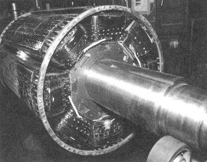
3 The two types of synchronous machines The two types of synchronous machines Round-rotor generators (or turbo-alternators) Driven by steam or gas turbines, which rotate at high speed one pair of poles (conventional thermal units) or two (nuclear units) cylindrical rotor made up of solid steel forging diameter << length (centrifugal force!) field winding made up of conductors distributed on the rotor, in milled slots even if the generator efficiency is around 99 %, the heat produced by Joule losses has to be evacuated! Large generators are cooled by hydrogen (heat evacuation 7 times better than air) or water (12 times better) flowing in the hollow stator conductors. / 6

4 The two types of synchronous machines 4 / 6

5 Salient-pole generators The synchronous machine The two types of synchronous machines Driven by hydraulic turbines (or diesel engines), which rotate at low speed many pairs of poles (at least 4) it is more convenient to have field windings concentrated and placed on the poles air gap is not constant: min. in front of a pole, max. in between two poles poles are shaped to also minimize space harmonics diameter >> length (to have space for the many poles) rotor is laminated (poles easier to construct) generators usually cooled by the flow of air around the rotor. 5 / 6

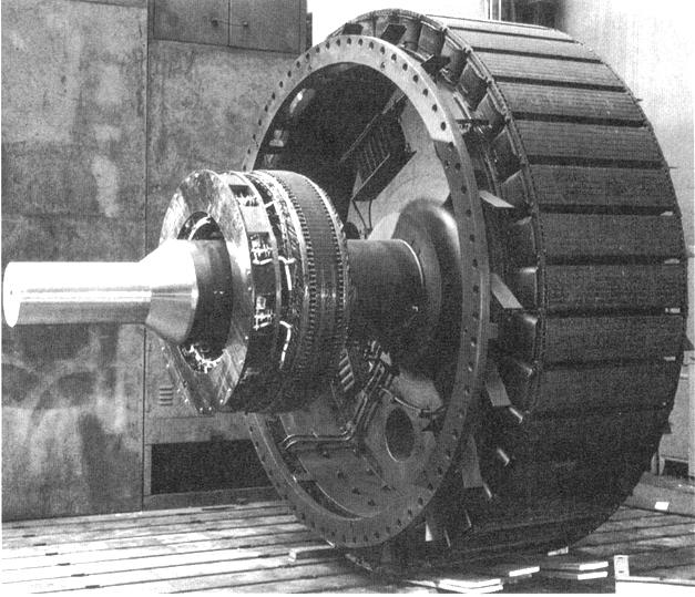
6 The two types of synchronous machines 6 / 6
7 The two types of synchronous machines Damper windings and eddy currents in rotor Damper windings (or amortisseur) round-rotor machines: copper/brass bars placed in the same slots at the field winding, and interconnected to form a damper cage (similar to the squirrel cage of an induction motor) salient-pole machines: copper/brass rods embedded in the poles and connected at their ends to rings or segments. Why? in perfect steady state: the magnetic fields produced by both the stator and the rotor are fixed relative to the rotor no current induced in dampers after a disturbance: the rotor moves with respect to stator magnetic field currents are induced in the dampers which, according to Lenz s law, create a damping torque helping the rotor to align on the stator magnetic field. Eddy currents in the rotor Round-rotor generators: the solid rotor offers a path for eddy currents, which produce an effect similar to those of amortisseurs. 7 / 6
8 Modelling of machine with magnetically coupled circuits Modelling of machine with magnetically coupled circuits Number of rotor windings = degree of sophistication of model. But: more detailed model more data are needed while measurement devices can be connected only to the field winding. Most widely used model: or 4 rotor windings: f : field winding d 1, q 1 : amortisseurs q 2 : accounts for eddy currents in rotor; not used in (laminated) salient-pole generators. 8 / 6
9 Modelling of machine with magnetically coupled circuits Remarks In the sequel, we consider: a machine with a single pair of poles, for simplicity. This does not affect the electrical behaviour of the generator (it affects the moment of inertia and the kinetic energy of rotating masses) the general case of a salient-pole machine. For a round-rotor machine: set some parameters to the same value in the d and q axes (to account for the equal air gap width) the configuration with four rotor windings (f, d 1, q 1, q 2 ). For a salient-pole generator : remove the q 2 winding. 9 / 6
10 Modelling of machine with magnetically coupled circuits Relations between voltages, currents and magnetic fluxes Stator windings: generator convention: v a (t) = R a i a (t) dψ a dt In matrix form: v b (t) = R a i b (t) dψ b dt v c (t) = R a i c (t) dψ c dt vt = RT i T d dt ψ T with RT = diag(r a R a R a ) 10 / 6
11 Modelling of machine with magnetically coupled circuits Rotor windings: motor convention: In matrix form: v f (t) = R f i f (t) + dψ f dt 0 = R d1 i d1 (t) + dψ d1 dt 0 = R q1 i q1 (t) + dψ q1 dt 0 = R q2 i q2 (t) + dψ q2 dt vr = Rr i r + d dt ψ r with Rr = diag(r f R d1 R q1 R q2 ) 11 / 6
12 Modelling of machine with magnetically coupled circuits Inductances Saturation being neglected, the fluxes vary linearly with the currents according to: [ ] [ ] [ ] ψt LTT (θ = r ) LTr (θ r ) it ψ r L T Tr (θ r ) Lrr ir LTT and LTr vary with the position θ r of the rotor but Lrr does not the components of LTT and LTr are periodic functions of θ r obviously the space harmonics in θ r are assumed negligible = sinusoidal machine assumption. 12 / 6
13 Modelling of machine with magnetically coupled circuits LTT (θ r ) = L 0 + L 1 cos 2θ r L m L 1 cos 2(θ r + π 6 ) L m L 1 cos 2(θ r π 6 ) L m L 1 cos 2(θ r + π 6 ) L 0 + L 1 cos 2(θ r 2π ) L m L 1 cos 2(θ r + π 2 ) L m L 1 cos 2(θ r π 6 ) L m L 1 cos 2(θ r + π 2 ) L 0 + L 1 cos 2(θ r + 2π ) L o, L 1, L m > 0 1 / 6
14 Modelling of machine with magnetically coupled circuits LTr (θ r ) = L af cos θ r L ad1 cos θ r L aq1 sin θ r L aq2 sin θ r L af cos(θ r 2π ) L ad1 cos(θ r 2π ) L aq1 sin(θ r 2π ) L aq2 sin(θ r 2π ) L af cos(θ r + 2π ) L ad1 cos(θ r + 2π ) L aq1 sin(θ r + 2π ) L aq2 sin(θ r + 2π ) L af, L ad1, L aq1, L aq2 > 0 14 / 6
15 Modelling of machine with magnetically coupled circuits L rr = L ff L fd1 0 0 L fd1 L d1d L q1q1 L q1q2 0 0 L q1q2 L q2q2 15 / 6
16 It is easily shown that: P P T = I P 1 = P T 16 / 6 The synchronous machine Park transformation and equations Park transformation Park transformation and equations is applied to stator variables (denoted. T ) to obtain the corresponding Park variables (denoted. P ): vp = P vt ψ P = P ψ T ip = P it 2 where P = cos θ r cos(θ r 2π ) cos(θ r + 2π ) sin θ r sin(θ r 2π ) sin(θ r + 2π ) vp = [ v d v q v o ] T ψ P = [ ψ d ψ q ψ o ] T ip = [ i d i q i o ] T
17 Park transformation and equations Interpretation Total magnetic field created by the currents i a, i b et i c : projected on d axis: k (cos θ r i a + cos(θ r 2π ) i b + cos(θ r 4π ) i c) = k 2 i d projected on q axis: k (sin θ r i a + sin(θ r 2π ) i b + sin(θ r 4π ) i c) = k 2 i q The Park transformation consists of replacing the (a, b, c) stator windings by three equivalent windings (d, q, o): the d winding is attached to the d axis the q winding is attached to the q axis the currents i d and i q produce together the same magnetic field, to the multiplicative constant / 6
18 Park equations of the synchronous machine Park transformation and equations vt = RT it d dt ψ T P 1 vp = R a I P 1 ip d dt (P 1 ψ P ) vp = R a PP 1 ip P ( d dt P 1 )ψ P PP 1 d dt ψ P = RP ip θ r Pψ P d dt ψ P with: RP = RT P = By decomposing: v d = R a i d θ r ψ q dψ d dt θ r ψ d, θ r ψ q : speed voltages v q = R a i q + θ r ψ d dψ q dt v o = R a i o dψ o dt dψ d /dt, dψ q /dt : transformer voltages 18 / 6
19 Park transformation and equations Park inductance matrix [ ψt ψ r [ P 1 ψ P [ ψ r [ ψp LPP LrP ] ] ψ r ] LPr Lrr = = = [ [ ] = LTT L T Tr LTT L T Tr LTr Lrr LTr Lrr ] [ it ir ] ] [ P 1 i P [ PL TT P 1 PLTr L T Tr P 1 Lrr ir ] [ ] ip ir ] [ = LPP LrP LPr Lrr ] [ L dd L df L dd1 L qq L qq1 L qq2 L oo L df L ff L fd1 L dd1 L fd1 L d1d1 L qq1 L q1q1 L q1q2 L qq2 L q1q2 L q2q2 ip ir ] (zero entries have been left empty for legibility) 19 / 6
20 with: The synchronous machine Park transformation and equations L dd = L 0 + L m + 2 L 1 L qq = L 0 + L m 2 L 1 L df = 2 L af L dd1 = 2 L ad1 L qq1 = 2 L aq1 L qq2 = 2 L aq2 L oo = L 0 2L m All components are independent of the rotor position θ r. That was expected! There is no magnetic coupling between d and q axes (this was already assumed in LTr and Lrr : zero mutual inductances between coils with orthogonal axes). 20 / 6
21 Park transformation and equations Leaving aside the o component and grouping (d, f, d 1 ), on one hand, and (q, q 1, q 2 ), on the other hand: v d v f 0 v q 0 0 = = R a R a R f R q1 R d1 R q2 i d i f i d1 i q i q1 i q2 + θ r ψ q 0 0 θ r ψ d 0 0 d dt d dt ψ d ψ f ψ d1 ψ q ψ q1 ψ q2 with the following flux-current relations: ψ d L dd L df L dd1 ψ f = L df L ff L fd1 ψ d1 L dd1 L fd1 L d1d1 ψ q ψ q1 ψ q2 = L qq L qq1 L qq2 L qq1 L q1q1 L q1q2 L qq2 L q1q2 L q2q2 i d i f i d1 i q i q1 i q2 21 / 6
22 Energy, power and torque Energy, power and torque Balance of power at stator: p T + p Js + dw ms dt = p r s p T : three-phase instantaneous power leaving the stator p Js : Joule losses in stator windings W ms : magnetic energy stored in the stator windings p r s : power transfer from rotor to stator (mechanical? electrical?) Three-phase instantaneous power leaving the stator : p T (t) = v a i a + v b i b + v c i c = vt T i T = vp T PP T ip = vp T i P = v d i d + v q i q + v o i o = (R a id 2 + R a iq 2 + R a io 2 dψ d dψ q dψ o ) (i d + i q + i o }{{} dt dt dt ) + θ r (ψ d i q ψ q i d ) }{{} p Js dw ms /dt p r s = θ r (ψ d i q ψ q i d ) 22 / 6
23 Energy, power and torque Balance of power at rotor: P m + p f = p Jr + dw mr dt + p r s + dw c dt P m : mechanical power provided by the turbine p f : electrical power provided to the field winding (by the excitation system) p Jr : Joule losses in the rotor windings W mr : magnetic energy stored in the rotor windings W c : kinetic energy of all rotating masses. Instantaneous power provided to field winding: p f = v f i f = v f i f + v d1 i d1 + v q1 i q1 + v q2 i q2 = (R f if 2 + R d1 id1 2 + R q1 iq1 2 + R q2 iq2) 2 dψ f dψ d1 dψ q1 + i f + i d1 + i q1 }{{} dt dt dt p Jr + i q2 dψ q2 dt } {{ } dw mr /dt P m dw c dt = θ r (ψ d i q ψ q i d ) 2 / 6
24 Energy, power and torque Equation of rotor motion: I d 2 θ r dt 2 = T m T e I : moment of inertia of all the rotating masses T m : mechanical torque applied to the rotor by the turbine T e : electromagnetic torque applied to the rotor by the generator. Multiplying the above equation by θ r : I θ r θr = θ r T m θ r T e dw c = P m θ r T e dt P m : mechanical power provided by the turbine. Hence, the (compact and elegant!) expression of the electromagnetic torque is: T e = ψ d i q ψ q i d Note. The power transfer p r s from rotor to stator is of mechanical nature only. 24 / 6
25 Energy, power and torque The various components of the torque T e T e = L dd i d i q + L df i f i q + L dd1 i d1 i q L qq i q i d L qq1 i q1 i d L qq2 i q2 i d (L dd L qq ) i d i q : synchronous torque due to rotor saliency exists in salient-pole machines only even without excitation (i f = 0), the rotor tends to align its direct axis with the axis of the rotating magnetic field created by the stator currents, offering to the latter a longer path in iron a significant fraction of the total torque in a salient-pole generator. L dd1 i d1 i q L qq1 i q1 i d L qq2 i q2 i d : damping torque due to currents induced in the amortisseurs zero in steady-state operation. L df i f i q : only component involving the field current i f the main part of the total torque in steady-state operation in steady state, it is the synchronous torque due to excitation during transients, the field winding also contributes to the damping torque. 25 / 6
26 The synchronous machine in steady state The synchronous machine in steady state Balanced three-phase currents of angular frequency ω N flow in the stator windings a direct current flows in the field winding subjected to a constant excitation voltage: i f = V f R f the rotor rotates at the synchronous speed: θ r = θ o r + ω N t no current is induced in the other rotor circuits: i d1 = i q1 = i q2 = 0 26 / 6
27 The synchronous machine in steady state Operation with stator opened Park equations: i a = i b = i c = 0 i d = i q = i o = 0 ψ d = L df i f and ψ q = 0 v d = 0 v q = ω N ψ d = ω N L df i f Getting back to the stator voltages, e.g. in phase a : 2 v a (t) = ω NL df i f sin(θr o + ω N t) = 2E q sin(θr o + ω N t) E q = ω NL df i f = e.m.f. proportional to excitation current = RMS voltage at the terminal of the opened machine. 27 / 6
28 Operation under load The synchronous machine The synchronous machine in steady state v a(t) = 2V cos(ω N t+θ) v b (t) = 2V cos(ω N t+θ 2π ) vc(t) = 2V cos(ω N t+θ+ 2π ) i a(t) = 2I cos(ω N t + ψ) i b (t) = 2I cos(ω N t + ψ 2π ) ic(t) = 2I cos(ω N t + ψ + 2π ) i d = 2 2I [cos(θ o r + ω N t) cos(ω N t + ψ) + cos(θr o + ω Nt 2π ) cos(ω Nt + ψ 2π ) + cos(θ o r + ω Nt + 2π ) cos(ω Nt + ψ + 2π )] = I [cos(θ o r + 2ω Nt + ψ) + cos(θ o r + 2ω Nt + ψ 4π ) + cos(θo r + 2ω Nt + ψ + 4π ) + cos(θ o r ψ)] = I cos(θ o r ψ) Similarly: i q = I sin(θ o r ψ) i o = 0 v d = V cos(θ o r θ) v q = V sin(θ o r θ) v o = 0 In steady-state, i d and i q are constant. This was expected! 28 / 6
29 The synchronous machine in steady state Magnetic flux in the d and q windings: The electromagnetic torque: ψ d = L dd i d + L df i f ψ q = L qq i q T e = ψ d i q ψ q i d is constant. This is important from mechanical viewpoint (no vibration!). Park equations: v d = R a i d ω N L qq i q = R a i d X q i q v q = R a i q + ω N L dd i d + ω N L df i f = R a i q + X d i d + E q v o = 0 X d = ω N L dd : direct-axis synchronous reactance X q = ω N L qq : quadrature-axis synchronous reactance 29 / 6
30 Phasor diagram The synchronous machine The synchronous machine in steady state The Park equations become: V cos(θr o θ) = R a I cos(θr o ψ) X q I sin(θr o ψ) V sin(θr o θ) = R a I sin(θr o ψ) + X d I cos(θr o ψ) + E q which are the projections on the d and q axes of the complex equation: Ē q = V + R a Ī + jx d Ī d + jx q Ī q 0 / 6
31 The synchronous machine in steady state Particular case : round-rotor machine: X d = X q = X Ē q = V + R a Ī + jx (Īd + Īq) = V + R a Ī + jx Ī Such an equivalent circuit cannot be derived for a salient-pole generator. 1 / 6
32 Powers The synchronous machine The synchronous machine in steady state Ē q = E q e j(θo r π 2 ) Ī d = I cos(θ o r ψ)e jθo r = i d e jθo r Ī q = I sin(θ o r ψ)e j(θo r π 2 ) = j i q e jθo r Ī = Ī d + Ī q = ( i d j i q )e jθo r V d = V cos(θ o r θ)e jθo r = v d e jθo r V q = V sin(θ o r θ)e j(θo r π 2 ) = j v q e jθo r V = V d + V q = ( v d j v q )e jθo r 2 / 6
33 The synchronous machine in steady state Three-phase complex power produced by the machine: S = V Ī = ( v d j v q )( i d + j i q ) = (v d j v q )(i d + j i q ) P = v d i d + v q i q Q = v d i q v q i d P and Q as functions of V, E q and the internal angle δ, assuming R a 0? v d = X q i q i q = v d X q v q = X d i d + E q i d = v q E q X d v d = V cos(θ o r θ) = V sin δ v q = V sin(θ o r θ) = V cos δ P = E qv X d sin δ+ V 2 2 ( 1 X q 1 X d ) sin 2δ Q = E qv X d Case of a round-rotor machine: P = E qv X sin δ Q = E qv X cos δ V 2 ( sin2 δ + cos2 δ ) X q X d cos δ V 2 X / 6
34 Nominal values, per unit system and orders of magnitudes Nominal values, per unit system and orders of magnitudes Stator nominal voltage U N : voltage for which the machine has been designed (in particular its insulation). The real voltage may deviate from this value by a few % nominal current I N : current for which machine has been designed (in particular the cross-section of its conductors). Maximum current that can be accepted without limit in time nominal apparent power: S N = U N I N. Conversion of parameters in per unit values: base power: S B = S N base voltage: V B = U N / base current: I B = S N /V B base impedance: Z B = VB 2/S B. 4 / 6
35 Nominal values, per unit system and orders of magnitudes Orders of magnitude (more typical of machines with a nominal power above 100 MVA) (pu values on the machine base) round-rotor salient-pole machines machines resistance R a pu direct-axis reactance X d pu pu quadrature-axis reactance X q pu pu 5 / 6
36 Park (equivalent) windings The synchronous machine Nominal values, per unit system and orders of magnitudes base power: base voltage: base current: S N VB S N = I B (single-phase formula!) VB With this choice: Similarly: i dpu = i d I = cos(θr o ψ) = I pu cos(θr o ψ) IB I B i qpu = I pu sin(θ o r ψ) v dpu = V pu cos(θ o r θ) v qpu = V pu sin(θ o r θ) Ī = Īd + Īq = (i d j i q )e jθo r V = Vd + V q = (v d j v q )e jθo r All coefficients have disappeared hence, the Park currents (resp. voltages) are exactly the projections on the machine d and q axes of the phasor Ī (resp. V ) 6 / 6
Dynamics of the synchronous machine
 ELEC0047 - Power system dynamics, control and stability Dynamics of the synchronous machine Thierry Van Cutsem t.vancutsem@ulg.ac.be www.montefiore.ulg.ac.be/~vct October 2018 1 / 38 Time constants and
Behaviour of synchronous machine during a short-circuit (a simple example of electromagnetic transients)
") ELEC0047 - Power system dynamics, control and stability (a simple example of electromagnetic transients) Thierry Van Cutsem t.vancutsem@ulg.ac.be www.montefiore.ulg.ac.be/~vct October 2018 1 / 25 Objectives
ELEC0047 - Power system dynamics, control and stability (a simple example of electromagnetic transients) Thierry Van Cutsem t.vancutsem@ulg.ac.be www.montefiore.ulg.ac.be/~vct October 2018 1 / 25 Objectives
From now, we ignore the superbar - with variables in per unit. ψ ψ. l ad ad ad ψ. ψ ψ ψ
 From now, we ignore the superbar - with variables in per unit. ψ 0 L0 i0 ψ L + L L L i d l ad ad ad d ψ F Lad LF MR if = ψ D Lad MR LD id ψ q Ll + Laq L aq i q ψ Q Laq LQ iq 41 Equivalent Circuits for
ELEC Introduction to power and energy systems. The per unit system. Thierry Van Cutsem
 ELEC0014 - Introduction to power and energy systems The per unit system Thierry Van Cutsem t.vancutsem@ulg.ac.be www.montefiore.ulg.ac.be/~vct October 2018 1 / 12 Principle The per unit system Principle
Equivalent Circuits with Multiple Damper Windings (e.g. Round rotor Machines)
") Equivalent Circuits with Multiple Damper Windings (e.g. Round rotor Machines) d axis: L fd L F - M R fd F L 1d L D - M R 1d D R fd R F e fd e F R 1d R D Subscript Notations: ( ) fd ~ field winding quantities
Equivalent Circuits with Multiple Damper Windings (e.g. Round rotor Machines) d axis: L fd L F - M R fd F L 1d L D - M R 1d D R fd R F e fd e F R 1d R D Subscript Notations: ( ) fd ~ field winding quantities
ECE 422/522 Power System Operations & Planning/ Power Systems Analysis II 2 Synchronous Machine Modeling
 ECE 422/522 Power System Operations & Planning/ Power Systems Analysis II 2 Synchronous achine odeling Spring 214 Instructor: Kai Sun 1 Outline Synchronous achine odeling Per Unit Representation Simplified
Synchronous Machines
 Synchronous Machines Synchronous generators or alternators are used to convert mechanical power derived from steam, gas, or hydraulic-turbine to ac electric power Synchronous generators are the primary
Dynamics of the synchronous machine
 ELEC0047 - Power system ynamics, control an stability Dynamics of the synchronous machine Thierry Van Cutsem t.vancutsem@ulg.ac.be www.montefiore.ulg.ac.be/~vct These slies follow those presente in course
Lecture 9: Space-Vector Models
 1 / 30 Lecture 9: Space-Vector Models ELEC-E8405 Electric Drives (5 ECTS) Marko Hinkkanen Autumn 2017 2 / 30 Learning Outcomes After this lecture and exercises you will be able to: Include the number of
Chapter 5 Three phase induction machine (1) Shengnan Li
 Shengnan Li") Chapter 5 Three phase induction machine (1) Shengnan Li Main content Structure of three phase induction motor Operating principle of three phase induction motor Rotating magnetic field Graphical representation
Chapter 5 Three phase induction machine (1) Shengnan Li Main content Structure of three phase induction motor Operating principle of three phase induction motor Rotating magnetic field Graphical representation
An Introduction to Electrical Machines. P. Di Barba, University of Pavia, Italy
 An Introduction to Electrical Machines P. Di Barba, University of Pavia, Italy Academic year 0-0 Contents Transformer. An overview of the device. Principle of operation of a single-phase transformer 3.
ROEVER COLLEGE OF ENGINEERING & TECHNOLOGY ELAMBALUR, PERAMBALUR DEPARTMENT OF ELECTRICAL AND ELECTRONICS ENGINEERING ELECTRICAL MACHINES I
 ROEVER COLLEGE OF ENGINEERING & TECHNOLOGY ELAMBALUR, PERAMBALUR-621220 DEPARTMENT OF ELECTRICAL AND ELECTRONICS ENGINEERING ELECTRICAL MACHINES I Unit I Introduction 1. What are the three basic types
Power system modelling under the phasor approximation
 ELEC0047 - Power system dynamics, control and stability Thierry Van Cutsem t.vancutsem@ulg.ac.be www.montefiore.ulg.ac.be/~vct October 2018 1 / 16 Electromagnetic transient vs. phasor-mode simulations
ECE 325 Electric Energy System Components 7- Synchronous Machines. Instructor: Kai Sun Fall 2015
 ECE 325 Electric Energy System Components 7- Synchronous Machines Instructor: Kai Sun Fall 2015 1 Content (Materials are from Chapters 16-17) Synchronous Generators Synchronous Motors 2 Synchronous Generators
EE 742 Chapter 3: Power System in the Steady State. Y. Baghzouz
 EE 742 Chapter 3: Power System in the Steady State Y. Baghzouz Transmission Line Model Distributed Parameter Model: Terminal Voltage/Current Relations: Characteristic impedance: Propagation constant: π
Lesson 17: Synchronous Machines
 Lesson 17: Synchronous Machines ET 332b Ac Motors, Generators and Power Systems Lesson 17_et332b.pptx 1 Learning Objectives After this presentation you will be able to: Explain how synchronous machines
Understanding the Inductances
 Understanding the Inductances We have identified six different inductances (or reactances) for characterizing machine dynamics. These are: d, q (synchronous), ' d, ' q (transient), '' d,'' q (subtransient)
Massachusetts Institute of Technology Department of Electrical Engineering and Computer Science Electric Machines
 Massachusetts Institute of Technology Department of Electrical Engineering and Computer Science 6.685 Electric Machines Problem Set 10 Issued November 11, 2013 Due November 20, 2013 Problem 1: Permanent
CHAPTER 2 DYNAMIC STABILITY MODEL OF THE POWER SYSTEM
 20 CHAPTER 2 DYNAMIC STABILITY MODEL OF THE POWER SYSTEM 2. GENERAL Dynamic stability of a power system is concerned with the dynamic behavior of the system under small perturbations around an operating
Revision Guide for Chapter 15
 Revision Guide for Chapter 15 Contents tudent s Checklist Revision otes Transformer... 4 Electromagnetic induction... 4 Generator... 5 Electric motor... 6 Magnetic field... 8 Magnetic flux... 9 Force on
Synchronous Machines
 Synchronous machine 1. Construction Generator Exciter View of a twopole round rotor generator and exciter. A Stator with laminated iron core C Slots with phase winding B A B Rotor with dc winding B N S
Mathematical Modelling of Permanent Magnet Synchronous Motor with Rotor Frame of Reference
 Mathematical Modelling of Permanent Magnet Synchronous Motor with Rotor Frame of Reference Mukesh C Chauhan 1, Hitesh R Khunt 2 1 P.G Student (Electrical),2 Electrical Department, AITS, rajkot 1 mcchauhan1@aits.edu.in
Step Motor Modeling. Step Motor Modeling K. Craig 1
 Step Motor Modeling Step Motor Modeling K. Craig 1 Stepper Motor Models Under steady operation at low speeds, we usually do not need to differentiate between VR motors and PM motors (a hybrid motor is
ECE 421/521 Electric Energy Systems Power Systems Analysis I 3 Generators, Transformers and the Per-Unit System. Instructor: Kai Sun Fall 2013
 ECE 41/51 Electric Energy Systems Power Systems Analysis I 3 Generators, Transformers and the Per-Unit System Instructor: Kai Sun Fall 013 1 Outline Synchronous Generators Power Transformers The Per-Unit
Modeling Free Acceleration of a Salient Synchronous Machine Using Two-Axis Theory
 1 Modeling ree Acceleration of a Salient Synchronous Machine Using Two-Axis Theory Abdullah H. Akca and Lingling an, Senior Member, IEEE Abstract This paper investigates a nonlinear simulation model of
INDUCTION MOTOR MODEL AND PARAMETERS
 APPENDIX C INDUCTION MOTOR MODEL AND PARAMETERS C.1 Dynamic Model of the Induction Motor in Stationary Reference Frame A three phase induction machine can be represented by an equivalent two phase machine
Introduction to Synchronous. Machines. Kevin Gaughan
 Introduction to Synchronous Machines Kevin Gaughan The Synchronous Machine An AC machine (generator or motor) with a stator winding (usually 3 phase) generating a rotating magnetic field and a rotor carrying
Revision Guide for Chapter 15
 Revision Guide for Chapter 15 Contents Revision Checklist Revision otes Transformer...4 Electromagnetic induction...4 Lenz's law...5 Generator...6 Electric motor...7 Magnetic field...9 Magnetic flux...
Time-Harmonic Modeling of Squirrel-Cage Induction Motors: A Circuit-Field Coupled Approach
 Time-Harmonic Modeling of Squirrel-Cage Induction Motors: A Circuit-Field Coupled Approach R. Escarela-Perez 1,3 E. Melgoza 2 E. Campero-Littlewood 1 1 División de Ciencias Básicas e Ingeniería, Universidad
Electric Machines I Three Phase Induction Motor. Dr. Firas Obeidat
 Electric Machines I Three Phase Induction Motor Dr. Firas Obeidat 1 Table of contents 1 General Principles 2 Construction 3 Production of Rotating Field 4 Why Does the Rotor Rotate 5 The Slip and Rotor
Prince Sattam bin Abdulaziz University College of Engineering. Electrical Engineering Department EE 3360 Electrical Machines (II)
") Chapter # 4 Three-Phase Induction Machines 1- Introduction (General Principles) Generally, conversion of electrical power into mechanical power takes place in the rotating part of an electric motor. In
Chapter # 4 Three-Phase Induction Machines 1- Introduction (General Principles) Generally, conversion of electrical power into mechanical power takes place in the rotating part of an electric motor. In
JRE SCHOOL OF Engineering
 JRE SCHOOL OF Engineering Class Test-1 Examinations September 2014 Subject Name Electromechanical Energy Conversion-II Subject Code EEE -501 Roll No. of Student Max Marks 30 Marks Max Duration 1 hour Date
You know for EE 303 that electrical speed for a generator equals the mechanical speed times the number of poles, per eq. (1).
.") Stability 1 1. Introduction We now begin Chapter 14.1 in your text. Our previous work in this course has focused on analysis of currents during faulted conditions in order to design protective systems
Stability 1 1. Introduction We now begin Chapter 14.1 in your text. Our previous work in this course has focused on analysis of currents during faulted conditions in order to design protective systems
Module 3 : Sequence Components and Fault Analysis
 Module 3 : Sequence Components and Fault Analysis Lecture 12 : Sequence Modeling of Power Apparatus Objectives In this lecture we will discuss Per unit calculation and its advantages. Modeling aspects
Loss analysis of a 1 MW class HTS synchronous motor
 Journal of Physics: Conference Series Loss analysis of a 1 MW class HTS synchronous motor To cite this article: S K Baik et al 2009 J. Phys.: Conf. Ser. 153 012003 View the article online for updates and
3 d Calculate the product of the motor constant and the pole flux KΦ in this operating point. 2 e Calculate the torque.
 Exam Electrical Machines and Drives (ET4117) 11 November 011 from 14.00 to 17.00. This exam consists of 5 problems on 4 pages. Page 5 can be used to answer problem 4 question b. The number before a question
Parameter Sensitivity Analysis of an Industrial Synchronous Generator
 Parameter Sensitivity Analysis of an Industrial Synchronous Generator Attila Fodor, Attila Magyar, Katalin M. Hangos Abstract A previously developed simple dynamic model of an industrial size synchronous
ECEN 667 Power System Stability Lecture 18: Voltage Stability, Load Models
 ECEN 667 Power System Stability Lecture 18: Voltage Stability, Load Models Prof. Tom Overbye Dept. of Electrical and Computer Engineering Texas A&M University, overbye@tamu.edu 1 Announcements Read Chapter
Chapter 4. Synchronous Generators. Basic Topology
 Basic Topology Chapter 4 ynchronous Generators In stator, a three-phase winding similar to the one described in chapter 4. ince the main voltage is induced in this winding, it is also called armature winding.
Generation, transmission and distribution, as well as power supplied to industrial and commercial customers uses a 3 phase system.
 Three-phase Circuits Generation, transmission and distribution, as well as power supplied to industrial and commercial customers uses a 3 phase system. Where 3 voltages are supplied of equal magnitude,
(Refer Slide Time: 00:55) Friends, today we shall continue to study about the modelling of synchronous machine. (Refer Slide Time: 01:09)
 Friends, today we shall continue to study about the modelling of synchronous machine. (Refer Slide Time: 01:09)") (Refer Slide Time: 00:55) Power System Dynamics Prof. M. L. Kothari Department of Electrical Engineering Indian Institute of Technology, Delhi Lecture - 09 Modelling of Synchronous Machine (Contd ) Friends,
(Refer Slide Time: 00:55) Power System Dynamics Prof. M. L. Kothari Department of Electrical Engineering Indian Institute of Technology, Delhi Lecture - 09 Modelling of Synchronous Machine (Contd ) Friends,
Massachusetts Institute of Technology Department of Electrical Engineering and Computer Science
 Massachusetts Institute of Technology Department of Electrical Engineering and Computer Science 6.685 Electric Machines Class Notes 4: Elementary Synchronous Machine Models September 14, 2005 c 2005 James
UNIT I INTRODUCTION Part A- Two marks questions
 ROEVER COLLEGE OF ENGINEERING & TECHNOLOGY ELAMBALUR, PERAMBALUR-621220 DEPARTMENT OF ELECTRICAL AND ELECTRONICS ENGINEERING DESIGN OF ELECTRICAL MACHINES UNIT I INTRODUCTION 1. Define specific magnetic
Synchronous machine with PM excitation Two-axis model
 Synchronous machine with PM excitation q Two-axis model q i q u q d i Q d Q D i d N S i D u d Voltage, flux-linkage and motion equations for a PM synchronous machine dd ud Ri s d q dt dq uq Ri s q d dt
Synchronous Machines
 Synchronous Machines Synchronous Machines n 1 Φ f n 1 Φ f I f I f I f damper (run-up) winding Stator: similar to induction (asynchronous) machine ( 3 phase windings that forms a rotational circular magnetic
Simulations and Control of Direct Driven Permanent Magnet Synchronous Generator
 Simulations and Control of Direct Driven Permanent Magnet Synchronous Generator Project Work Dmitry Svechkarenko Royal Institute of Technology Department of Electrical Engineering Electrical Machines and
Control of Wind Turbine Generators. James Cale Guest Lecturer EE 566, Fall Semester 2014 Colorado State University
 Control of Wind Turbine Generators James Cale Guest Lecturer EE 566, Fall Semester 2014 Colorado State University Review from Day 1 Review Last time, we started with basic concepts from physics such as
CHAPTER 5 SIMULATION AND TEST SETUP FOR FAULT ANALYSIS
 47 CHAPTER 5 SIMULATION AND TEST SETUP FOR FAULT ANALYSIS 5.1 INTRODUCTION This chapter describes the simulation model and experimental set up used for the fault analysis. For the simulation set up, the
θ α W Description of aero.m
 Description of aero.m Determination of the aerodynamic forces, moments and power by means of the blade element method; for known mean wind speed, induction factor etc. Simplifications: uniform flow (i.e.
Comparative Study of Synchronous Machine, Model 1.0 and Model 1.1 in Transient Stability Studies with and without PSS
 Comparative Study of Synchronous Machine, Model 1.0 and Model 1.1 in Transient Stability Studies with and without PSS Abhijit N Morab, Abhishek P Jinde, Jayakrishna Narra, Omkar Kokane Guide: Kiran R Patil
Equal Pitch and Unequal Pitch:
 Equal Pitch and Unequal Pitch: Equal-Pitch Multiple-Stack Stepper: For each rotor stack, there is a toothed stator segment around it, whose pitch angle is identical to that of the rotor (θs = θr). A stator
How an Induction Motor Works by Equations (and Physics)
") How an Induction Motor Works by Equations (and Physics) The magnetic field in the air gap from the voltage applied to the stator: The stator has three sets of windings that are aligned at 10 degrees to
How an Induction Motor Works by Equations (and Physics) The magnetic field in the air gap from the voltage applied to the stator: The stator has three sets of windings that are aligned at 10 degrees to
DIRECT-CURRENT MOTORS
 CHAPTER 4 DIRECT-CURRENT MOTORS Chapter Contributors Andrew E. Miller Earl F. Richards Alan W. Yeadon William H. Yeadon This chapter covers methods of calculating performance for direct-current (dc) mechanically
Analytical Model for Sizing the Magnets of Permanent Magnet Synchronous Machines
 Journal of Electrical Engineering 3 (2015) 134-141 doi: 10.17265/2328-2223/2015.03.004 D DAVID PUBLISHING Analytical Model for Sizing Magnets of Permanent Magnet Synchronous Machines George Todorov and
The Linear Induction Motor, a Useful Model for examining Finite Element Methods on General Induction Machines
 The Linear Induction Motor, a Useful Model for examining Finite Element Methods on General Induction Machines Herbert De Gersem, Bruno Renier, Kay Hameyer and Ronnie Belmans Katholieke Universiteit Leuven
Motor-CAD combined electromagnetic and thermal model (January 2015)
") Motor-CAD combined electromagnetic and thermal model (January 2015) Description The Motor-CAD allows the machine performance, losses and temperatures to be calculated for a BPM machine. In this tutorial
Motor-CAD combined electromagnetic and thermal model (January 2015) Description The Motor-CAD allows the machine performance, losses and temperatures to be calculated for a BPM machine. In this tutorial
ECE 692 Advanced Topics on Power System Stability 2 Power System Modeling
 ECE 692 Avance Topics on Power System Stability 2 Power System Moeling Spring 2016 Instructor: Kai Sun 1 Outline Moeling of synchronous generators for Stability Stuies Moeling of loas Moeling of frequency
Tutorial 1 (EMD) Rotary field winding
 Rotary field winding") Tutorial 1 (EMD) Rotary field winding The unchorded two-layer three-phase winding of a small synchronous fan drive for a computer has the following parameters: number of slots per pole and phase q = 1,
Tutorial 1 (EMD) Rotary field winding The unchorded two-layer three-phase winding of a small synchronous fan drive for a computer has the following parameters: number of slots per pole and phase q = 1,
Chapter 15 Magnetic Circuits and Transformers
 Chapter 15 Magnetic Circuits and Transformers Chapter 15 Magnetic Circuits and Transformers 1. Understand magnetic fields and their interactio with moving charges. 2. Use the right-hand rule to determine
Texas A & M University Department of Mechanical Engineering MEEN 364 Dynamic Systems and Controls Dr. Alexander G. Parlos
 Texas A & M University Department of Mechanical Engineering MEEN 364 Dynamic Systems and Controls Dr. Alexander G. Parlos Lecture 6: Modeling of Electromechanical Systems Principles of Motor Operation
CURRENT-CARRYING CONDUCTORS / MOVING CHARGES / CHARGED PARTICLES IN CIRCULAR ORBITS
 PHYSICS A2 UNIT 4 SECTION 4: MAGNETIC FIELDS CURRENT-CARRYING CONDUCTORS / MOVING CHARGES / CHARGED PARTICLES IN CIRCULAR ORBITS # Questions MAGNETIC FLUX DENSITY 1 What is a magnetic field? A region in
The synchronous machine (SM) in the power system (2) (Where does the electricity come from)?
 in the power system (2) (Where does the electricity come from)?") 1 The synchronous machine (SM) in the power system (2) (Where does the electricity come from)? 2 Lecture overview Synchronous machines with more than 2 magnetic poles The relation between the number of
1 The synchronous machine (SM) in the power system (2) (Where does the electricity come from)? 2 Lecture overview Synchronous machines with more than 2 magnetic poles The relation between the number of
Analytical and numerical computation of the no-load magnetic field in induction motors
 Analytical and numerical computation of the no-load induction motors Dan M. Ionel University of Glasgow, Glasgow, Scotland, UK and Mihai V. Cistelecan Research Institute for Electrical Machines, Bucharest
Magnetic Leakage Fields and End Region Eddy Current Power Losses in Synchronous Generators
 Digital Comprehensive Summaries of Uppsala Dissertations from the Faculty of Science and Technology 1575 Magnetic Leakage Fields and End Region Eddy Current Power Losses in Synchronous Generators BIRGER
Lecture 7: Synchronous Motor Drives
 1 / 46 Lecture 7: Synchronous Motor Drives ELEC-E8402 Control of Electric Drives and Power Converters (5 ECTS) Marko Hinkkanen Spring 2017 2 / 46 Learning Outcomes After this lecture and exercises you
Symmetrical Components Fall 2007
 0.1 Variables STEADYSTATE ANALYSIS OF SALIENT-POLESYNCHRONOUS GENERATORS This paper is intended to provide a procedure for calculating the internal voltage of a salientpole synchronous generator given
Electromagnetic Induction and Faraday s Law
 Electromagnetic Induction and Faraday s Law Induced EMF Almost 200 years ago, Faraday looked for evidence that a magnetic field would induce an electric current with this apparatus: He found no evidence
Energy Converters. CAD and System Dynamics
 Institut für Elektrische Energiewandlung Energy Converters CAD and System Dynamics - Tutorials - Issue 2017/2018 M.Sc. Sascha Neusüs / M.Sc. Marcel Lehr Professor Dr.-Ing. habil. Dr. h.c. Andreas Binder
Dynamic Modeling of Surface Mounted Permanent Synchronous Motor for Servo motor application
 797 Dynamic Modeling of Surface Mounted Permanent Synchronous Motor for Servo motor application Ritu Tak 1, Sudhir Y Kumar 2, B.S.Rajpurohit 3 1,2 Electrical Engineering, Mody University of Science & Technology,
Induction Motors. The single-phase induction motor is the most frequently used motor in the world
 Induction Motor The single-phase induction motor is the most frequently used motor in the world Most appliances, such as washing machines and refrigerators, use a single-phase induction machine Highly
Introduction. Energy is needed in different forms: Light bulbs and heaters need electrical energy Fans and rolling miles need mechanical energy
 Introduction Energy is needed in different forms: Light bulbs and heaters need electrical energy Fans and rolling miles need mechanical energy What does AC and DC stand for? Electrical machines Motors
ELECTRICALMACHINES-I QUESTUION BANK
 ELECTRICALMACHINES-I QUESTUION BANK UNIT-I INTRODUCTION OF MAGNETIC MATERIAL PART A 1. What are the three basic rotating Electric machines? 2. Name the three materials used in machine manufacture. 3. What
THE DYNAMIC BEHAVIOUR OF SYNCHRONOUS AND ASYNCHRONOUS MACHINES WITH TWO-SIDE ASYMMETRY CONSIDERING SATURATION
 THE DYNAMIC BEHAVIOUR OF SYNCHRONOUS AND ASYNCHRONOUS MACHINES WITH TWO-SIDE ASYMMETRY CONSIDERING SATURATION By P. VAS Department of Electric IIIachines. Technical University. Bndapest Received February
Generalized Theory of Electrical Machines- A Review
 Generalized Theory of Electrical Machines- A Review Dr. Sandip Mehta Department of Electrical and Electronics Engineering, JIET Group of Institutions, Jodhpur Abstract:-This paper provides an overview
MODELING AND SIMULATION OF ENGINE DRIVEN INDUCTION GENERATOR USING HUNTING NETWORK METHOD
 MODELING AND SIMULATION OF ENGINE DRIVEN INDUCTION GENERATOR USING HUNTING NETWORK METHOD K. Ashwini 1, G. N. Sreenivas 1 and T. Giribabu 2 1 Department of Electrical and Electronics Engineering, JNTUH
Review of Basic Electrical and Magnetic Circuit Concepts EE
 Review of Basic Electrical and Magnetic Circuit Concepts EE 442-642 Sinusoidal Linear Circuits: Instantaneous voltage, current and power, rms values Average (real) power, reactive power, apparent power,
EEE3405 ELECTRICAL ENGINEERING PRINCIPLES 2 - TEST
 ATTEMPT ALL QUESTIONS (EACH QUESTION 20 Marks, FULL MAKS = 60) Given v 1 = 100 sin(100πt+π/6) (i) Find the MS, period and the frequency of v 1 (ii) If v 2 =75sin(100πt-π/10) find V 1, V 2, 2V 1 -V 2 (phasor)
Synchronous Machines - Structure
 Synchronou Machine - Structure Synchronou Machine - Structure rotate at contant peed. primary energy converion device of the word electric power ytem. both generator and motor operation can draw either
Modeling of Symmetrical Squirrel Cage Induction Machine with MatLab Simulink
 Modeling of Symmetrical Squirrel Cage Induction Machine with MatLab Simulink Marcus Svoboda *, Lucian Tutelea *, Gheorghe Madescu **, Marius Biriescu *, Martian Mot ** * University POLITEHNICA Timisoara/Electrical
ECE 585 Power System Stability
 Homework 1, Due on January 29 ECE 585 Power System Stability Consider the power system below. The network frequency is 60 Hz. At the pre-fault steady state (a) the power generated by the machine is 400
Design of Synchronous Machines
 Design of Synchronous Machines Introduction Synchronous machines are AC machines that have a field circuit supplied by an external DC source. Synchronous machines are having two major parts namely stationary
CHAPTER 3 INFLUENCE OF STATOR SLOT-SHAPE ON THE ENERGY CONSERVATION ASSOCIATED WITH THE SUBMERSIBLE INDUCTION MOTORS
 38 CHAPTER 3 INFLUENCE OF STATOR SLOT-SHAPE ON THE ENERGY CONSERVATION ASSOCIATED WITH THE SUBMERSIBLE INDUCTION MOTORS 3.1 INTRODUCTION The electric submersible-pump unit consists of a pump, powered by
Generators for wind power conversion
 Generators for wind power conversion B. G. Fernandes Department of Electrical Engineering Indian Institute of Technology, Bombay Email : bgf@ee.iitb.ac.in Outline of The Talk Introduction Constant speed
Electromagnetic Oscillations and Alternating Current. 1. Electromagnetic oscillations and LC circuit 2. Alternating Current 3.
 Electromagnetic Oscillations and Alternating Current 1. Electromagnetic oscillations and LC circuit 2. Alternating Current 3. RLC circuit in AC 1 RL and RC circuits RL RC Charging Discharging I = emf R
UNIT-I INTRODUCTION. 1. State the principle of electromechanical energy conversion.
 UNIT-I INTRODUCTION 1. State the principle of electromechanical energy conversion. The mechanical energy is converted in to electrical energy which takes place through either by magnetic field or electric
Dynamic Behavior of Three phase Inductions Motors as Loads in an Electric Power System with Distributed Generation, a Case of Study.
 Dynamic Behavior of Three phase Inductions Motors as Loads in an Electric Power System with Distributed Generation, a Case of Study. Marcelo Rodrigo García Saquicela, Ernesto Ruppert Filho, José Luis Azcue
A GENERALISED OPERATIONAL EQUIVALENT CIRCUIT OF INDUCTION MACHINES FOR TRANSIENT/DYNAMIC STUDIES UNDER DIFFERENT OPERATING CONDITIONS
 A GENERALISED OPERATIONAL EQUIVALENT CIRCUIT OF INDUCTION MACHINES FOR TRANSIENT/DYNAMIC STUDIES UNDER DIFFERENT OPERATING CONDITIONS S. S. Murthy Department of Electrical Engineering Indian Institute
Electrical Machines and Energy Systems: Operating Principles (Part 1) SYED A Rizvi
 SYED A Rizvi") Electrical Machines and Energy Systems: Operating Principles (Part 1) SYED A Rizvi AC Machines Operating Principles: Rotating Magnetic Field The key to the functioning of AC machines is the rotating magnetic
Electrical Machines and Energy Systems: Operating Principles (Part 1) SYED A Rizvi AC Machines Operating Principles: Rotating Magnetic Field The key to the functioning of AC machines is the rotating magnetic
Lecture 1: Induction Motor
 1 / 22 Lecture 1: Induction Motor ELEC-E8402 Control of Electric Drives and Power Converters (5 ECTS) Marko Hinkkanen Aalto University School of Electrical Engineering Spring 2016 2 / 22 Learning Outcomes
RLC Circuit (3) We can then write the differential equation for charge on the capacitor. The solution of this differential equation is
 We can then write the differential equation for charge on the capacitor. The solution of this differential equation is") RLC Circuit (3) We can then write the differential equation for charge on the capacitor The solution of this differential equation is (damped harmonic oscillation!), where 25 RLC Circuit (4) If we charge
RLC Circuit (3) We can then write the differential equation for charge on the capacitor The solution of this differential equation is (damped harmonic oscillation!), where 25 RLC Circuit (4) If we charge
ELECTRIC POWER CIRCUITS BASIC CONCEPTS AND ANALYSIS
 Contents ELEC46 Power ystem Analysis Lecture ELECTRC POWER CRCUT BAC CONCEPT AND ANALY. Circuit analysis. Phasors. Power in single phase circuits 4. Three phase () circuits 5. Power in circuits 6. ingle
Balanced three-phase systems and operation
 ELEC0014 - Introduction to power and energy systems Balanced three-phase systems and operation Thierry Van Cutsem t.vancutsem@ulg.ac.be www.montefiore.ulg.ac.be/~vct October 2017 1 / 17 system used for
Transformer Fundamentals
 Transformer Fundamentals 1 Introduction The physical basis of the transformer is mutual induction between two circuits linked by a common magnetic field. Transformer is required to pass electrical energy
PESIT Bangalore South Campus Hosur road, 1km before Electronic City, Bengaluru -100 Department of Electronics & Communication Engineering
 QUESTION PAPER INTERNAL ASSESSMENT TEST 2 Date : /10/2016 Marks: 0 Subject & Code: BASIC ELECTRICAL ENGINEERING -15ELE15 Sec : F,G,H,I,J,K Name of faculty : Dhanashree Bhate, Hema B, Prashanth V Time :
AC Induction Motor Stator Resistance Estimation Algorithm
 7th WSEAS International Conference on Electric Power Systems, High Voltages, Electric Machines, Venice, Italy, November 21-23, 27 86 AC Induction Motor Stator Resistance Estimation Algorithm PETR BLAHA
Transient Analysis of Three Phase Squirrel Cage Induction Machine using Matlab
 Transient Analysis of Three Phase Squirrel Cage Induction Machine using Matlab Mukesh Kumar Arya*, Dr.Sulochana Wadhwani** *( Department of Electrical Engineering, Madhav Institute of Technology & Science,
SECTION - I. PULL-IN-OPERATION Op SYNCHRONOUS MOTORS
 SECTION - I PULL-IN-OPERATION Op SYNCHRONOUS MOTORS 14 S 1.1 INTRODUCTION The starting of synchronous, reluctance and permanent magnet synchronous motors is normally carried out by damper winding. The
Small-Signal Analysis of a Saturated Induction Motor
 1 Small-Signal Analysis of a Saturated Induction Motor Mikaela Ranta, Marko Hinkkanen, Anna-Kaisa Repo, and Jorma Luomi Helsinki University of Technology Department of Electrical Engineering P.O. Box 3,
Notes 18 Faraday s Law
 EE 3318 Applied Electricity and Magnetism Spring 2018 Prof. David R. Jackson Dept. of EE Notes 18 Faraday s Law 1 Example (cont.) Find curl of E from a static point charge q y E q = rˆ 2 4πε0r x ( E sinθ
Information for Physics 1201 Midterm I Wednesday, February 20
 My lecture slides are posted at http://www.physics.ohio-state.edu/~humanic/ Information for Physics 1201 Midterm I Wednesday, February 20 1) Format: 10 multiple choice questions (each worth 5 points) and