How to measure complex impedance at high frequencies where phase measurement is unreliable.
|
|
|
- Francine Holt
- 5 years ago
- Views:
Transcription
1 Objectives In this course you will learn the following Various applications of transmission lines. How to measure complex impedance at high frequencies where phase measurement is unreliable. How and why to use sections of transmission line as reactive elements in the high frequency circuits. Use of Smith chart and to design transmission line sections for realizing reactive impedances.


2 Measurement of Unknown Impedance The unknown impedance which is to be measured is connected at the end of the transmission line as shown in Figure below. The transmission line is excited with a source of desired frequency. From the standing wave pattern, three quantities, namely the maximum voltage, minimum voltage, and the distance of the voltage minimum from the load is measured. The ratio of and gives the VSWR on the line. We know that at point B on the transmission line where the voltage is minimum, the impedance is real and its value is. The impedance is nothing but the transformed value of the load impedance. We can therefore obtain the unknown impedance by transforming back from point B to point A. Let the distance of the voltage minimum from the load be. Since the transformation from B to A is away from the generator, the distance BA is negative. The unknown impedance therefore is Substituting for, we get Separating real and imaginary parts we get
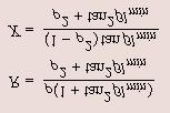
3

4 Measurement of Unknown Impedance (Practical Consideration) While practically implementing the above scheme one would also notice that invariably the location of unknown impedance is not precisely defined. As a result the measurement of in the load impedance. may have some error which in turn will result into an error To overcome this problem the measurement is carried out in two steps. First, the standing wave pattern is obtained with the unknown load as explained above. Now replace the unknown impedance by an ideal short-circuit and obtain the standing wave pattern again. The two standing wave patterns are shown as below At the short circuit point (which is also the location of the unknown impedance) the voltage is zero. The voltage is also zero at points which are multiple of away from it. i.e., at point C, E etc. The points C, E etc represent impedance conditions identical to that at A, that is, the impedance at C or E is equal to the unknown impedance. The unknown impedance therefore can be obtained by transforming impedance at B or D to point C. If impedance is transformed from D to C the distance is negative, whereas if the transformation is made from B to C the distance is positive. The unknown impedance therefore can be evaluated as One can note here that. In the impedance calculation either of or can be used. As long as the sign of the distance is taken correctly it does not matter which of the minima is taken for impedance transformation.


5 Transmission Line as a Circuit Element At frequencies of hundreds and thousands of MHz where lumped elements are hard to realize, the use of sections of transmission line as reactive elements may be more convenient. The turns in the wire of the inductor have small distributed capacitors. As the frequency increases, the capacitance begins to play a role in the response of the circuit and beyond the resonant frequency, the capacitance predominates the response. That is the inductance coil effectively behaves like a capacitor. Similarly, for a capacitance, there exist lead inductance. As the frequency increases, the lead inductance starts dominating over the capacitance and beyond the resonant frequency of the LC combination, the capacitor effectively behaves like an inductor. So, it is clear that at high frequencies, realization of reactive element is not that simple. On the other hand at high frequencies, the wavelength and the length of the transmission line section reduces and becomes more manageable.


6 Use of Smith Chart for calculating and From the impedance relation we can see that if a line of length is terminated in a short circuit or open circuit (shown in Figure below) the input impedance of the transmission line is purely reactive. The input impedance of a loss-less line can be written as Since the range of 'tan' and 'cot' functions is from to, any reactance can be realized by proper choice of. Moreover, any reactance can be realized by either open or short circuit termination. This is a very useful feature because depending upon the transmission line structure, terminating one way may be easier than other. For example, for a microstrip type line ( see in later section), realizing an open circuit is easier as short circuit would require drilling a hole in the substrate. Now if a reactance is to be realized in a high frequency circuit one can use a short circuited line of length or an open circuited line of length given by Smith chart can be used to find or as follows: Choose suitable characteristics impedance of the line, Normalize the reactance to be realized (X) by to give normalized reactance. (a) Mark the reactance jx to be realized on the Smith chart to get point 'X' in Figure. (b) (c) Move in anticlockwise direction from point X to the short circuit (SC) point on the Smith chart to get below). Move from X in the anticlockwise direction upto open circuit (OC) to get as indicated in Figure. (see Figure (d) Note here that instead of reactance if we had to realize a normalized susceptance b, the procedure is identical except that SC and OC points are interchanged.
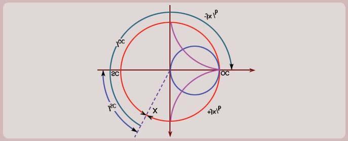
7

8 Line length and their Equivalent Reactants The following figure shows the range of transmission line lengths and the corresponding reactances which can be realized at the input terminals of the line.
9 Recap In this course you have learnt the following Various applications of transmission lines. How to measure complex impedance at high frequencies where phase measurement is unreliable. How and why to use sections of transmission line as reactive elements in the high frequency circuits. Use of Smith chart and to design transmission line sections for realizing reactive impedances.
Module 2 : Transmission Lines. Lecture 10 : Transmisssion Line Calculations Using Smith Chart. Objectives. In this course you will learn the following
 Objectives In this course you will learn the following What is a constant VSWR circle on the - plane? Properties of constant VSWR circles. Calculations of load reflection coefficient. Calculation of reflection
TRANSMISSION LINES AND MATCHING
 TRANSMISSION LINES AND MATCHING for High-Frequency Circuit Design Elective by Michael Tse September 2003 Contents Basic models The Telegrapher s equations and solutions Transmission line equations The
AC Circuits Homework Set
 Problem 1. In an oscillating LC circuit in which C=4.0 μf, the maximum potential difference across the capacitor during the oscillations is 1.50 V and the maximum current through the inductor is 50.0 ma.
y(d) = j
 = j") Problem 2.66 A 0-Ω transmission line is to be matched to a computer terminal with Z L = ( j25) Ω by inserting an appropriate reactance in parallel with the line. If f = 800 MHz and ε r = 4, determine the
Problem 2.66 A 0-Ω transmission line is to be matched to a computer terminal with Z L = ( j25) Ω by inserting an appropriate reactance in parallel with the line. If f = 800 MHz and ε r = 4, determine the
Impedance Matching. Generally, Z L = R L + jx L, X L 0. You need to turn two knobs to achieve match. Example z L = 0.5 j
 Impedance Matching Generally, Z L = R L + jx L, X L 0. You need to turn two knobs to achieve match. Example z L = 0.5 j This time, we do not want to cut the line to insert a matching network. Instead,
TC 412 Microwave Communications. Lecture 6 Transmission lines problems and microstrip lines
 TC 412 Microwave Communications Lecture 6 Transmission lines problems and microstrip lines RS 1 Review Input impedance for finite length line Quarter wavelength line Half wavelength line Smith chart A
Transmission Lines. Plane wave propagating in air Y unguided wave propagation. Transmission lines / waveguides Y. guided wave propagation
 Transmission Lines Transmission lines and waveguides may be defined as devices used to guide energy from one point to another (from a source to a load). Transmission lines can consist of a set of conductors,
Lecture 14 Date:
 Lecture 14 Date: 18.09.2014 L Type Matching Network Examples Nodal Quality Factor T- and Pi- Matching Networks Microstrip Matching Networks Series- and Shunt-stub Matching L Type Matching Network (contd.)
Imaginary Impedance Axis. Real Impedance Axis. Smith Chart. The circles, tangent to the right side of the chart, are constant resistance circles
 The Smith Chart The Smith Chart is simply a graphical calculator for computing impedance as a function of reflection coefficient. Many problems can be easily visualized with the Smith Chart The Smith chart
ECE 107: Electromagnetism
 ECE 107: Electromagnetism Set 2: Transmission lines Instructor: Prof. Vitaliy Lomakin Department of Electrical and Computer Engineering University of California, San Diego, CA 92093 1 Outline Transmission
ECE 391 supplemental notes - #11. Adding a Lumped Series Element
 ECE 391 supplemental notes - #11 Adding a umped Series Element Consider the following T-line circuit: Z R,1! Z,2! Z z in,1 = r in,1 + jx in,1 Z in,1 = z in,1 Z,1 z = Z Z,2 zin,2 = r in,2 + jx in,2 z,1
6-1 Chapter 6 Transmission Lines
 6-1 Chapter 6 Transmission ines ECE 3317 Dr. Stuart A. ong 6-2 General Definitions p.133 6-3 Voltage V( z) = α E ds ( C z) 1 C t t ( a) Current I( z) = α H ds ( C0 closed) 2 C 0 ( b) http://www.cartoonstock.com
Annexure-I. network acts as a buffer in matching the impedance of the plasma reactor to that of the RF
 Annexure-I Impedance matching and Smith chart The output impedance of the RF generator is 50 ohms. The impedance matching network acts as a buffer in matching the impedance of the plasma reactor to that
) Rotate L by 120 clockwise to obtain in!! anywhere between load and generator: rotation by 2d in clockwise direction. d=distance from the load to the
 Rotate L by 120 clockwise to obtain in!! anywhere between load and generator: rotation by 2d in clockwise direction. d=distance from the load to the") 3.1 Smith Chart Construction: Start with polar representation of. L ; in on lossless lines related by simple phase change ) Idea: polar plot going from L to in involves simple rotation. in jj 1 ) circle
3.1 Smith Chart Construction: Start with polar representation of. L ; in on lossless lines related by simple phase change ) Idea: polar plot going from L to in involves simple rotation. in jj 1 ) circle
High Speed Communication Circuits and Systems Lecture 4 Generalized Reflection Coefficient, Smith Chart, Integrated Passive Components
 High Speed Communication Circuits and Systems Lecture 4 Generalized Reflection Coefficient, Smith Chart, Integrated Passive Components Michael H. Perrott February 11, 2004 Copyright 2004 by Michael H.
Module 2 : Transmission Lines. Lecture 1 : Transmission Lines in Practice. Objectives. In this course you will learn the following
 Objectives In this course you will learn the following Point 1 Point 2 Point 3 Point 4 Point 5 Point 6 Point 7 Point 8 Point 9 Point 10 Point 11 Point 12 Various Types Of Transmission Line Explanation:
CHAPTER 22 ELECTROMAGNETIC INDUCTION
 CHAPTER 22 ELECTROMAGNETIC INDUCTION PROBLEMS 47. REASONING AND Using Equation 22.7, we find emf 2 M I or M ( emf 2 ) t ( 0.2 V) ( 0.4 s) t I (.6 A) ( 3.4 A) 9.3 0 3 H 49. SSM REASONING AND From the results
Sinusoidal Steady State Analysis (AC Analysis) Part I
 Part I") Sinusoidal Steady State Analysis (AC Analysis) Part I Amin Electronics and Electrical Communications Engineering Department (EECE) Cairo University elc.n102.eng@gmail.com http://scholar.cu.edu.eg/refky/
Sinusoidal Steady State Analysis (AC Analysis) Part I Amin Electronics and Electrical Communications Engineering Department (EECE) Cairo University elc.n102.eng@gmail.com http://scholar.cu.edu.eg/refky/
MODULE-4 RESONANCE CIRCUITS
 Introduction: MODULE-4 RESONANCE CIRCUITS Resonance is a condition in an RLC circuit in which the capacitive and inductive Reactance s are equal in magnitude, there by resulting in purely resistive impedance.
Berkeley. The Smith Chart. Prof. Ali M. Niknejad. U.C. Berkeley Copyright c 2017 by Ali M. Niknejad. September 14, 2017
 Berkeley The Smith Chart Prof. Ali M. Niknejad U.C. Berkeley Copyright c 17 by Ali M. Niknejad September 14, 17 1 / 29 The Smith Chart The Smith Chart is simply a graphical calculator for computing impedance
Transmission Lines in the Frequency Domain
 Berkeley Transmission Lines in the Frequency Domain Prof. Ali M. Niknejad U.C. Berkeley Copyright c 2016 by Ali M. Niknejad August 30, 2017 1 / 38 Why Sinusoidal Steady-State? 2 / 38 Time Harmonic Steady-State
AC Circuit. a) Learn the usage of frequently used AC instrument equipment (AC voltmeter, AC ammeter, power meter).
 Learn the usage of frequently used AC instrument equipment (AC voltmeter, AC ammeter, power meter).") Experiment 5:Measure the Equivalent arameters in the AC Circuit 1. urpose a) Learn the usage of frequently used AC instrument equipment (AC voltmeter, AC ammeter, power meter). b) Know the basic operational
Experiment 5:Measure the Equivalent arameters in the AC Circuit 1. urpose a) Learn the usage of frequently used AC instrument equipment (AC voltmeter, AC ammeter, power meter). b) Know the basic operational
ECE 604, Lecture 13. October 16, 2018
 ECE 604, Lecture 13 October 16, 2018 1 Introduction In this lecture, we will cover the following topics: Terminated Transmission Line Smith Chart Voltage Standing Wave Ratio (VSWR) Additional Reading:
ECE357H1S ELECTROMAGNETIC FIELDS TERM TEST 1. 8 February 2016, 19:00 20:00. Examiner: Prof. Sean V. Hum
 UNIVERSITY OF TORONTO FACULTY OF APPLIED SCIENCE AND ENGINEERING The Edward S. Rogers Sr. Department of Electrical and Computer Engineering ECE57HS ELECTROMAGNETIC FIELDS TERM TEST 8 February 6, 9:00 :00
ECE145A/218A Course Notes
 ECE145A/218A Course Notes Last note set: Introduction to transmission lines 1. Transmission lines are a linear system - superposition can be used 2. Wave equation permits forward and reverse wave propagation
Solutions to Problems in Chapter 6
 Appendix F Solutions to Problems in Chapter 6 F.1 Problem 6.1 Short-circuited transmission lines Section 6.2.1 (book page 193) describes the method to determine the overall length of the transmission line
Problem 1 Γ= = 0.1λ = max VSWR = 13
 Smith Chart Problems 1. The 0:1 length line shown has a characteristic impedance of 50 and is terminated with a load impedance of Z =5+j25. (a) ocate z = Z Z 0 =0:1+j0:5 onthe Smith chart. See the point
Transmission Line Theory
 S. R. Zinka zinka@vit.ac.in School of Electronics Engineering Vellore Institute of Technology April 26, 2013 Outline 1 Free Space as a TX Line 2 TX Line Connected to a Load 3 Some Special Cases 4 Smith
PHY3128 / PHYM203 (Electronics / Instrumentation) Transmission Lines
 Transmission Lines") Transmission Lines Introduction A transmission line guides energy from one place to another. Optical fibres, waveguides, telephone lines and power cables are all electromagnetic transmission lines. are
Transmission Lines Introduction A transmission line guides energy from one place to another. Optical fibres, waveguides, telephone lines and power cables are all electromagnetic transmission lines. are
Lecture 12 Date:
 Lecture 12 Date: 09.02.2017 Microstrip Matching Networks Series- and Shunt-stub Matching Quarter Wave Impedance Transformer Microstrip Line Matching Networks In the lower RF region, its often a standard
Transformer. Transformer comprises two or more windings coupled by a common magnetic circuit (M.C.).
.") . Transformers Transformer Transformer comprises two or more windings coupled by a common magnetic circuit (M.C.). f the primary side is connected to an AC voltage source v (t), an AC flux (t) will be
. Transformers Transformer Transformer comprises two or more windings coupled by a common magnetic circuit (M.C.). f the primary side is connected to an AC voltage source v (t), an AC flux (t) will be
Alternating Current Circuits
 Alternating Current Circuits AC Circuit An AC circuit consists of a combination of circuit elements and an AC generator or source. The output of an AC generator is sinusoidal and varies with time according
Microwave Circuits Design
 The Smith Chart: The Smith chart is a graphical aide used to simplify the solution of Tx-line problems More importantly, the Smith chart allows us to visualize the periodic nature of the line impedance
mywbut.com Lesson 16 Solution of Current in AC Parallel and Seriesparallel
 esson 6 Solution of urrent in Parallel and Seriesparallel ircuits n the last lesson, the following points were described:. How to compute the total impedance/admittance in series/parallel circuits?. How
RLC Circuit (3) We can then write the differential equation for charge on the capacitor. The solution of this differential equation is
 We can then write the differential equation for charge on the capacitor. The solution of this differential equation is") RLC Circuit (3) We can then write the differential equation for charge on the capacitor The solution of this differential equation is (damped harmonic oscillation!), where 25 RLC Circuit (4) If we charge
RLC Circuit (3) We can then write the differential equation for charge on the capacitor The solution of this differential equation is (damped harmonic oscillation!), where 25 RLC Circuit (4) If we charge
Single Phase Parallel AC Circuits
 Single Phase Parallel AC Circuits 1 Single Phase Parallel A.C. Circuits (Much of this material has come from Electrical & Electronic Principles & Technology by John Bird) n parallel a.c. circuits similar
LCR Series Circuits. AC Theory. Introduction to LCR Series Circuits. Module. What you'll learn in Module 9. Module 9 Introduction
 Module 9 AC Theory LCR Series Circuits Introduction to LCR Series Circuits What you'll learn in Module 9. Module 9 Introduction Introduction to LCR Series Circuits. Section 9.1 LCR Series Circuits. Amazing
Assessment Schedule 2015 Physics: Demonstrate understanding of electrical systems (91526)
") NCEA Level 3 Physics (91526) 2015 page 1 of 6 Assessment Schedule 2015 Physics: Demonstrate understanding of electrical systems (91526) Evidence Q Evidence Achievement Achievement with Merit Achievement
NCEA Level 3 Physics (91526) 2015 page 1 of 6 Assessment Schedule 2015 Physics: Demonstrate understanding of electrical systems (91526) Evidence Q Evidence Achievement Achievement with Merit Achievement
LINEAR CIRCUIT ANALYSIS (EED) U.E.T. TAXILA 09
 U.E.T. TAXILA 09") LINEAR CIRCUIT ANALYSIS (EED) U.E.T. TAXILA 09 ENGR. M. MANSOOR ASHRAF INTRODUCTION Thus far our analysis has been restricted for the most part to dc circuits: those circuits excited by constant or time-invariant
LINEAR CIRCUIT ANALYSIS (EED) U.E.T. TAXILA 09 ENGR. M. MANSOOR ASHRAF INTRODUCTION Thus far our analysis has been restricted for the most part to dc circuits: those circuits excited by constant or time-invariant
Chapter 33. Alternating Current Circuits
 Chapter 33 Alternating Current Circuits 1 Capacitor Resistor + Q = C V = I R R I + + Inductance d I Vab = L dt AC power source The AC power source provides an alternative voltage, Notation - Lower case
ANTENNAS and MICROWAVES ENGINEERING (650427)
") Philadelphia University Faculty of Engineering Communication and Electronics Engineering ANTENNAS and MICROWAVES ENGINEERING (65427) Part 2 Dr. Omar R Daoud 1 General Considerations It is a two-port network
Philadelphia University Faculty of Engineering Communication and Electronics Engineering ANTENNAS and MICROWAVES ENGINEERING (65427) Part 2 Dr. Omar R Daoud 1 General Considerations It is a two-port network
HOW TO SOLVE YOUR ANTENNA MATCHING PROBLEMS
 HOW TO SOLVE YOUR ANTENNA MATCHING PROBLEMS John Sexton, G4CNN. Reprinted from Echelford Amateur Radio Society Newsletter for November 1978. Introduction. In January 1977 there appeared in RADCOM an article
Resonant Matching Networks
 Chapter 1 Resonant Matching Networks 1.1 Introduction Frequently power from a linear source has to be transferred into a load. If the load impedance may be adjusted, the maximum power theorem states that
Dr. Vahid Nayyeri. Microwave Circuits Design
 Lect. 8: Microwave Resonators Various applications: including filters, oscillators, frequency meters, and tuned amplifiers, etc. microwave resonators of all types can be modelled in terms of equivalent
An Introduction to the Smith Chart for Amateur Radio. Jesse Sheinwald, N2CA
 An Introduction to the Smith Chart for Amateur Radio Jesse Sheinwald, N2CA jsheinwald@pobox.com ± 180 50 20 0.1 0.3 0.5 0.7 0.9 1.2 1.4 1.6 1.8 2.0 3.0 4.0 5.0 10 20 50-90 0 0 < 0.1 0.3 0.5 0.7 0.9 1.2
Lecture Outline. Shorted line (Z L = 0) Open circuit line (Z L = ) Matched line (Z L = Z 0 ) 9/28/2017. EE 4347 Applied Electromagnetics.
 Open circuit line (Z L = ) Matched line (Z L = Z 0 ) 9/28/2017. EE 4347 Applied Electromagnetics.") 9/8/17 Course Instructor Dr. Raymond C. Rumpf Office: A 337 Phone: (915) 747 6958 E Mail: rcrumpf@utep.edu EE 4347 Applied Electromagnetics Topic 4b Transmission ine Behavior Transmission These ine notes
9/8/17 Course Instructor Dr. Raymond C. Rumpf Office: A 337 Phone: (915) 747 6958 E Mail: rcrumpf@utep.edu EE 4347 Applied Electromagnetics Topic 4b Transmission ine Behavior Transmission These ine notes
Introduction to RF Design. RF Electronics Spring, 2016 Robert R. Krchnavek Rowan University
 Introduction to RF Design RF Electronics Spring, 2016 Robert R. Krchnavek Rowan University Objectives Understand why RF design is different from lowfrequency design. Develop RF models of passive components.
EE Lecture 7. Finding gamma. Alternate form. I i. Transmission line. Z g I L Z L. V i. V g - Z in Z. z = -l z = 0
 Impedance on lossless lines EE - Lecture 7 Impedance on lossless lines Reflection coefficient Impedance equation Shorted line example Assigned reading: Sec.. of Ulaby For lossless lines, γ = jω L C = jβ;
RLC Series Circuit. We can define effective resistances for capacitors and inductors: 1 = Capacitive reactance:
 RLC Series Circuit In this exercise you will investigate the effects of changing inductance, capacitance, resistance, and frequency on an RLC series AC circuit. We can define effective resistances for
rms high f ( Irms rms low f low f high f f L
 Physics 4 Homework lutions - Walker hapter 4 onceptual Exercises. The inductive reactance is given by ω π f At very high frequencies (i.e. as f frequencies well above onance) ( gets very large. ). This
Electricity and Light Pre Lab Questions
 Electricity and Light Pre Lab Questions The pre lab questions can be answered by reading the theory and procedure for the related lab. You are strongly encouraged to answers these questions on your own.
Physics 4B Chapter 31: Electromagnetic Oscillations and Alternating Current
 Physics 4B Chapter 31: Electromagnetic Oscillations and Alternating Current People of mediocre ability sometimes achieve outstanding success because they don't know when to quit. Most men succeed because
Module 4. Single-phase AC circuits. Version 2 EE IIT, Kharagpur
 Module 4 Single-phase circuits ersion EE T, Kharagpur esson 6 Solution of urrent in Parallel and Seriesparallel ircuits ersion EE T, Kharagpur n the last lesson, the following points were described:. How
ECE 202 Fall 2013 Final Exam
 ECE 202 Fall 2013 Final Exam December 12, 2013 Circle your division: Division 0101: Furgason (8:30 am) Division 0201: Bermel (9:30 am) Name (Last, First) Purdue ID # There are 18 multiple choice problems
Impedance Matching and Tuning
 C h a p t e r F i v e Impedance Matching and Tuning This chapter marks a turning point, in that we now begin to apply the theory and techniques of previous chapters to practical problems in microwave engineering.
Module 5 : Plane Waves at Media Interface. Lecture 39 : Electro Magnetic Waves at Conducting Boundaries. Objectives
 Objectives In this course you will learn the following Reflection from a Conducting Boundary. Normal Incidence at Conducting Boundary. Reflection from a Conducting Boundary Let us consider a dielectric
Berkeley. Matching Networks. Prof. Ali M. Niknejad. U.C. Berkeley Copyright c 2016 by Ali M. Niknejad
 Berkeley Matching Networks Prof. Ali M. Niknejad U.C. Berkeley Copyright c 2016 by Ali M. Niknejad February 9, 2016 1 / 33 Impedance Matching R S i i i o Z in + v i Matching Network + v o Z out RF design
Module 4. Single-phase AC Circuits
 Module 4 Single-phase AC Circuits Lesson 14 Solution of Current in R-L-C Series Circuits In the last lesson, two points were described: 1. How to represent a sinusoidal (ac) quantity, i.e. voltage/current
Transmission Lines. Transformation of voltage, current and impedance. Impedance. Application of transmission lines
 Transmission Lines Transformation of voltage, current and impedance Impedance Application of transmission lines 1 ENGN4545/ENGN6545: Radiofrequency Engineering L#21 The Telegraphist Equations We can rewrite
Electric Circuit Theory
 Electric Circuit Theory Nam Ki Min nkmin@korea.ac.kr 010-9419-2320 Chapter 18 Two-Port Circuits Nam Ki Min nkmin@korea.ac.kr 010-9419-2320 Contents and Objectives 3 Chapter Contents 18.1 The Terminal Equations
fiziks Institute for NET/JRF, GATE, IIT-JAM, JEST, TIFR and GRE in PHYSICAL SCIENCES
 Content-ELECTRICITY AND MAGNETISM 1. Electrostatics (1-58) 1.1 Coulomb s Law and Superposition Principle 1.1.1 Electric field 1.2 Gauss s law 1.2.1 Field lines and Electric flux 1.2.2 Applications 1.3
Study of the Electric Guitar Pickup
 Study of the Electric Guitar Pickup Independent Study Thomas Withee Spring 2002 Prof. Errede Withee1 The Guitar Pickup Introduction: The guitar pickup is a fairly simple device used in the electric guitar.
Consider a simple RC circuit. We might like to know how much power is being supplied by the source. We probably need to find the current.
 AC power Consider a simple RC circuit We might like to know how much power is being supplied by the source We probably need to find the current R 10! R 10! is VS Vmcosωt Vm 10 V f 60 Hz V m 10 V C 150
Gabriel Kron's biography here.
 Gabriel Kron, Electric Circuit Model of the Schrödinger Equation, 1945 - Component of :... Page 1 of 12 {This website: Please note: The following article is complete; it has been put into ASCII due to
Power and Energy Measurement
 Power and Energy Measurement EIE 240 Electrical and Electronic Measurement April 24, 2015 1 Work, Energy and Power Work is an activity of force and movement in the direction of force (Joules) Energy is
Transmission lines. Shouri Chatterjee. October 22, 2014
 Transmission lines Shouri Chatterjee October 22, 2014 The transmission line is a very commonly used distributed circuit: a pair of wires. Unfortunately, a pair of wires used to apply a time-varying voltage,
AC Circuits. The Capacitor
 The Capacitor Two conductors in close proximity (and electrically isolated from one another) form a capacitor. An electric field is produced by charge differences between the conductors. The capacitance
Lecture 11 - AC Power
 - AC Power 11/17/2015 Reading: Chapter 11 1 Outline Instantaneous power Complex power Average (real) power Reactive power Apparent power Maximum power transfer Power factor correction 2 Power in AC Circuits
Electromagnetic Oscillations and Alternating Current. 1. Electromagnetic oscillations and LC circuit 2. Alternating Current 3.
 Electromagnetic Oscillations and Alternating Current 1. Electromagnetic oscillations and LC circuit 2. Alternating Current 3. RLC circuit in AC 1 RL and RC circuits RL RC Charging Discharging I = emf R
1 Phasors and Alternating Currents
 Physics 4 Chapter : Alternating Current 0/5 Phasors and Alternating Currents alternating current: current that varies sinusoidally with time ac source: any device that supplies a sinusoidally varying potential
Contents. ! Transmission Lines! The Smith Chart! Vector Network Analyser (VNA) ! Measurements. ! structure! calibration! operation
 ! Measurements. ! structure! calibration! operation") Contents! Transmission Lines! The Smith Chart! Vector Network Analyser (VNA)! structure! calibration! operation! Measurements Göran Jönsson, EIT 2009-11-16 Network Analysis 2! Waves on Lines! If the wavelength
Contents! Transmission Lines! The Smith Chart! Vector Network Analyser (VNA)! structure! calibration! operation! Measurements Göran Jönsson, EIT 2009-11-16 Network Analysis 2! Waves on Lines! If the wavelength
0-2 Operations with Complex Numbers
 Simplify. 1. i 10 2. i 2 + i 8 3. i 3 + i 20 4. i 100 5. i 77 esolutions Manual - Powered by Cognero Page 1 6. i 4 + i 12 7. i 5 + i 9 8. i 18 Simplify. 9. (3 + 2i) + ( 4 + 6i) 10. (7 4i) + (2 3i) 11.
0-2 Operations with Complex Numbers
 Simplify. 1. i 10 1 2. i 2 + i 8 0 3. i 3 + i 20 1 i esolutions Manual - Powered by Cognero Page 1 4. i 100 1 5. i 77 i 6. i 4 + i 12 2 7. i 5 + i 9 2i esolutions Manual - Powered by Cognero Page 2 8.
Chapter 32A AC Circuits. A PowerPoint Presentation by Paul E. Tippens, Professor of Physics Southern Polytechnic State University
 Chapter 32A AC Circuits A PowerPoint Presentation by Paul E. Tippens, Professor of Physics Southern Polytechnic State University 2007 Objectives: After completing this module, you should be able to: Describe
EE221 Circuits II. Chapter 14 Frequency Response
 EE22 Circuits II Chapter 4 Frequency Response Frequency Response Chapter 4 4. Introduction 4.2 Transfer Function 4.3 Bode Plots 4.4 Series Resonance 4.5 Parallel Resonance 4.6 Passive Filters 4.7 Active
Module 13: Network Analysis and Directional Couplers
 Module 13: Network Analysis and Directional Couplers 13.2 Network theory two port networks, S-parameters, Z-parameters, Y-parameters The study of two port networks is important in the field of electrical
ELECTROMAGNETIC OSCILLATIONS AND ALTERNATING CURRENT
 Chapter 31: ELECTROMAGNETIC OSCILLATIONS AND ALTERNATING CURRENT 1 A charged capacitor and an inductor are connected in series At time t = 0 the current is zero, but the capacitor is charged If T is the
EE221 Circuits II. Chapter 14 Frequency Response
 EE22 Circuits II Chapter 4 Frequency Response Frequency Response Chapter 4 4. Introduction 4.2 Transfer Function 4.3 Bode Plots 4.4 Series Resonance 4.5 Parallel Resonance 4.6 Passive Filters 4.7 Active
Stepped-Impedance Low-Pass Filters
 4/23/27 Stepped Impedance Low Pass Filters 1/14 Stepped-Impedance Low-Pass Filters Say we know te impedance matrix of a symmetric two-port device: 11 21 = 21 11 Regardless of te construction of tis two
RF Engineering Basic Concepts: The Smith Chart
 RF Engineering Basic Concepts: The Smith Chart F. Caspers CERN, Geneva, Switzerland Motivation Abstract The Smith chart is a very valuable and important tool that facilitates interpretation of S-parameter
AC Source and RLC Circuits
 X X L C = 2π fl = 1/2π fc 2 AC Source and RLC Circuits ( ) 2 Inductive reactance Capacitive reactance Z = R + X X Total impedance L C εmax Imax = Z XL XC tanφ = R Maximum current Phase angle PHY2054: Chapter
Lecture 13 Date:
 ecture 3 Date: 6.09.204 The Signal Flow Graph (Contd.) Impedance Matching and Tuning Tpe Matching Network Example Signal Flow Graph (contd.) Splitting Rule Now consider the three equations SFG a a b 2
ELECTRO MAGNETIC INDUCTION
 ELECTRO MAGNETIC INDUCTION 1) A Circular coil is placed near a current carrying conductor. The induced current is anti clock wise when the coil is, 1. Stationary 2. Moved away from the conductor 3. Moved
Case Study: Parallel Coupled- Line Combline Filter
 MICROWAVE AND RF DESIGN MICROWAVE AND RF DESIGN Case Study: Parallel Coupled- Line Combline Filter Presented by Michael Steer Reading: 6. 6.4 Index: CS_PCL_Filter Based on material in Microwave and RF
Circuit Analysis-II. Circuit Analysis-II Lecture # 5 Monday 23 rd April, 18
 Circuit Analysis-II Capacitors in AC Circuits Introduction ü The instantaneous capacitor current is equal to the capacitance times the instantaneous rate of change of the voltage across the capacitor.
Lecture 9. The Smith Chart and Basic Impedance-Matching Concepts
 ecture 9 The Smith Chart and Basic Impedance-Matching Concepts The Smith Chart: Γ plot in the Complex Plane Smith s chart is a graphical representation in the complex Γ plane of the input impedance, the
Alternating Current. Chapter 31. PowerPoint Lectures for University Physics, Twelfth Edition Hugh D. Young and Roger A. Freedman
 Chapter 31 Alternating Current PowerPoint Lectures for University Physics, Twelfth Edition Hugh D. Young and Roger A. Freedman Lectures by James Pazun Modified by P. Lam 8_8_2008 Topics for Chapter 31
1 of 7 8/2/ :10 PM
 {This website: Please note: The following article is complete; it has been put into ASCII due to a) space requirement reduction and b) for having thus the possibility to enlarge the fairly small figures.
Sinusoidal Response of RLC Circuits
 Sinusoidal Response of RLC Circuits Series RL circuit Series RC circuit Series RLC circuit Parallel RL circuit Parallel RC circuit R-L Series Circuit R-L Series Circuit R-L Series Circuit Instantaneous
Transmission Line Input Impedance
 1/22/23 Transmission e Input Impedance.doc 1/9 Transmission e Input Impedance Consider a lossless le, length, termated with a load. I(z) I + V (z) -, β + V - z z What is the put impedance of this le? Q:
Electromagnetic Induction Faraday s Law Lenz s Law Self-Inductance RL Circuits Energy in a Magnetic Field Mutual Inductance
 Lesson 7 Electromagnetic Induction Faraday s Law Lenz s Law Self-Inductance RL Circuits Energy in a Magnetic Field Mutual Inductance Oscillations in an LC Circuit The RLC Circuit Alternating Current Electromagnetic
Radio Frequency Electronics
 Radio Frequency Electronics Preliminaries III Lee de Forest Born in Council Bluffs, Iowa in 1873 Had 180 patents Invented the vacuum tube that allows for building electronic amplifiers Vacuum tube started
4/27 Friday. I have all the old homework if you need to collect them.
 4/27 Friday Last HW: do not need to turn it. Solution will be posted on the web. I have all the old homework if you need to collect them. Final exam: 7-9pm, Monday, 4/30 at Lambert Fieldhouse F101 Calculator
Circuit Theory Prof. S.C. Dutta Roy Department of Electrical Engineering Indian Institute of Technology, Delhi
 Circuit Theory Prof. S.C. Dutta Roy Department of Electrical Engineering Indian Institute of Technology, Delhi Lecture - 43 RC and RL Driving Point Synthesis People will also have to be told I will tell,
Lecture 9 Time Domain vs. Frequency Domain
 . Topics covered Lecture 9 Time Domain vs. Frequency Domain (a) AC power in the time domain (b) AC power in the frequency domain (c) Reactive power (d) Maximum power transfer in AC circuits (e) Frequency
Capacitor. Capacitor (Cont d)
") 1 2 1 Capacitor Capacitor is a passive two-terminal component storing the energy in an electric field charged by the voltage across the dielectric. Fixed Polarized Variable Capacitance is the ratio of
1 2 1 Capacitor Capacitor is a passive two-terminal component storing the energy in an electric field charged by the voltage across the dielectric. Fixed Polarized Variable Capacitance is the ratio of
Complex Numbers, Phasors and Circuits
 Complex Numbers, Phasors and Circuits Transmission Lines Complex numbers are defined by points or vectors in the complex plane, and can be represented in Cartesian coordinates or in polar (exponential)
Waves on Lines. Contents. ! Transmission Lines! The Smith Chart! Vector Network Analyser (VNA) ! Measurements
 ! Measurements") Waves on Lines If the wavelength to be considered is significantly greater compared to the size of the circuit the voltage will be independent of the location. amplitude d! distance but this is not true
Waves on Lines If the wavelength to be considered is significantly greater compared to the size of the circuit the voltage will be independent of the location. amplitude d! distance but this is not true
EE 3120 Electric Energy Systems Study Guide for Prerequisite Test Wednesday, Jan 18, pm, Room TBA
 EE 3120 Electric Energy Systems Study Guide for Prerequisite Test Wednesday, Jan 18, 2006 6-7 pm, Room TBA First retrieve your EE2110 final and other course papers and notes! The test will be closed book
Contents. Transmission Lines The Smith Chart Vector Network Analyser (VNA) ü structure ü calibration ü operation. Measurements
 ü structure ü calibration ü operation. Measurements") Contents Transmission Lines The Smith Chart Vector Network Analyser (VNA) ü structure ü calibration ü operation Measurements Göran Jönsson, EIT 2015-04-27 Vector Network Analysis 2 Waves on Lines If the
Contents Transmission Lines The Smith Chart Vector Network Analyser (VNA) ü structure ü calibration ü operation Measurements Göran Jönsson, EIT 2015-04-27 Vector Network Analysis 2 Waves on Lines If the