DESIGN OF ANCHOR CHANNELS
|
|
|
- Arlene Wheeler
- 6 years ago
- Views:
Transcription


1 VEREIN ZUR FÖRDERUNG UND ENTWICKLUNG DER BEFESTIGUNGS-, BEWEHRUNGS- UND FASSADENTECHNIK E.V. DESIGN OF ANCHOR CHANNELS VEREIN ZUR FÖRDERUNG UND ENTWICKLUNG DER BEFESTIGUNGS-, BEWEHRUNGS- UND FASSADENTECHNIK E.V. Kaiserswerther Str Düsseldorf Telefon: / Fax: / Status: October
2 CONTENT 1 GENERAL 1 2 SAFETY CONCEPT UNCRACKED AND CRACKED CONCRETE 6 3 ACTIONS TENSILE LOADS ON THE ANCHOR CHANNEL SHEAR LOADS ON THE ANCHOR CHANNEL BENDING LOAD ON THE ANCHOR CHANNEL SUPPLEMENTARY REINFORCEMENT CHARACTERISTIC ANCHOR CHANNEL RESISTANCES TENSILE LOAD SHEAR LOAD COMBINED TENSILE AND SHEAR LOAD DESIGN EXAMPLES CHARAKTERISTIC VALUES FROM APPROVAL EXAMPLE EXAMPLE LITERATURE
3 GENERAL 1 GENERAL Until now, the design of anchor channels has been carried out on the basis of building approvals from DIBt (Deutsches Institut für Bautechnik the German institute for structural engineering) [1], [2]. In these approvals, the permissible loads are given in a table (see [1], [2]). They are derived from the results of tests in uncracked concrete using a global safety factor. The permissible loads may also be used in cracked concrete according to the approvals. The approvals only take an imprecise account of effects from the formation of cracks, as the concrete breaking load is reduced by cracks in the concrete (see [13]). It is recommended with high tensile loads to install a reinforcement for anchoring tensile loads and for attachment near the edge to surround the component edge with straight rods and stirrups for taking up shear loads. In the future, the design will be made according to a CEN Technical Specification (prestandard) ([5], [6]) in conjunction with a European Technical Approval (ETA, [11], [12]). The CEN-TS ([5], [6]) has appeared in the meantime and has also been published in Europe. The design is based on the safety concept with partial safety factors. As a rule, the characteristic resistances are calculated with design equations. With certain types of failure (e.g. failure of the connection between anchor and channel or local flexure of the channel lips), where the failure load cannot be calculated with sufficient accuracy, tests are carried out [3]. The characteristic resistances obtained from the test results and the minimum edge distance and axis spacings, as well as the minimum component thickness are given in the ETA ([11], [12]). During the design, a differentiation is made between the direction of the loads and the type of failure. The following application cases are not dealt with in [6]: Loads in the direction of the longitudinal axis of the channel Fatigue loads Seismic loads The design model shown below applies exclusively to anchor channels with a valid ETA ([11], [12]) and thus fulfill the required tests and demands in accordance with CUAP [3]. 1
4 SAFETY CONCEPT 2 SAFETY CONCEPT For verification of the load-bearing capacity, the value of design action must not exceed the design value of the resistance (equation (2.1)). E d R d (2.1) with E d = value of design action R d = value of design resistance The value of design actions corresponds to the applied load multiplied by the partial safety factor for the load (equation (2.2)). The partial safety factors from EN 1990 apply, [4]. E = γ G + γ Q + γ ψ Q (2.2) d G k Q,1 k,1 Q,i 0,i k,i i> 1 γ G = partial safety factor for permanent actions (γ G =1.35) γ Q = partial safety factor for variable action (γ G =1.50) G k = characteristic value of the permanent actions Q k,1 = characteristic value of the largest variable action Q k,i = characteristic value for further variable actions ψ 0 = combination factor for infrequent effects Equation (2.2) applies to a permanent load and multiple variable loads in the same direction as the continuous load. For other combinations of loads, see [4]. Internal forces resulting from restraint to deformation of the attached component must be taken into consideration. γ ind = 1.2 for concrete failure and γ ind = 1.0 for other types of failure are recommended as partial safety factors in [5]. The design value of the resistances under tensile and shear loads is calculated from the characteristic resistances under tensile or shear load divided by the material safety factor (equation (2.3)). The value depends on the type of failure. R d R = γ k M (2.3) 2
5 SAFETY CONCEPT with R k = characteristic resistance γ M = material safety factor The partial safety factors recommended in [5] for the individual types of failure are summarised in Table 2.1 (tensile load) and Table 2.2 (shear load). The serviceability is proven if the design value of the action does not exceed the rated value of a component property (equation (2.4)). E d C d (2.4) with E d = value of design action (e.g. design value of the anchor displacement) C d = nominal value (e.g. limit of the displacement) The design value of the anchor displacement E d is given in the respective ETA for a specific load acting on the anchor N Ek. The load applied to the channel is calculated with the equation (2.2) with γ G = γ Q = 1.0 and the combination factor ψ 1 for frequent effects. The anchor loads are determined in accordance with section 3.1 or 3.2. A linear relationship between the displacements E d and the anchor load can be assumed. For combined tensile and shear loads, the tensile and shear parts of the displacements are added vectorially. The nominal value of the displacement C d is given by the planner, taking account of the respective conditions of use. γ M = 1 is recommended as the material safety factor in [5]. 3
6 SAFETY CONCEPT No. Type of failure Partial safety factor Equation 1 fuk Anchors γ Ms = f (2.5) 2 Connection between anchor and channel 3 Steel Local flexure of failure the channel lip 4 Hook head or hammerhead screw 5 Bending of the channel γ Ms,c = 1.8 γ Ms,l = 1.8 Ms yk f γ = uk fyk γ Ms,flex = 1.15 (2.5) 6 Pull-out γ Mp = γ Mc 7 γ Mc = γ c γ inst Concrete cone failure with γ c = 1.5 γ inst = 1.0 (systems with high installation safety) (2.6) 8 Splitting γ Msp = γ Mc 9 Blow-out failure γ Mcb = γ Mc 10 Steel failure of γ Ms,re = 1.15 supplementary reinforcement 11 Anchorage failure of the supplementary reinforcement γ M,a = γ c Table 2.1 Partial safety factors for anchor channels under tensile loads in accordance with [5] 4
7 SAFETY CONCEPT Type of failure Partial safety factor Equation 1 for f uk 800 N/mm² and f yk /f uk 0.8: fuk Hook head or γ Ms = f (2.7) yk hammerhead screw and Without for f anchor uk > 800 N/mm² or f yk /f uk > 0.8: lever arm γ Ms = 1.5 (2.8) 2 Local flexure of the Steel failure channel lip γ Ms,h = for f uk 800 N/mm² and f yk /f uk 0.8: f With lever arm Hook head or hammerhead screw uk γ Ms = f yk for f uk > 800 N/mm² or f yk /f uk > 0.8: (2.8) γ Ms = 1.5 (2.8) 4 Pry-out failure γ Mcp = γ c 5 Concrete edge failure γ M = γ c 6 Steel failure in supplementary reinforcement γ Ms,re = Anchorage failure of the supplementary reinforcement in the failure cone γ M,a = γ c Table 2.1 Partial safety factors for anchor channels under shear loads in accordance with [5] For serviceability limit state, γ M = 1.0 applies. With anchor channels, an installation safety factor of γ inst = 1.0 can be applied if the following conditions are adhered to. These must be given in detailed installation instructions from the manufacturer. 1. As a rule, anchor channels are to be attached to the formwork in such a way that they do not move while installing the reinforcement or applying and compacting the concrete. 2. The concrete must be properly compacted, particularly under the head of the anchor. 3. Anchor channels must not be installed by pressing into the concrete. They may, however, be vibrated into the fresh concrete (directly after pouring) if the following conditions are adhered to. The length of the anchor channel may not exceed 1 m to ensure that the channel sinks evenly into the concrete along its entire length. The concrete must be compacted particularly carefully in the area of the anchor channel and the head of the anchor to prevent cavities under the channel caused by the anchor channel sinking down. 5
8 SAFETY CONCEPT The anchor channel may not be moved after installation and compacting of the concrete. 4. The correct installation of the anchor channels must be carried out by qualified personnel, particularly if the anchor channels are vibrated in. The installation must also be monitored. The partial safety factors shown in Table 2.1 and Table 2.2 are provided in the approval. 2.1 Uncracked and cracked concrete Anchor channels can be used both in cracked and uncracked concrete. As a rule, cracked concrete can be assumed. When evaluating whether cracked or uncracked concrete is present, all load combinations must be taken account of, particularly stresses caused by heat, contraction, settlement, etc. Uncracked concrete can be assumed in serviceability limit state cases if the anchor channel lies in uncracked concrete for the whole anchoring depth. This verification is fulfilled if equation (2.9) is fulfilled for every attachment point for the whole anchoring depth. σl + σr σ adm (2.9) with: σ L = stresses in the concrete caused by external loads, including loads from the attachment σ R = stresses in the concrete caused by imposed deformations (e.g. shrinkage of the concrete) or caused by external forced movements (e.g. as a result of support movements or temperature changes). If no verification is provided, σ R = 3 N/mm 2 is to be assumed. σ adm = permissible tensile stress The calculation of stresses σ L and σ R is carried out for uncracked concrete. For components with load transfer in two axes (e.g. slabs, walls, shells), equation (2.9) must be fulfilled for both directions. The value for σ adm is provided in the national appendices to the CEN. The recommended value is σ adm = 0. 6
9 ACTIONS When calculating the stresses σ L and σ R, uncracked concrete must be assumed. If tensile or shear loads > 60 kn are applied to the anchor channel in use, cracked concrete must always be assumed. 3 ACTIONS Using the value of design action on the anchor channel according to equation (2.2), the forces in the anchors, the bending moments of the channel and the tensile loads in any supplementary reinforcement present are calculated as described below. 3.1 Tensile loads on the anchor channel For anchor channels with two anchors, the tensile loads on the anchors may be approximated on a simply supported beam on two supports, i.e. the partial fixing can be ignored. With anchor channels with more than two anchors, the determination of the a measured values for the anchor loads NEd,i is made using equation (3.1). The evaluations of appropriate tests with channels from DKG and Halfen in [9] and [10] show that for the channels from these two manufacturers, the load distribution model according to equation (3.1) can also be used for anchor channels with 2 anchors. N = k A N a ' Ed,i j Ed with a N Ed,i = design value of the anchor tensile load from anchor i 1 k = A ' j (3.1) (3.1a) A i = ordinate of the triangle with height 1 at the point of load N Ed and base length 2 l i for anchor i. The constraint length l i is calculated using equation (3.2) N Ed = measured value of the tensile load acting on the anchor channel according to equation (2.2) l 0,05 = 13 I s0,5 s [mm] (3.2) i y n = number of anchors on the channel in the constraint length l i on both sides of the applied load. See figure 3.1 l y = moment of inertia of the channel [mm 4 ] s = anchor spacing 7
10 ACTIONS A ' 2 l 1,25s 1 = = l 6 N = N = 0 a Ed,1 a Ed,5 A ' 3 l 0,25s 5 = = l 6 a NEd,2 = N = N Ed A ' 4 l 0,75s 1 = = l 2 a NEd,3 = N = N Ed 1 2 k = = A + A + A 3 ' ' ' a NEd,4 = N = N Ed Figure 3.1: Example for the calculation of the anchor tensile forces according to the constraint length method for an anchor channel with 5 anchors. The assumed constraint length is l i = 1.5 s The moment of inertia is to be taken from the respective ETA. With multiple applied a tensile loads on the anchor channel, the values N Ed,i are to be added (linear superposition). 8
11 ACTIONS If the exact position of the loads applied is not known, for each failure type the most adverse position is to be assumed (e.g. load applied above an anchor for steel failure in the anchor or pulling out, and application of the load between the anchors for bending failure of the channel). 3.2 Shear loads on the anchor channel Section 3.1 applies. However, in equation (3.1), N Ed is replaced by V Ed. It can be assumed that a shear load without a lever arm is applied to the anchor channel if the attachment is attached directly to the anchor channel or the concrete, or the thickness of any mortar layer present 0.5 d, and diameter d f of the through hole in the attachment does not exceed the values according to [5]. If the conditions specified are not met, it must be assumed that the shear load is applied at a distance from the anchor channel. The bending moment in the anchor depends on whether the attachment can rotate (compare figure 4.9). 3.3 Bending load on the anchor channel The bending moment in the channel can be calculated independently of the number of anchors on a simply supported beam on two supports with a support spacing corresponding to the anchor spacing. This rule does not correspond to the actual loadbearing characteristics because the partial fixing at the end of the channels and the rope effect with anchor channels with more than two anchors disregards the effect of continuity after yielding of the channels. To compensate, the calculated bending resistances shown in the ETA are adapted. They are higher than the plastic section modulus. The approach has been selected to be able to calculate the bending moment in a simply way. 3.4 Supplementary reinforcement Tensile loads on the anchor channel The design value of the tensile force N Ed,re of the supplementary reinforcement of anchor a i corresponds to the value N Ed,i of the anchor considered. 9
12 ACTIONS Shear loads on the anchor channel The tensile force in supplementary reinforcement N Rd,re of anchor i is found with equation (3.3). If the supplementary reinforcement is not in the direction of the applied shear load, this must be taken account of when determining the tensile force in the reinforcement. e = + z s NEd,re VEd 1 (3.3) with e s = distance between shear load and supplementary reinforcement z = internal lever arm 0.85 h 0.85 (h h ch 0.5 d s ) ' 2h ef h min 2c 1 If the anchors are subject to different shear loads, equation (3.3) is calculated using the shear load of the most loaded anchor V h Ed. This leads to N h Ed,re. 10


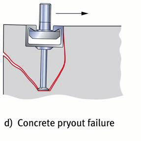
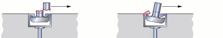
13 CHARACTERISTIC ANCHOR CHANNEL RESISTANCES 4 CHARACTERISTIC ANCHOR CHANNEL RESISTANCES 4.1 Tensile load General The failure types arising under tensile load are shown in figure 4.1. The necessary verification for all failure types is listed in table 4.1. For applications without supplementary reinforcement, the verification is to be provided according to table 4.1, lines 1 to 9. For applications with supplementary reinforcement, the load-bearing capacity must be provided according to table 4.1, lines 1 to 6 and lines 8 to 11. The proof for concrete cone failure is thus replaced by the proof for failure of the supplementary reinforcement. It is assumed at the same time that the anchor load is only taken up by the supplementary reinforcement. 11
14 CHARACTERISTIC ANCHOR CHANNEL RESISTANCES Figure 4.1: Failure types for anchor channels under tensile load 12

 b) c) N M Ed Ed N M Rd,s,l Rd,s,flex N = γ Rk,s,l Ms,l M = γ Rk,s,flex Ms,flex N")
 N = γ Rd,sp Mc NRk,sp c) N = γ Rd,cb Mc N N = Rk,cb c) γ N Mc Rk,re NRd,re = b) γms, re NRk,a b) N = γ not required for anchors")

15 CHARACTERISTIC ANCHOR CHANNEL RESISTANCES 1 Failure types Channel Most unfavourable anchor or screw a NRk,s,a NEd NRd,s,a = Anchor γ b) Ms, a Steel failure Pull-out Connection between anchor and channel Local flexure of the lip Hook head or hammerhead screw Concrete cone failure Splitting Blow-out failure a) Bending of the channel Steel failure in supplementary reinforcement 11 Failure of the supplementary reinforcement in the failure cone a) b) c) N M Ed Ed N M Rd,s,l Rd,s,flex N = γ Rk,s,l Ms,l M = γ Rk,s,flex Ms,flex N b) N N N N N N N a Ed N Rd,s,c N = γ N Rk,s,c Ms, c Rk,s,s Ed NRd,s,s = b) γms a Ed a Ed a Ed a Ed a Ed a Ed NRk,p b) N = γ Rd,p Rd,c Mc NRk,c c) N = γ Rd,sp Mc NRk,sp c) N = γ Rd,cb Mc N N = Rk,cb c) γ N Mc Rk,re NRd,re = b) γms, re NRk,a b) N = γ not required for anchors with edge distance c > 0.5hef most loaded anchor or special screw the load on the anchor in conjunction with the edge distance and spacing should be considered in determining the most unfavourable anchor Rd,a Mc Table 4.1 Required verification for anchor channels under tensile load 13
16 CHARACTERISTIC ANCHOR CHANNEL RESISTANCES Arrangement of a supplementary reinforcement a If the load applied to an anchor N Ed,i is greater than the design value of the resistance for concrete cone failure N Rd,c, the anchor tensile force can be taken up by a supplementary reinforcement. A supplementary reinforcement may only be considered effective if the following requirements are fulfilled (compare figure 4.2): a) The supplementary reinforcement of all anchors must consist of stirrups or loops, have the same diameter, be constructed from ribbed reinforcement steel (f yk 500 N/mm 2 ) with diameter ds 16 mm and adhere to the bending roll diameter according to [7] (EN ). b) The supplementary reinforcement should be arranged as near to the anchor as possible. It should enclose the surface reinforcement as far as possible. Only reinforcement rods with a spacing 0.75 h ef from the anchor may be viewed as effective. c) The minimum anchoring length in the assumed failure cone is min l 1 = 4 d s (with hooks or angle hooks) or min l 1 = 10 d s (straight rods or without welded cross rods). d) The anchoring of the supplementary reinforcement outside of the concrete failure cone must be undertaken with anchoring length l bd according to [7]. e) The splitting forces from the effect of the framework must be taken up by a surface reinforcement that limits the crack widths to the permitted value (w k 0.3 mm). 1 = Supplementary reinforcement 2 = Surface reinforcement Figure 4.2: Anchor channels with supplementary reinforcement from stirrups at the component edge 14
17 CHARACTERISTIC ANCHOR CHANNEL RESISTANCES With anchor channels parallel to the component edge or in a narrow component, the suspension stirrup should be arranged on the longitudinal axis of the channels (compare figure 4.2) Steel failure of anchors, anchor channels or hook head or hammerhead screws The characteristic resistances N Rk,s,a (anchor fracture), N Rk;s,c (failure of the connection between channel and anchor), N Rk,s,l (local flexure of the channel lip), N Rk,s,s (screw failure) and M Rk,s,flex (failure due to bending failure of the channel) are shown in the ETA Pull-out The characteristic resistance for pull-out is given in the respective ETA. It is limited by the concrete pressure under the anchor head. NRk,p = 6 Ah fck,cube ψ ucr,n (4.1) with A h = load application surface of the anchor head = π ( d 2 2 h d ) for round anchor heads 4 f ck,cube = nominal value of the concrete compression strength (cube with an edge length of 150 mm) ψ ucr,n = 1.0 cracked concrete = 1.4 uncracked concrete Concrete cone failure The characteristic resistance of an anchor in cracked concrete for concrete cone failure is taken from the equation (4.2). For attachments in uncracked concrete, the characteristic resistance may be multiplied by the factor ψ ucr,n = N Rk,c = NRk,c α s,n α e,n α c,n ψ re,n ψ ucr,n [N] (4.2) with (4.3) 0 1,5 N Rk,c = 8,5 α f h [N] ch ck,cube ef 15
18 CHARACTERISTIC ANCHOR CHANNEL RESISTANCES f ck,cube = nominal value of the concrete compression strength (cube with an edge length of 150 mm) [N/mm 2 ] α ch = Factor for taking account of the influence of the channel on the concrete failure cone load h ef 0,15 = 1,0 180 (4.4) α s,n = influence of the neighbouring anchor on the concrete cone failure load 1 = 1,5 n si N (4.5) i 1+ 1 i= 1 s cr,n N 0 with s i = distance of the anchor in question to the neighbouring anchor s cr,n (4.6) s cr,n = hef 2 2,8 1, 3 hef hef N Sd,i = design value of the tensile force of anchor i N Sd,0 = design value of the tensile force of the anchor in question n = number of anchors within a distance s cr,n, which influences the concrete cone failure of anchor 0 Figure 4.3: Examples for an anchor channel with different tensile forces on the individual anchors 16
19 CHARACTERISTIC ANCHOR CHANNEL RESISTANCES α e,n = factor for taking account of the influence of a component edge (c 1 < c cr,n ) 0,5 = c1 c cr,n 1 c 1 = edge distance of anchor 1 (see figure 4.4) c cr,n = characteristic edge distance = hef 0,5 scr,n = 2,8 1, 3 hef 180 1,5 hef (4.7) (4.8) Figure 4.4: Anchor channel at an edge (a)) or in a narrow concrete element (b)) α c,n = factor for taking account of the influence of a corner (c 2 < c cr,n ) = c c 2 cr,n 0,5 1 c 2 = distance of the anchor in question to the corner (see figure 4.5) (4.9) 17
20 CHARACTERISTIC ANCHOR CHANNEL RESISTANCES Figure 4.5: Anchor channel influenced by one or two corners a) anchor 1 is calculated c) anchor 2 is calculated b) anchor 2 is calculated d) anchor 1 is calculated Factor ψ re,n takes account of the influence of dense reinforcement for anchoring depths h ef < 100 mm: h 200 ef ψ re,n = 0,5 + 1 (4.10) with h ef in mm. Factor ψ re,n may taken as to ψ re,n = 1.0 following cases. the reinforcement (independent of diameter) is arranged with a spacing 150 mm; or the reinforcement with diameter d s 10 mm is arranged with a spacing 100 mm. ψ ucr,n = factor for taking account of the position of the anchor channel in cracked or uncracked concrete 18
, the factor α c,n for the two corners must be calculated and the product used")
 and two component corners (c 2 < c cr,n ) for the anchor in question")
 is applied in equation (4.2 a) and in the equations for determining α s,n, α e,n and α c,n.")
21 CHARACTERISTIC ANCHOR CHANNEL RESISTANCES ψ ucr,n = 1.0 with the anchor channel positioned in cracked concrete (4.11) = 1.4 with the anchor channel positioned in uncracked concrete Where an anchor is influenced by two corners (c 2,i < c cr,n ), the factor α c,n for the two corners must be calculated and the product used in equation (4.2). For applications with anchor channels with anchoring depth h ef 180 mm with an influence from a component edge (c 1 < c cr,n ) and two component corners (c 2 < c cr,n ) for the anchor in question (for example, see figure 4.5 c)) with an edge distance c < c cr,n, the measurement according to equation (4.2) gives results that are on the safe side. ' Exact results are obtained if for the anchoring depth h ef the value h ef according to equation (4.12) is applied in equation (4.2 a) and in the equations for determining α s,n, α e,n and α c,n. h c = max h ; s h ' max max ef ef ef ccr,n scr,n 180 mm (4.12) with c max = maximum edge distance of the anchor channel to a component edge or to a component corner c cr,n = 0.5 s cr,n according to equation (4.6) s max = largest spacing of the anchor measured from the middle of the anchor s cr,n according to equation (4.6) This verification is not required for the channels dealt with here from DKG and Halfen, as currently only channels with h ef 179 mm are supplied Splitting of the concrete Splitting of the concrete during installation Splitting failure during the installation of the hook head or hammerhead screws is avoided by adhering to the minimum edge distances and spacing and the minimum component thicknesses including the requirements of the edge reinforcement. The minimum measurements and the requirements for the edge reinforcement are given in the ETA (compare [11], [12]). 19
22 CHARACTERISTIC ANCHOR CHANNEL RESISTANCES Splitting of the concrete due to the effect of loads No verification for splitting failure is not required if this is stated in the respective ETA (compare [11], [12]) or if at least one of the following conditions are fulfilled: a) The edge distance in all directions is c 1.0c cr,sp for anchor channels with one anchor, and for anchor channels with 2 anchors, c 1.2c cr,sp. The characteristic edge distance c cr,sp applies to the minimum component thickness. It is shown in the respective approval. b) The characteristic resistance for concrete cone, blow-out and pull-out failure is determined on the assumption of cracked concrete and a reinforcement is present that takes up the splitting forces and limits the crack width to w k 0.3 mm. If proof for splitting failure is required and if not both of the above conditions a) and b) are fulfilled, the characteristic resistance of an anchor channel anchor must be determined using equation (4.13). N = N α α α ψ ψ ψ [N] (4.13) 0 Rk,sp Rk,c s,n e,n c,n re,n ucr,n h,sp with 0 NRk,p NRk,c = min N 0 Rk,c N Rk,p according to equation (4.1) 0 NRk,c α s,n, α e,n, α c,n, ψ re,n, ψ ucr,n according to section However, the values c cr,n and s cr,n are replaced by the values c cr,sp and s cr,sp. These values apply to member thickness h min and are given in the respective approval. The factor ψ h,sp takes account of the influence of the component thickness h actually present on the resistance concerning the splitting failure type. 20
23 CHARACTERISTIC ANCHOR CHANNEL RESISTANCES ψ h,sp = factor for taking account of the member thickness present on the splitting failure load 2/3 2/3 h 2h ef hmin hmin = [-] (4.14) with h min = minimum component thickness according to approval For anchor channels with various distances to member edges (e.g. in the corner or in narrow components), the smallest value for the edge distance c must be used in equation (4.14). If the edge distance between anchor channel and member edge is smaller than the value c cr,sp, a longitudinal reinforcement should be provided along the edge of the component Blow-out failure Proof concerning failure from blow-out failure only needs to be provided if the edge distance between anchor channel and member edge c 0.5h ef. For anchor channels from DKG and Halfen, the minimum edge distances have been determined such that the proof of blow-out failure is not required (compare [11], [12]). If verification for blow-out failure is required, the characteristic resistance of an anchor in cracked concrete is determined using equation (4.15). For anchor channels arranged vertically to the member edge and uniformly loaded, proof is only required for the anchor closest to the edge. N = N α ψ α α ψ [N] (4.15) 0 Rk,cb Rk,cb s,nb g,nb c,nb h,nb ucr,n with 0 N Rk,cb = characteristic resistance of an individual anchor closest to the edge with a large distance to the neighbouring anchor in cracked concrete = 8 c 1 A h fck, cube [N] (4.16) A h = load bearing area of the anchor [mm²] π 2 2 = ( d h d ) in case of a round anchor head [mm²] (4.17) 4 c 1 = edge distance of the anchor channel [mm] 21
24 CHARACTERISTIC ANCHOR CHANNEL RESISTANCES α s,nb = factor for taking account of the influence of the neighbouring anchor. It is determined using equation (4.5), but the value s cr,nb is used for the characteristic spacing instead of s cr,n. s cr,nb = characteristic spacing for blow-out failure = 4 c 1 (4.18) α c,nb = factor for taking account of the influence of a corner 0,5 c = 2 1 [-] c (4.19) cr,nb c 2 = distance of the anchor in question to the corner (see figure 4.5) c cr,nb = 0.5 s cr,nb (4.20) If an anchor is influenced by 2 corners (c 2 < c cr,n ), the factor α c,nb must be determined for both edge distances c 2,1 and c 2,2 and the product of the factors α c,nb used in equation (4.15). ψ g,nb = factor for taking account of the influence of the load application surface of the neighbouring anchor = n + ( 1 s1 n ) 1 4 c1 for s 1 4c 1 (4.21) n = number of anchors under tensile load parallel to the edge α h,nb = factor for taking account of the member thickness if the distance of the head to the upper or lower edge is < 2 c 1 (see figure 4.6) = hef + f 2c1 + f (4.22) 1 [-] 4c1 4c1 f = distance between the upper side of the anchor head (position of the load application) and the lower side of the member (see figure 4.6) ψ ucr,n = see equation (4.11) 22

25 CHARACTERISTIC ANCHOR CHANNEL RESISTANCES Figure 4.6: Anchor channel in the corner of a thin component Steel failure in supplementary reinforcement The characteristic resistance of the supplementary reinforcement N Rk,s,re of an anchor is N Rk,re = n A s f yk [N] (4.23) with n = number of legs of the supplementary reinforcement for an anchor in the failure cone A s = Cross-section of a leg of the supplementary reinforcement f yk = nominal value of the yield point of the supplementary reinforcement 500 N/mm Anchorage failure of the supplementary reinforcement in the failure cone The characteristic resistance of the supplementary reinforcement for failure due to anchorage failure is calculated according to equation (4.24). N Rd,a l π d f = α n 1 s bd (4.24) 23
26 CHARACTERISTIC ANCHOR CHANNEL RESISTANCES with n = number of legs of the additional reinforcement effective for an anchor l 1 = Anchoring length of the supplementary reinforcement in the failure cone l b,min (see figure 4.2) l b,min = minimum anchoring length = 4d s (hooks or angle hooks) = 10 d s anchoring with straight rods with or without welded cross rods d s = Diameter of the supplementary reinforcement f bd = Design value of the bond strength in accordance with EN = f bk / γ c f bk = characteristic value of the bond strength in accordance with EN [7] taking account of the concrete cover of the supplementary reinforcement α = influencing factor in accordance with EN = 0.7 for reinforcement rods with hooks 4.2 Shear load General In this section, only shear loads acting vertically to the rail axis are taken into account. The failure types arising under shear load are shown in figure 4.7. The necessary verification concerning shear loads is listed in table 4.2. For applications without supplementary reinforcement, the verification is to be provided according to table 4.2, lines 1 to 5. For applications with supplementary reinforcement, the load-bearing capacity must be verified in accordance with table 4.2, lines 1 to 4 and 6 to 7, i.e. as with tensile loads, the proof concerning concrete edge failure is replaced by the proof concerning failure of the supplementary reinforcement. It is assumed at the same time that the complete shear load is taken up by the supplementary reinforcement. 24

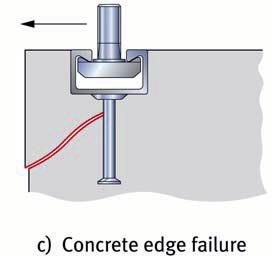
27 CHARACTERISTIC ANCHOR CHANNEL RESISTANCES Figure 4.7: Failure types for anchor channels under shear load 25
28 CHARACTERISTIC ANCHOR CHANNEL RESISTANCES 1 Type of failure Hook head or hammerhead screw 2 Anchor 1) 3 Steel failure Shear load without lever arm Anchors/ Channel 1) Shear load with lever arm Local flexure of the channel lip Hook head or hammerhead screw Concrete cone failure on the side away from the load 7 Concrete edge failure 8 Steel failure of the additional reinforcement 9 a Failure of the additional reinforcement in the cone Channel V Rk,s,l Ed VRd,s,l = γ Ms,l a V Most unfavourable anchor or special screw V V V Rk,s Ed VRd,s,s = γ Ms a V Rk,s,a Ed VRd,s,a = γ Ms a with V Rk,s,a = N Rk,s,a VRk,s,c VEd VRd,s,c = γ a with V Rk,s,c = N Rk,s,c V V Ms Rk,s Ed VRd,s,s = γ Ms a V V N N a Ed a Ed V Rk,cp VRd,cp = γ Mc b V Rk,c VRd,c = γ Mc b N Rk,re Ed,re NRd,re = γ Ms,re a N,,, = Rk a Ed re NRd a γ Mc a Most loaded anchor or special screw b The load applied to the anchor is to be considered when determining the most unfavourable anchor in connection with edge distances and axis spacing 1) The verifications according to line 2 and 3 are not included in CEN/TS, but will be in the future. Table 4.2 Required verification for anchor channels under shear load The most unfavourable anchor is defined in the same way as for tensile load (compare section 4.1.1). 26

 and the same rod diameter is to be used for all anchors.")
![The bending roll diameter is selected in accordance with EN 1992-1-1 [7].](/docs-images/75/71718621/images/29-2.jpg "A supplementary reinforcement is only considered as effective if it fulfils the following requirements (compare figure 4.8).")
 The anchoring length of the supplementary reinforcement in the concrete failure cone must be at least: min l 1 = 10d s straight reinforcement rods with or")
29 CHARACTERISTIC ANCHOR CHANNEL RESISTANCES Design of supplementary reinforcement a If the design load applied to an anchor V Ed,i is greater than the design value of the concrete cone failure, the shear load on the anchor can be taken up by a supplementary reinforcement, which must be designed for the complete shear load. It must be made of ribbed concrete steel (d s 16 mm, f yk 500 N/mm 2 ) and the same rod diameter is to be used for all anchors. The bending roll diameter is selected in accordance with EN [7]. A supplementary reinforcement is only considered as effective if it fulfils the following requirements (compare figure 4.8). a) The distance of the reinforcement rods from the anchor must be 0.75 c 1. b) The anchoring length of the supplementary reinforcement in the concrete failure cone must be at least: min l 1 = 10d s straight reinforcement rods with or without welded transverse rods = 4d s bent reinforcement rods (hooks or angle hooks) c) Along the edge of the component, there must be a longitudinal reinforcement for taking up the tensile forces arising from the effect of the strut and tie model (figure 4.8). For simplification, the angle of the struts can be assumed as 45. Figure 4.8: Surface reinforcement for transfer of shear loads 27
30 CHARACTERISTIC ANCHOR CHANNEL RESISTANCES Steel failure of hook head and hammerhead screw and local flexure of channel lips Shear load without lever arm The characteristic resistances for steel failure of hook head or hammerhead screw (V Rk,s,s ), steel failure of the anchor (V Rk,s,a ) and for failure as a result of local flexure of the channel lips (V Rk,s,l ) are given in the respective ETA Shear load with lever arm The characteristic resistance of a hook head or hammerhead screw with steel failure is defined according to equation (4.25). V Rk,s αm M = l Rk,s (4.25) with α M = factor for taking account of the degree of restraint of the attachment = 1.0 no restraint, free rotation of the attachment possible, see figure 4.9 a = 2.0 completely fixed, no rotation of the attachment possible, see figure 4.9 b l = lever arm (see figure 4.9) M RK,s = characteristic resistance of the hook head or hammerhead screw for bending failure = 0 N Ed M Rk,s 1 NRd, s [Nm] (4.26) 0 M Rk,s = Base value for the characteristic bending resistance of the hook N Rd,s = head or hammerhead screw N γ Rk,x Ms N Rk,s = characteristic resistance of the screw with tensile load γ M,s = material safety factor (4.27) The values M 0 Rk,s, N Rk,s and γ M,s are given in the approval. 28

. VRk,cp = k5 NRk,c [Nm] (4.28) with k 5 = factor given in the respective approval. As a rule, it is = 1.")
31 CHARACTERISTIC ANCHOR CHANNEL RESISTANCES If it is assumed that the attachment cannot rotate, the moment M Ed = V Ed l / 2 must be taken up by the attachment and transferred. If the shear load is applied with lever arm, the characteristic resistance of the hook head or hammerhead screw is generally smaller than the value for the failure type local flexure of channel lips. Therefore, this verification is not required. Figure 4.9: Anchor channel for which the shear load is applied with lever arm a) freely rotatable attachment b) non-rotatable attachment Concrete pry-out failure The characteristic resistance arises from the equation (4.28). VRk,cp = k5 NRk,c [Nm] (4.28) with k 5 = factor given in the respective approval. As a rule, it is = 1.0 for h ef < 60 mm = 2.0 for hef 60 mm For anchor channels with supplementary reinforcement for taking up shear loads, the factor k 5 in equation (4.28) should be multiplied with the factor N Rk,c = characteristic resistance of the anchor under tensile load for the failure mode concrete cone failure according to section The most unfavourable anchor with an applied shear load must be verified. 29
32 CHARACTERISTIC ANCHOR CHANNEL RESISTANCES Concrete edge failure Verification for concrete edge failure is not necessary if the edge distance in all directions is c 10h ef and c 60d. The lower value is decisive. The characteristic resistance of an anchor in cracked concrete is taken from the equation (4.29). V = V α α α α ψ [N] (4.29) Rk,c 0 Rk,c s,v c,v h,v 90,V re,v with V 0 Rk,c = α f c [N] (4.30) p ck,cube 1,5 1 with α p = product factor [N 0.5 /mm]. It is shown in the respective approval. = 2.5 (guide value) f ck,cube = nominal value of the concrete compressive strength (cubes with 150 mm side length) The influence of neighbouring anchors on the concrete cone failure is taken account of with the factor α s,v in accordance with (4.37) 1 α s,v = 1,5 n s i V i 1 1 (4.31) + i= 1 s cr,v V 0 with (see figure 4.10) s i = distance between the anchor under consideration and the neighbouring anchors s cr,v scr,v = 4 c1 + 2 bch (4.32) b ch = width of the anchor channel V i = shear load of an influencing anchor V 0 = shear load of the anchor in question n = number of anchors within a distance of s cr,v on both sides of the anchor under consideration 30

 with c = 0,5 s = 2 c + b (4.")
 the factor α c,v in accordance with equation (4.")
33 CHARACTERISTIC ANCHOR CHANNEL RESISTANCES Figure 4.10: Example for an anchor channel with differing shear forces applied to the anchors The influence of a member corner is taken account of with factor α c,v 0,5 c2 α c,v = c cr,v 1 (4.33) with c = 0,5 s = 2 c + b (4.34) cr,v cr,v 1 ch If the anchor is influenced by two corners (see figure 4.11) the factor α c,v in accordance with equation (4.33) must be calculated for each corner and the product used in equation (4.29). 31
34 CHARACTERISTIC ANCHOR CHANNEL RESISTANCES Figure 4.11: Example of an anchor channel with anchors influenced by a) one or b) two corners. Anchor 2 is the anchor in question. The influence of a component thickness h < h cr,v is taken account of with factor α h,v 2 3 h α h,v = 1 h cr,v (4.35) with h = 2 c + 2 h (see figure 4.12) (4.36) cr,v 1 ch h ch = height of the channel Figure 4.12: Example of an anchor channel influenced by the member thickness 32
 α 90,V = 2,5 (4.37) Figure 4.")
 and the type of reinforcement present at the edge. ψ re,v = 1.")
 and height of the anchor channel h ch 40")


35 CHARACTERISTIC ANCHOR CHANNEL RESISTANCES The factor α 90,V takes account of the influence of shear loads that are applied parallel to the edge (see figure 4.13) α 90,V = 2,5 (4.37) Figure 4.13: Anchor channel under load parallel to the component edge The factor ψ re,v takes account of the state of the concrete (cracked or uncracked) and the type of reinforcement present at the edge. ψ re,v = 1.0 anchor channel in cracked concrete without edge reinforcement or stirrups = 1.2 anchor channel in cracked concrete with straight edge reinforcement ( Ø 12 mm) and height of the anchor channel h ch 40 mm = 1.4 anchor channel in cracked concrete with edge reinforcement and stirrups with small axis spacing or small-meshed reinforcement (a 100 mm and a 2 c 1 ) or anchor channels in uncracked concrete With anchor channels in a narrow, thin component (see figure 4.14) with c 2,max c cr,v (c cr,v = 2 c 1 +b ch ) and h < h cr,v (h cr,v = 2 c 1 +2 h ch ) a determination of the characteristic resistance with equation (4.29) leads to results that are on the safe side. More exact results can be achieved by limiting the edge distance c 1 in equation (4.29) with the value c 1 in accordance with equation (4.38). 33
36 CHARACTERISTIC ANCHOR CHANNEL RESISTANCES ' c1 = max 0,5 (c2,max b ch ) ; 0,5 (h 2h ch ) [mm] (4.38) with c 2,max = largest edge distance c 2,1 and c 2,2 parallel to the direction of the load The value c 1 is used in the equations (4.30), (4.32), (4.34) and (4.36). Figure 4.14: Example of an anchor channel where the concrete breaking load is influenced by two edges parallel to the shear load and by the component thickness Steel failure in supplementary reinforcement The determination of the characteristic resistance of the supplementary reinforcement during steel failure is carried out with the equation (4.23) Bond failure of the supplementary reinforcement in the failure cone The characteristic resistance of the supplementary reinforcement for failure due to anchorage failure from the failure section arises from the equation (4.24). With a supplementary reinforcement out of welded reinforcing steel mesh with welded cross bars in the failure section, the factor as with hooks is α = 0.7. With a supplementary reinforcement of straight rods, α = 1.0 may be assumed. 34
 to design the supplementary")


 in accordance with Schmid ([15]).")
37 CHARACTERISTIC ANCHOR CHANNEL RESISTANCES Alternative possibility in accordance with ETA ([11], [12]) to design the supplementary reinforcement The verification for the shear load with additional reinforcement can be carried out in accordance with [11] and [12] either according to sections and or according to the following explanations. The approaches according to sections an are conservative and provide results that lie clearly on the safe side. Results nearer to reality can be achieved with the model already in use for channels from DKG and Halfen in the ETA ([11], [12]) in accordance with Schmid ([15]). The calculation of the characteristic resistance of the supplementary reinforcement is as follows. 35
38 CHARACTERISTIC ANCHOR CHANNEL RESISTANCES Figure 4.15: Verification of anchor channels for shear loads with reinforcement (direction of load vertically to the component edge), in accordance with [11], [12] VEd VRd,re = V Rk,re / γ M a ( ) V = max V ;V Ed Ed Ed V = V / x Rk,re Rk,c,re (4.39) (4.40) (4.41) with V = V + V V A f (4.42) Rk,c,re Rk,c,hook Rk,c,bond Rk,c,re,max s y,k m+ n m 0,1 n 0,1 fck fck VRk,c,hook = ψ1 ψ3 ψ4 As fy,k + ψ2 ψ3 ψ4 As fy,k j= 1 30 (4.43) j= 1 30 m+ n (4.44) V = π d l f ( ) Rk,c,bond s j bk j= 1 V = 4,2 c V (4.45) V -0,12 Rk,c,re,max 1 Rk,c = V α α α (4.46) 0 Rk,c Rk,c s,v c,v h,v 36
 (4.")
 ( d / d ) 2/3 ψ = (see figure 4.15) (4.")
![49) 3 s,l s 0,4 0,25 lj 10 ψ 4 = c1 ds d s = stirrup diameter [mm] d s,l = rod diameter of the edge reinforcement [mm] l 4 = anchoring length of a stirrup in the failure cone [mm] = c1 cc 0,7 ( ej](/docs-images/75/71718621/images/39-2.jpg "bch ) c = 1 c [mm] for stirrups crossed by the assumed crack c (4.")
39 CHARACTERISTIC ANCHOR CHANNEL RESISTANCES s 150mm 50mm a ( c1 cc + 0,7b ch 4d s ) / 0, 35 c1 cc 6mm ds 20mm ψ 1 = Effectiveness factor = 0.67 for stirrups directly next to the shear load 1 for a stirrup under a shear load 3 (4.47) (4.48) for a stirrup between 2 shear loads applied to an anchor channel (spacing of the loads s cr,v in accordance with equation (4.32) 2 ψ 2 = Effectiveness factor = 0.11 for further stirrups in the failure cone 4 (for designations see figure 4.16 and figure 4.17) ( d / d ) 2/3 ψ = (see figure 4.15) (4.49) 3 s,l s 0,4 0,25 lj 10 ψ 4 = c1 ds d s = stirrup diameter [mm] d s,l = rod diameter of the edge reinforcement [mm] l 4 = anchoring length of a stirrup in the failure cone [mm] = c1 cc 0,7 ( ej bch ) c = 1 c [mm] for stirrups crossed by the assumed crack c (4.50) [mm] for stirrups directly under the load or for stirrups crossed at right angles by the assumed crack 4 d s c 1 = Edge distance [mm] c c = Concrete cover [mm] e j = distance of the stirrup from the loading point [mm] b ch = profile width [mm] (according to table 2) A s = cross section of a stirrup leg [mm 2 ] ƒ y,k = characteristic yield point of the reinforcement [N/mm 2 ] ƒ ck = characteristic concrete pressure resistance (determined on cubes with an edge length of 150 mm) [N/mm 2 ] ƒ bk = characteristic bond strength [N/mm 2 ) m = number of stirrups in the assumed failure cone with ψ 1 37
40 CHARACTERISTIC ANCHOR CHANNEL RESISTANCES n = number of stirrups in the assumed failure cone with ψ 2 α = stirrup spacing x = e s / z 1 + [ ] (4.51) Factor to take account of the excentricity between reinforcement and the load applied e s = distance between reinforcement and the shear force applied to the channel z = 0.85d [mm] Inner lever arm of the component d = min( 2h ef,2c 1) 0 V Rk,c = according to equation (4.30) a V Ed = design value of the load applied to an anchor of an anchor channel, see [5], Section Figure 4.16: Effectiveness factors ψ 1 and ψ 2 for one load Figure 4.17: Effectiveness factors ψ 1 and ψ 2 for two loads 4.3 Combined tensile and shear load Anchor channels without supplementary reinforcement Steel failure decisive under tensile and shear load With combined tensile and shear load on anchor channels without supplementary reinforcement, and steel failure in both directions, the interaction equation (4.52) must be fulfilled. In each case the largest value β N and β V for the individual failure types is to be used. 38
 or (4.54) must be fulfilled. ß + ß 1,2 (4.53) N V ß + ß 1 1,5 1,5 N V (4.54) with ßN = N Ed / NRd 1 ßV = V Ed / VRd 1 4.3.2 Anchor channels with supplementary reinforcement With anchor channels with a supplementary reinforcement for taking up the tensile and shear loads, section 4.")
41 CHARACTERISTIC ANCHOR CHANNEL RESISTANCES ß + ß N V (4.52) with ßN = N Ed / NRd 1 ßV = V Ed / VRd Other failure types decisive In cases of different failure types under tensile and shear load, one of the following equations (4.53) or (4.54) must be fulfilled. ß + ß 1,2 (4.53) N V ß + ß 1 1,5 1,5 N V (4.54) with ßN = N Ed / NRd 1 ßV = V Ed / VRd Anchor channels with supplementary reinforcement With anchor channels with a supplementary reinforcement for taking up the tensile and shear loads, section applies. For anchor channels on the component edge with a supplementary reinforcement for taking up shear loads, equation (4.55) (linear interaction) applies. The largest value β N and β V for the individual failure types is to be used. β N + βv 1,0 (4.55) 39
42 CHARACTERISTIC ANCHOR CHANNEL RESISTANCES Figure 4.18: Interaction diagram for combined tensile and shear load New approach for anchor channels without supplementary reinforcement in accordance with fib Design Guide [16] The equations (4.52), (4.53) and (4.54) generally provide very conservative results as they link differing failure types and the resulting stresses, which in addition appear at different points. More precise results are achieved if equations (4.52) (steel failure) and (4.54) (concrete failure) are taken into account separately. Figure 4.19 illustrates the procedure. The grey area in figure 4.19 shows the difference to the approach according to equation (4.54). 40
43 CHARACTERISTIC ANCHOR CHANNEL RESISTANCES Figure 4.19: Comparison of the interaction equations (4.52) and (4.53) with (4.54) 41
44 DESIGN EXAMPLES 5 DESIGN EXAMPLES 5.1 Characteristic values from approval dimension [mm] HTA 28/15 HTA 38/17 HTA 40/22 HTA 50/30 Anchor channels HTA 52/34 HTA 55/42 HTA 72/48 HTA 40/25 HTA 49/30 HTA 54/33 HTA 72/49 b ch 28,00 38,00 39,50 49,00 52,50 54,50 72,00 40,00 50,00 53,50 72,00 h ch 15,25 17,50 23,00 30,00 33,50 42,00 48,50 25,00 30,00 33,00 49,00 Characteristic resistances - screws M6 M8 M10 M12 M16 M20 M24 M27 M30 γ Ms N Rk,s [kn] 8,0 14,6 23,2 33,7 62,8 98,0 141,2 183,6 224,4 2, V Rk,s [kn] 4,8 8,8 13,9 20,2 37,6 58,8 84,7 110,2 134,6 1,67 M 0 Rk,s [Nm] 6,3 15,0 29,9 52,4 133,2 259,6 449,0 665,8 899,6 1,67 N Rk,s [kn] 16,1 29,3 46,4 67,4 125,6 196,0 282,4 367,2 448,8 1, V Rk,s [kn] 8,0 14,6 23,2 33,7 62,8 98,0 141,2 183,6 224,4 1,25 M 0 Rk,s [Nm] 12,2 30,0 59,8 104,8 266,4 519,3 898,0 1331,5 1799,2 1,25 N Rk,s [kn] 10,1 18,3 29,0 42,2 78,5 122,5 176,5 229,5 280,5 2,86 A4 V -50 Rk,s [kn] 6,0 11,0 17,4 25,3 47,1 73,5 105,9 137,7 168,3 2,38 M 0 Rk,s [Nm] 7,6 18,7 37,4 65,5 166,5 324,5 561,3 832,2 1124,5 2,38 N Rk,s [kn] 14,1 25,6 40,6 59,0 109,9 171,5 247,1 321,3 392,7 1,87 A4 V -70 Rk,s [kn] 8,4 15,4 24,4 35,4 65,9 102,9 148,3 192,8 235,6 1,56 M 0 Rk,s [Nm] 10,7 26,2 52,3 91,7 233,1 454,4 785,8 1165,1 1574,3 1,56 42
45 DESIGN EXAMPLES profile screws Hot-rolled profiles HTA HTA 40/22 50/30 M10 M10 - M16 - M20 HTA 52/34 M10 - M20 HTA 55/42 M10 - M24 HTA 72/48 M20 - M30 I y normal steel [mm 4 ] I y stainless steel [mm 4 ] N Rk,s,c [kn] γ Ms,ca 1,8 s slb [mm] N Rk,s,l [kn] γ Ms,l 1,8 V Rk,s,c [kn] γ Ms,ca 1,8 V Rk,s,l [kn] 26 40,3 71, γ Ms,l 1,8 M Rk,s,flex normal steel [Nm] M Rk,s,flex stainless steel [Nm] γ Ms,flex 1,15 N Rk,p in C12/15 [kn] 13,5 21,1 33,9 37,2 46,4 ψ c (f ck,cube /15) γ Mp 1,5 α ch 0,88 0,91 0,98 1,00 1,00 h ef [mm] γ Mc 1,5 k 5 2,0 α p ψ re,v 3,0 3,5 3,5 3,5 4,0 Cracked concrete, 3,5 4,1 4,1 4,1 4,7 straight rebars stirrups 4,0 4,7 4,7 4,7 5,3 α h,v (h/h cr,v ) 2/3 43
46 DESIGN EXAMPLES Profiles Screws HTA 28/15 M6 M12 Cold-formed profiles HTA HTA 38/17 40/25 M10 M10 - M16 - M16 HTA 49/30 M10 - M20 HTA 54/33 M10 - M20 HTA 72/49 M20 - M30 I y normal steel [mm 4 ] I y stainless [mm 4 ] steel N Rk,s,c [kn] γ Ms,ca 1,8 s slb [mm] N Rk,s,l [kn] γ Ms,l 1,8 V Rk,s,c [kn] γ Ms,ca 1,8 V Rk,s,l [kn] γ Ms,l 1,8 M Rk,s,flex [Nm] normal steel M Rk,s,flex stainless steel [Nm] γ Ms,flex 1,15 N Rk,p in [kn] 7,6 13,5 13,5 21,1 37,2 46,4 C12/15 ψ c (f ck,cube /15) γ Mp 1,5 α ch 0,81 0,88 0,88 0,91 0,98 1,00 h ef [mm] γ Mc 1,5 k 5 2,0 α p ψ re,v 2,5 3,0 3,0 3,5 3,5 4,0 Cracked 3,0 3,5 3,5 4,1 4,1 4,7 concrete, straight rebars stirrups 3,5 4,0 4,0 4,7 4,7 5,3 α h,v (h/h cr,v ) 2/3 44
![DESIGN EXAMPLES dimension [mm] JTA K 28/15 JTA K 38/17 JTA W 40/22 JTA W 50/30 Anchor channel JTA W 53/34 JTA W 55/42 JTA W 72/48 JTA K 40/25 JTA K 50/30 JTA K 53/34 JTA K 72/48 b ch 28,00 38,00](/docs-images/75/71718621/images/47-0.jpg "39,50 49,00 52,50 54,50 72,00 40,00 50,00 53,50 72,00 h ch 15,25 17,50 23,00 30,00 33,50 42,00 48,50 25,00 30,00 33,00 49,00 Characteristic resistances - screws M6 M8 M10 M12 M16 M20 M24 M27 M30 γ Ms")
![N Rk,s [kn] 8,0 14,6 23,2 33,7 62,8 98,0 141,2 183,6 224,4 2,00 4.](/docs-images/75/71718621/images/47-1.jpg "6 V Rk,s [kn] 4,8 8,8 13,9 20,2 37,7 58,8 84,7 110,2 134,6 1,67 M 0 Rk,s [Nm] 6,3 15,0 29,9 52,4 133,2 259,6 449,0 665,8 899,6 1,67 N Rk,s [kn] 16,1 29,3 46,4 67,4 125,6 196,0 282,4 367,2 448,8 1,50")
![8.8 V Rk,s [kn] 8,0 14,6 23,2 33,7 62,8 98,0 141,2 183,6 224,4 1,25 M 0 Rk,s [Nm] 12,2 30,0 59,8 104,8 266,4 519,3 898,0 1331,5 1799,2 1,25 N Rk,s [kn] 10,1 18,3 29,0 42,2 78,5 122,5 176,5 229,5](/docs-images/75/71718621/images/47-2.jpg "280,5 2,86 A4 V Rk,s [kn] 6,0 11,0 17,4 25,3 47,1 73,5 105,9 137,7 168,3 2,38-50 M 0 Rk,s [Nm] 7,6 18,7 37,4 65,5 166,5 324,5 561,3 832,2 1124,5 2,38 N Rk,s [kn] 14,1 25,6 40,6 59,0 109,9 171,5 247,1")
47 DESIGN EXAMPLES dimension [mm] JTA K 28/15 JTA K 38/17 JTA W 40/22 JTA W 50/30 Anchor channel JTA W 53/34 JTA W 55/42 JTA W 72/48 JTA K 40/25 JTA K 50/30 JTA K 53/34 JTA K 72/48 b ch 28,00 38,00 39,50 49,00 52,50 54,50 72,00 40,00 50,00 53,50 72,00 h ch 15,25 17,50 23,00 30,00 33,50 42,00 48,50 25,00 30,00 33,00 49,00 Characteristic resistances - screws M6 M8 M10 M12 M16 M20 M24 M27 M30 γ Ms N Rk,s [kn] 8,0 14,6 23,2 33,7 62,8 98,0 141,2 183,6 224,4 2, V Rk,s [kn] 4,8 8,8 13,9 20,2 37,7 58,8 84,7 110,2 134,6 1,67 M 0 Rk,s [Nm] 6,3 15,0 29,9 52,4 133,2 259,6 449,0 665,8 899,6 1,67 N Rk,s [kn] 16,1 29,3 46,4 67,4 125,6 196,0 282,4 367,2 448,8 1, V Rk,s [kn] 8,0 14,6 23,2 33,7 62,8 98,0 141,2 183,6 224,4 1,25 M 0 Rk,s [Nm] 12,2 30,0 59,8 104,8 266,4 519,3 898,0 1331,5 1799,2 1,25 N Rk,s [kn] 10,1 18,3 29,0 42,2 78,5 122,5 176,5 229,5 280,5 2,86 A4 V Rk,s [kn] 6,0 11,0 17,4 25,3 47,1 73,5 105,9 137,7 168,3 2,38-50 M 0 Rk,s [Nm] 7,6 18,7 37,4 65,5 166,5 324,5 561,3 832,2 1124,5 2,38 N Rk,s [kn] 14,1 25,6 40,6 59,0 109,9 171,5 247,1 321,3 392,7 1,87 A4 V -70 Rk,s [kn] 8,4 15,4 24,4 35,4 65,9 102,9 148,3 192,8 235,6 1,56 M 0 Rk,s [Nm] 10,7 26,2 52,3 91,7 233,1 454,4 785,8 1165,1 1574,3 1,56 45
48 DESIGN EXAMPLES Profiles screws Hot-rolled profiles JTA JTA W 40/22 W 50/30 M10 M10 - M16 - M20 JTA W 53/34 M10 - M20 JTA W 55/42 M10 - M24 JTA W 72/48 M20 - M30 I y normal steel [mm 4 ] I y stainless steel [mm 4 ] N Rk,s,c [kn] γ Ms,ca 1,8 s slb [mm] N Rk,s,l [kn] γ Ms,l 1,8 V Rk,s,c [kn] γ Ms,ca 1,8 V Rk,s,l [kn] 26 40,3 71, γ Ms,l 1,8 M Rk,s,flex normal steel [Nm] M Rk,s,flex stainless steel [Nm] γ Ms,flex 1,15 N Rk,p in C12/15 [kn] 10,8 15,9 29,7 38,4 50,9 ψ c (f ck,cube /15) γ Mp 1,5 α ch 0,88 0,91 0,98 1,00 1,00 h ef [mm] γ Mc 1,5 k 5 2,0 α p ψ re,v 3,0 3,5 3,5 3,5 4,0 Cracked concrete, 3,5 4,1 4,1 4,1 4,7 straight rebars Stirrups 4,0 4,7 4,7 4,7 5,3 α h,v (h/h cr,v ) 2/3 46
Depending on the application and the anchor type one of the following two concepts can be applied: Partial safety factor concept.
 Anchor design Safety concept Depending on the application and the anchor type one of the following two concepts can be applied: For anchors for use in concrete having an European Technical Approval (ETA)
English Version. Design of fastenings for use in concrete - Part 4-2: Headed Fasteners
 Update Standards. TECHNICAL SPECIFICATION SPÉCIFICATION TECHNIQUE TECHNISCHE SPEZIFIKATION DD CEN/TS 1992-4-2:29 CEN/TS 1992-4-2 May 29 ICS 21.6.1; 91.8.4 English ersion Design of fastenings for use in
Hilti HSV-F Stud anchor
 Product Data Sheet Hilti Anchor version Benefits torque-controlled mechanical expansion allows immediate load application HSV-F Carbon steel, hot dipped galvanised, min 42 microns coating thickness setting
1 Input data. Profis Anchor Company: Specifier: Address: Phone I Fax: Page: Project: Sub-Project I Pos. No.
 1 Specifier's comments: Check of Existing Base plate (B6)- According to max. forces on Node No. 11979, LC 1.4(D.L.+WX) 1 Input data Anchor type and diameter: HIT-HY 200 + HIT-V-F (8.8) M27 Seismic/Filling
Design of fastenings for use in concrete
 DRAFT FOR DEELOPMENT DD CEN/TS 1992-4-2:29 Design of fastenings for use in concrete Part 4-2: Headed Fasteners ICS 21.6.1; 91.8.4 NO COPYING WITHOUT BSI PERMISSION EXCEPT AS PERMITTED BY COPYRIGHT LAW
1 Input data. Profis Anchor Company: Specifier: Address: Phone I Fax: Page: Project: Sub-Project I Pos. No.
 1 Specifier's comments: Design of Typical Baseplate B1 according to Max. forces in Node No. (5984), LC19 (1.2D+1.6S+0.8WY CASE B) 1 Input data Anchor type and diameter: HIT-HY 200 + HIT-V (8.8) M24 Seismic/Filling
Design of fastenings for use in concrete
 DRAFT FOR DEVELOPMENT DD CEN/TS 1992-4-5:29 Design of fastenings for use in concrete Part 4-5: Post-installed fasteners Chemical systems ICS 21.6.99; 91.8.4 NO COPYING WITHOUT BSI PERMISSION EXCEPT AS
Design of AAC wall panel according to EN 12602
 Design of wall panel according to EN 160 Example 3: Wall panel with wind load 1.1 Issue Design of a wall panel at an industrial building Materials with a compressive strength 3,5, density class 500, welded
A through-bolt expansion wedge anchor with controlled torque, for use in cracked and non cracked concrete.
 A through-bolt expansion wedge anchor with controlled torque, for use in cracked and non cracked concrete. ETA assessed option 1 anchor. Galvanised carbon steel, with 316 (A4) stainless steel expansion
DECLARATION OF PERFORMANCE
 EN DECLARATION OF PERFORMANCE DoP No. Hilti HUS3 0672-CPD-0361 1. Unique identification code of the product-type: Hilti Screw Anchor HUS3 2. Type, batch or serial number as required pursuant to Article
Design of reinforced concrete sections according to EN and EN
 Design of reinforced concrete sections according to EN 1992-1-1 and EN 1992-2 Validation Examples Brno, 21.10.2010 IDEA RS s.r.o. South Moravian Innovation Centre, U Vodarny 2a, 616 00 BRNO tel.: +420-511
Detailing. Lecture 9 16 th November Reinforced Concrete Detailing to Eurocode 2
 Detailing Lecture 9 16 th November 2017 Reinforced Concrete Detailing to Eurocode 2 EC2 Section 8 - Detailing of Reinforcement - General Rules Bar spacing, Minimum bend diameter Anchorage of reinforcement
Edward C. Robison, PE, SE. 02 January Architectural Metal Works ATTN: Sean Wentworth th ST Emeryville, CA 94608
 Edward C. Robison, PE, SE ks ATTN: Sean Wentworth 1483 67 th ST Emeryville, CA 94608 02 January 2013 SUBJ: 501 CORTE MADERA AVE, CORTE MADERA, CA 94925 BALCONY GUARD BASE PLATE MOUNTS The guards for the
Department of Mechanics, Materials and Structures English courses Reinforced Concrete Structures Code: BMEEPSTK601. Lecture no. 6: SHEAR AND TORSION
 Budapest University of Technology and Economics Department of Mechanics, Materials and Structures English courses Reinforced Concrete Structures Code: BMEEPSTK601 Lecture no. 6: SHEAR AND TORSION Reinforced
Design of Reinforced Concrete Beam for Shear
 Lecture 06 Design of Reinforced Concrete Beam for Shear By: Prof Dr. Qaisar Ali Civil Engineering Department UET Peshawar drqaisarali@uetpeshawar.edu.pk 1 Topics Addressed Shear Stresses in Rectangular
Structural Calculations for Juliet balconies using BALCONY 2 System (Aerofoil) handrail. Our ref: JULB2NB Date of issue: March 2017
 handrail. Our ref: JULB2NB Date of issue: March 2017") Juliet balconies using BALCONY 2 System (Aerofoil) handrail PAGE 1 (ref: JULB2NB280317) Structural Calculations for Juliet balconies using BALCONY 2 System (Aerofoil) handrail Our ref: JULB2NB280317 Date
Juliet balconies using BALCONY 2 System (Aerofoil) handrail PAGE 1 (ref: JULB2NB280317) Structural Calculations for Juliet balconies using BALCONY 2 System (Aerofoil) handrail Our ref: JULB2NB280317 Date
Annex - R C Design Formulae and Data
 The design formulae and data provided in this Annex are for education, training and assessment purposes only. They are based on the Hong Kong Code of Practice for Structural Use of Concrete 2013 (HKCP-2013).
2D - STRIP ANCHOR LIFTING SYSTEM
 2D - STRIP ANCHOR LIFTING SYSTEM WWW.TERWA.COM Terwa reserves the right to make changes to the documentation at any time Page 1 OVERVIEW LIFTING CLUTCHES AND TRANSPORT ANCHOR SA-B SA-ST SA-TTU UNIVERSAL
Design of Reinforced Concrete Beam for Shear
 Lecture 06 Design of Reinforced Concrete Beam for Shear By: Civil Engineering Department UET Peshawar drqaisarali@uetpeshawar.edu.pk Topics Addressed Shear Stresses in Rectangular Beams Diagonal Tension
Bending and Shear in Beams
 Bending and Shear in Beams Lecture 3 5 th October 017 Contents Lecture 3 What reinforcement is needed to resist M Ed? Bending/ Flexure Section analysis, singly and doubly reinforced Tension reinforcement,
Module 6. Shear, Bond, Anchorage, Development Length and Torsion. Version 2 CE IIT, Kharagpur
 Module 6 Shear, Bond, Anchorage, Development Length and Torsion Lesson 15 Bond, Anchorage, Development Length and Splicing Instruction Objectives: At the end of this lesson, the student should be able
1 Input data. 2 Overall Result. 3 Geometry. PROFIS Anchor Channel Company: Specifier: Address: Phone Fax:
 Phone Fax: Specifier's comments: 1 1 Input data Channel type; bolt HAC-60 148/350 F; HBC-C 8.8F, M16 x 2.0 in. Channel filled w/ HIT-HY 100 no Effective embedment depth h ef = 5.827 in. Channel specification
A through-bolt expansion wedge anchor with controlled torque, for use in non cracked concrete.
 A through-bolt expansion wedge anchor with controlled torque, for use in non cracked concrete. ETA assessed option 7 anchor. Stainless steel 316 (A4) grade, with 316 (A4) grade stainless steel expansion
Chapter 8. Shear and Diagonal Tension
 Chapter 8. and Diagonal Tension 8.1. READING ASSIGNMENT Text Chapter 4; Sections 4.1-4.5 Code Chapter 11; Sections 11.1.1, 11.3, 11.5.1, 11.5.3, 11.5.4, 11.5.5.1, and 11.5.6 8.2. INTRODUCTION OF SHEAR
Flexure: Behavior and Nominal Strength of Beam Sections
 4 5000 4000 (increased d ) (increased f (increased A s or f y ) c or b) Flexure: Behavior and Nominal Strength of Beam Sections Moment (kip-in.) 3000 2000 1000 0 0 (basic) (A s 0.5A s ) 0.0005 0.001 0.0015
CE5510 Advanced Structural Concrete Design - Design & Detailing of Openings in RC Flexural Members-
 CE5510 Advanced Structural Concrete Design - Design & Detailing Openings in RC Flexural Members- Assoc Pr Tan Kiang Hwee Department Civil Engineering National In this lecture DEPARTMENT OF CIVIL ENGINEERING
KUNSTSTOFFDÜBEL ALS MEHRFACHBEFESTIGUNG VON NICHTTRAGENDEN SYSTEMEN ZUR VERANKERUNG IM BETON UND MAUERWERK
 Leitlinie für die europäische technische Zulassung (ETAG) ETAG 020 KUNSTSTOFFDÜBEL ALS MEHRFACHBEFESTIGUNG VON NICHTTRAGENDEN SYSTEMEN ZUR VERANKERUNG IM BETON UND MAUERWERK TEIL 2: KUNSTSTOFFDÜBEL ZUR
Tension zone applications, i.e., cable trays and strut, pipe supports, fire sprinklers Seismic and wind loading
 General Information Mechanical Anchors General Information Power-Stud + SD1 Wedge Expansion Anchor Product Description The Power-Stud+ SD1 anchor is a fully threaded, torque-controlled, wedge expansion
SERVICEABILITY LIMIT STATE DESIGN
 CHAPTER 11 SERVICEABILITY LIMIT STATE DESIGN Article 49. Cracking Limit State 49.1 General considerations In the case of verifications relating to Cracking Limit State, the effects of actions comprise
2D - STRIP ANCHOR LIFTING SYSTEM
 2D - STRIP ANCHOR LIFTING SYSTEM WWW.TERWA.COM alterations reserved Feb-18 Page 1 PRODUCT RANGE LIFTING CLUTCHES AND TRANSPORT ANCHOR SA-B SA-ST SA-TTU SA-TTU 12.5 kn Page 15 Page 20 Page 23 Page 26 SA-TU-HP
Example 1 - Single Headed Anchor in Tension Away from Edges BORRADOR. Calculations and Discussion
 Example 1 - Single Headed Anchor in Tension Away from Edges Check the capacity of a single anchor, 1 in. diameter, F1554 Grade 36 headed bolt with heavy-hex head installed in the top of a foundation without
Practical Design to Eurocode 2. The webinar will start at 12.30
 Practical Design to Eurocode 2 The webinar will start at 12.30 Course Outline Lecture Date Speaker Title 1 21 Sep Jenny Burridge Introduction, Background and Codes 2 28 Sep Charles Goodchild EC2 Background,
ETAG 001 Edition 2012
 European Organisation for Technical Approvals Europäische Organisation für Technische Zulassungen Organisation Européenne pour l Agrément Technique ETAG 001 Edition 2012 GUIDELIE FOR EUROPEA TECHICAL APPROVAL
Lap splice length and details of column longitudinal reinforcement at plastic hinge region
 Lap length and details of column longitudinal reinforcement at plastic hinge region Hong-Gun Park 1) and Chul-Goo Kim 2) 1), 2 Department of Architecture and Architectural Engineering, Seoul National University,
Eurocode Training EN : Reinforced Concrete
 Eurocode Training EN 1992-1-1: Reinforced Concrete Eurocode Training EN 1992-1-1 All information in this document is subject to modification without prior notice. No part of this manual may be reproduced,
9.5 Compression Members
 9.5 Compression Members This section covers the following topics. Introduction Analysis Development of Interaction Diagram Effect of Prestressing Force 9.5.1 Introduction Prestressing is meaningful when
NORMAL STRESS. The simplest form of stress is normal stress/direct stress, which is the stress perpendicular to the surface on which it acts.
 NORMAL STRESS The simplest form of stress is normal stress/direct stress, which is the stress perpendicular to the surface on which it acts. σ = force/area = P/A where σ = the normal stress P = the centric
CHAPTER 6: ULTIMATE LIMIT STATE
 CHAPTER 6: ULTIMATE LIMIT STATE 6.1 GENERAL It shall be in accordance with JSCE Standard Specification (Design), 6.1. The collapse mechanism in statically indeterminate structures shall not be considered.
Tower Cranes & Foundations The Interface & CIRIA C654 Stuart Marchand C.Eng. FICE FIStructE Director Wentworth House Partnership
 Tower Cranes & Foundations The Interface & CIRIA C654 Stuart Marchand C.Eng. FICE FIStructE Director Wentworth House Partnership EXAMPLES OF TOWER CRANE FOUNDATION TYPES Rail mounted Pad Base Piled Base
Design of a Multi-Storied RC Building
 Design of a Multi-Storied RC Building 16 14 14 3 C 1 B 1 C 2 B 2 C 3 B 3 C 4 13 B 15 (S 1 ) B 16 (S 2 ) B 17 (S 3 ) B 18 7 B 4 B 5 B 6 B 7 C 5 C 6 C 7 C 8 C 9 7 B 20 B 22 14 B 19 (S 4 ) C 10 C 11 B 23
Standardisation of UHPC in Germany
 Standardisation of UHPC in Germany Part II: Development of Design Rules, University of Siegen Prof. Dr.-Ing. Ekkehard Fehling, University of Kassel 1 Overvie Introduction: Work of the Task Group Design
Mechanics of Materials
 Mechanics of Materials Notation: a = acceleration = area (net = with holes, bearing = in contact, etc...) SD = allowable stress design d = diameter of a hole = calculus symbol for differentiation e = change
Technical information CONCRETE / SOLID STONE. Reaction resin mortar, epoxy-acrylate-based with styrene USAGE INSTRUCTIONS
 CONCRETE / SOLID STONE USAGE 1. AREAS OF APPLICATION Heavy load-carrying attachments in solid stone, concrete, porous concrete and light concrete Suitable for attachment points close to the edge, since
DESIGN AND DETAILING OF COUNTERFORT RETAINING WALL
 DESIGN AND DETAILING OF COUNTERFORT RETAINING WALL When the height of the retaining wall exceeds about 6 m, the thickness of the stem and heel slab works out to be sufficiently large and the design becomes
RETAINING WALL ANALYSIS
 GEODOMISI Ltd. Dr. Costas Sachpazis Consulting Company for Tel.: (+30) 20 523827, 20 57263 Fax.:+30 20 5746 Retaining wall Analysis & Design (EN997:2004 App'd by RETAINING WALL ANALYSIS In accordance with
RETAINING WALL ANALYSIS
 Retaining Wall Analysis Example (EN997:2004) GEODOMISI Ltd. Dr. Costas Sachpazis Consulting Company for Tel.: (+30) 20 523827, 20 57263 Fax.:+30 20 5746 App'd by RETAINING WALL ANALYSIS In accordance with
O Dr Andrew Bond (Geocentrix)
") DECODING EUROCODES 2 + 7: DESIGN SG OF FOUNDATIONS O Dr Andrew Bond (Geocentrix) Outline of talk April 2010: the death of British Standards? UK implementation of Eurocodes Verification of strength: limit
DECODING EUROCODES 2 + 7: DESIGN SG OF FOUNDATIONS O Dr Andrew Bond (Geocentrix) Outline of talk April 2010: the death of British Standards? UK implementation of Eurocodes Verification of strength: limit
- Rectangular Beam Design -
 Semester 1 2016/2017 - Rectangular Beam Design - Department of Structures and Material Engineering Faculty of Civil and Environmental Engineering University Tun Hussein Onn Malaysia Introduction The purposes
Application nr. 7 (Connections) Strength of bolted connections to EN (Eurocode 3, Part 1.8)
 Strength of bolted connections to EN (Eurocode 3, Part 1.8)") Application nr. 7 (Connections) Strength of bolted connections to EN 1993-1-8 (Eurocode 3, Part 1.8) PART 1: Bolted shear connection (Category A bearing type, to EN1993-1-8) Structural element Tension
Application nr. 7 (Connections) Strength of bolted connections to EN 1993-1-8 (Eurocode 3, Part 1.8) PART 1: Bolted shear connection (Category A bearing type, to EN1993-1-8) Structural element Tension
DESIGN OF STAIRCASE. Dr. Izni Syahrizal bin Ibrahim. Faculty of Civil Engineering Universiti Teknologi Malaysia
 DESIGN OF STAIRCASE Dr. Izni Syahrizal bin Ibrahim Faculty of Civil Engineering Universiti Teknologi Malaysia Email: iznisyahrizal@utm.my Introduction T N T G N G R h Flight Span, L Landing T = Thread
Structural Steelwork Eurocodes Development of A Trans-national Approach
 Structural Steelwork Eurocodes Development of A Trans-national Approach Course: Eurocode Module 7 : Worked Examples Lecture 0 : Simple braced frame Contents: 1. Simple Braced Frame 1.1 Characteristic Loads
five Mechanics of Materials 1 ARCHITECTURAL STRUCTURES: FORM, BEHAVIOR, AND DESIGN DR. ANNE NICHOLS SUMMER 2017 lecture
 ARCHITECTURAL STRUCTURES: FORM, BEHAVIOR, AND DESIGN DR. ANNE NICHOLS SUMMER 2017 lecture five mechanics www.carttalk.com of materials Mechanics of Materials 1 Mechanics of Materials MECHANICS MATERIALS
1. ARRANGEMENT. a. Frame A1-P3. L 1 = 20 m H = 5.23 m L 2 = 20 m H 1 = 8.29 m L 3 = 20 m H 2 = 8.29 m H 3 = 8.39 m. b. Frame P3-P6
 Page 3 Page 4 Substructure Design. ARRANGEMENT a. Frame A-P3 L = 20 m H = 5.23 m L 2 = 20 m H = 8.29 m L 3 = 20 m H 2 = 8.29 m H 3 = 8.39 m b. Frame P3-P6 L = 25 m H 3 = 8.39 m L 2 = 3 m H 4 = 8.5 m L
Appendix J. Example of Proposed Changes
 Appendix J Example of Proposed Changes J.1 Introduction The proposed changes are illustrated with reference to a 200-ft, single span, Washington DOT WF bridge girder with debonded strands and no skew.
PLATE GIRDERS II. Load. Web plate Welds A Longitudinal elevation. Fig. 1 A typical Plate Girder
 16 PLATE GIRDERS II 1.0 INTRODUCTION This chapter describes the current practice for the design of plate girders adopting meaningful simplifications of the equations derived in the chapter on Plate Girders
Lecture-04 Design of RC Members for Shear and Torsion
 Lecture-04 Design of RC Members for Shear and Torsion By: Prof. Dr. Qaisar Ali Civil Engineering Department UET Peshawar drqaisarali@uetpeshawar.edu.pk www.drqaisarali.com 1 Topics Addressed Design of
STRUCTURAL ANALYSIS CHAPTER 2. Introduction
 CHAPTER 2 STRUCTURAL ANALYSIS Introduction The primary purpose of structural analysis is to establish the distribution of internal forces and moments over the whole part of a structure and to identify
Influence of residual stresses in the structural behavior of. tubular columns and arches. Nuno Rocha Cima Gomes
 October 2014 Influence of residual stresses in the structural behavior of Abstract tubular columns and arches Nuno Rocha Cima Gomes Instituto Superior Técnico, Universidade de Lisboa, Portugal Contact:
[8] Bending and Shear Loading of Beams
![[8] Bending and Shear Loading of Beams](/thumbs/92/110949676.jpg "[8] Bending and Shear Loading of Beams") [8] Bending and Shear Loading of Beams Page 1 of 28 [8] Bending and Shear Loading of Beams [8.1] Bending of Beams (will not be covered in class) [8.2] Bending Strain and Stress [8.3] Shear in Straight
[8] Bending and Shear Loading of Beams Page 1 of 28 [8] Bending and Shear Loading of Beams [8.1] Bending of Beams (will not be covered in class) [8.2] Bending Strain and Stress [8.3] Shear in Straight
Sabah Shawkat Cabinet of Structural Engineering Walls carrying vertical loads should be designed as columns. Basically walls are designed in
 Sabah Shawkat Cabinet of Structural Engineering 17 3.6 Shear walls Walls carrying vertical loads should be designed as columns. Basically walls are designed in the same manner as columns, but there are
PERIYAR CENTENARY POLYTECHNIC COLLEGE PERIYAR NAGAR - VALLAM THANJAVUR. DEPARTMENT OF MECHANICAL ENGINEERING QUESTION BANK
 PERIYAR CENTENARY POLYTECHNIC COLLEGE PERIYAR NAGAR - VALLAM - 613 403 - THANJAVUR. DEPARTMENT OF MECHANICAL ENGINEERING QUESTION BANK Sub : Strength of Materials Year / Sem: II / III Sub Code : MEB 310
Appendix K Design Examples
 Appendix K Design Examples Example 1 * Two-Span I-Girder Bridge Continuous for Live Loads AASHTO Type IV I girder Zero Skew (a) Bridge Deck The bridge deck reinforcement using A615 rebars is shown below.
Design Manual to BS8110
 LinkStudPSR Specialists in Punching Shear Reinforcement Design Manual to BS8110 Version 2.0 January 2018 The specialist team at LinkStudPSR Limited have created this comprehensive Design Manual, to assist
Delhi Noida Bhopal Hyderabad Jaipur Lucknow Indore Pune Bhubaneswar Kolkata Patna Web: Ph:
 Serial : IG1_CE_G_Concrete Structures_100818 Delhi Noida Bhopal Hyderabad Jaipur Lucknow Indore Pune Bhubaneswar Kolkata Patna Web: E-mail: info@madeeasy.in Ph: 011-451461 CLASS TEST 018-19 CIVIL ENGINEERING
Practical Design to Eurocode 2
 Practical Design to Eurocode 2 The webinar will start at 12.30 (Any questions beforehand? use Questions on the GoTo Control Panel) Course Outline Lecture Date Speaker Title 1 21 Sep Jenny Burridge Introduction,
External Pressure... Thermal Expansion in un-restrained pipeline... The critical (buckling) pressure is calculated as follows:
 pressure is calculated as follows:") External Pressure... The critical (buckling) pressure is calculated as follows: P C = E. t s ³ / 4 (1 - ν ha.ν ah ) R E ³ P C = Critical buckling pressure, kn/m² E = Hoop modulus in flexure, kn/m² t s
External Pressure... The critical (buckling) pressure is calculated as follows: P C = E. t s ³ / 4 (1 - ν ha.ν ah ) R E ³ P C = Critical buckling pressure, kn/m² E = Hoop modulus in flexure, kn/m² t s
10/14/2011. Types of Shear Failure. CASE 1: a v /d 6. a v. CASE 2: 2 a v /d 6. CASE 3: a v /d 2
 V V Types o Shear Failure a v CASE 1: a v /d 6 d V a v CASE 2: 2 a v /d 6 d V a v CASE 3: a v /d 2 d V 1 Shear Resistance Concrete compression d V cz = Shear orce in the compression zone (20 40%) V a =
[5] Stress and Strain
![[5] Stress and Strain](/thumbs/95/123344550.jpg "[5] Stress and Strain") [5] Stress and Strain Page 1 of 34 [5] Stress and Strain [5.1] Internal Stress of Solids [5.2] Design of Simple Connections (will not be covered in class) [5.3] Deformation and Strain [5.4] Hooke s Law
[5] Stress and Strain Page 1 of 34 [5] Stress and Strain [5.1] Internal Stress of Solids [5.2] Design of Simple Connections (will not be covered in class) [5.3] Deformation and Strain [5.4] Hooke s Law
STEEL BUILDINGS IN EUROPE. Multi-Storey Steel Buildings Part 10: Technical Software Specification for Composite Beams
 STEEL BUILDINGS IN EUROPE Multi-Storey Steel Buildings Part 10: Technical Software Specification for Composite Beams Multi-Storey Steel Buildings Part 10: Technical Software Specification for Composite
CHAPTER 4. ANALYSIS AND DESIGN OF COLUMNS
 4.1. INTRODUCTION CHAPTER 4. ANALYSIS AND DESIGN OF COLUMNS A column is a vertical structural member transmitting axial compression loads with or without moments. The cross sectional dimensions of a column
Lecture-05 Serviceability Requirements & Development of Reinforcement
 Lecture-05 Serviceability Requirements & Development of Reinforcement By: Prof Dr. Qaisar Ali Civil Engineering Department UET Peshawar drqaisarali@uetpeshawar.edu.pk www.drqaisarali.com 1 Section 1: Deflections
VTU EDUSAT PROGRAMME Lecture Notes on Design of Columns
 VTU EDUSAT PROGRAMME 17 2012 Lecture Notes on Design of Columns DESIGN OF RCC STRUCTURAL ELEMENTS - 10CV52 (PART B, UNIT 6) Dr. M. C. Nataraja Professor, Civil Engineering Department, Sri Jayachamarajendra
Assignment 1 - actions
 Assignment 1 - actions b = 1,5 m a = 1 q kn/m 2 Determine action on the beam for verification of the ultimate limit state. Axial distance of the beams is 1 to 2 m, cross section dimensions 0,45 0,20 m
Civil Engineering Design (1) Design of Reinforced Concrete Columns 2006/7
 Design of Reinforced Concrete Columns 2006/7") Civil Engineering Design (1) Design of Reinforced Concrete Columns 2006/7 Dr. Colin Caprani, Chartered Engineer 1 Contents 1. Introduction... 3 1.1 Background... 3 1.2 Failure Modes... 5 1.3 Design Aspects...
Civil Engineering Design (1) Design of Reinforced Concrete Columns 2006/7 Dr. Colin Caprani, Chartered Engineer 1 Contents 1. Introduction... 3 1.1 Background... 3 1.2 Failure Modes... 5 1.3 Design Aspects...
Failure in Flexure. Introduction to Steel Design, Tensile Steel Members Modes of Failure & Effective Areas
 Introduction to Steel Design, Tensile Steel Members Modes of Failure & Effective Areas MORGAN STATE UNIVERSITY SCHOOL OF ARCHITECTURE AND PLANNING LECTURE VIII Dr. Jason E. Charalambides Failure in Flexure!
Chapter Two: Mechanical Properties of materials
 Chapter Two: Mechanical Properties of materials Time : 16 Hours An important consideration in the choice of a material is the way it behave when subjected to force. The mechanical properties of a material
CHAPTER 4. Design of R C Beams
 CHAPTER 4 Design of R C Beams Learning Objectives Identify the data, formulae and procedures for design of R C beams Design simply-supported and continuous R C beams by integrating the following processes
Design of a Balanced-Cantilever Bridge
 Design of a Balanced-Cantilever Bridge CL (Bridge is symmetric about CL) 0.8 L 0.2 L 0.6 L 0.2 L 0.8 L L = 80 ft Bridge Span = 2.6 L = 2.6 80 = 208 Bridge Width = 30 No. of girders = 6, Width of each girder
EDEXCEL NATIONAL CERTIFICATE/DIPLOMA MECHANICAL PRINCIPLES AND APPLICATIONS NQF LEVEL 3 OUTCOME 1 - LOADING SYSTEMS TUTORIAL 3 LOADED COMPONENTS
 EDEXCEL NATIONAL CERTIICATE/DIPLOMA MECHANICAL PRINCIPLES AND APPLICATIONS NQ LEVEL 3 OUTCOME 1 - LOADING SYSTEMS TUTORIAL 3 LOADED COMPONENTS 1. Be able to determine the effects of loading in static engineering
2012 MECHANICS OF SOLIDS
 R10 SET - 1 II B.Tech II Semester, Regular Examinations, April 2012 MECHANICS OF SOLIDS (Com. to ME, AME, MM) Time: 3 hours Max. Marks: 75 Answer any FIVE Questions All Questions carry Equal Marks ~~~~~~~~~~~~~~~~~~~~~~
Project data Project name Project number Author Description Date 26/04/2017 Design code AISC dome anchor. Material.
 Project data Project name Project number Author Description Date 26/04/2017 Design code AISC 360-10 Material Steel A36, A529, Gr. 50 Concrete 4000 psi dome anchor Connection Name Description Analysis Design
twenty one concrete construction: shear & deflection ARCHITECTURAL STRUCTURES: FORM, BEHAVIOR, AND DESIGN DR. ANNE NICHOLS SUMMER 2014 lecture
 ARCHITECTURAL STRUCTURES: FORM, BEHAVIOR, AND DESIGN DR. ANNE NICHOLS SUMMER 2014 lecture twenty one concrete construction: Copyright Kirk Martini shear & deflection Concrete Shear 1 Shear in Concrete
Design of Reinforced Concrete Structures (II)
") Design of Reinforced Concrete Structures (II) Discussion Eng. Mohammed R. Kuheil Review The thickness of one-way ribbed slabs After finding the value of total load (Dead and live loads), the elements are
Design of Reinforced Concrete Structures (II) Discussion Eng. Mohammed R. Kuheil Review The thickness of one-way ribbed slabs After finding the value of total load (Dead and live loads), the elements are
Samantha Ramirez, MSE
 Samantha Ramirez, MSE Centroids The centroid of an area refers to the point that defines the geometric center for the area. In cases where the area has an axis of symmetry, the centroid will lie along
 Balcony balustrades using the SG12 laminated glass system: PAGE 1 (SG12FF010717) Structural Calculations for SG12 System balustrades using 21.5mm laminated toughened glass without the need for a handrail
DESIGN REINFORCED CEMENT CONCRETE STRUCTURAL MEMBERS
 DESIGN OF REINFORCED CEMENT CONCRETE STRUCTURAL MEMBERS Contents CHAPTER 1.0 General: 1.1 Symbols 1. Materials 1..1 Cement 1.. Aggregate 1..3 Water 1..4 Admixtures 1..5 Reinforcement CHAPTER.0 Concrete:.1
3.2 Reinforced Concrete Slabs Slabs are divided into suspended slabs. Suspended slabs may be divided into two groups:
 Sabah Shawkat Cabinet of Structural Engineering 017 3. Reinforced Concrete Slabs Slabs are divided into suspended slabs. Suspended slabs may be divided into two groups: (1) slabs supported on edges of
S TRUCTUR A L PR E- A N A LYSIS TA B LES
 M a d e f o r b u i l d i n g b u i l t f o r l i v i n g S TRUTUR A L PR E- A N A LYSIS TA LES I M P R I N T KLH Massivholz GmbH Publisher and responsible for the content: KLH Massivholz GmbH Version:
Chapter 12. Static Equilibrium and Elasticity
 Chapter 12 Static Equilibrium and Elasticity Static Equilibrium Equilibrium implies that the object moves with both constant velocity and constant angular velocity relative to an observer in an inertial
CHAPTER 4: BENDING OF BEAMS
 (74) CHAPTER 4: BENDING OF BEAMS This chapter will be devoted to the analysis of prismatic members subjected to equal and opposite couples M and M' acting in the same longitudinal plane. Such members are
Figure 1: Representative strip. = = 3.70 m. min. per unit length of the selected strip: Own weight of slab = = 0.
 Example (8.1): Using the ACI Code approximate structural analysis, design for a warehouse, a continuous one-way solid slab supported on beams 4.0 m apart as shown in Figure 1. Assume that the beam webs
MECHANICS OF STRUCTURES SCI 1105 COURSE MATERIAL UNIT - I
 MECHANICS OF STRUCTURES SCI 1105 COURSE MATERIAL UNIT - I Engineering Mechanics Branch of science which deals with the behavior of a body with the state of rest or motion, subjected to the action of forces.
Max. thick. of part to be fixed. Min. thick. of base material. anchor depth. Anchor mechanical properties
 zin oated steel version 1/6 High seurity, high performane fixing for use in raked and non-raked onrete ETA European Tehnial Assessment ETA Option 1-05/0044 d T inst T inst d f t fix APPLICATIO Safety ritial
Prediction of static response of Laced Steel-Concrete Composite beam using effective moment of inertia approach
 Prediction of static response of Laced Steel-Concrete Composite beam using effective moment of inertia approach Thirumalaiselvi A 1, 2, Anandavalli N 1,2, Rajasankar J 1,2, Nagesh R. Iyer 2 1 Academy of
APPLICATION OF INTENSIVE SHEAR REINFORCEMENT TO SPLICING SLEEVE JOINT OF PRE-FABRICATED REINFORCEMENT ASSEMBLY
 13 th World Conference on Earthquake Engineering Vancouver, B.C., Canada August 1-6, 24 Paper No. 587 APPLICATION OF INTENSIVE SHEAR REINFORCEMENT TO SPLICING SLEEVE JOINT OF PRE-FABRICATED REINFORCEMENT
Job No. Sheet No. Rev. CONSULTING Engineering Calculation Sheet. Member Design - Steel Composite Beam XX 22/09/2016
 CONSULTING Engineering Calculation Sheet jxxx 1 Member Design - Steel Composite Beam XX Introduction Chd. 1 Grade 50 more common than Grade 43 because composite beam stiffness often 3 to 4 times non composite
ε t increases from the compressioncontrolled Figure 9.15: Adjusted interaction diagram
 CHAPTER NINE COLUMNS 4 b. The modified axial strength in compression is reduced to account for accidental eccentricity. The magnitude of axial force evaluated in step (a) is multiplied by 0.80 in case
Influence of column web stiffening on the seismic behaviour of beam-tocolumn
 Influence of column web stiffening on the seismic behaviour of beam-tocolumn joints A.L. Ciutina & D. Dubina The Politehnica University of Timisoara, Romania ABSTRACT: The present paper summarises the
Downloaded from Downloaded from / 1
 PURWANCHAL UNIVERSITY III SEMESTER FINAL EXAMINATION-2002 LEVEL : B. E. (Civil) SUBJECT: BEG256CI, Strength of Material Full Marks: 80 TIME: 03:00 hrs Pass marks: 32 Candidates are required to give their
Example 2.2 [Ribbed slab design]
![Example 2.2 [Ribbed slab design]](/thumbs/78/77625473.jpg "Example 2.2 [Ribbed slab design]") Example 2.2 [Ribbed slab design] A typical floor system of a lecture hall is to be designed as a ribbed slab. The joists which are spaced at 400mm are supported by girders. The overall depth of the slab
Example 2.2 [Ribbed slab design] A typical floor system of a lecture hall is to be designed as a ribbed slab. The joists which are spaced at 400mm are supported by girders. The overall depth of the slab