Evaluation of Pressure Sensor Performance Dr. Lynn Fuller Webpage:
|
|
|
- Matilda Gray
- 6 years ago
- Views:
Transcription
1 ROCHESTER INSTITUTE OF TECHNOLOGY MICROELECTRONIC ENGINEERING Evaluation of Pressure Sensor Performance Webpage: 82 Lomb Memorial Drive Rochester, NY Tel (585) Fax (585) Department webpage: Pressure_Sensor_Lab.ppt Page 1

2 OUTLINE Introduction Theory SEM Pictures Basics Response Offset, Span, Linearity, etc. Compensation Temperature Dependence and Compensation Frequency Response References Thickness = 10 µm Diameter 75 mm Page 2


3 INTRODUCTION In this lab we will test piezoresistive pressure sensors made at RIT and compare them with sensors made by Freescale Semiconductor Page 3
4 FREESCALE MPX2202 SERIES PRESSURE SENSORS Page 4


5 RIT PRESSURE SENSORS Page 5
6 CALCULATION OF EXPECTED OUTPUT VOLTAGE +5 Volts Vo1 R1 R3 R2 R4 Gnd Vo2 The equation for stress at the center edge of a square diaphragm (S.K. Clark and K.Wise, 1979) Stress = 0.3 P(L/H) 2 where P is pressure, L is length of diaphragm edge, H is diaphragm thickness For a 3000µm opening on the back of the wafer the diaphragm edge length L is (500/Tan ) = 2290 µm Page 6
7 CALCULATION OF EXPECTED OUTPUT VOLTAGE (Cont.) Stress = 0.3 P (L/H) 2 If we apply vacuum to the back of the wafer that is equivalent to and applied pressure of 14.7 psi or 103 N/m 2 P = 103 N/m 2 L= 2290 µm H= 25 µm Stress = 2.49E8 N/m 2 Hooke s Law: Stress = E Strain where E is Young s Modulus s = E e Young s Modulus of silicon is 1.9E11 N/m 2 Thus the strain = 1.31E-3 or.131% Page 7
8 CALCULATION OF EXPECTED OUTPUT VOLTAGE (Cont.) The sheet resistance (Rhos) from 4 point probe is 61 ohms/sq The resistance is R = Rhos L/W For a resistor R3 of L=350 µm and W=50 µm we find: R3 = 61 (350/50) = ohms R3 and R2 decrease as W increases due to the strain assume L is does not change, W becomes 50+50x0.131% W = µm R3 = Rhos L/W = 61 (350/ ) = ohms R1 and R4 increase as L increases due to the strain assume W does not change, L becomes x0.131% R1 = Rhos L /W = 61 ( /50) = ohms Page 8
9 CALCULATION OF EXPECTED OUTPUT VOLTAGE (Cont.) 5 Volts R1=427 R3=427 Vo1=2.5v R2=427 Gnd Vo2=2.5v R4=427 No stress Vo2-Vo1 = 0 With stress Vo2-Vo1 = 0.007v =7 mv R1=427.6 Vo1=2.4965v R2= Volts Gnd R3=426.4 Vo2=2.5035v R4=427.6 Page 9
10 IF RESISTORS ARE SINGLE CRYSTAL SILICON In addition to the effects of strain on the resistance if the resistor is made of single crystal silicon there is also a significant piezoresistive effect on the resistor value. Strain effects the mobility of holes and electrons in silicon. The resistors on the diaphragm of the pressure sensor drawn above have current flow longitudinal (R1 and R4) and transverse (R2 and R3) to the strain. The strain is tensile on the top surface of the diaphragm where the resistors are located if positive pressure is applied to the top of the diaphragm. The peizoresistive coefficient for R1 and R4 is 71.8 and for R2 and R3 is E-11/Pa. The calculations above give the stress as 2.49E8 Pa thus the hole mobility will decrease in R1 and R4 (R increases in value) by 2.49E8 x 71.8e-11 = 17.9% while R2 and R3 (decrease in value) because the mobility increases by 2.49E8 x 66.3E-11 = 16.5%, thus the overall effect will be dominated by the piezoresistance rather than the effect of strain on the dimensions. Page 10
11 EXPRESSION FOR RESISTANCE R = Ro [ 1 + p L s xx + p T (s yy + s zz )] where Ro = (L/W)(1/(qµ(N,T) Dose)) p L is longitudinal piezoresistive coefficient p T is transverse piezoresistive coefficient s xx is the x directed stress, same direction as current s yy is the y directed stress, transverse to current flow s zz is the z directed stress, transverse to current flow In the <110> direction p L (E -11 /Pa) p T (E -11 /Pa) Electrons holes (100) wafer <110> directions Page 11
12 CALCULATION OF EXPECTED OUTPUT VOLTAGE FOR SINGLE CRYSTAL RESISTORS 5 Volts R1=427 R3=427 Vo1=2.5v R2=427 Gnd Vo2=2.5v R4=427 No stress Vo2-Vo1 = 0 R1=503.4 Vo1=2.073v With stress Vo2-Vo1 = 0.854V = 854 mv R2= Volts Gnd R3=356.5 Vo2=2.9275v R4=503.4 Page 12


13 SEM OF RIT PRESSURE SENSOR Front Back Page 13

14 BASICS 5 Volts Vo2=2.5035v R1 R3 R2 R4 Vo1=2.4965v Gnd Check that vo1 and Vo2 are near Vsupply/2 and Vo ~ 0 Apply and release chuck vacuum to observe change in output voltage Page 14


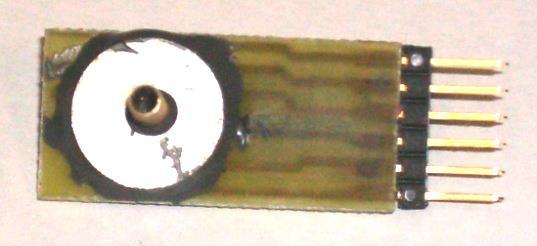
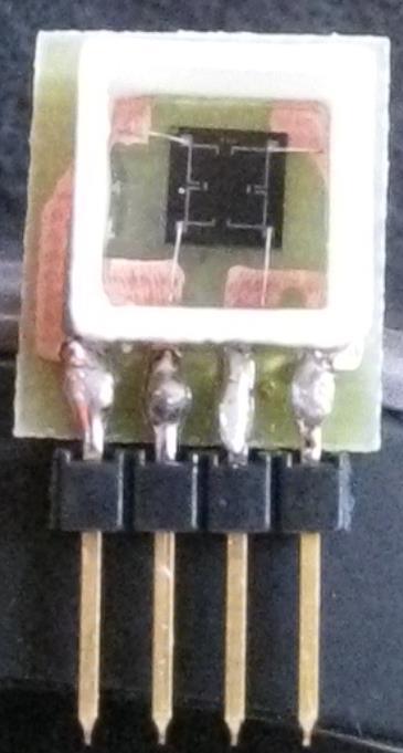
15 PRESSURE SENSOR PACKAGING Page 15


16 PRESSURE SENSOR TEST SETUP Apply pressure, measure and compare with other pressure gages. Collect data. Page 16
17 Output Voltage (mv) Pressure Sensor OUTPUT VOLTAGE VERSUS PRESSURE MEMS Pressure Sensor Output Polysilicon Resistors y = x x Pressure (psi) psi mv Page 17

18 PRESSURE SENSOR CHIP VER 3 Pressure Sensor Temperature Sensor Humidity Sensor Diffused Resistors Length = Width = Note: upper left is not connected so individual resistances can be measured. Page 18

19 ELECTRICAL MEASUREMENTS Measured resistance: Rtop = Kohm Rright = Kohm Rbottom = Kohm Rleft = Kohm Measured Voltages: Vo1 = V Vo2 = V Vo1-Vo2 = 31.0 mv Rhos ~= 150 ohm/sq Page 19

20 OUTPUT VOLTAGE VS PRESSURE Sensitivity = 0.406mV/psi/V or mv/kpa/v or VDC Page 20

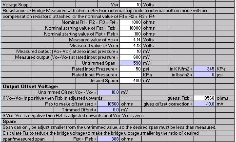
21 ZERO AND SPAN COMPENSATION Page 21
22 COMPARISON OF THIN AND THICK DIAPHRAGM Diffused Resistors Sensitivity ~ = 200mV/12psi = 10 mv/psi Sensitivity ~ = 100mV/15psi = 6.67 mv/psi 2011 Mustafa Koz Page 22

23 EXCESSIVE PRESSURE Page 23
24 Output Voltage [m Pressure Sensor Output Voltage [m EVALUATION OVER TEMPERATURE Polysilicon Resistors Output Voltage vs. Pressure for Device 2 Zero-Span Compensated Pressure Sensor over Temperature Pressure [psi] Pressure [psi] Temp - 22 C Temp - 50 C Temp - 70 C Temp - 93 C Temp C T = 27 C T = 57 C T = 84 C No Compensation Compensated Page 24

25 TEST SETUP FOR FREQUENCY MEASUREMENT Page 25

26 BALLOON ABOUT TO POP Page 26
27 MEASURED STEP RESPONSE Page 27
28 step to frequency.xls 7-Apr-07 This spread sheet finds the frequency response from the measured step response. The measured step response is converted into a series of 128 data points. The derivitive is found to get the impulse response. The fourier transform of the impulse response is found to get the frequency response. The frequency response is the real part of the fourier transform of the impulse response for positive frequencies. Assume the step responsem (Rn) has the general form shown in the figure below, enter times to, tmid, tend to = sec, where Rn = 0 tmid = sec, where Rn = 0.5 tend = sec, where Rn =1.0 normalized response, Rn to = time at start time increment = Measured Step Response tmid = time at midpoint tend = time at end Number of Samples N = 128 Normalized n t Step Impulse fourier transform freq = (n-n/2)/dt/n sample time Response response dt = number sec Rn dv/dt Real Imag freq 20Log Real E E E E E i E+03 #NUM! E E i E+03 #NUM! E E i E+03 #NUM! E E i E+03 #NUM! E E i E+03 #NUM! E E i E+03 #NUM! E E i E+03 #NUM! E E i E+03 #NUM! E E i E+03 #NUM! E E i E+03 #NUM! E E i E+03 #NUM! E E i E+03 #NUM! E E i E+03 #NUM! E E E E+03 #NUM! E E E i E+03 #NUM! E E E E+03 #NUM! E E E E+03 #NUM! E E E E+03 #NUM! E E E E E E E i E E E E E E E E E E E E E E E E E E E E E E E E E E E E i E E E E i E E E E E E E E E E E E E E E E E E E E E i E E E E E E E E E E E E E E E E E E E E E E E E E E E E E E E E E E E E E E E E E E E E E E E E E E E E E E E E E E E E E E E E E E E E E E E E E E E E E E E E E E E E E E E E E E E E E E E E E E E E E E E E E E E E E E E E E E E E E E E E E E E E E E E E E E-002i E E E-002i E E E E E E E E E E E E E E E E E E E E E E E E E E E E E E E E E E E E E E E E E E E E E E E E E E E E E E E E E E E E E E E E E E E E E E E E E E E E E i E E E E E E i E E E E E E E E E E E E E E E i E E E E E E E E E E E E E E E E E E E E E E E E E E E E E E E E E E E E E E E E i E E E E E+03 #NUM! E E E E+03 #NUM! E E E E+03 #NUM! E E E E+03 #NUM! E E E E+03 #NUM! E E i E+03 #NUM! E E i E+03 #NUM! E E i E+03 #NUM! E E i E+03 #NUM! E E i E+03 #NUM! E E i E+03 #NUM! E E i E+03 #NUM! E E i E+03 #NUM! E E i E+03 #NUM! E E i E+03 #NUM! E E i E+03 #NUM! E E i E+03 #NUM! E E i E+03 #NUM! E E E+03 time Pressure Sensor 4.50E E E E E E E E E E E E E E E E E E E E E E E E E E E E E E Normalized Step Response versus time Real part of Fourier transform versus frequency time (seconds) Impulse Response time (seconds) -45 Frequency (hz) 20 log (Real Part of Fourier Transform) versus frequency E E E E E E E+03 frequency (Hz) Measured Step Response from Oscilloscope 60 Hz noise filtered STEP TO IMPULSE TO FREQUENCY RESPONSE Excel Spreadsheet Data Filtered Normalized Step Response Derivative gives Impulse Response Fourier Transform Gives frequency response Real Part in db Page 28
29 STEP TO FREQUENCY.XLS step to frequency.xls 7-Apr-07 This spread sheet finds the frequency response from the measured step response. The measured step response is converted into a series of 128 data points. The derivitive is found to get the impulse response. The fourier transform of the impulse response is found to get the frequency response. The frequency response is the real part of the fourier transform of the impulse response for positive frequencies. Assume the step responsem (Rn) has the general form shown in the figure below, enter times to, tmid, tend to = sec, where Rn = 0 tmid = sec, where Rn = 0.5 tend = sec, where Rn =1.0 Measured Step Response normalized response, Rn time to = time at start tmid = time at midpoint tend = time at end time increment = Page 29
30 MEASURED STEP RESPONSE Measured Step Response from Oscilloscope 60 Hz noise filtered Page 30
31 FILTERED NORMALIZED STEP RESPONSE 1.20E+00 Normalized Step Response versus time 1.00E E E E E E E time (seconds) Page 31
32 IMPULSE RESPONSE 4.50E+02 Impulse Response 4.00E E E E E E E E E E time (seconds) Page 32
33 FOURIER TRANSFORM Real part of Fourier transform versus frequency E E E E E E E E E E E Frequency (hz) Page 33
34 FREQUENCY RESPONSE 0 20 log (Real Part of Fourier Transform) versus frequency E E E E E E E frequency (Hz) Page 34
35 REFERENCES Microsystem Design, Stephen D, Senturia, Kluwer Academic Publishers, 2000, pg Micromachined Transducers, McGraw Hill, 1998,Kovacs, pg Page 35
36 HOMEWORK PRESSURE SENSOR LAB 1. The example calculations shown on page 4-10 make a lot of assumptions about the fabrication process such as the starting wafer is 500um thick. In fact the starting wafer is thinned and polished to reduce the KOH etch time and the back grinding process is not that exact giving variation of starting wafer thickness between 250 and 350um. List other variables that might vary by more than 10% and discuss how that would effect the sensitivity and offset of the pressure sensor. 2. Discuss the linearity of the pressure sensor. Why do thicker diaphragms give more linear results over a given pressure range. How is the sensitivity affected by thicker diaphragms. 3. Should the pressure be applied to the top or bottom of the sensor? Why? 4. If the compensation network uses laser trimmed resistors which resistor should be trimmed to make the output zero if Vo+ is +50mV to begin with? 5. Use the bridge balance Excel spread sheet to adjust the zero and span of the pressures sensor on page 20 Page 36
37 LAB INSTRUCTORS NOTES Show MEMS chip Take Picture Apply Vacuum Take Picture Measure Vo1, Vo2 and Vo1-Vo2 with no pressure Measure Vo1, Vo2 and Vo1-Vo2 with pressure For RIT packaged device take data for Vo1-Vo2 versus Pressure Determine Offset and span Correct offset and span Take data for Vo1-Vo2 with corrections. Take data for Commercial Pressure Sensor Page 37
Evaluation of Pressure Sensor Performance Dr. Lynn Fuller
 ROCHESTER INSTITUTE OF TECHNOLOGY MICROELECTRONIC ENGINEERING Evaluation of Pressure Sensor Performance Dr. Lynn Fuller Webpage: http://people.rit.edu/lffeee 82 Lomb Memorial Drive Rochester, NY 14623-5604
Pressure Sensor Evaluation Dr. Lynn Fuller Lianna Dicke Webpage:
 ROCHESTER INSTITUTE OF TECHNOLOGY MICROELECTRONIC ENGINEERING Pressure Sensor Evaluation Lianna Dicke Webpage: http://people.rit.edu/lffeee 82 Lomb Memorial Drive Rochester, NY 14623-5604 Email: Lynn.Fuller@rit.edu
Microelectromechanical Systems (MEMs) Physical Fundamentals - Part 1 - Mechanical Fundamentals
 Physical Fundamentals - Part 1 - Mechanical Fundamentals") ROCHESTER INSTITUTE OF TEHNOLOGY MICROELECTRONIC ENGINEERING Microelectromechanical Systems (MEMs) Physical Fundamentals - Part 1 - Mechanical Fundamentals Dr. Risa Robinson Dr. Lynn Fuller Webpage: http://people.rit.edu/lffeee
ROCHESTER INSTITUTE OF TEHNOLOGY MICROELECTRONIC ENGINEERING Microelectromechanical Systems (MEMs) Physical Fundamentals - Part 1 - Mechanical Fundamentals Dr. Risa Robinson Dr. Lynn Fuller Webpage: http://people.rit.edu/lffeee
Published by: PIONEER RESEARCH & DEVELOPMENT GROUP(
 MEMS based Piezo resistive Pressure Sensor Swathi Krishnamurthy 1, K.V Meena 2, E & C Engg. Dept., The Oxford College of Engineering, Karnataka. Bangalore 560009 Abstract The paper describes the performance
v A v B V + V v S v A v B K = v S /(V + V K T = N/v S
 vs S v A v B V + V v S v A v B K = v S /(V + V K v S N T = N/v S P affiche = P S K T H u etal (S) = 50 µv/kp a P =2 R1 K u etal (K) = 0, 1 SEMICONDUCTOR TECHNICAL DATA Order this document by MPX2200/D
Piezoresistive sensors
 Perform a basic bridge analysis, specifically, find output voltage as a function of input voltage and the various resistances, and find the relationship between output voltage and changes in resistance.
Hall Effect Sensors ROCHESTER INSTITUTE OF TECHNOLOGY MICROELECTRONIC ENGINEERING
 ROCHESTER INSTITUTE OF TECHNOLOGY MICROELECTRONIC ENGINEERING Hall Effect Sensors Dr. Lynn Fuller, Corey Shay, Michell Graciani Melo Espitia Webpage: http://people.rit.edu/lffeee Electrical and 82 Lomb
Microelectromechanical Systems (MEMs) Applications Fluids
 Applications Fluids") ROCHESTER INSTITUTE OF TEHNOLOGY MICROELECTRONIC ENGINEERING Microelectromechanical Systems (MEMs) Applications Fluids Dr. Lynn Fuller Webpage: http://people.rit.edu/lffeee 82 Lomb Memorial Drive Rochester,
ROCHESTER INSTITUTE OF TEHNOLOGY MICROELECTRONIC ENGINEERING Microelectromechanical Systems (MEMs) Applications Fluids Dr. Lynn Fuller Webpage: http://people.rit.edu/lffeee 82 Lomb Memorial Drive Rochester,
MEMS Mechanical Fundamentals
 ROCHESTER INSTITUTE OF TECHNOLOGY MICROELECTRONIC ENGINEERING MEMS Mechanical Fundamentals Dr. Lynn Fuller webpage: http://people.rit.edu/lffeee Electrical and Microelectronic Engineering Rochester Institute
Outline. 4 Mechanical Sensors Introduction General Mechanical properties Piezoresistivity Piezoresistive Sensors Capacitive sensors Applications
 Sensor devices Outline 4 Mechanical Sensors Introduction General Mechanical properties Piezoresistivity Piezoresistive Sensors Capacitive sensors Applications Introduction Two Major classes of mechanical
Freescale Semiconductor
 Freescale Semiconductor Pressure Rev 14, 10/2008 + 10 kpa Uncompensated Silicon Pressure The series silicon piezoresistive pressure sensors provide a very accurate and linear voltage output, directly proportional
Piezoresistive Sensors
 Piezoresistive Sensors Outline Piezoresistivity of metal and semiconductor Gauge factor Piezoresistors Metal, silicon and polysilicon Close view of the piezoresistivity of single crystal silicon Considerations
Fundamental Theory and Design of Micro Pressure Sensor
 Chapter 4 Fundamental Theory and Design of Micro Pressure Sensor Pressure sensor fabricated in this work is based on the piezoresistors. These piezoresistors undergo a change in resistance due to the applied
Temperature Compensation for MEAS Pressure Sensors
 INTRODUCTION Advancements in microelectronic technology have pushed silicon sensors not only toward greater sophistication and lower functional cost but also in the direction of higher performance. The
200 kpa On-Chip Temperature Compensated Silicon Pressure Sensors
 Freescale Semiconductor Data Sheet: Technical Data Pressure Document Number: Rev 8, 10/2012 200 kpa On-Chip Temperature Compensated Silicon Pressure The devices series are silicon piezoresistive pressure
ORDERING INFORMATION # of Ports Pressure Type Device Name
 Rev 13, 10/2008 10 kpa On-Chip Temperature + Compensated and Calibrated Silicon Pressure The series silicon piezoresistive pressure sensors provide a very accurate and linear voltage output directly proportional
Pressure and Flow Sensors for Biological Measurements Dr. Lynn Fuller
 ROCHESTER INSTITUTE OF TECHNOLOGY MICROELECTRONIC ENGINEERING Pressure and Flow Sensors for Biological Measurements Dr. Lynn Fuller Webpage: http://people.rit.edu/lffeee 82 Lomb Memorial Drive Rochester,
Smart Phone MEMS Labs Dr. Lynn Fuller
 ROCHESTER INSTITUTE OF TECHNOLOGY MICROELECTRONIC ENGINEERING Smart Phone MEMS Labs Dr. Lynn Fuller Webpage: http://people.rit.edu/lffeee 82 Lomb Memorial Drive Rochester, NY 14623-5604 Tel (585) 475-2035
Millivolt Output Pressure Sensors
 Millivolt Output Pressure Sensors H-Grade Pressure Sensors Features 0 to 4 H2O to 0 to 100 Pressure Ranges % linearity...high accuracy version Temperature Compensated Calibrated Zero and Span General Description
TEMPERATURE COMPENSATION FOR MEAS PRESSURE SENSORS APPLICATION NOTE
 TEMPERATURE COMPENSATION FOR MEAS PRESSURE SENSORS INTRODUCTION Advancements in microelectronic technology have pushed silicon sensors not only toward greater sophistication and lower functional cost but
MEMS Electrical Fundamentals
 ROCHESTER INSTITUTE OF TECHNOLOGY MICROELECTRONIC ENGINEERING MEMS Electrical Fundamentals Dr. Lynn Fuller webpage: http://people.rit.edu/lffeee Electrical and Microelectronic Engineering Rochester Institute
SENSOR DEVICES MECHANICAL SENSORS
 SENSOR DEVICES MECHANICAL SENSORS OUTLINE 4 Mechanical Sensors Introduction General mechanical properties Piezoresistivity Piezoresistive sensors Capacitive sensors Applications INTRODUCTION MECHANICAL
10 kpa On-Chip Temperature Compensated & Calibrated Silicon Pressure Sensors
 Freescale Semiconductor Technical Data 10 kpa On-Chip Temperature Compensated & Calibrated Silicon Pressure The /MPXV2010G series silicon piezoresistive pressure sensors provide a very accurate and linear
AC : MEMS FABRICATION AS A MULTIDISCIPLINARY LABORATORY
 AC 2007-524: MEMS FABRICATION AS A MULTIDISCIPLINARY LABORATORY Todd Kaiser, Montana State University Andrew Lingley, Montana State University Matt Leone, Montana State University Brad Pierson, Montana
MOS TRANSISTOR PRESSURE SENSOR
 MOS TRANSSTOR PRESSURE SENSOR Salvador Alcantara. Antonio Cerdeira and Gabriel RomeroParedes Seccion de Elecrronica del Estadu dido. Depto. de lngenieria Elecrrica CNVESTAV PN. Av. PN No. 1508. A.P. 14740,
ELECTROMECHANICAL RELIABILITY TESTING OF THREE-AXIAL SILICON FORCE SENSORS
 ELECTROMECHANICAL RELIABILITY TESTING OF THREE-AXIAL SILICON FORCE SENSORS S. Spinner 1,2, J. Bartholomeyczik 1, B. Becker 2, M. Doelle 1, O. Paul 1, I. Polian 2, R. Roth 3, K. Seitz 3, and P. Ruther 1
Appendix A Glossary of Mathematical Symbols
 Appendix A Glossary of Mathematical Symbols This Appendix summarizes the mathematical symbols that are used throughout the book. Several symbols have multiple meanings; for example, α is used to represent
Structures - Experiment 3B Sophomore Design - Fall 2006
 Structures - Experiment 3B 1.101 Sophomore Design - Fall 2006 Linear elastic behavior of a beam. The objectives of this experiment are to experimentally study the linear elastic behavior of beams under
200 kpa On-Chip Temperature. Compensated Silicon Pressure Sensors. MPX2200 Series. Pressure. Application Examples. Features. MPX2200 Rev 13, 10/2008
 Pressure Rev 13, 10/2008 200 kpa On-Chip Temperature + Compensated ilicon Pressure The series devices are silicon piezoresistive pressure sensor providing a highly accurate and linear voltage output directly
Impact-Tek, LLC, Oil Sensors Phase 2, Design Review
 ROCHESTER INSTITUTE OF TECHNOLOGY MICROELECTRONIC ENGINEERING Impact-Tek, LLC, Oil Sensors Phase 2, Design Review Dr. Lynn Fuller Ivan Puchades Webpage: http://people.rit.edu/lffeee 82 Lomb Memorial Drive
Diode Sensors Theory
 ROCHESTER INSTITUTE OF TEHNOLOGY MICROELECTRONIC ENGINEERING Diode Sensors Theory Dr. Lynn Fuller Dr. Fuller s Webpage: http://people.rit.edu/lffeee 82 Lomb Memorial Drive Rochester, NY 14623-5604 Email:
Operating Characteristics Table 1. Operating Characteristics (V S = 3.0 Vdc, T A = 25 C unless otherwise noted, P1 > P2) Characteristic Symbol Min Typ
 Characteristic Symbol Min Typ") Freescale Semiconductor Pressure Rev 14, 10/2008 + 10 kpa Uncompensated Silicon Pressure Sensors The series silicon piezoresistive pressure sensors provide a very accurate and linear voltage output, directly
Freescale Semiconductor Pressure Rev 14, 10/2008 + 10 kpa Uncompensated Silicon Pressure Sensors The series silicon piezoresistive pressure sensors provide a very accurate and linear voltage output, directly
EE C245 / ME C218 INTRODUCTION TO MEMS DESIGN FALL 2009 PROBLEM SET #7. Due (at 7 p.m.): Thursday, Dec. 10, 2009, in the EE C245 HW box in 240 Cory.
: Thursday, Dec. 10, 2009, in the EE C245 HW box in 240 Cory.") Issued: Thursday, Nov. 24, 2009 PROBLEM SET #7 Due (at 7 p.m.): Thursday, Dec. 10, 2009, in the EE C245 HW box in 240 Cory. 1. Gyroscopes are inertial sensors that measure rotation rate, which is an extremely
Issued: Thursday, Nov. 24, 2009 PROBLEM SET #7 Due (at 7 p.m.): Thursday, Dec. 10, 2009, in the EE C245 HW box in 240 Cory. 1. Gyroscopes are inertial sensors that measure rotation rate, which is an extremely
Exercise 2: Bending Beam Load Cell
 Transducer Fundamentals The Strain Gauge Exercise 2: Bending Beam Load Cell EXERCISE OBJECTIVE When you have completed this exercise, you will be able to explain and demonstrate the operation of a board,
MEMS Capacitor Sensor Laboratory
 ROCHESTER INSTITUTE OF TEHNOLOGY MICROELECTRONIC ENGINEERING MEMS Capacitor Sensor Laboratory Dr. Lynn Fuller, Dr. Ivan Puchades Webpage: http://people.rit.edu/lffeee 82 Lomb Memorial Drive Rochester,
Modeling, Simulation and Optimization of the Mechanical Response of Micromechanical Silicon Cantilever: Application to Piezoresistive Force Sensor
 Available online at www.sciencedirect.com ScienceDirect Physics Procedia 55 (2014 ) 348 355 Eight International Conference on Material Sciences (CSM8-ISM5) Modeling, Simulation and Optimization of the
BLC Series - Basic Compact Pressure Sensor Series. Introduction
 Sensors CoBeam TM Technology. The device provides a high output Features & Applications... signal at a low operating voltage and reduces the overall supply Standard Pressure Ranges... voltage while maintaining
Exercise 1: Thermocouple Characteristics
 The Thermocouple Transducer Fundamentals Exercise 1: Thermocouple Characteristics EXERCISE OBJECTIVE When you have completed this exercise, you will be able to describe and demonstrate the characteristics
Lecture 20. Measuring Pressure and Temperature (Chapter 9) Measuring Pressure Measuring Temperature MECH 373. Instrumentation and Measurements
 Measuring Pressure Measuring Temperature MECH 373. Instrumentation and Measurements") MECH 373 Instrumentation and Measurements Lecture 20 Measuring Pressure and Temperature (Chapter 9) Measuring Pressure Measuring Temperature 1 Measuring Acceleration and Vibration Accelerometers using
MECH 373 Instrumentation and Measurements Lecture 20 Measuring Pressure and Temperature (Chapter 9) Measuring Pressure Measuring Temperature 1 Measuring Acceleration and Vibration Accelerometers using
MEMS Tuning-Fork Gyroscope Mid-Term Report Amanda Bristow Travis Barton Stephen Nary
 MEMS Tuning-Fork Gyroscope Mid-Term Report Amanda Bristow Travis Barton Stephen Nary Abstract MEMS based gyroscopes have gained in popularity for use as rotation rate sensors in commercial products like
Department of Mechanical and Aerospace Engineering. MAE334 - Introduction to Instrumentation and Computers. Final Examination.
 Name: Number: Department of Mechanical and Aerospace Engineering MAE334 - Introduction to Instrumentation and Computers Final Examination December 12, 2003 Closed Book and Notes 1. Be sure to fill in your
SCB10H Series Pressure Elements PRODUCT FAMILY SPEFICIFATION. Doc. No B
 PRODUCT FAMILY SPEFICIFATION SCB10H Series Pressure Elements SCB10H Series Pressure Elements Doc. No. 82 1250 00 B Table of Contents 1 General Description... 3 1.1 Introduction... 3 1.2 General Description...
Smartec Pressure Sensor (bridge output)
") DATASHEET Pressure sensor family 1/5 Smartec Pressure Sensor (bridge output) Features * Commercial grade * DIP version for high volume production * Gauge or absolute pressure * Resistive bridge technology
DATASHEET Pressure sensor family 1/5 Smartec Pressure Sensor (bridge output) Features * Commercial grade * DIP version for high volume production * Gauge or absolute pressure * Resistive bridge technology
Slide 1. Temperatures Light (Optoelectronics) Magnetic Fields Strain Pressure Displacement and Rotation Acceleration Electronic Sensors
 Magnetic Fields Strain Pressure Displacement and Rotation Acceleration Electronic Sensors") Slide 1 Electronic Sensors Electronic sensors can be designed to detect a variety of quantitative aspects of a given physical system. Such quantities include: Temperatures Light (Optoelectronics) Magnetic
Slide 1 Electronic Sensors Electronic sensors can be designed to detect a variety of quantitative aspects of a given physical system. Such quantities include: Temperatures Light (Optoelectronics) Magnetic
Sensors, Signals and Noise 1 COURSE OUTLINE. Introduction Signals and Noise Filtering Sensors: Strain Gauges. Signal Recovery, 2017/2018 Strain Gauges
 Sensors, Signals and Noise 1 COURSE OUTLINE Introduction Signals and Noise Filtering Sensors: Strain Gauges Strain Gauges 2 Stress and strain in elastic materials Piezoresistive Effect Strain Gauge principle
Exercise 1: Thermistor Characteristics
 Exercise 1: Thermistor Characteristics EXERCISE OBJECTIVE When you have completed this exercise, you will be able to describe and demonstrate the characteristics of thermistors. DISCUSSION A thermistor
Micro Bolometer Dr. Lynn Fuller, Jackson Anderson
 ROCHESTER INSTITUTE OF TECHNOLOGY MICROELECTRONIC ENGINEERING Micro Bolometer Dr. Lynn Fuller, Jackson Anderson Webpage: http://people.rit.edu/lffeee Electrical and 82 Lomb Memorial Drive Rochester, NY
1. Mark the correct statement(s)
") 1. Mark the correct statement(s) Figure to the right shows a mass measurement scale using a spring. 1.1 The span of the scale is a) 16 kg b) 21 kg c) 11 kg d) 5-16 kg 1.2 The range of the scale is a) 16
1. Mark the correct statement(s) Figure to the right shows a mass measurement scale using a spring. 1.1 The span of the scale is a) 16 kg b) 21 kg c) 11 kg d) 5-16 kg 1.2 The range of the scale is a) 16
EE C245 ME C218 Introduction to MEMS Design Fall 2007
 EE C245 ME C218 Introduction to MEMS Design Fall 2007 Prof. Clark T.-C. Nguyen Dept. of Electrical Engineering & Computer Sciences University of California at Berkeley Berkeley, CA 94720 Lecture 13: Material
Surface Analysis. Dr. Lynn Fuller Dr. Fuller s Webpage:
 ROCHESTER INSTITUTE OF TECHNOLOGY MICROELECTRONIC ENGINEERING Surface Analysis Dr. Lynn Fuller Dr. Fuller s Webpage: http://people.rit.edu/lffeee 82 Lomb Memorial Drive Rochester, NY 14623-5604 Tel (585)
Foundations of MEMS. Chang Liu. McCormick School of Engineering and Applied Science Northwestern University. International Edition Contributions by
 Foundations of MEMS Second Edition Chang Liu McCormick School of Engineering and Applied Science Northwestern University International Edition Contributions by Vaishali B. Mungurwadi B. V. Bhoomaraddi
Simple calibration for ceramic sensing elements using an ME651
 Simple calibration for ceramic sensing elements using an ME651 This article describes in detail a simple electronic circuit based on a suitable IC and few external components to amplify and to calibrate
Strain and Force San José State University A. Mysore Spring 2009
 Strain and Force Strain Gage Measures strain as a change in length L, observed by change in resistance R, for a given resistivity ρ and cross-sectional area A. For elastic materials that follow Hooke s
Biosensors and Instrumentation: Tutorial 2
 Biosensors and Instrumentation: Tutorial 2. One of the most straightforward methods of monitoring temperature is to use the thermal variation of a resistor... Suggest a possible problem with the use of
Diffusion and Ion implantation Reference: Chapter 4 Jaeger or Chapter 3 Ruska N & P Dopants determine the resistivity of material Note N lower
 Diffusion and Ion implantation Reference: Chapter 4 Jaeger or Chapter 3 Ruska N & P Dopants determine the resistivity of material Note N lower resistavity than p: due to higher carrier mobility Near linear
ORDERING INFORMATION. # of Ports Pressure Type No. None Single Dual Gauge Differential Absolute
 Freescale Semiconductor 200 kpa On-Chip Temperature + Compensated Silicon Pressure The devices series are silicon piezoresistive pressure sensor providing a highly accurate and linear voltage output directly
THE HALL EFFECT. Theory
 THE HALL EFFECT Theory For a charge moving in a magnetic field, it experiences a force acting at right angles to both its direction and the direction of the magnetic field H. Hence in a semiconductor,
Topics to be Covered. capacitance inductance transmission lines
 Topics to be Covered Circuit Elements Switching Characteristics Power Dissipation Conductor Sizes Charge Sharing Design Margins Yield resistance capacitance inductance transmission lines Resistance of
Integrating MEMS Electro-Static Driven Micro-Probe and Laser Doppler Vibrometer for Non-Contact Vibration Mode SPM System Design
 Tamkang Journal of Science and Engineering, Vol. 12, No. 4, pp. 399 407 (2009) 399 Integrating MEMS Electro-Static Driven Micro-Probe and Laser Doppler Vibrometer for Non-Contact Vibration Mode SPM System
1 Force Sensing. Lecture Notes. 1.1 Load Cell. 1.2 Stress and Strain
 Lecture Notes 1 Force Sensing 1.1 Load Cell A Load Cell is a structure which supports the load and deflects a known amount in response to applied forces and torques. The deflections are measured to characterize
b. The displacement of the mass due to a constant acceleration a is x=
 EE147/247A Final, Fall 2013 Page 1 /35 2 /55 NO CALCULATORS, CELL PHONES, or other electronics allowed. Show your work, and put final answers in the boxes provided. Use proper units in all answers. 1.
ELEN0037 Microelectronic IC Design. Prof. Dr. Michael Kraft
 ELEN0037 Microelectronic IC Design Prof. Dr. Michael Kraft Lecture 2: Technological Aspects Technology Passive components Active components CMOS Process Basic Layout Scaling CMOS Technology Integrated
MODELING OF T-SHAPED MICROCANTILEVER RESONATORS. Margarita Narducci, Eduard Figueras, Isabel Gràcia, Luis Fonseca, Joaquin Santander, Carles Cané
 Stresa, Italy, 5-7 April 007 MODELING OF T-SHAPED MICROCANTILEVER RESONATORS Margarita Narducci, Eduard Figueras, Isabel Gràcia, Luis Fonseca, Joaquin Santander, Carles Centro Nacional de Microelectrónica
LM34 - Precision Fahrenheit Temperature Sensor
 - Precision Fahrenheit Temperature Sensor Features Typical Application Calibrated directly in degrees Fahrenheit Linear +10.0 mv/ F scale factor 1.0 F accuracy guaranteed (at +77 F) Parametric Table Supply
Amplified Low Pressure Sensors
 Amplified Low Pressure Sensors 1 mbar (0.4 In H2O) to 60 In H2O Pressure Sensors Features 0 to 1 mbar to 0 to 60 In H2O Pressure Ranges Ratiometric 4 Output Temperature Compensated Calibrated Zero and
PHYS 2212L - Principles of Physics Laboratory II
 PHYS 2212L - Principles of Physics Laboratory II Laboratory Advanced Sheet Resistors 1. Objectives. The objectives of this laboratory are a. to verify the linear dependence of resistance upon length of
UNIVERSITY OF CALIFORNIA College of Engineering Department of Electrical Engineering and Computer Sciences. Professor Chenming Hu.
 UNIVERSITY OF CALIFORNIA College of Engineering Department of Electrical Engineering and Computer Sciences EECS 130 Spring 2009 Professor Chenming Hu Midterm I Name: Closed book. One sheet of notes is
1. Narrative Overview Questions
 Homework 4 Due Nov. 16, 010 Required Reading: Text and Lecture Slides on Downloadable from Course WEB site: http://courses.washington.edu/overney/nme498.html 1. Narrative Overview Questions Question 1
Semiconductors Reference: Chapter 4 Jaeger or Chapter 3 Ruska Recall what determines conductor, insulator and semiconductor Plot the electron energy
 Semiconductors Reference: Chapter 4 Jaeger or Chapter 3 Ruska Recall what determines conductor, insulator and semiconductor Plot the electron energy states of a material In some materials get the creation
EE C247B / ME C218 INTRODUCTION TO MEMS DESIGN SPRING 2014 PROBLEM SET #1
 Issued: Thursday, Jan. 30, 2014 PROBLEM SET #1 Due (at 9 a.m.): Wednesday Feb. 12, 2014, in the EE C247B HW box near 125 Cory. This homework assignment is intended to give you some early practice playing
New Die Attach Adhesives Enable Low-Stress MEMS Packaging
 New Die Attach Adhesives Enable Low-Stress MEMS Packaging Dr. Tobias Königer DELO Industrial Adhesives DELO-Allee 1; 86949 Windach; Germany Tobias.Koeniger@DELO.de Phone +49 8193 9900 365 Abstract High
Lecture 19. Measurement of Solid-Mechanical Quantities (Chapter 8) Measuring Strain Measuring Displacement Measuring Linear Velocity
 Measuring Strain Measuring Displacement Measuring Linear Velocity") MECH 373 Instrumentation and Measurements Lecture 19 Measurement of Solid-Mechanical Quantities (Chapter 8) Measuring Strain Measuring Displacement Measuring Linear Velocity Measuring Accepleration and
MECH 373 Instrumentation and Measurements Lecture 19 Measurement of Solid-Mechanical Quantities (Chapter 8) Measuring Strain Measuring Displacement Measuring Linear Velocity Measuring Accepleration and
Lab Exercise #5: Tension and Bending with Strain Gages
 Lab Exercise #5: Tension and Bending with Strain Gages Pre-lab assignment: Yes No Goals: 1. To evaluate tension and bending stress models and Hooke s Law. a. σ = Mc/I and σ = P/A 2. To determine material
Time-of-Flight Flow Microsensor using Free-Standing Microfilaments
 07-Rodrigues-V4 N2-AF 19.08.09 19:41 Page 84 Time-of-Flight Flow Microsensor using Free-Standing Microfilaments Roberto Jacobe Rodrigues 1,2, and Rogério Furlan 3 1 Center of Engineering and Social Sciences,
Midterm 2 PROBLEM POINTS MAX
 Midterm 2 PROBLEM POINTS MAX 1 30 2 24 3 15 4 45 5 36 1 Personally, I liked the University; they gave us money and facilities, we didn't have to produce anything. You've never been out of college. You
Modeling and Characterization of Dielectric-Charging Effects in RF MEMS Capacitive Switches
 Modeling and Characterization of Dielectric-Charging Effects in RF MEMS Capacitive Switches Xiaobin Yuan, Zhen Peng, and ames C. M. Hwang Lehigh University, Bethlehem, PA 1815 David Forehand, and Charles
Pressure Display Controller
 MODEL DW Display Controller Low The Model DW pressure controller accurately monitors and controls very low pressures. It combines in one enclosure a low pressure transducer, a digital display and two alarms
1.105 Solid Mechanics Laboratory Fall 2003
 1.105 Solid Mechanics Laboratory Fall 200 Experiment 7 Elastic Buckling. The objectives of this experiment are To study the failure of a truss structure due to local buckling of a compression member. To
Design And Analysis of Microcantilevers Type Sensor With Different Shape of Piezoresistive Patch
 Aakash Swami, Pulkit Agarwal 45 Design And Analysis of Microcantilevers Type Sensor With Different Shape of Piezoresistive Patch Aakash Swami and Pulkit Agarwal Student MNNIT Allahabad Email:aakashswami7@gmail.com
EE C245 ME C218 Introduction to MEMS Design
 EE C245 ME C218 Introduction to MEMS Design Fall 2007 Prof. Clark T.-C. Nguyen Dept. of Electrical Engineering & Computer Sciences University of California at Berkeley Berkeley, CA 94720 Lecture 12: Mechanical
Quiz #1 Practice Problem Set
 Name: Student Number: ELEC 3908 Physical Electronics Quiz #1 Practice Problem Set? Minutes January 22, 2016 - No aids except a non-programmable calculator - All questions must be answered - All questions
Strain, Force, and Pressure
 10-1 10-1 Strain, Force, and Pressure Force is that which results in acceleration (when forces don t cancel). Strain is the change in shape of an object...... usually due to some force. (Force is usually
Lecture 9. Strained-Si Technology I: Device Physics
 Strain Analysis in Daily Life Lecture 9 Strained-Si Technology I: Device Physics Background Planar MOSFETs FinFETs Reading: Y. Sun, S. Thompson, T. Nishida, Strain Effects in Semiconductors, Springer,
ABSTRACT I NTRODUCT ION
 DESIGN OF AN ION IMPLANTATION PROCESS MONITORING CHIP ON I.C.E. AND PROVIDE A METHODOLOGY FOR EVALUATION OF TESTING RESULTS. by JOSEPH J. BURKIS 5th YEAR MiCROELECTRONIC STUDENT ROCHESTER INSTITUTE OF
MODELING, DESIGN AND EXPERIMENTAL CARACHTERIZATION OF MICRO-ELECTRO ELECTRO-MECHANICAL- SYSTEMS FOR GAS- CHROMATOGRAPHIC APPLICATIONS
 MODELING, DESIGN AND EXPERIMENTAL CARACHTERIZATION OF MICRO-ELECTRO ELECTRO-MECHANICAL- SYSTEMS FOR GAS- CHROMATOGRAPHIC APPLICATIONS ENRICO COZZANI DEIS DOCTORATE CYCLE XXIII 18/01/2011 Enrico Cozzani
INF5490 RF MEMS. LN03: Modeling, design and analysis. Spring 2008, Oddvar Søråsen Department of Informatics, UoO
 INF5490 RF MEMS LN03: Modeling, design and analysis Spring 2008, Oddvar Søråsen Department of Informatics, UoO 1 Today s lecture MEMS functional operation Transducer principles Sensor principles Methods
Introduction to Strain Gage (SG) Technology
 Technology") IDMIL - Input Devices and Music Interaction Laboratory McGill University Introduction to Strain Gage (SG) Technology Carolina Brum Medeiros March 14, 2011 About this talk objective: present the essential
IDMIL - Input Devices and Music Interaction Laboratory McGill University Introduction to Strain Gage (SG) Technology Carolina Brum Medeiros March 14, 2011 About this talk objective: present the essential
Freescale Semiconductor. 100 kpa On-Chip Temperature Compensated Silicon Pressure Sensors. MPX2102 Series. Pressure. Application Examples.
 Freescale Semiconductor 100 kpa On-Chip Temperature Compensated Silicon Pressure The series devices are silicon piezoresistive pressure sensors providing a highly accurate and linear voltage output directly
INSTRUMENTATION ECE Fourth Semester. Presented By:- Sumit Grover Lect., Deptt. of ECE
 INSTRUMENTATION ECE Fourth Semester Presented By:- Sumit Grover Lect., Deptt. of ECE Detailed Contents Objectives Sensors and transducer Classification of transducers Temperature transducers Resistance
Realtime 3D stress measurement in curing epoxy packaging
 Downloaded from orbit.dtu.dk on: Dec 17, 2017 Realtime 3D stress measurement in curing epoxy packaging Richter, Jacob; Hyldgård, A.; Birkelund, Karen; Hansen, Ole; Thomsen, Erik Vilain Published in: International
CAPACITIVE MICRO PRESSURE SENSORS WITH UNDERNEATH READOUT CIRCUIT USING A STANDARD CMOS PROCESS
 Journal of the Chinese Institute of Engineers, Vol. 26, No. 2, pp. 237-241 (2003) 237 Short Paper CAPACITIVE MICRO PRESSURE SENSORS WITH UNDERNEATH READOUT CIRCUIT USING A STANDARD CMOS PROCESS Ching-Liang
Nanoelectronic Thermoelectric Energy Generation
 Nanoelectronic Thermoelectric Energy Generation Lourdes Ferre Llin l.ferre-llin.1@research.gla.ac.uk 1 Overview: Brief introduction on Thermoelectric generators. Goal of the project. Fabrication and Measurements
Reliability of 3D IC with Via-Middle TSV: Characterization and Modeling
 Reliability of 3D IC with Via-Middle TSV: Characterization and Modeling Victor Moroz *, Munkang Choi *, Geert Van der Plas, Paul Marchal, Kristof Croes, and Eric Beyne * Motivation: Build Reliable 3D IC
Core Technology Group Application Note 3 AN-3
 Measuring Capacitor Impedance and ESR. John F. Iannuzzi Introduction In power system design, capacitors are used extensively for improving noise rejection, lowering power system impedance and power supply
Institute for Electron Microscopy and Nanoanalysis Graz Centre for Electron Microscopy
 Institute for Electron Microscopy and Nanoanalysis Graz Centre for Electron Microscopy Micromechanics Ass.Prof. Priv.-Doz. DI Dr. Harald Plank a,b a Institute of Electron Microscopy and Nanoanalysis, Graz
Simple piezoresistive accelerometer
 Simple piezoresistive pressure sensor Simple piezoresistive accelerometer Simple capacitive accelerometer Cap wafer C(x)=C(x(a)) Cap wafer may be micromachined silicon, pyrex, Serves as over-range protection,
DESIGN AND FABRICATION OF THE MICRO- ACCELEROMETER USING PIEZOELECTRIC THIN FILMS
 DESIGN AND FABRICATION OF THE MICRO- ACCELEROMETER USING PIEZOELECTRIC THIN FILMS JYH-CHENG YU and FU-HSIN LAI Department of Mechanical Engineering National Taiwan University of Science and Technology
Technical Report PZT-Silicon Cantilever Benders
 Radiant Technologies, Inc. 2021 Girard SE Albuquerque, NM 876 Tel: 505-842-8007 Fax: 505-842-0366 Technical Report PZT-Silicon Cantilever Benders Subject: Displacement Measurements of Silicon Cantilevers
sensors Article Anh Vang Tran ID, Xianmin Zhang and Benliang Zhu *
 sensors Article Mechanical Structural Design of a Piezoresistive Pressure Sensor for Low-Pressure Measurement: A Computational Analysis by Increases in the Sensor Sensitivity Anh Vang Tran ID, Xianmin
The Temperature Compensation of the Silicon Piezo-Resistive Pressure Sensor Using the Half-Bridge Technique
 he emperature Compensation of the Silicon iezo-resistive ressure Sensor Using the Half-Bridge echnique K. H. eng*, C. M. Uang Department of Electronic Engineering, I-Shou University, Kaohsiung, aiwan,