MECHATRONICS CONTROL SYSTEM UNIT II
|
|
|
- Abner Wood
- 5 years ago
- Views:
Transcription
1 MECHATRONICS UNIT II CONTROL SYSTEM Prepared By Prof. Shinde Vishal Vasant Dept. of Mechanical Engg. NDMVP S Karmaveer Baburao Thakare College of Engg. Nashik Contact No E mail:- nilvasant22@gmail.com PROF. V.V.SHINDE NDMVP'S KBT COE NASHIK 19/01/2016
2 Syllabus Block Diagram Representation Open and Closed loop control system, Identification of key elements of mechatronics systems and represent into block diagram (Electro-Mechanical Systems), Concept of transfer function, Block diagram reduction principles, Applications of mechatronics systems:- Household, Automotive, Shop floor, Industrial.
3 Control A Control system performs following functions For particular input the system output can be controlled to a desired particular value. If some conditions are satisfied it can give a particular sequence of events as output corresponding to given input Actual Response Desired Response
4 Open Loop Control Output is dependent on input but controlling action is totally independent of the changes in output, is an Open Loop Control System. No feedback is used, so the controller must independently determine what signal to send to the actuator. Input Control Law u Plant Output Plant = Mathematical model of Input Amplifier + Actuator + Physical System Input = Reference / Desired Input or Set Point Input Output = Measured Output PROF. V.V.SHINDE NDMVP'S Control KBT Law COE = Mathematical NASHIK model of the Controller 19/01/2016
5 Examples of Open Loop Control
6 Advantages and Dis-advantages of Open Loop Control Advantages: Simple in construction Low cost Convenient to implement when output is difficult to measure Disadvantages: The controller never actually knows if the actuator did what it was supposed to do, i.e. it is inaccurate Unable to sense the environmental changes or disturbances
7 Close loop control system PROF. V.V.SHINDE NDMVP'S KBT COE NASHIK 19/01/2016
8 In a closed-loop control system, the actual value of the parameter being controlled is compared to the desired value. The difference in these values is known as the error. the desired value is known as the reference signal, or set point. This is compared to the signal from the measurement device, known as the feedback signal. The difference between the feedback signal and the reference signal is known as the error signal. The error signal is then modified so that it can adjust the performance of the system. PROF. V.V.SHINDE NDMVP'S KBT COE NASHIK 19/01/2016

9 Examples of Closed Loop Control
10 Examples of Automatic Closed Loop Control
11 Advantages and Dis-advantages of Closed Loop Control Advantages: Accurate, since the controller modifies and manipulates the actuating signal such that the error in the system will be zero. Self-correcting Senses the environmental changes, and disturbances in the system. Disadvantages: Complicated to design Costly Instable, since due to feedback, system tries to correct the error.
12 Key Elements in Mechatronic System

13 Key Elements in Mechatronic System: Example of Electro- Mechanical System
14 Transfer Function Models Why TF? Because it is easier / better to assess some things using classical techniques, such as gain and phase margin. How to determine TF? Derive the overning Differential Equation Assume I.C=Zero and Take Laplace transform of output Take Laplace transform of input Transfer function = L (output) / L (input)
15 Translational Mechanical Example 1 F y M mass/spring/dam system k d F 1/m 1/s 1/s
16 Translational Mechanical Example 1 Equation of motion (EOM) my dy ky f Assuming I.C 0 and taking Laplace of both sides ms 2 y s dsy s ky s f s T.F Output Input y f s s ms 2 1 ds k
17 Introduction Block diagram is a shorthand, graphical representation of a physical system, illustrating the functional relationships among its components. OR A Block Diagram is a shorthand pictorial representation of the cause-and-effect relationship of a system. PROF. V.V.SHINDE NDMVP'S KBT COE NASHIK 19/01/2016
18 The simplest form of the block diagram is the single block, with one input and one output. The interior of the rectangle representing the block usually contains a description of or the name of the element, or the symbol for the mathematical operation to be performed on the input to yield the output. The arrows represent the direction of information or signal flow. x d dt y PROF. V.V.SHINDE NDMVP'S KBT COE NASHIK 19/01/2016
19 The operations of addition and subtraction have a special representation. The block becomes a small circle, called a summing point, with the appropriate plus or minus sign associated with the arrows entering the circle. Any number of inputs may enter a summing point. The output is the algebraic sum of the inputs. Some books put a cross in the circle. PROF. V.V.SHINDE NDMVP'S KBT COE NASHIK 19/01/2016
20 Components of a Block Diagram for a Linear Time Invariant System System components are alternatively called elements of the system. Block diagram has four components: Signals System/ block Summing junction Pick-off/ Take-off point PROF. V.V.SHINDE NDMVP'S KBT COE NASHIK 19/01/2016
21 PROF. V.V.SHINDE NDMVP'S KBT COE NASHIK 19/01/2016
22 In order to have the same signal or variable be an input to more than one block or summing point, a takeoff point is used. Distributes the input signal, undiminished, to several output points. This permits the signal to proceed unaltered along several different paths to several destinations. PROF. V.V.SHINDE NDMVP'S KBT COE NASHIK 19/01/2016

23 Block Diagram: Feedback Closed loop TF Y R s s 1 s s H s Closed loop TF Y R s s s 1 s H s
24 Reduction techniques 1. Combining blocks in cascade or in parallel Moving a summing point behind a block
25 3. Moving a summing point ahead of a block 1 4. Moving a pickoff point behind a block 1 5. Moving a pickoff point ahead of a block
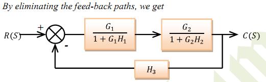
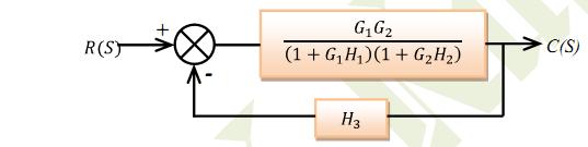
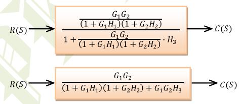
26 6. Eliminating a feedback loop H 1 H 1 H 1 7. Swap with two neighboring summing points A B B A
27 Reduction of Complicated Block Diagrams: PROF. V.V.SHINDE NDMVP'S KBT COE NASHIK 19/01/2016
28 Example 1
29 Example 1
30 Example 2
31 Example 2
32 Example 3
33 Example 3
34 Example 4
35 Example-5 Simplify the Block Diagram. PROF. V.V.SHINDE NDMVP'S KBT COE NASHIK 19/01/2016
36 Example-5: Continue. PROF. V.V.SHINDE NDMVP'S KBT COE NASHIK 19/01/2016
37 Example-6 Reduce the Block Diagram. PROF. V.V.SHINDE NDMVP'S KBT COE NASHIK 19/01/2016
38 Example-6: Continue. PROF. V.V.SHINDE NDMVP'S KBT COE NASHIK 19/01/2016
39 Example-7 Reduce the Block Diagram. H 2 R + C H 1 PROF. V.V.SHINDE NDMVP'S KBT COE NASHIK 19/01/2016
40 Example-7: R + C H H 1 PROF. V.V.SHINDE NDMVP'S KBT COE NASHIK 19/01/2016
41 Example-7: R + C H 2 1 H 1 PROF. V.V.SHINDE NDMVP'S KBT COE NASHIK 19/01/2016
42 Example-7: R + H C H 1 PROF. V.V.SHINDE NDMVP'S KBT COE NASHIK 19/01/2016
43 Example-7: H 2 1 R + _ + _ 1 H C PROF. V.V.SHINDE NDMVP'S KBT COE NASHIK 19/01/2016
44 Example-7: H 2 1 R + _ + _ H C PROF. V.V.SHINDE NDMVP'S KBT COE NASHIK 19/01/2016
45 Example-7: R + _ H H C PROF. V.V.SHINDE NDMVP'S KBT COE NASHIK 19/01/2016
46 Example-7: R H H C PROF. V.V.SHINDE NDMVP'S KBT COE NASHIK 19/01/2016
47 Applications of Mechatronic System Household Refrigerator Washing m/c Microwave Automotive Fuel injection system Power steering Air conditioner Shop floor Tool monitoring system Automated guided vehicle Conveyor system Bottle filing plant.

48 Fuel Injection
49 Electric Power Steering
Automatic Control Systems
 Automatic Control Sytem Lecture- Block Diagram Reduction Emam Fathy Department of Electrical and Control Engineering email: emfmz@yahoo.com Introduction A Block Diagram i a horthand pictorial repreentation
SECTION 2: BLOCK DIAGRAMS & SIGNAL FLOW GRAPHS
 SECTION 2: BLOCK DIAGRAMS & SIGNAL FLOW GRAPHS MAE 4421 Control of Aerospace & Mechanical Systems 2 Block Diagram Manipulation Block Diagrams 3 In the introductory section we saw examples of block diagrams
Study Material. CONTROL SYSTEM ENGINEERING (As per SCTE&VT,Odisha new syllabus) 4th Semester Electronics & Telecom Engineering
 4th Semester Electronics & Telecom Engineering") Study Material CONTROL SYSTEM ENGINEERING (As per SCTE&VT,Odisha new syllabus) 4th Semester Electronics & Telecom Engineering By Sri Asit Kumar Acharya, Lecturer ETC, Govt. Polytechnic Dhenkanal & Sri
Study Material CONTROL SYSTEM ENGINEERING (As per SCTE&VT,Odisha new syllabus) 4th Semester Electronics & Telecom Engineering By Sri Asit Kumar Acharya, Lecturer ETC, Govt. Polytechnic Dhenkanal & Sri
4 Arithmetic of Feedback Loops
 ME 132, Spring 2005, UC Berkeley, A. Packard 18 4 Arithmetic of Feedback Loops Many important guiding principles of feedback control systems can be derived from the arithmetic relations, along with their
(Refer Slide Time: 1:42)
") Control Engineering Prof. Madan Gopal Department of Electrical Engineering Indian Institute of Technology, Delhi Lecture - 21 Basic Principles of Feedback Control (Contd..) Friends, let me get started
Control Engineering Prof. Madan Gopal Department of Electrical Engineering Indian Institute of Technology, Delhi Lecture - 21 Basic Principles of Feedback Control (Contd..) Friends, let me get started
Chapter 3: Block Diagrams and Signal Flow Graphs
 Chapter 3: Block Diagrams and Signal Flow Graphs Farid Golnaraghi, Simon Fraser University Benjamin C. Kuo, University of Illinois ISBN: 978 0 470 04896 2 Introduction In this chapter, we discuss graphical
Control Systems. EC / EE / IN. For
 Control Systems For EC / EE / IN By www.thegateacademy.com Syllabus Syllabus for Control Systems Basic Control System Components; Block Diagrammatic Description, Reduction of Block Diagrams. Open Loop
EC CONTROL SYSTEM UNIT I- CONTROL SYSTEM MODELING
 EC 2255 - CONTROL SYSTEM UNIT I- CONTROL SYSTEM MODELING 1. What is meant by a system? It is an arrangement of physical components related in such a manner as to form an entire unit. 2. List the two types
(Refer Slide Time: 00:01:30 min)
") Control Engineering Prof. M. Gopal Department of Electrical Engineering Indian Institute of Technology, Delhi Lecture - 3 Introduction to Control Problem (Contd.) Well friends, I have been giving you various
Control Engineering Prof. M. Gopal Department of Electrical Engineering Indian Institute of Technology, Delhi Lecture - 3 Introduction to Control Problem (Contd.) Well friends, I have been giving you various
Chapter 8. Feedback Controllers. Figure 8.1 Schematic diagram for a stirred-tank blending system.
 Feedback Controllers Figure 8.1 Schematic diagram for a stirred-tank blending system. 1 Basic Control Modes Next we consider the three basic control modes starting with the simplest mode, proportional
Block Diagrams and VisSim
 Block iagrams Block iagrams and VisSim Block iagrams are a graphical way to describe how dynamic systems are interconnected. They help explain how a control system will be built and how the signals flow
Electrical Machine & Automatic Control (EEE-409) (ME-II Yr) UNIT-3 Content: Signals u(t) = 1 when t 0 = 0 when t <0
 (ME-II Yr) UNIT-3 Content: Signals u(t) = 1 when t 0 = 0 when t <0") Electrical Machine & Automatic Control (EEE-409) (ME-II Yr) UNIT-3 Content: Modeling of Mechanical : linear mechanical elements, force-voltage and force current analogy, and electrical analog of simple
Electrical Machine & Automatic Control (EEE-409) (ME-II Yr) UNIT-3 Content: Modeling of Mechanical : linear mechanical elements, force-voltage and force current analogy, and electrical analog of simple
Computational Fluid Dynamics Prof. Dr. Suman Chakraborty Department of Mechanical Engineering Indian Institute of Technology, Kharagpur
 Computational Fluid Dynamics Prof. Dr. Suman Chakraborty Department of Mechanical Engineering Indian Institute of Technology, Kharagpur Lecture No. #12 Fundamentals of Discretization: Finite Volume Method
Computational Fluid Dynamics Prof. Sreenivas Jayanti Department of Computer Science and Engineering Indian Institute of Technology, Madras
 Computational Fluid Dynamics Prof. Sreenivas Jayanti Department of Computer Science and Engineering Indian Institute of Technology, Madras Lecture 46 Tri-diagonal Matrix Algorithm: Derivation In the last
EE C128 / ME C134 Feedback Control Systems
 EE C128 / ME C134 Feedback Control Systems Lecture Additional Material Introduction to Model Predictive Control Maximilian Balandat Department of Electrical Engineering & Computer Science University of
Alireza Mousavi Brunel University
 Alireza Mousavi Brunel University 1 » Control Process» Control Systems Design & Analysis 2 Open-Loop Control: Is normally a simple switch on and switch off process, for example a light in a room is switched
Lecture 12. AO Control Theory
 Lecture 12 AO Control Theory Claire Max with many thanks to Don Gavel and Don Wiberg UC Santa Cruz February 18, 2016 Page 1 What are control systems? Control is the process of making a system variable
MATH ALGEBRA AND FUNCTIONS
 Students: 1. Use letters, boxes, or other symbols to stand for any number in simple expressions or equations. 1. Students use and interpret variables, mathematical symbols and properties to write and simplify
SCHOOL OF MATHEMATICS MATHEMATICS FOR PART I ENGINEERING. Self-paced Course
 SCHOOL OF MATHEMATICS MATHEMATICS FOR PART I ENGINEERING Self-paced Course MODULE ALGEBRA Module Topics Simplifying expressions and algebraic functions Rearranging formulae Indices 4 Rationalising a denominator
CHAPTER 5 : REDUCTION OF MULTIPLE SUBSYSTEMS
 CHAPTER 5 : REDUCTION OF MULTIPLE SUBSYSTEMS Objectives Students should be able to: Reduce a block diagram of multiple subsystems to a single block representing the transfer function from input to output
COOKBOOK KVL AND KCL A COMPLETE GUIDE
 1250 COOKBOOK KVL AND KCL A COMPLETE GUIDE Example circuit: 1) Label all source and component values with a voltage drop measurement (+,- ) and a current flow measurement (arrow): By the passive sign convention,
Subject: Introduction to Process Control. Week 01, Lectures 01 02, Spring Content
 v CHEG 461 : Process Dynamics and Control Subject: Introduction to Process Control Week 01, Lectures 01 02, Spring 2014 Dr. Costas Kiparissides Content 1. Introduction to Process Dynamics and Control 2.
(Refer Slide Time: 2:11)
") Control Engineering Prof. Madan Gopal Department of Electrical Engineering Indian institute of Technology, Delhi Lecture - 40 Feedback System Performance based on the Frequency Response (Contd.) The summary
Control Engineering Prof. Madan Gopal Department of Electrical Engineering Indian institute of Technology, Delhi Lecture - 40 Feedback System Performance based on the Frequency Response (Contd.) The summary
Dr Ian R. Manchester Dr Ian R. Manchester AMME 3500 : Review
 Week Date Content Notes 1 6 Mar Introduction 2 13 Mar Frequency Domain Modelling 3 20 Mar Transient Performance and the s-plane 4 27 Mar Block Diagrams Assign 1 Due 5 3 Apr Feedback System Characteristics
Fig R 1fGH E 1 -=- R 1kGH B GH DGH k NGH = 0 (7.6)
") 156 BLOCK DIAGRAM ALGEBRA AND TRANSFER FUNCTIONS OF SYSTEMS [CHAP. 7 7.4 CANONICAL FORM OF A FEEDBACK CONTROL SYSTEM The two blocks in the forward path of the feedback system of Fig. 7-2 may be combined.
156 BLOCK DIAGRAM ALGEBRA AND TRANSFER FUNCTIONS OF SYSTEMS [CHAP. 7 7.4 CANONICAL FORM OF A FEEDBACK CONTROL SYSTEM The two blocks in the forward path of the feedback system of Fig. 7-2 may be combined.
Lecture 1: Introduction to System Modeling and Control. Introduction Basic Definitions Different Model Types System Identification
 Lecture 1: Introduction to System Modeling and Control Introduction Basic Definitions Different Model Types System Identification What is Mathematical Model? A set of mathematical equations (e.g., differential
Analysis and Design of Control Systems in the Time Domain
 Chapter 6 Analysis and Design of Control Systems in the Time Domain 6. Concepts of feedback control Given a system, we can classify it as an open loop or a closed loop depends on the usage of the feedback.
Chapter 9 Moment of Inertia
 Chapter 9 Moment of Inertia Dr. Khairul Salleh Basaruddin Applied Mechanics Division School of Mechatronic Engineering Universiti Malaysia Perlis (UniMAP) khsalleh@unimap.edu.my PARALLEL-AXIS THEOREM,
Control of Manufacturing Processes
 Control of Manufacturing Processes Subject 2.830 Spring 2004 Lecture #18 Basic Control Loop Analysis" April 15, 2004 Revisit Temperature Control Problem τ dy dt + y = u τ = time constant = gain y ss =
Solution to exam in PEF3006 Process Control at Telemark University College
 Solution to exam in PEF3006 Process Control at Telemark University College Exam date: 7. December 2015. Duration: 4 hours. Weight in final grade of the course: 100%. Teacher: Finn Aakre Haugen (finn.haugen@hit.no).
Course Summary. The course cannot be summarized in one lecture.
 Course Summary Unit 1: Introduction Unit 2: Modeling in the Frequency Domain Unit 3: Time Response Unit 4: Block Diagram Reduction Unit 5: Stability Unit 6: Steady-State Error Unit 7: Root Locus Techniques
LECTURE TWO BLOCK DIAGRAM REDUCTION
 3rd Yearomputer ommunication EngineeringU ontrol Theory LETUE TWO BLOK DIAGAM EDUTION Block diagram is a pictorial representation of a control system showing interrelation between the transfer function
Chapter 1 Basic Characteristics of Control Systems and their Representation Process and Instrument Diagrams
 Chapter 1 Basic Characteristics of Control Systems and their Representation Process and Instrument Diagrams We need ways to describe process control systems. We will learn several ways in this course.
Physics 121 for Majors
 Physics 121 for Majors 121M Tutors Tutorial Lab N-304 ESC Ethan Fletcher: M 1pm 3pm, T 3-6 pm, Th 3-10 pm, W 7-9pm, F 3pm 6-10 pm Spencer Vogel: M 1-4pm, W 1-5pm, F1-3 pm Schedule Do Post-Class Check #4
School of Engineering Faculty of Built Environment, Engineering, Technology & Design
 Module Name and Code : ENG60803 Real Time Instrumentation Semester and Year : Semester 5/6, Year 3 Lecture Number/ Week : Lecture 3, Week 3 Learning Outcome (s) : LO5 Module Co-ordinator/Tutor : Dr. Phang
Video 5.1 Vijay Kumar and Ani Hsieh
 Video 5.1 Vijay Kumar and Ani Hsieh Robo3x-1.1 1 The Purpose of Control Input/Stimulus/ Disturbance System or Plant Output/ Response Understand the Black Box Evaluate the Performance Change the Behavior
ME 132, Dynamic Systems and Feedback. Class Notes. Spring Instructor: Prof. A Packard
 ME 132, Dynamic Systems and Feedback Class Notes by Andrew Packard, Kameshwar Poolla & Roberto Horowitz Spring 2005 Instructor: Prof. A Packard Department of Mechanical Engineering University of California
STANDARDS OF LEARNING CONTENT REVIEW NOTES. ALGEBRA I Part II 1 st Nine Weeks,
 STANDARDS OF LEARNING CONTENT REVIEW NOTES ALGEBRA I Part II 1 st Nine Weeks, 2016-2017 OVERVIEW Algebra I Content Review Notes are designed by the High School Mathematics Steering Committee as a resource
Selamat Kembali Ke Parit Raja.. BDA30703 Kejuruteraan Kawalan Seksyen S5
 PROFESOR MADYA DR. ZAMRI BIN OMAR Timbalan Dekan (Hal Ehwal Pelajar & Alumni) Fakulti Kejuruteraan Mekanikal & Pembuatan Selamat Kembali Ke Parit Raja.. BDA30703 Kejuruteraan Kawalan Seksyen S5 Email :
IC6501 CONTROL SYSTEMS
 DHANALAKSHMI COLLEGE OF ENGINEERING CHENNAI DEPARTMENT OF ELECTRICAL AND ELECTRONICS ENGINEERING YEAR/SEMESTER: II/IV IC6501 CONTROL SYSTEMS UNIT I SYSTEMS AND THEIR REPRESENTATION 1. What is the mathematical
Control System. Contents
 Contents Chapter Topic Page Chapter- Chapter- Chapter-3 Chapter-4 Introduction Transfer Function, Block Diagrams and Signal Flow Graphs Mathematical Modeling Control System 35 Time Response Analysis of
feedback cannot be maintained. If loop 2 is reduced, the signal between G
 ME 3600 Control Systems Block Diagram eduction Examples Example :.C. Dorf and.h. Bishop, Modern Control Systems, th Ed., Pearson Prentice-Hall, 008. Given: The system shown in the block diagram has one
Overview of the Seminar Topic
 Overview of the Seminar Topic Simo Särkkä Laboratory of Computational Engineering Helsinki University of Technology September 17, 2007 Contents 1 What is Control Theory? 2 History
Goals for today 2.004
 Goals for today Block diagrams revisited Block diagram components Block diagram cascade Summing and pickoff junctions Feedback topology Negative vs positive feedback Example of a system with feedback Derivation
EECE 301 Signals & Systems Prof. Mark Fowler
 EECE 3 Signals & Systems Prof. Mark Fowler Note Set #9 C-T Systems: Laplace Transform Transfer Function Reading Assignment: Section 6.5 of Kamen and Heck /7 Course Flow Diagram The arrows here show conceptual
MATHEMATICAL MODELING OF CONTROL SYSTEMS
 1 MATHEMATICAL MODELING OF CONTROL SYSTEMS Sep-14 Dr. Mohammed Morsy Outline Introduction Transfer function and impulse response function Laplace Transform Review Automatic control systems Signal Flow
Uncertainty and Robustness for SISO Systems
 Uncertainty and Robustness for SISO Systems ELEC 571L Robust Multivariable Control prepared by: Greg Stewart Outline Nature of uncertainty (models and signals). Physical sources of model uncertainty. Mathematical
Acceleration Feedback
 Acceleration Feedback Mechanical Engineer Modeling & Simulation Electro- Mechanics Electrical- Electronics Engineer Sensors Actuators Computer Systems Engineer Embedded Control Controls Engineer Mechatronic
z Transform System Analysis
 z Transform System Analysis Block Diagrams and Transfer Functions Just as with continuous-time systems, discrete-time systems are conveniently described by block diagrams and transfer functions can be
Stability of Feedback Control Systems: Absolute and Relative
 Stability of Feedback Control Systems: Absolute and Relative Dr. Kevin Craig Greenheck Chair in Engineering Design & Professor of Mechanical Engineering Marquette University Stability: Absolute and Relative
Number of (Nested) Shopping Carts Three nested shopping carts are shown.
 Shopping Carts Three nested shopping carts are shown.") Randy must fit shopping carts into an area that has a length of 82 feet and a width of one shopping cart. He made some measurements necessary for his computations. The table shows the length of a set of
Randy must fit shopping carts into an area that has a length of 82 feet and a width of one shopping cart. He made some measurements necessary for his computations. The table shows the length of a set of
Lecture 25: Tue Nov 27, 2018
 Lecture 25: Tue Nov 27, 2018 Reminder: Lab 3 moved to Tuesday Dec 4 Lecture: review time-domain characteristics of 2nd-order systems intro to control: feedback open-loop vs closed-loop control intro to
Binary addition (1-bit) P Q Y = P + Q Comments Carry = Carry = Carry = Carry = 1 P Q
 P Q Y = P + Q Comments Carry = Carry = Carry = Carry = 1 P Q") Digital Arithmetic In Chapter 2, we have discussed number systems such as binary, hexadecimal, decimal, and octal. We have also discussed sign representation techniques, for example, sign-bit representation
Digital Arithmetic In Chapter 2, we have discussed number systems such as binary, hexadecimal, decimal, and octal. We have also discussed sign representation techniques, for example, sign-bit representation
Addition, Subtraction, Multiplication, and Division
 5. OA Write and interpret numerical expression. Use parentheses, brackets, or braces in numerical expressions, and evaluate expressions with these symbols. Write simple expressions that record calculations
EE 422G - Signals and Systems Laboratory
 EE 4G - Signals and Systems Laboratory Lab 9 PID Control Kevin D. Donohue Department of Electrical and Computer Engineering University of Kentucky Lexington, KY 40506 April, 04 Objectives: Identify the
Power Systems Control Prof. Wonhee Kim. Modeling in the Frequency and Time Domains
 Power Systems Control Prof. Wonhee Kim Modeling in the Frequency and Time Domains Laplace Transform Review - Laplace transform - Inverse Laplace transform 2 Laplace Transform Review 3 Laplace Transform
Fuzzy Control Systems Process of Fuzzy Control
 Fuzzy Control Systems The most widespread use of fuzzy logic today is in fuzzy control applications. Across section of applications that have successfully used fuzzy control includes: Environmental Control
User Requirements, Modelling e Identification. Lezione 1 prj Mesa (Prof. Ing N. Muto)
") User Requirements, Modelling e Identification. Lezione 1 prj Mesa (Prof. Ing N. Muto) 1.1 Introduction: A customer has requested the establishment of a system for the automatic orientation of a string
User Requirements, Modelling e Identification. Lezione 1 prj Mesa (Prof. Ing N. Muto) 1.1 Introduction: A customer has requested the establishment of a system for the automatic orientation of a string
Alireza Mousavi Brunel University
 Alireza Mousavi Brunel University 1 » Online Lecture Material at (www.brunel.ac.uk/~emstaam)» C. W. De Silva, Modelling and Control of Engineering Systems, CRC Press, Francis & Taylor, 2009.» M. P. Groover,
Expressions, Equations and Inequalities Guided Notes
 Expressions, Equations and Inequalities Guided Notes Standards: Alg1.M.A.SSE.A.01a - The Highly Proficient student can explain the context of different parts of a formula presented as a complicated expression.
Polynomial one or more monomials added or subtracted. (i.e. : 5x or 6xy-3 or 6xy - 5x + 3 or
 Polynomials Necessary Terms for Success Welcome back! We will now tackle the world of polynomials. Before we get started with performing operations or using polynomials for applications, we will need some
Designing Information Devices and Systems I Spring 2018 Lecture Notes Note Introduction to Linear Algebra the EECS Way
 EECS 16A Designing Information Devices and Systems I Spring 018 Lecture Notes Note 1 1.1 Introduction to Linear Algebra the EECS Way In this note, we will teach the basics of linear algebra and relate
20.6. Transfer Functions. Introduction. Prerequisites. Learning Outcomes
 Transfer Functions 2.6 Introduction In this Section we introduce the concept of a transfer function and then use this to obtain a Laplace transform model of a linear engineering system. (A linear engineering
EE 474 Lab Part 2: Open-Loop and Closed-Loop Control (Velocity Servo)
") Contents EE 474 Lab Part 2: Open-Loop and Closed-Loop Control (Velocity Servo) 1 Introduction 1 1.1 Discovery learning in the Controls Teaching Laboratory.............. 1 1.2 A Laboratory Notebook...............................
Contents EE 474 Lab Part 2: Open-Loop and Closed-Loop Control (Velocity Servo) 1 Introduction 1 1.1 Discovery learning in the Controls Teaching Laboratory.............. 1 1.2 A Laboratory Notebook...............................
General procedure for formulation of robot dynamics STEP 1 STEP 3. Module 9 : Robot Dynamics & controls
 Module 9 : Robot Dynamics & controls Lecture 32 : General procedure for dynamics equation forming and introduction to control Objectives In this course you will learn the following Lagrangian Formulation
(a) Torsional spring-mass system. (b) Spring element.
 Torsional spring-mass system. (b) Spring element.") m v s T s v a (a) T a (b) T a FIGURE 2.1 (a) Torsional spring-mass system. (b) Spring element. by ky Wall friction, b Mass M k y M y r(t) Force r(t) (a) (b) FIGURE 2.2 (a) Spring-mass-damper system. (b)
m v s T s v a (a) T a (b) T a FIGURE 2.1 (a) Torsional spring-mass system. (b) Spring element. by ky Wall friction, b Mass M k y M y r(t) Force r(t) (a) (b) FIGURE 2.2 (a) Spring-mass-damper system. (b)
MODELING OF CONTROL SYSTEMS
 1 MODELING OF CONTROL SYSTEMS Feb-15 Dr. Mohammed Morsy Outline Introduction Differential equations and Linearization of nonlinear mathematical models Transfer function and impulse response function Laplace
Standards addressed in this unit:
 Unit 4 Linear Equations, Inequalities and Functions Standards addressed in this unit: 1. Solve equations and inequalities arising from a context 2. Solve equations and inequalities using algebraic manipulations
COLLEGE PHYSICS. Chapter 1 INTRODUCTION: THE NATURE OF SCIENCE AND PHYSICS. Lesson 2
 COLLEGE PHYSICS Chapter 1 INTRODUCTION: THE NATURE OF SCIENCE AND PHYSICS Lesson 2 Video Narrated by Jason Harlow, Physics Department, University of Toronto MEASUREMENTS Here are two different kinds of
CHAPTER 5 ROBUSTNESS ANALYSIS OF THE CONTROLLER
 114 CHAPTER 5 ROBUSTNESS ANALYSIS OF THE CONTROLLER 5.1 INTRODUCTION Robust control is a branch of control theory that explicitly deals with uncertainty in its approach to controller design. It also refers
The Hurewicz Theorem
 The Hurewicz Theorem April 5, 011 1 Introduction The fundamental group and homology groups both give extremely useful information, particularly about path-connected spaces. Both can be considered as functors,
Algebra I Notes Unit Five: Linear Inequalities in One Variable and Absolute Value Equations & Inequalities
 Syllabus Objective 4.4 The student will solve linear inequalities and represent the solution graphically on a number line and algebraically. Inequality Symbols: < less than less than or equal to > greater
33. SOLVING LINEAR INEQUALITIES IN ONE VARIABLE
 get the complete book: http://wwwonemathematicalcatorg/getfulltextfullbookhtm 33 SOLVING LINEAR INEQUALITIES IN ONE VARIABLE linear inequalities in one variable DEFINITION linear inequality in one variable
Automatic Control A. A.A. 2016/2017 July 7, Corso di Laurea Magistrale in Ingegneria Meccanica. Prof. Luca Bascetta.
 Corso di Laurea Magistrale in Ingegneria Meccanica Automatic Control A Prof. Luca Bascetta A.A. 2016/2017 July 7, 2017 Name: Surname: University ID number: Signature: This file consists of 8 pages (including
Class 27: Block Diagrams
 Class 7: Block Diagrams Dynamic Behavior and Stability of Closed-Loop Control Systems We no ant to consider the dynamic behavior of processes that are operated using feedback control. The combination of
Lecture 12. Upcoming labs: Final Exam on 12/21/2015 (Monday)10:30-12:30
10:30-12:30") 289 Upcoming labs: Lecture 12 Lab 20: Internal model control (finish up) Lab 22: Force or Torque control experiments [Integrative] (2-3 sessions) Final Exam on 12/21/2015 (Monday)10:30-12:30 Today: Recap
289 Upcoming labs: Lecture 12 Lab 20: Internal model control (finish up) Lab 22: Force or Torque control experiments [Integrative] (2-3 sessions) Final Exam on 12/21/2015 (Monday)10:30-12:30 Today: Recap
Analysis and Synthesis of Single-Input Single-Output Control Systems
 Lino Guzzella Analysis and Synthesis of Single-Input Single-Output Control Systems l+kja» \Uja>)W2(ja»\ um Contents 1 Definitions and Problem Formulations 1 1.1 Introduction 1 1.2 Definitions 1 1.2.1 Systems
J א א J א א א F א א א א
 J CHAPTER # 4 SIGNAL FLOW GRAPH (SFG) 1. Introduction For complex control systems, the block diagram reduction technique is cumbersome. An alternative method for determining the relationship between system
CDS 101/110a: Lecture 10-1 Robust Performance
 CDS 11/11a: Lecture 1-1 Robust Performance Richard M. Murray 1 December 28 Goals: Describe how to represent uncertainty in process dynamics Describe how to analyze a system in the presence of uncertainty
Trajectory planning and feedforward design for electromechanical motion systems version 2
 2 Trajectory planning and feedforward design for electromechanical motion systems version 2 Report nr. DCT 2003-8 Paul Lambrechts Email: P.F.Lambrechts@tue.nl April, 2003 Abstract This report considers
Chapter 8: Algebra Part 2
 Chapter 8: Algebra Part 2 Section 8.1 Algebraic Products Expanding brackets means to remove the brackets. How would we expand the following? 5 (x + 2) The term which is outside the brackets must be multiplied
Physics 6303 Lecture 2 August 22, 2018
 Physics 6303 Lecture 2 August 22, 2018 LAST TIME: Coordinate system construction, covariant and contravariant vector components, basics vector review, gradient, divergence, curl, and Laplacian operators
Analyzing the Stability Robustness of Interval Polynomials
 1 Analyzing the Stability Robustness of Interval Polynomials Prof. Guy Beale Electrical and Computer Engineering Department George Mason University Correspondence concerning this paper should be sent to
Designing Information Devices and Systems I Fall 2018 Lecture Notes Note Introduction to Linear Algebra the EECS Way
 EECS 16A Designing Information Devices and Systems I Fall 018 Lecture Notes Note 1 1.1 Introduction to Linear Algebra the EECS Way In this note, we will teach the basics of linear algebra and relate it
Introduction to Controls
 EE 474 Review Exam 1 Name Answer each of the questions. Show your work. Note were essay-type answers are requested. Answer with complete sentences. Incomplete sentences will count heavily against the grade.
Algebra Mat: Working Towards Year 6
 Algebra Mat: Working Towards Year 6 at 3 and adds 3 each time. 5, 10, 15, 20, Use simple formulae. The perimeter of a rectangle = a + a + b + b a = a b = 2, cd = 6, find 2 different pairs of numbers for
CALC 2 CONCEPT PACKET Complete
 CALC 2 CONCEPT PACKET Complete Written by Jeremy Robinson, Head Instructor Find Out More +Private Instruction +Review Sessions WWW.GRADEPEAK.COM Need Help? Online Private Instruction Anytime, Anywhere
EE Experiment 11 The Laplace Transform and Control System Characteristics
 EE216:11 1 EE 216 - Experiment 11 The Laplace Transform and Control System Characteristics Objectives: To illustrate computer usage in determining inverse Laplace transforms. Also to determine useful signal
Chapter 3 Data Acquisition and Manipulation
 1 Chapter 3 Data Acquisition and Manipulation In this chapter we introduce z transf orm, or the discrete Laplace Transform, to solve linear recursions. Section 3.1 z-transform Given a data stream x {x
Control 2. Proportional and Integral control
 Control 2 Proportional and Integral control 1 Disturbance rejection in Proportional Control Θ i =5 + _ Controller K P =20 Motor K=2.45 Θ o Consider first the case where the motor steadystate gain = 2.45
Linear State Feedback Controller Design
 Assignment For EE5101 - Linear Systems Sem I AY2010/2011 Linear State Feedback Controller Design Phang Swee King A0033585A Email: king@nus.edu.sg NGS/ECE Dept. Faculty of Engineering National University
Algebra I Notes Unit Two: Variables
 Syllabus Objectives:. The student will use order of operations to evaluate expressions.. The student will evaluate formulas and algebraic expressions using rational numbers (with and without technology).
Lecture Notes on DC Network Theory
 Federal University, Ndufu-Alike, Ikwo Department of Electrical/Electronics and Computer Engineering (ECE) Faculty of Engineering and Technology Lecture Notes on DC Network Theory Harmattan Semester by
CYBER EXPLORATION LABORATORY EXPERIMENTS
 CYBER EXPLORATION LABORATORY EXPERIMENTS 1 2 Cyber Exploration oratory Experiments Chapter 2 Experiment 1 Objectives To learn to use MATLAB to: (1) generate polynomial, (2) manipulate polynomials, (3)
Chapter 1: Logic systems
 Chapter 1: Logic systems 1: Logic gates Learning Objectives: At the end of this topic you should be able to: identify the symbols and truth tables for the following logic gates: NOT AND NAND OR NOR XOR
Übersetzungshilfe / Translation aid (English) To be returned at the end of the exam!
 To be returned at the end of the exam!") Prüfung Regelungstechnik I (Control Systems I) Prof. Dr. Lino Guzzella 3.. 24 Übersetzungshilfe / Translation aid (English) To be returned at the end of the exam! Do not mark up this translation aid -
Prüfung Regelungstechnik I (Control Systems I) Prof. Dr. Lino Guzzella 3.. 24 Übersetzungshilfe / Translation aid (English) To be returned at the end of the exam! Do not mark up this translation aid -
Mechanics, Heat, Oscillations and Waves Prof. V. Balakrishnan Department of Physics Indian Institute of Technology, Madras
 Mechanics, Heat, Oscillations and Waves Prof. V. Balakrishnan Department of Physics Indian Institute of Technology, Madras Lecture - 21 Central Potential and Central Force Ready now to take up the idea
Modeling and Control Overview
 Modeling and Control Overview D R. T A R E K A. T U T U N J I A D V A N C E D C O N T R O L S Y S T E M S M E C H A T R O N I C S E N G I N E E R I N G D E P A R T M E N T P H I L A D E L P H I A U N I
Optimal Polynomial Control for Discrete-Time Systems
 1 Optimal Polynomial Control for Discrete-Time Systems Prof Guy Beale Electrical and Computer Engineering Department George Mason University Fairfax, Virginia Correspondence concerning this paper should
Analog Integrated Circuit Design Prof. Nagendra Krishnapura Department of Electrical Engineering Indian Institute of Technology, Madras
 Analog Integrated Circuit Design Prof. Nagendra Krishnapura Department of Electrical Engineering Indian Institute of Technology, Madras Lecture No - 42 Fully Differential Single Stage Opamp Hello and welcome