Video 5.1 Vijay Kumar and Ani Hsieh
|
|
|
- Collin O’Neal’
- 5 years ago
- Views:
Transcription

1 Video 5.1 Vijay Kumar and Ani Hsieh Robo3x-1.1 1


2 The Purpose of Control Input/Stimulus/ Disturbance System or Plant Output/ Response Understand the Black Box Evaluate the Performance Change the Behavior Robo3x-1.1 2
3 Anatomy of a Feedback Control System Disturbance Input Desired Speed + - Controller Actuator Gas Pedal + + Output Vehicle Speed Sensor Robo3x-1.1 3
4 Twin Objectives of Control Performance Disturbance Rejection Robo3x-1.1 4
5 Learning Objectives for this Week Linear Control Modeling in the frequency domain Transfer Functions Feedback and Feedforward Control Robo3x-1.1 5
6 Frequency Domain Modeling Algebraic vs Differential Equations Laplace Transforms Diagrams Robo3x-1.1 6

7 Laplace Transforms Integral Transform that maps functions from the time domain to the frequency domain with Robo3x-1.1 7


8 Example Let, compute Robo3x-1.1 8

9 Inverse Laplace Transforms Integral Transform that maps functions from the frequency domain to the time domain Robo3x-1.1 9


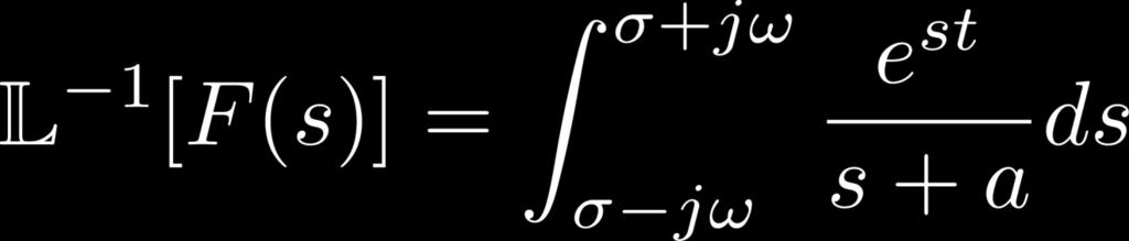
10 Example Let, compute Robo3x

11 Laplace Transform Tables Robo3x
12 Video 5.2 Vijay Kumar and Ani Hsieh Robo3x

13 Generalizing Given How do we obtain? Robo3x
 are Real & Repeated Case 3: Roots of D(s) are Complex or Imaginary Robo3x-1.1 14")
14 Partial Fraction Expansion Case 1: Roots of D(s) are Real & Distinct Case 2: Roots of D(s) are Real & Repeated Case 3: Roots of D(s) are Complex or Imaginary Robo3x
15 Case 1: Roots of D(s) are Real & Distinct Compute the Inverse Laplace of Robo3x

16 Case 2: Roots of D(s) are Real & Repeated Compute the Inverse Laplace of Robo3x

17 Case 3: Roots of D(s) are Complex Compute the Inverse Laplace of Robo3x
18 Video 5.3 Vijay Kumar and Ani Hsieh Robo3x
19 Using Laplace Transforms Given Solving for x(t) 1. Convert to frequency domain 2. Solve algebraic equation 3. Convert back to time domain Robo3x

20 Properties of Laplace Transforms Robo3x
21 Summary Laplace Transforms time domain <-> frequency domain differential equation <-> algebraic equation Partial Fraction Expansion factorizes complicated expressions to simplify computation of inverse Laplace Transforms Robo3x
22 Example: Solving an ODE (1) Given with, and. Solve for. Robo3x
23 Example: Solving an ODE (2) Robo3x
24 Video 5.4 Vijay Kumar and Ani Hsieh Robo3x
25 Controller Design Disturbance Input + - Input Controller + + Output Robo3x
26 Controller Design Disturbance Input Output Controller Robo3x
27 Controller Design Disturbance Input + - Controller + + System Output Robo3x

28 Controller Design Disturbance Input + - Controller + + System Output Robo3x
29 Transfer Function Relate a system s output to its input 1.Easy separation of INPUT, OUTPUT, SYSTEM (PLANT) 2.Algebraic relationships (vs. differential) 3.Easy interconnection of subsystems in a MATHEMATICAL framework Robo3x
30 In General A General N-Order Linear, Time Invariant ODE G(s) =Transfer Function = output/input Furthermore, if we know G(s), then output = G(s)*input Solution given by Robo3x

31 General Procedure Given performance criteria and desired 1. Convert 2. Analyze 3. Design using 4. Validate using 5. Iterate Robo3x
32 Underlying Assumptions Linearity 1. Superposition 2. Homogeneity System System B/c the Laplace Transform is Linear! Robo3x
33 Video 5.5 Vijay Kumar and Ani Hsieh Robo3x

34 Characterizing System Response Given How do we characterize the performance of a system? Special Case 1: 1 st Order Systems Special Case 2: 2 nd Order Systems Robo3x
35 Poles and Zeros Given Poles Zeros Example: Robo3x

 = 1/s,")

36 First Order Systems In general Let U(s) = 1/s, then As such, Therefore, Robo3x
37 Characterizing First Order Systems Given with U(s) = 1/s Robo3x

38 Characterizing First Order Systems Time Constant Rise Time Settling Time Robo3x
39 Second Order Systems Given, and U(s) = 1/s Possible Cases 1. r 1 & r 2 are real & distinct 2. r 1 & r 2 are real & repeated 3. r 1 & r 2 are both imaginary 4. r 1 & r 2 are complex conjugates Robo3x
40 Case 1: Real & Distinct Roots Overdamped response Robo3x
41 Video 5.6 Vijay Kumar and Ani Hsieh Robo3x

42 Case 2: Real & Repeated Roots Critically damped response Robo3x


43 Case 3: All Imaginary Roots Undamped response Robo3x
44 Case 4: Roots Are Complex Underdamped response Robo3x
45 A Closer Look at Case 4 Exponential Decay (Real Part) Sinusoidal Oscillations (Imaginary Part) Robo3x
46 Summary of 2 nd Order Systems Given, and U(s) = 1/s Solution is one of the following: 1. Overdamped: r 1 & r 2 are real & distinct 2. Critically Damped: r 1 & r 2 are real & repeated 3. Undamped: r 1 & r 2 are both imaginary 4. Underdamped: r 1 & r 2 are complex conjugates Robo3x
47 2 nd Order System Parameters Given and U(s) = 1/s Natural Frequency n System s frequency of oscillation with no damping Damping Ratio Robo3x


48 General 2 nd Order System Given and U(s) = 1/s When b = 0 For an underdamped system Robo3x
49 General 2 nd Order Systems Second-order system transfer functions have the form with poles of the form Example: For Compute, n, and s 1,2? Robo3x
50 Video 5.7 Vijay Kumar and Ani Hsieh Robo3x
51 Characterizing Underdamped Systems Robo3x
52 Peak Time Same Envelope Motion of poles Robo3x
53 Settling Time 2 1 Same Frequency 2 1 Motion of poles 2 1 Robo3x
54 Overshoot 3 Same Overshoot Motion of poles Robo3x
55 In Summary s-plane Robo3x
56 Video 5.8 Vijay Kumar and Ani Hsieh Robo3x
57 Independent Joint Control In general, n-link Robot Arm generally has n actuators Single Input Single Output (SISO) Single joint control Robo3x

58 Permanent Magnet DC Motor Picture Here Basic Principle Source: Wikimedia Commons Robo3x


59 Electrical Part Armature Current Back EMF Motor Torque Torque Constant Robo3x

60 Mechanical Part Gear ratio Actuator Dynamics Robo3x

61 Combining the Two Correction: the K b terms should be K m Robo3x
62 Two SISO Outcomes Input Voltage Motor Shaft Position Load Torque Motor Shaft Position Robo3x
63 Video 5.9 Vijay Kumar and Ani Hsieh Robo3x
64 Two SISO Outcomes Input Voltage Motor Shaft Position Load Torque Motor Shaft Position Assumption: L/R << J m /B m Robo3x

65 2 nd Order Approximation Divide by R and set L/R = 0 In the time domain Robo3x
66 Open-Loop System Actuator Dynamics Set-point tracking (feedback) Trajectory tracking (feedforward) Robo3x
67 Our Control Objectives Motion sequence of end-effector positions and orientations (EE poses) EE poses Joint Angles Motor Commands Transfer function Three primary linear controller designs: P (proportional) PD (proportional-derivative) PID (proportional-integral-derivative) Robo3x
68 Set-Point Tracking The Basic PID Controller Robo3x
69 Proportional (P) Control Control input proportional to error K P controller gain Error is amplified by K P to obtain the desired output signal Robo3x


70 P Control of Vehicle Speed Example: Cruise Control X v Desired linear speed q Y vehicle wheel speed Control input proportional to error Robo3x
71 Performance of P Controller K P = 10 K P = 50 K P = 100 Increases the controller gain decreases rise time Excessive gain can result in overshoot Robo3x
72 Video 5.10 Vijay Kumar and Ani Hsieh Robo3x
73 Proportional-Derivative (PD) Control Control input proportional to error AND 1 st derivative of error Including rate of change of error helps mitigates oscillations Robo3x
74 Performance of PD Controller K P = 10 K D = 1 K P = 10 K D = 3 Decreases rise time K P = 500 K D = 10 K P = 500 K D = 50 Reduces overshoot & Settling Time Robo3x

75 PD Control of a Joint Closed loop system given by w/ Robo3x
76 PD Compensated Closed Loop Response (1) Robo3x
 Robo3x-1.1 77")
77 PD Compensated Closed Loop Response (2) Robo3x
78 Picking K P and K D Closed loop system w/ Design Guidelines Critically damped w/ Pick and Robo3x


79 Performance of the PD Controller Assuming and Tracking error is given by At steady-state Robo3x
80 Video 5.11 Vijay Kumar and Ani Hsieh Robo3x
81 Proportional-Integral-Derivative (PID) Controller Control input proportional to error, 1 st derivative AND an integral of the error The integral term offsets any steady-state errors in the system Robo3x
82 Performance of PID Controller K P = 10 K D = 3 K P = 10 K D = 3 K I = 1 K P = 10 K D = 3 K I = 50 Eliminates SS-Error Increases overshoot & settling time Robo3x
83 PID Control of a Joint Closed-loop system is given by w/ Robo3x
84 PID Compensated Closed Loop Response (1) Robo3x
85 PID Compensated Closed Loop Response (2) Robo3x

86 Picking K P, K D, and K I Closed loop system w/ Design Guidelines System stable if K P, K D, and K I >0 Set K I = 0 and pick K P, K D, then go back to pick K I w/ in mind Robo3x
87 Summary of PID Characteristics CL Response Rise Time % Overshoot K P Decrease Increase K D Small Change Decrease Settling Time Small Change Decrease S-S Error Decrease Small Change K I Decrease Increase Increase Eliminate Robo3x
88 Tuning Gains Appropriate gain selection is crucial for optimal controller performance Analytically (R-Locus, Frequency Design, Ziegler Nichols, etc) Empirically The case for experimental validation Model fidelity Optimize for specific hardware Saturation and flexibility Robo3x

 What if instead of, we")
89 Feedforward Control Motion sequence of end-effector positions and orientations (EE poses) What if instead of, we want? Robo3x
90 Video 5.12 Vijay Kumar and Ani Hsieh Robo3x


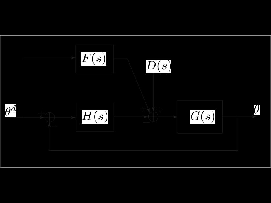
91 Closed Loop Transfer Function (1) Robo3x
92 Closed Loop Transfer Function (2) Robo3x
93 Closed Loop Transfer Function (3) Robo3x
94 Picking F(s) Closed loop transfer function given by Behavior of closed loop response, given by roots of H(s) and F(s) be chosen so that Robo3x
 = 1/G(s), i.e.")
95 Will This Work? Let F(s) = 1/G(s), i.e., a(s) = p(s) and b(s) = q(s), then System will track any reference trajectory! Robo3x
96 Caveats Minimum Phase Systems Picking F(s) = 1/G(s), leads to Assume system w/o FF loop is stable By picking F(s) = 1/G(s), we require numerator of G(s) to be Hurwitz (or ) Systems whose numerators have roots with negative real parts are called Minimum Phase Robo3x
 = 1/G(s) = Note the following:")
97 Feedforward Control w/ Disturbance Assume: D(s) = constant w/ Pick F(s) = 1/G(s) = Note the following: Robo3x
98 Tracking Error Control law in time domain System dynamics w/ control + disturbance Robo3x
99 Overall Performance Robo3x
Video 6.1 Vijay Kumar and Ani Hsieh
 Video 6.1 Vijay Kumar and Ani Hsieh Robo3x-1.6 1 In General Disturbance Input + - Input Controller + + System Output Robo3x-1.6 2 Learning Objectives for this Week State Space Notation Modeling in the
Index. Index. More information. in this web service Cambridge University Press
 A-type elements, 4 7, 18, 31, 168, 198, 202, 219, 220, 222, 225 A-type variables. See Across variable ac current, 172, 251 ac induction motor, 251 Acceleration rotational, 30 translational, 16 Accumulator,
Feedback Control of Linear SISO systems. Process Dynamics and Control
 Feedback Control of Linear SISO systems Process Dynamics and Control 1 Open-Loop Process The study of dynamics was limited to open-loop systems Observe process behavior as a result of specific input signals
Positioning Servo Design Example
 Positioning Servo Design Example 1 Goal. The goal in this design example is to design a control system that will be used in a pick-and-place robot to move the link of a robot between two positions. Usually
CHAPTER 5 : REDUCTION OF MULTIPLE SUBSYSTEMS
 CHAPTER 5 : REDUCTION OF MULTIPLE SUBSYSTEMS Objectives Students should be able to: Reduce a block diagram of multiple subsystems to a single block representing the transfer function from input to output
(a) Torsional spring-mass system. (b) Spring element.
 Torsional spring-mass system. (b) Spring element.") m v s T s v a (a) T a (b) T a FIGURE 2.1 (a) Torsional spring-mass system. (b) Spring element. by ky Wall friction, b Mass M k y M y r(t) Force r(t) (a) (b) FIGURE 2.2 (a) Spring-mass-damper system. (b)
m v s T s v a (a) T a (b) T a FIGURE 2.1 (a) Torsional spring-mass system. (b) Spring element. by ky Wall friction, b Mass M k y M y r(t) Force r(t) (a) (b) FIGURE 2.2 (a) Spring-mass-damper system. (b)
Poles, Zeros and System Response
 Time Response After the engineer obtains a mathematical representation of a subsystem, the subsystem is analyzed for its transient and steady state responses to see if these characteristics yield the desired
Control of Manufacturing Processes
 Control of Manufacturing Processes Subject 2.830 Spring 2004 Lecture #19 Position Control and Root Locus Analysis" April 22, 2004 The Position Servo Problem, reference position NC Control Robots Injection
DC Motor Position: System Modeling
 1 of 7 01/03/2014 22:07 Tips Effects TIPS ABOUT BASICS INDEX NEXT INTRODUCTION CRUISE CONTROL MOTOR SPEED MOTOR POSITION SUSPENSION INVERTED PENDULUM SYSTEM MODELING ANALYSIS DC Motor Position: System
Course Summary. The course cannot be summarized in one lecture.
 Course Summary Unit 1: Introduction Unit 2: Modeling in the Frequency Domain Unit 3: Time Response Unit 4: Block Diagram Reduction Unit 5: Stability Unit 6: Steady-State Error Unit 7: Root Locus Techniques
Time Response Analysis (Part II)
") Time Response Analysis (Part II). A critically damped, continuous-time, second order system, when sampled, will have (in Z domain) (a) A simple pole (b) Double pole on real axis (c) Double pole on imaginary
Time Response Analysis (Part II). A critically damped, continuous-time, second order system, when sampled, will have (in Z domain) (a) A simple pole (b) Double pole on real axis (c) Double pole on imaginary
(b) A unity feedback system is characterized by the transfer function. Design a suitable compensator to meet the following specifications:
 A unity feedback system is characterized by the transfer function. Design a suitable compensator to meet the following specifications:") 1. (a) The open loop transfer function of a unity feedback control system is given by G(S) = K/S(1+0.1S)(1+S) (i) Determine the value of K so that the resonance peak M r of the system is equal to 1.4.
1. (a) The open loop transfer function of a unity feedback control system is given by G(S) = K/S(1+0.1S)(1+S) (i) Determine the value of K so that the resonance peak M r of the system is equal to 1.4.
R a) Compare open loop and closed loop control systems. b) Clearly bring out, from basics, Force-current and Force-Voltage analogies.
 Compare open loop and closed loop control systems. b) Clearly bring out, from basics, Force-current and Force-Voltage analogies.") SET - 1 II B. Tech II Semester Supplementary Examinations Dec 01 1. a) Compare open loop and closed loop control systems. b) Clearly bring out, from basics, Force-current and Force-Voltage analogies..
SET - 1 II B. Tech II Semester Supplementary Examinations Dec 01 1. a) Compare open loop and closed loop control systems. b) Clearly bring out, from basics, Force-current and Force-Voltage analogies..
Manufacturing Equipment Control
 QUESTION 1 An electric drive spindle has the following parameters: J m = 2 1 3 kg m 2, R a = 8 Ω, K t =.5 N m/a, K v =.5 V/(rad/s), K a = 2, J s = 4 1 2 kg m 2, and K s =.3. Ignore electrical dynamics
Course roadmap. Step response for 2nd-order system. Step response for 2nd-order system
 ME45: Control Systems Lecture Time response of nd-order systems Prof. Clar Radcliffe and Prof. Jongeun Choi Department of Mechanical Engineering Michigan State University Modeling Laplace transform Transfer
Control of Manufacturing Processes
 Control of Manufacturing Processes Subject 2.830 Spring 2004 Lecture #18 Basic Control Loop Analysis" April 15, 2004 Revisit Temperature Control Problem τ dy dt + y = u τ = time constant = gain y ss =
Table of Laplacetransform
 Appendix Table of Laplacetransform pairs 1(t) f(s) oct), unit impulse at t = 0 a, a constant or step of magnitude a at t = 0 a s t, a ramp function e- at, an exponential function s + a sin wt, a sine fun
Lecture 25: Tue Nov 27, 2018
 Lecture 25: Tue Nov 27, 2018 Reminder: Lab 3 moved to Tuesday Dec 4 Lecture: review time-domain characteristics of 2nd-order systems intro to control: feedback open-loop vs closed-loop control intro to
Laboratory 11 Control Systems Laboratory ECE3557. State Feedback Controller for Position Control of a Flexible Joint
 Laboratory 11 State Feedback Controller for Position Control of a Flexible Joint 11.1 Objective The objective of this laboratory is to design a full state feedback controller for endpoint position control
Position Control Experiment MAE171a
 Position Control Experiment MAE171a January 11, 014 Prof. R.A. de Callafon, Dept. of MAE, UCSD TAs: Jeff Narkis, email: jnarkis@ucsd.edu Gil Collins, email: gwcollin@ucsd.edu Contents 1 Aim and Procedure
D(s) G(s) A control system design definition
 G(s) A control system design definition") R E Compensation D(s) U Plant G(s) Y Figure 7. A control system design definition x x x 2 x 2 U 2 s s 7 2 Y Figure 7.2 A block diagram representing Eq. (7.) in control form z U 2 s z Y 4 z 2 s z 2 3 Figure
R E Compensation D(s) U Plant G(s) Y Figure 7. A control system design definition x x x 2 x 2 U 2 s s 7 2 Y Figure 7.2 A block diagram representing Eq. (7.) in control form z U 2 s z Y 4 z 2 s z 2 3 Figure
Analysis and Design of Control Systems in the Time Domain
 Chapter 6 Analysis and Design of Control Systems in the Time Domain 6. Concepts of feedback control Given a system, we can classify it as an open loop or a closed loop depends on the usage of the feedback.
Transient Response of a Second-Order System
 Transient Response of a Second-Order System ECEN 830 Spring 01 1. Introduction In connection with this experiment, you are selecting the gains in your feedback loop to obtain a well-behaved closed-loop
Example: Modeling DC Motor Position Physical Setup System Equations Design Requirements MATLAB Representation and Open-Loop Response
 Page 1 of 5 Example: Modeling DC Motor Position Physical Setup System Equations Design Requirements MATLAB Representation and Open-Loop Response Physical Setup A common actuator in control systems is the
Performance of Feedback Control Systems
 Performance of Feedback Control Systems Design of a PID Controller Transient Response of a Closed Loop System Damping Coefficient, Natural frequency, Settling time and Steady-state Error and Type 0, Type
Dr Ian R. Manchester Dr Ian R. Manchester AMME 3500 : Review
 Week Date Content Notes 1 6 Mar Introduction 2 13 Mar Frequency Domain Modelling 3 20 Mar Transient Performance and the s-plane 4 27 Mar Block Diagrams Assign 1 Due 5 3 Apr Feedback System Characteristics
Autonomous Mobile Robot Design
 Autonomous Mobile Robot Design Topic: Guidance and Control Introduction and PID Loops Dr. Kostas Alexis (CSE) Autonomous Robot Challenges How do I control where to go? Autonomous Mobile Robot Design Topic:
CHAPTER 1 Basic Concepts of Control System. CHAPTER 6 Hydraulic Control System
 CHAPTER 1 Basic Concepts of Control System 1. What is open loop control systems and closed loop control systems? Compare open loop control system with closed loop control system. Write down major advantages
C(s) R(s) 1 C(s) C(s) C(s) = s - T. Ts + 1 = 1 s - 1. s + (1 T) Taking the inverse Laplace transform of Equation (5 2), we obtain
 R(s) 1 C(s) C(s) C(s) = s - T. Ts + 1 = 1 s - 1. s + (1 T) Taking the inverse Laplace transform of Equation (5 2), we obtain") analyses of the step response, ramp response, and impulse response of the second-order systems are presented. Section 5 4 discusses the transient-response analysis of higherorder systems. Section 5 5 gives
analyses of the step response, ramp response, and impulse response of the second-order systems are presented. Section 5 4 discusses the transient-response analysis of higherorder systems. Section 5 5 gives
2.004 Dynamics and Control II Spring 2008
 MIT OpenCourseWare http://ocw.mit.edu 2.004 Dynamics and Control II Spring 2008 For information about citing these materials or our Terms of Use, visit: http://ocw.mit.edu/terms. Massachusetts Institute
FEEDBACK CONTROL SYSTEMS
 FEEDBAC CONTROL SYSTEMS. Control System Design. Open and Closed-Loop Control Systems 3. Why Closed-Loop Control? 4. Case Study --- Speed Control of a DC Motor 5. Steady-State Errors in Unity Feedback Control
Controls Problems for Qualifying Exam - Spring 2014
 Controls Problems for Qualifying Exam - Spring 2014 Problem 1 Consider the system block diagram given in Figure 1. Find the overall transfer function T(s) = C(s)/R(s). Note that this transfer function
Control Systems. University Questions
 University Questions UNIT-1 1. Distinguish between open loop and closed loop control system. Describe two examples for each. (10 Marks), Jan 2009, June 12, Dec 11,July 08, July 2009, Dec 2010 2. Write
Linear State Feedback Controller Design
 Assignment For EE5101 - Linear Systems Sem I AY2010/2011 Linear State Feedback Controller Design Phang Swee King A0033585A Email: king@nus.edu.sg NGS/ECE Dept. Faculty of Engineering National University
1 An Overview and Brief History of Feedback Control 1. 2 Dynamic Models 23. Contents. Preface. xiii
 Contents 1 An Overview and Brief History of Feedback Control 1 A Perspective on Feedback Control 1 Chapter Overview 2 1.1 A Simple Feedback System 3 1.2 A First Analysis of Feedback 6 1.3 Feedback System
Chapter 7 Control. Part Classical Control. Mobile Robotics - Prof Alonzo Kelly, CMU RI
 Chapter 7 Control 7.1 Classical Control Part 1 1 7.1 Classical Control Outline 7.1.1 Introduction 7.1.2 Virtual Spring Damper 7.1.3 Feedback Control 7.1.4 Model Referenced and Feedforward Control Summary
EE3CL4: Introduction to Linear Control Systems
 1 / 17 EE3CL4: Introduction to Linear Control Systems Section 7: McMaster University Winter 2018 2 / 17 Outline 1 4 / 17 Cascade compensation Throughout this lecture we consider the case of H(s) = 1. We
ECSE 4962 Control Systems Design. A Brief Tutorial on Control Design
 ECSE 4962 Control Systems Design A Brief Tutorial on Control Design Instructor: Professor John T. Wen TA: Ben Potsaid http://www.cat.rpi.edu/~wen/ecse4962s04/ Don t Wait Until The Last Minute! You got
CYBER EXPLORATION LABORATORY EXPERIMENTS
 CYBER EXPLORATION LABORATORY EXPERIMENTS 1 2 Cyber Exploration oratory Experiments Chapter 2 Experiment 1 Objectives To learn to use MATLAB to: (1) generate polynomial, (2) manipulate polynomials, (3)
KINGS COLLEGE OF ENGINEERING DEPARTMENT OF ELECTRONICS AND COMMUNICATION ENGINEERING
 KINGS COLLEGE OF ENGINEERING DEPARTMENT OF ELECTRONICS AND COMMUNICATION ENGINEERING QUESTION BANK SUB.NAME : CONTROL SYSTEMS BRANCH : ECE YEAR : II SEMESTER: IV 1. What is control system? 2. Define open
Answers to multiple choice questions
 Answers to multiple choice questions Chapter 2 M2.1 (b) M2.2 (a) M2.3 (d) M2.4 (b) M2.5 (a) M2.6 (b) M2.7 (b) M2.8 (c) M2.9 (a) M2.10 (b) Chapter 3 M3.1 (b) M3.2 (d) M3.3 (d) M3.4 (d) M3.5 (c) M3.6 (c)
SRV02-Series Rotary Experiment # 1. Position Control. Student Handout
 SRV02-Series Rotary Experiment # 1 Position Control Student Handout SRV02-Series Rotary Experiment # 1 Position Control Student Handout 1. Objectives The objective in this experiment is to introduce the
An Introduction to Control Systems
 An Introduction to Control Systems Signals and Systems: 3C1 Control Systems Handout 1 Dr. David Corrigan Electronic and Electrical Engineering corrigad@tcd.ie November 21, 2012 Recall the concept of a
Lecture 12. Upcoming labs: Final Exam on 12/21/2015 (Monday)10:30-12:30
10:30-12:30") 289 Upcoming labs: Lecture 12 Lab 20: Internal model control (finish up) Lab 22: Force or Torque control experiments [Integrative] (2-3 sessions) Final Exam on 12/21/2015 (Monday)10:30-12:30 Today: Recap
289 Upcoming labs: Lecture 12 Lab 20: Internal model control (finish up) Lab 22: Force or Torque control experiments [Integrative] (2-3 sessions) Final Exam on 12/21/2015 (Monday)10:30-12:30 Today: Recap
Example: DC Motor Speed Modeling
 Page 1 of 5 Example: DC Motor Speed Modeling Physical setup and system equations Design requirements MATLAB representation and open-loop response Physical setup and system equations A common actuator in
BASIC PROPERTIES OF FEEDBACK
 ECE450/550: Feedback Control Systems. 4 BASIC PROPERTIES OF FEEDBACK 4.: Setting up an example to benchmark controllers There are two basic types/categories of control systems: OPEN LOOP: Disturbance r(t)
(a) Torsional spring-mass system. (b) Spring element.
 Torsional spring-mass system. (b) Spring element.") m v s T s v a (a) T a (b) T a FIGURE 2.1 (a) Torsional spring-mass system. (b) Spring element. by ky Wall friction, b Mass M k y M y r(t) Force r(t) (a) (b) FIGURE 2.2 (a) Spring-mass-damper system. (b)
m v s T s v a (a) T a (b) T a FIGURE 2.1 (a) Torsional spring-mass system. (b) Spring element. by ky Wall friction, b Mass M k y M y r(t) Force r(t) (a) (b) FIGURE 2.2 (a) Spring-mass-damper system. (b)
Alireza Mousavi Brunel University
 Alireza Mousavi Brunel University 1 » Control Process» Control Systems Design & Analysis 2 Open-Loop Control: Is normally a simple switch on and switch off process, for example a light in a room is switched
Laboratory Exercise 1 DC servo
 Laboratory Exercise DC servo Per-Olof Källén ø 0,8 POWER SAT. OVL.RESET POS.RESET Moment Reference ø 0,5 ø 0,5 ø 0,5 ø 0,65 ø 0,65 Int ø 0,8 ø 0,8 Σ k Js + d ø 0,8 s ø 0 8 Off Off ø 0,8 Ext. Int. + x0,
Quanser NI-ELVIS Trainer (QNET) Series: QNET Experiment #02: DC Motor Position Control. DC Motor Control Trainer (DCMCT) Student Manual
 Series: QNET Experiment #02: DC Motor Position Control. DC Motor Control Trainer (DCMCT) Student Manual") Quanser NI-ELVIS Trainer (QNET) Series: QNET Experiment #02: DC Motor Position Control DC Motor Control Trainer (DCMCT) Student Manual Table of Contents 1 Laboratory Objectives1 2 References1 3 DCMCT Plant
Quanser NI-ELVIS Trainer (QNET) Series: QNET Experiment #02: DC Motor Position Control DC Motor Control Trainer (DCMCT) Student Manual Table of Contents 1 Laboratory Objectives1 2 References1 3 DCMCT Plant
Introduction to Feedback Control
 Introduction to Feedback Control Control System Design Why Control? Open-Loop vs Closed-Loop (Feedback) Why Use Feedback Control? Closed-Loop Control System Structure Elements of a Feedback Control System
APPLICATIONS FOR ROBOTICS
 Version: 1 CONTROL APPLICATIONS FOR ROBOTICS TEX d: Feb. 17, 214 PREVIEW We show that the transfer function and conditions of stability for linear systems can be studied using Laplace transforms. Table
7.4 STEP BY STEP PROCEDURE TO DRAW THE ROOT LOCUS DIAGRAM
 ROOT LOCUS TECHNIQUE. Values of on the root loci The value of at any point s on the root loci is determined from the following equation G( s) H( s) Product of lengths of vectors from poles of G( s)h( s)
6.1 Sketch the z-domain root locus and find the critical gain for the following systems K., the closed-loop characteristic equation is K + z 0.
 6. Sketch the z-domain root locus and find the critical gain for the following systems K (i) Gz () z 4. (ii) Gz K () ( z+ 9. )( z 9. ) (iii) Gz () Kz ( z. )( z ) (iv) Gz () Kz ( + 9. ) ( z. )( z 8. ) (i)
Feedback Control Systems
 ME Homework #0 Feedback Control Systems Last Updated November 06 Text problem 67 (Revised Chapter 6 Homework Problems- attached) 65 Chapter 6 Homework Problems 65 Transient Response of a Second Order Model
Analysis and Synthesis of Single-Input Single-Output Control Systems
 Lino Guzzella Analysis and Synthesis of Single-Input Single-Output Control Systems l+kja» \Uja>)W2(ja»\ um Contents 1 Definitions and Problem Formulations 1 1.1 Introduction 1 1.2 Definitions 1 1.2.1 Systems
Outline. Classical Control. Lecture 5
 Outline Outline Outline 1 What is 2 Outline What is Why use? Sketching a 1 What is Why use? Sketching a 2 Gain Controller Lead Compensation Lag Compensation What is Properties of a General System Why use?
06 Feedback Control System Characteristics The role of error signals to characterize feedback control system performance.
 Chapter 06 Feedback 06 Feedback Control System Characteristics The role of error signals to characterize feedback control system performance. Lesson of the Course Fondamenti di Controlli Automatici of
Professional Portfolio Selection Techniques: From Markowitz to Innovative Engineering
 Massachusetts Institute of Technology Sponsor: Electrical Engineering and Computer Science Cosponsor: Science Engineering and Business Club Professional Portfolio Selection Techniques: From Markowitz to
EE 3CL4: Introduction to Control Systems Lab 4: Lead Compensation
 EE 3CL4: Introduction to Control Systems Lab 4: Lead Compensation Tim Davidson Ext. 27352 davidson@mcmaster.ca Objective To use the root locus technique to design a lead compensator for a marginally-stable
Review: stability; Routh Hurwitz criterion Today s topic: basic properties and benefits of feedback control
 Plan of the Lecture Review: stability; Routh Hurwitz criterion Today s topic: basic properties and benefits of feedback control Goal: understand the difference between open-loop and closed-loop (feedback)
Plan of the Lecture. Review: stability; Routh Hurwitz criterion Today s topic: basic properties and benefits of feedback control
 Plan of the Lecture Review: stability; Routh Hurwitz criterion Today s topic: basic properties and benefits of feedback control Plan of the Lecture Review: stability; Routh Hurwitz criterion Today s topic:
SECTION 2: BLOCK DIAGRAMS & SIGNAL FLOW GRAPHS
 SECTION 2: BLOCK DIAGRAMS & SIGNAL FLOW GRAPHS MAE 4421 Control of Aerospace & Mechanical Systems 2 Block Diagram Manipulation Block Diagrams 3 In the introductory section we saw examples of block diagrams
Topic # Feedback Control Systems
 Topic #1 16.31 Feedback Control Systems Motivation Basic Linear System Response Fall 2007 16.31 1 1 16.31: Introduction r(t) e(t) d(t) y(t) G c (s) G(s) u(t) Goal: Design a controller G c (s) so that the
Control Systems! Copyright 2017 by Robert Stengel. All rights reserved. For educational use only.
 Control Systems Robert Stengel Robotics and Intelligent Systems MAE 345, Princeton University, 2017 Analog vs. digital systems Continuous- and Discretetime Dynamic Models Frequency Response Transfer Functions
Contents. PART I METHODS AND CONCEPTS 2. Transfer Function Approach Frequency Domain Representations... 42
 Contents Preface.............................................. xiii 1. Introduction......................................... 1 1.1 Continuous and Discrete Control Systems................. 4 1.2 Open-Loop
Predictive Cascade Control of DC Motor
 Volume 49, Number, 008 89 Predictive Cascade Control of DC Motor Alexandru MORAR Abstract: The paper deals with the predictive cascade control of an electrical drive intended for positioning applications.
ECE317 : Feedback and Control
 ECE317 : Feedback and Control Lecture : Steady-state error Dr. Richard Tymerski Dept. of Electrical and Computer Engineering Portland State University 1 Course roadmap Modeling Analysis Design Laplace
UNIVERSITY OF WASHINGTON Department of Aeronautics and Astronautics
 UNIVERSITY OF WASHINGTON Department of Aeronautics and Astronautics Modeling and Control of a Flexishaft System March 19, 2003 Christopher Lum Travis Reisner Amanda Stephens Brian Hass AA/EE-448 Controls
Overview of the Seminar Topic
 Overview of the Seminar Topic Simo Särkkä Laboratory of Computational Engineering Helsinki University of Technology September 17, 2007 Contents 1 What is Control Theory? 2 History
School of Mechanical Engineering Purdue University. ME375 Feedback Control - 1
 Introduction to Feedback Control Control System Design Why Control? Open-Loop vs Closed-Loop (Feedback) Why Use Feedback Control? Closed-Loop Control System Structure Elements of a Feedback Control System
Second Order and Higher Order Systems
 Second Order and Higher Order Systems 1. Second Order System In this section, we shall obtain the response of a typical second-order control system to a step input. In terms of damping ratio and natural
Dr Ian R. Manchester
 Week Content Notes 1 Introduction 2 Frequency Domain Modelling 3 Transient Performance and the s-plane 4 Block Diagrams 5 Feedback System Characteristics Assign 1 Due 6 Root Locus 7 Root Locus 2 Assign
Dynamic Compensation using root locus method
 CAIRO UNIVERSITY FACULTY OF ENGINEERING ELECTRONICS & COMMUNICATIONS DEP. 3rd YEAR, 00/0 CONTROL ENGINEERING SHEET 9 Dynamic Compensation using root locus method [] (Final00)For the system shown in the
MAE143a: Signals & Systems (& Control) Final Exam (2011) solutions
 Final Exam (2011) solutions") MAE143a: Signals & Systems (& Control) Final Exam (2011) solutions Question 1. SIGNALS: Design of a noise-cancelling headphone system. 1a. Based on the low-pass filter given, design a high-pass filter,
MAE143a: Signals & Systems (& Control) Final Exam (2011) solutions Question 1. SIGNALS: Design of a noise-cancelling headphone system. 1a. Based on the low-pass filter given, design a high-pass filter,
DC-motor PID control
 DC-motor PID control This version: November 1, 2017 REGLERTEKNIK Name: P-number: AUTOMATIC LINKÖPING CONTROL Date: Passed: Chapter 1 Introduction The purpose of this lab is to give an introduction to
General procedure for formulation of robot dynamics STEP 1 STEP 3. Module 9 : Robot Dynamics & controls
 Module 9 : Robot Dynamics & controls Lecture 32 : General procedure for dynamics equation forming and introduction to control Objectives In this course you will learn the following Lagrangian Formulation
CHBE320 LECTURE XI CONTROLLER DESIGN AND PID CONTOLLER TUNING. Professor Dae Ryook Yang
 CHBE320 LECTURE XI CONTROLLER DESIGN AND PID CONTOLLER TUNING Professor Dae Ryook Yang Spring 2018 Dept. of Chemical and Biological Engineering 11-1 Road Map of the Lecture XI Controller Design and PID
Lecture 5 Classical Control Overview III. Dr. Radhakant Padhi Asst. Professor Dept. of Aerospace Engineering Indian Institute of Science - Bangalore
 Lecture 5 Classical Control Overview III Dr. Radhakant Padhi Asst. Professor Dept. of Aerospace Engineering Indian Institute of Science - Bangalore A Fundamental Problem in Control Systems Poles of open
MEM 355 Performance Enhancement of Dynamical Systems
 MEM 355 Performance Enhancement of Dynamical Systems Frequency Domain Design Intro Harry G. Kwatny Department of Mechanical Engineering & Mechanics Drexel University /5/27 Outline Closed Loop Transfer
Part IB Paper 6: Information Engineering LINEAR SYSTEMS AND CONTROL. Glenn Vinnicombe HANDOUT 5. An Introduction to Feedback Control Systems
 Part IB Paper 6: Information Engineering LINEAR SYSTEMS AND CONTROL Glenn Vinnicombe HANDOUT 5 An Introduction to Feedback Control Systems ē(s) ȳ(s) Σ K(s) G(s) z(s) H(s) z(s) = H(s)G(s)K(s) L(s) ē(s)=
Radar Dish. Armature controlled dc motor. Inside. θ r input. Outside. θ D output. θ m. Gearbox. Control Transmitter. Control. θ D.
 Radar Dish ME 304 CONTROL SYSTEMS Mechanical Engineering Department, Middle East Technical University Armature controlled dc motor Outside θ D output Inside θ r input r θ m Gearbox Control Transmitter
Appendix A: Exercise Problems on Classical Feedback Control Theory (Chaps. 1 and 2)
") Appendix A: Exercise Problems on Classical Feedback Control Theory (Chaps. 1 and 2) For all calculations in this book, you can use the MathCad software or any other mathematical software that you are familiar
Appendix A: Exercise Problems on Classical Feedback Control Theory (Chaps. 1 and 2) For all calculations in this book, you can use the MathCad software or any other mathematical software that you are familiar
AN INTRODUCTION TO THE CONTROL THEORY
 Open-Loop controller An Open-Loop (OL) controller is characterized by no direct connection between the output of the system and its input; therefore external disturbance, non-linear dynamics and parameter
Systems Analysis and Control
 Systems Analysis and Control Matthew M. Peet Illinois Institute of Technology Lecture 8: Response Characteristics Overview In this Lecture, you will learn: Characteristics of the Response Stability Real
DOUBLE ARM JUGGLING SYSTEM Progress Presentation ECSE-4962 Control Systems Design
 DOUBLE ARM JUGGLING SYSTEM Progress Presentation ECSE-4962 Control Systems Design Group Members: John Kua Trinell Ball Linda Rivera Introduction Where are we? Bulk of Design and Build Complete Testing
EE 422G - Signals and Systems Laboratory
 EE 4G - Signals and Systems Laboratory Lab 9 PID Control Kevin D. Donohue Department of Electrical and Computer Engineering University of Kentucky Lexington, KY 40506 April, 04 Objectives: Identify the
Systems Analysis and Control
 Systems Analysis and Control Matthew M. Peet Arizona State University Lecture 8: Response Characteristics Overview In this Lecture, you will learn: Characteristics of the Response Stability Real Poles
Control System Design
 ELEC4410 Control System Design Lecture 19: Feedback from Estimated States and Discrete-Time Control Design Julio H. Braslavsky julio@ee.newcastle.edu.au School of Electrical Engineering and Computer Science
Root Locus. Motivation Sketching Root Locus Examples. School of Mechanical Engineering Purdue University. ME375 Root Locus - 1
 Root Locus Motivation Sketching Root Locus Examples ME375 Root Locus - 1 Servo Table Example DC Motor Position Control The block diagram for position control of the servo table is given by: D 0.09 Position
Robot Manipulator Control. Hesheng Wang Dept. of Automation
 Robot Manipulator Control Hesheng Wang Dept. of Automation Introduction Industrial robots work based on the teaching/playback scheme Operators teach the task procedure to a robot he robot plays back eecute
School of Mechanical Engineering Purdue University. ME375 ElectroMechanical - 1
 Electro-Mechanical Systems DC Motors Principles of Operation Modeling (Derivation of fg Governing Equations (EOM)) Block Diagram Representations Using Block Diagrams to Represent Equations in s - Domain
Lab 3: Model based Position Control of a Cart
 I. Objective Lab 3: Model based Position Control of a Cart The goal of this lab is to help understand the methodology to design a controller using the given plant dynamics. Specifically, we would do position
R10 JNTUWORLD B 1 M 1 K 2 M 2. f(t) Figure 1
 Figure 1") Code No: R06 R0 SET - II B. Tech II Semester Regular Examinations April/May 03 CONTROL SYSTEMS (Com. to EEE, ECE, EIE, ECC, AE) Time: 3 hours Max. Marks: 75 Answer any FIVE Questions All Questions carry
Code No: R06 R0 SET - II B. Tech II Semester Regular Examinations April/May 03 CONTROL SYSTEMS (Com. to EEE, ECE, EIE, ECC, AE) Time: 3 hours Max. Marks: 75 Answer any FIVE Questions All Questions carry
Mechatronics Engineering. Li Wen
 Mechatronics Engineering Li Wen Bio-inspired robot-dc motor drive Unstable system Mirko Kovac,EPFL Modeling and simulation of the control system Problems 1. Why we establish mathematical model of the control
System Modeling: Motor position, θ The physical parameters for the dc motor are:
 Dept. of EEE, KUET, Sessional on EE 3202: Expt. # 2 2k15 Batch Experiment No. 02 Name of the experiment: Modeling of Physical systems and study of their closed loop response Objective: (i) (ii) (iii) (iv)
State Feedback Controller for Position Control of a Flexible Link
 Laboratory 12 Control Systems Laboratory ECE3557 Laboratory 12 State Feedback Controller for Position Control of a Flexible Link 12.1 Objective The objective of this laboratory is to design a full state
Video 8.1 Vijay Kumar. Property of University of Pennsylvania, Vijay Kumar
 Video 8.1 Vijay Kumar 1 Definitions State State equations Equilibrium 2 Stability Stable Unstable Neutrally (Critically) Stable 3 Stability Translate the origin to x e x(t) =0 is stable (Lyapunov stable)
CHAPTER 7 STEADY-STATE RESPONSE ANALYSES
 CHAPTER 7 STEADY-STATE RESPONSE ANALYSES 1. Introduction The steady state error is a measure of system accuracy. These errors arise from the nature of the inputs, system type and from nonlinearities of
Controller Design using Root Locus
 Chapter 4 Controller Design using Root Locus 4. PD Control Root locus is a useful tool to design different types of controllers. Below, we will illustrate the design of proportional derivative controllers