Bedrock Dewatering for Construction of Marmet and Soo Lock Projects
|
|
|
- Daniella French
- 5 years ago
- Views:
Transcription


1 Bedrock Dewatering for Construction of Marmet and Soo Lock Projects Michael Nield Engineering Geologist Dam Safety Production Center, Huntington, WV August 2012 US Army Corps of Engineers
 - Project Description - Site Geology - Permeability and Groundwater Inflow - Dewatering Provisions 2.")
2 BEDROCK DEWATERING FOR CONSTRUCTION OUTLINE 1. Marmet Lock Replacement Project (construction) - Project Description - Site Geology - Permeability and Groundwater Inflow - Dewatering Provisions 2. Soo Lock Replacement Project (design) - Project Description - Site Geology - Permeability and Predicted Groundwater Inflow - Impact to Design

3 MARMET LOCK - PROJECT DESCRIPTION OHIIO RIVER GREAT LAKES DIVISION Located on Kanawha River, near Charleston, West Virginia. MARMET LOCKS & DAM Permits economic river transportation of coal, aggregate and chemicals. Construction of the new replacement lock was completed in 2009

4 Busiest Lock in USA Prior to New Lock Twin 56 X 360 Chambers Completed in 1934 Aerial View Original Locks

5 New 110 X 800 Lock Chamber Original Locks New Guard Wall New Guide Walls Aerial View New Replacement Lock

6 MARMET LOCK - SITE GEOLOGY 157 TOTAL BORINGS 10,200 TOTAL DRILLING 3,700 ROCK CORE 294 PRESSURE TESTS Subsurface Exploration Boring Location Plan BUILDING STRONG
7 General Geology Soil thickness 40 to 60 feet Relatively flat top of rock surface at elev. 552 ± 3 Sedimentary rock of the Pennsylvanian-aged Kanawha Formation Sandstone member (23 to 43 feet thick) Shale member (19 to 33 feet thick) Low angled bedding with 0 o -10 o dip to the Northwest Slightly fractured with occasional high angled joints (70 o -90 o )

8 Bedrock Units - Sandstone Member Light gray Moderately hard to hard Medium to fine grained Average unconfined compressive strength 8,442 psi Foundation for lock walls Occasional thin coal seam or zone of carbonaceous stringers


9 Bedrock Units - Shale Member Gray to dark gray Moderately hard to soft Silty Average unconfined compressive strength 6,678 psi
10 Geologic Cross Section - During Construction 600 Anchored Existing Landwall Anchored Retaining Wall SOIL SANDSTONE WEAK SEAMS SHALE Geologic Cross Section Chamber Monoliths
11 MARMET LOCK BEDROCK PERMEABILITY Pressure Testing WATER LINE WATER METER BORE HOLE PRESSURE GAUGE VALVE BLADDER OPEN DISCONTINUITIES BEDROCK 5
12 Pressure Testing Measure water flow while maintaining predetermined pressure, typically recorded in gal/min, CFM. Values are often converted to Lugeons OPEN DISCONTINUITIES BEDROCK
13 Hydraulic Conductivity 294 individual pressure tests in 36 holes located within cofferdam. Convert pressure testing results to Hydraulic Conductivity value K using equation from USBR: K = Q/2πLH log e (L/r) (Q=flow, L=length tested, H=pressure, r=hole radius) Convert pressure test data to Lugeon then convert to Hydraulic Conductivity K: K = Lu x 10-7 (1 Lugeon equals one liter per minute per meter hole at a pressure of 10 bars)
14 Hydraulic Conductivity Groundwater Inflow Average permeability or Hydraulic Conductivity (K) value from pressure testing results at Marmet is 1.69X10⁻⁶ m/s (5.54x10⁻⁶ ft/s), which is typical for sandstone. Average Hydraulic Conductivity values in bedrock increased when overlying soil was removed during construction at both Marmet and Winfield projects. Hydraulic Conductivity, along with known hydraulic gradient and excavated surface area can be utilized to help develop preliminary estimate of groundwater inflow during construction (using Darcy s law). Calculated inflow from average K value is 520 gal/min and upper bound inflow value is 7,000 gal/min.
15 Permeability Comparison Logarithmic Scale 10-3 SOIL DEWATERING DESIGN VALUE HYDRAULIC CONDUCTIVITY K (M/S) MARMET DODSON-STILSON CALCULATED RANGE MARMET PRESSURE TESTS MEAN TEST VALUE WINFIELD MAXIMUM TEST VALUE PUBLISHED RANGE SANDSTONE PRESSURE TESTS TYPICAL (Brassington, 1988)
16 MARMET LOCK DEWATERING PROVISIONS Accurately portray bedrock conditions in contract documents, alerting the contractor to potential dewatering concerns and work effort. Graphic Logs of Borings Geologic Sections Geologic Mapping Geotechnical Baseline Report Address in the specifications groundwater concerns during construction and provide appropriate bid items for compensation. Dewatering Grout Curtains Concrete Placement Anchor Installation
17 Graphic Logs of Borings Indicators of Permeability QUANTIFY DESCRIPTIVE TERMS IN LEGEND TOP OF ROCK AND DEPTH OF WEATHERING INCLUDE DOWN-HOLE CAMERA IMAGES IF AVAILABLE DRILL WATER LOSS BEDDING PLANE SPACING PRESSURE TEST DATA FRACTURES IRON STAINING RQD SEAMS
18 Existing Foundation Maps Indicators of Permeability Fracture orientation, spacing, length and aperture Foundation grout takes Records of groundwater seepage and control methods EXCAVATION FOR NEW LOCK IN THE DRY 28.5 ORIGINAL CONCRETE LOCK WALL - COFFERDAM 56 ORIGINAL LOCK CHAMBER KANAWHA RIVER Original Lock Chamber and Lock Wall
19 Existing Foundation Maps Indicators of Permeability Fracture orientation, spacing, length and aperture Foundation grout takes Records of groundwater seepage and control methods 5 WIDE CREVICE WIDE FRACTURE LENGTH WIDE CREVICE 0.4 WIDE OPEN WIDE WIDE OPEN WIDE 0.05 WIDE 0.03 WIDE Original Lock Chamber and Lock Wall

20 Groundwater Flow Through Fractures Fractures are the primary mechanism for bedrock groundwater inflow into an excavation. Groundwater flow can be estimated through individual bedrock fractures utilizing the following equation (maximum value does not take into consideration joint roughness, shape, infilling, laminar flow etc.): q = γ w /12µ w e 3 i (q=flow, γ w =unit weight of water, µ w =dynamic viscosity of water, e=fracture aperture, i=hydraulic gradient)
 Slurry Wall and Relief Wells Soil Retaining Wall New Lock")
21 Cofferdam Construction of New Lock Aerial View Cofferdam (sheet pile cells and original lock) Slurry Wall and Relief Wells Soil Retaining Wall New Lock Chamber

22 Cofferdam Construction of New Lock Rock Excavation Original Lock Sheet Pile Cells Soil Retaining Wall

23 COFFERDAM: ORIGINAL LOCK Barge Tow KANAWHA RIVER 553 Anchors SANDSTONE MEMBER SHALE MEMBER NEW LOCK FOUNDATION 531 Hydraulic gradient ranges from 0.13 to 1.2 Uplift pressures measured using piezometers during construction found to be as anticipated or less. Cofferdam Hydraulic Gradient & Uplift
24 Specifications Dewatering Bedrock Groundwater The Dewatering Systems shall be designed and operated so as to allow construction of the lock chamber to be accomplished essentially in the dry, as well as to facilitate construction of all other project features. The Contractor's Dewatering System shall be designed in order to control groundwater, surface water, and incidental water, including seepage through the rock foundation and then sumping the remaining groundwater and any other seepage into the bottom of the excavation. dewatering facilities and supplemental dewatering facilities that may be required to control any seepage from excavated slopes or into the bottom of the excavation... Supplemental measures may include the installation of wellpoints, inverted filters, french drains, relief wells drilled into either soil or rock, and appropriate pumps, piping, and appurtenances as necessary
25 Control Groundwater Seepage Concrete Placement Rock surfaces upon which concrete is to be placed shall be clean and free from oil, standing or running water, ice, mud, drummy rock, coatings, debris, and loose, semi-detached, overhanging, or unsound fragments.

26 Control Groundwater Seepage Foundation Treatment Profile Prior to Concrete Lift Placement
27 Control Groundwater Seepage Foundation Treatment Profile After Concrete Lift Placement

28 Control Groundwater Seepage - Foundation


29 Isolate Groundwater Seepage from Mass Concrete Placement


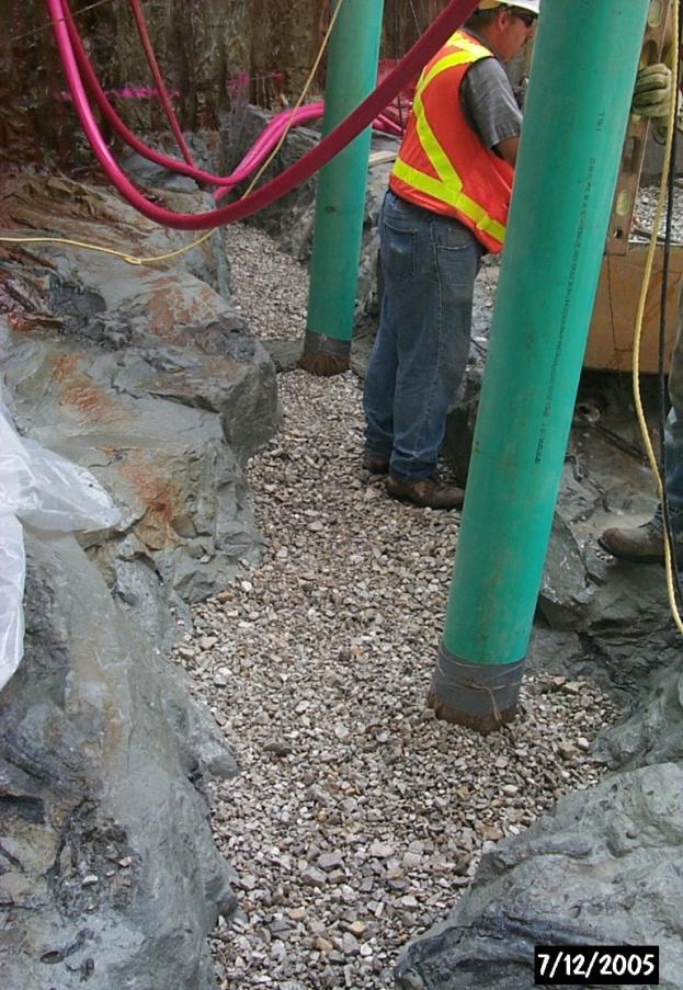
30 Dewater and Control Groundwater Seepage Primary Discharge Pump Sand Bags & Sump Pump Control of Seepage - Sidewalls


31 Provisions in Specifications Concerning Artesian Pressure Control Artesian Pressures: Grouting for Foundation Anchor Installation Foundation Drilling and Grouting


32 Foundation Drilling and Grouting Grout Curtain Inhibits Groundwater Flow Into Lock Chamber Grout Curtain Extends to Elevation Spacing Between Primary and Secondary Holes Optional Tertiary and Higher Order Holes

33 Top of Rock Surface Gravel Filter at Base of Retaining Wall Know Location of Top of Rock Surface: Sheet Pile Driven to Rock Cofferdam & Retaining Wall Seepage Cutoff Wall Through Soil Key into Rock
 - Project Description - Site Geology - Permeability and Groundwater Inflow - Dewatering Provisions 2.")
34 BEDROCK DEWATERING FOR CONSTRUCTION OUTLINE 1. Marmet Lock Replacement Project (construction) - Project Description - Site Geology - Permeability and Groundwater Inflow - Dewatering Provisions 2. Soo Lock Replacement Project (design) - Project Description - Site Geology - Permeability and Predicted Groundwater Inflow - Impact to Design
35 SOO LOCKS PROJECT DESCRIPTION SOO LOCKS OHIIO RIVER GREAT LAKES DIVISION Located in Michigan s Upper Peninsula at Sault Ste. Marie and near Canadian boarder. All shipping in/out of Lake Superior travels through Soo Locks New lock is in plans and specifications phase. Partial cofferdam has been constructed and approach channel deepened.

36 ONTARIO ST. MARYS RIVER FALLS OF THE ST. MARYS HYDROPOWER UNITS LOCKS MICHIGAN COMPENSATING WORKS Aerial View of Project - Taken From Upstream
37 N Aerial View of Locks

38 N Aerial View of Locks Proposed New Lock


39 SOO LOCKS SITE GEOLOGY - 76 Borings - 6,036 Total Feet of Exploratory Drilling - 4,139 Feet of Coring - 24 Piezometers Subsurface Exploration Boring Location Plan


40 Subsurface Exploration Down Hole Testing 496 Pressure Tests 21 Borehole Jack Tests 1,000 of Down-the-Hole Camera Images

41 General Geology Soil and rock fill 0 to 35 feet thick Natural top of rock dips downstream (1%) altered by past excavations Jacobsville Sandstone Formation (Cambrian Age) - interbedded sandstones Hard Sandstone Member Moderately Hard Sandstone Member Shaly & Weathered Sandstone Members Thin, continuous seams of clay, claystone and shale within sandstone. Bedding plane dip in a westerly direction at a 3 percent slope.


42 Bedrock Units Hard Sandstone HARD SANDSTONE MEMBER is typically light gray, light red or light purple with few light gray reduction spots, hard to very hard, fine to medium grained, occasionally cross bedded and medium to thick bedded. 12,400 psi Average Unconfined Compressive Strength Increased number of high-angled joints

43 Bedrock Units Moderately Hard Sandstone MODERATELY HARD SANDSTONE MEMBER is typically red with few to numerous light gray reduction spots, moderately hard, fine to medium grained and thin to medium bedded. 9,900 psi Average Unconfined Compressive Strength The predominant member sampled.


44 Bedrock Units Weathered and Shaly Sandstone WEATHERED SANDSTONE MEMBER is typically red with numerous light gray reduction spots, moderately hard, fine to medium grained, moderately weathered and thin bedded. SHALY SANDSTONE MEMBER is typically red to dark red with light gray reduction spots, soft to moderately hard, fine grained and thin bedded Increased number of weak / clay seams within these two members.

, laterally continuous and have")
.")

45 Bedrock Units Weak Seams WEAK / CLAY SEAMS are typically thin (ranging from 0.4-foot to 0.02-foot thick), laterally continuous and have a scattered vertical distribution (1-foot to 7-foot vertical spacing). These weak seams consist of: - Clay Seams - Clay Coated Bedding Planes - Zones of Severely Broken Rock - Claystone or claystone interlaminated with clay seams


46 Bedrock Fractures The predominant joint set orientation has been measured to have a dominant direction of N 70 o E, and a secondary direction of N 30 o E. Joints are typically high-angled (70 o to vertical) with a smooth and planar surface, occasionally displaying some discoloration of the bedrock, and aperture ranging from tight to open with occasional clay coating or filling. Few faults were noted during construction of Poe Lock. These were high angled with limited vertical extent.
47 Geologic Cross Section Existing Lock Chambers 600 EXISTING SABIN LOCK TOP OF GROUND TOP OF ROCK EXISTING DAVIS LOCK Soil and Rock Fill Moderately Hard Sandstone Member Hard Sandstone Member Weathered and Shaly Sandstone Members Continuous Weak/Clay Seams
48 Geologic Cross Section New Lock Chamber 600 NEW LOCK NEW CONCRETE ROCK ANCHORS Soil and Rock Fill Moderately Hard Sandstone Member Hard Sandstone Member Weathered and Shaly Sandstone Members Continuous Weak/Clay Seams

49 SOO LOCKS PERMEABILITY SABIN LOCK DAVIS LOCK PRESSURE TEST RESULTS Cross Section Pressure Testing Downstream Cofferdam

50 SABIN LOCK DAVIS LOCK PRESSURE TEST RESULTS Cross Section Pressure Testing Upstream Cofferdam
51 Hydraulic Conductivity Groundwater Inflow Hydraulic Conductivity or Permeability of the bedrock is determined from pressure test results. Average bedrock permeability at the Soo Lock Replacement Project located between top of rock surface and the excavated chamber elevation (533.6) is 5.4 x10⁻³ ft/min. Magnitude greater than Marmet L&D (3.3x10⁻⁴ ft/min) or Winfield L&D (6.9 x10⁻⁴ ft/min). Individual pressure tests resulted in localized permeability of 1.3x10⁻¹ ft/min (comparable to clean sand) and flow rates up to 9.3 cfm (70 gal/min) within a 5-foot increment. Estimated groundwater inflow through bedrock ranged from 1,480 to 2,625 gpm.


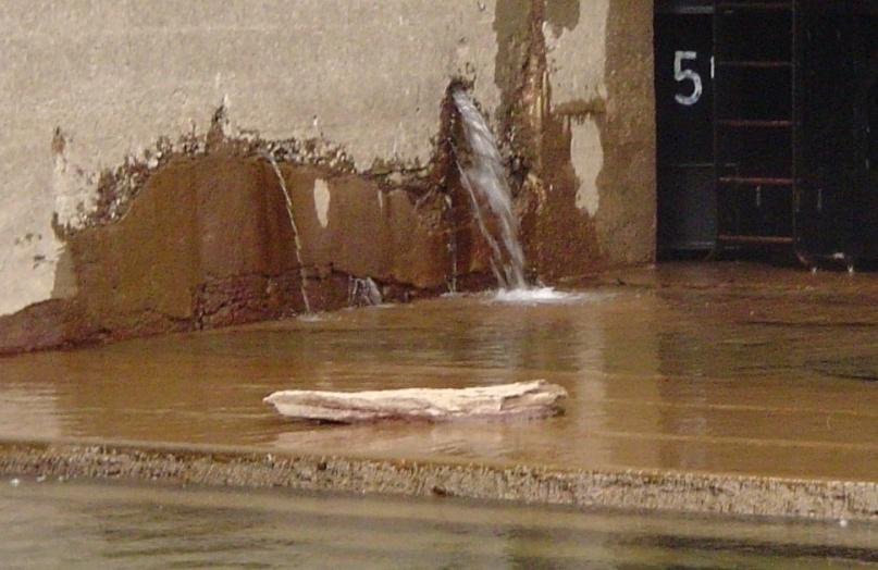
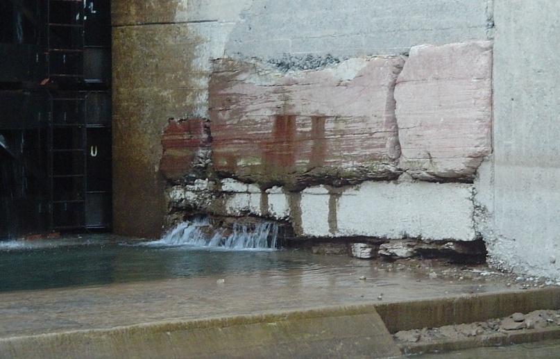
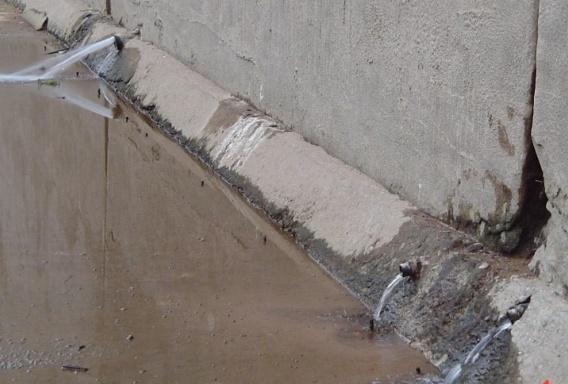
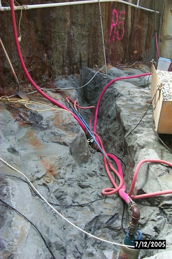
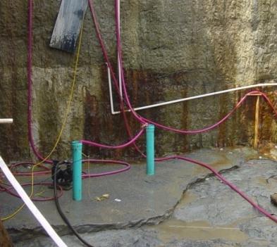
52 Seepage Through Bedrock During Dewatering
53 Groundwater Inflow During Construction Study performed in 2010 by Dr. Frank Schwartz, Ohio State University. Preliminary study with limited scope. Developed groundwater model using FTWORK, a finite-difference modeling package. Summary: Trial 1 dewater new lock excavation only, Trial 2 dewatered new lock and Davis Locks. Trial 3: same as 2 with conservative grout curtain, Trails 4&5: same as 3 with varying K values.


54 Groundwater Model Map of Model Grid in Relation to the Lock Structure


55 Groundwater Model Distribution of Hydraulic Head

56 SOO LOCKS IMPACTS TO DESIGN Grout Curtain for Dewatering Purposes - Upstream GROUT CURTAIN NEW LOCK Plan View Upstream Monoliths

57 Grout Curtain and Slurry Trench for Dewatering Purposes Downstream SLURRY TRENCH NEW LOCK GROUT CURTAIN Plan View Downstream Monoliths
58 Grout Curtain Details
59 Groundwater Flow Into Excavation Lock Chamber SOIL EXISTING NORTH DAVIS LOCKWALL NEW SOUTH WALL SKIRT WALL EXCAVATED LOCK CHAMBER NEW CULVERT BEDROCK HYDROSTATIC PRESSURE
60 Groundwater Flow Into Excavation Drainage Sheets SOIL EXISTING NORTH DAVIS LOCKWALL SKIRT WALL DRAINAGE SHEETS (Required to reduce hydrostatic pressure against Skirt Wall) BEDROCK HYDROSTATIC PRESSURE
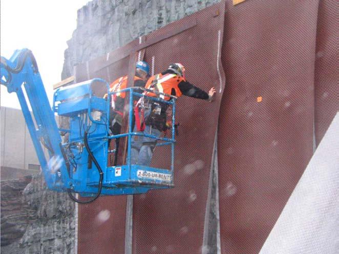


61 Groundwater Flow Into Excavation Drainage Sheet Details

62 BUILDING STRONG
10. GEOTECHNICAL EXPLORATION PROGRAM
 Geotechnical site investigations should be conducted in multiple phases to obtain data for use during the planning and design of the tunnel system. Geotechnical investigations typically are performed in
*** ***! " " ) * % )!( & ' % # $. 0 1 %./ +, - 7 : %8% 9 ) 7 / ( * 7 : %8% 9 < ;14. " > /' ;-,=. / ١
 * % )!( & ' % # $. 0 1 %./ +, - 7 : %8% 9 ) 7 / ( * 7 : %8% 9 < ;14. > /' ;-,=. / ١") ١ ******!" #$ % & '!( ) % * ") +,-./ % 01. 3 ( 4 56 7/4 ) 8%9 % : 7 ;14 < 8%9 % : *7./ = ;-, >/'." Soil Permeability & Seepage ٢ Soil Permeability- Definition ٣ What is Permeability? Permeability is the
١ ******!" #$ % & '!( ) % * ") +,-./ % 01. 3 ( 4 56 7/4 ) 8%9 % : 7 ;14 < 8%9 % : *7./ = ;-, >/'." Soil Permeability & Seepage ٢ Soil Permeability- Definition ٣ What is Permeability? Permeability is the
HOOVER DAM: Grout Curtain Failure and Lessons Learned in Site Characterization
 HOOVER DAM: Grout Curtain Failure and Lessons Learned in Site Characterization J. David Rogers Dams Symposium Association of Engineering Geologists Annual Meeting Las Vegas, Nevada September 22, 2005 The
ENCE 3610 Soil Mechanics. Site Exploration and Characterisation Field Exploration Methods
 ENCE 3610 Soil Mechanics Site Exploration and Characterisation Field Exploration Methods Geotechnical Involvement in Project Phases Planning Design Alternatives Preparation of Detailed Plans Final Design
Amistad Dam Investigation and Oversight: Karst- Founded Dam on the USA-Mexico Border
 Amistad Dam Investigation and Oversight: Karst- Founded Dam on the USA-Mexico Border Brook Brosi, CPG, PG USACE Lisa Nowicki Perks, PG USACE Kimberly Heenan, PE AECOM US Army Corps of Engineers BUILDING
b) EFFECTIVE STRESS (c) SEEPAGE
 EFFECTIVE STRESS (c) SEEPAGE") b) EFFECTIVE STRESS B1. A fine sand layer of 5 m thickness lies on a 5 m clay deposit. The water table is at the ground surface. Below the clay is a rock formation. Piezometers installed in the rock show
b) EFFECTIVE STRESS B1. A fine sand layer of 5 m thickness lies on a 5 m clay deposit. The water table is at the ground surface. Below the clay is a rock formation. Piezometers installed in the rock show
Chapter 7 Permeability and Seepage
 Permeability and Seepage - N. Sivakugan (2005) 1 7.1 INTRODUCTION Chapter 7 Permeability and Seepage Permeability, as the name implies (ability to permeate), is a measure of how easily a fluid can flow
BOLIVAR DAM GROUT CURTAIN CONSTRUCTION Muskingum River Basin, OH
 BOLIVAR DAM GROUT CURTAIN CONSTRUCTION Muskingum River Basin, OH AEG Annual Meeting September 2016 Mike Nield, Geologist U.S. Army Corps of Engineers, Huntington WV LRD Dam Safety Production Center Dam
Horizontal Directional Drilling: An Approach to Design and Construction. Presenter: John Briand, PE Co-Author: Danielle Neamtu, PE
 Horizontal Directional Drilling: An Approach to Design and Construction Presenter: John Briand, PE Co-Author: Danielle Neamtu, PE Presentation Outline General HDD overview Conceptual-level evaluation Detailed
ROCK EXCAVATION (GRADING) OPSS 206 INDEX
 OPSS 206 INDEX") 206-2 - OPSS 206 INDEX 206-2.1 GENERAL 206-2.1.1 Classification of Rock Materials 206-2.1.2 Tender Items 206-2.1.3 Other Excavation Tender Items 206-2.1.4 Specifications 206-2.1.5 Special Provisions 206-2.1.6
206-2 - OPSS 206 INDEX 206-2.1 GENERAL 206-2.1.1 Classification of Rock Materials 206-2.1.2 Tender Items 206-2.1.3 Other Excavation Tender Items 206-2.1.4 Specifications 206-2.1.5 Special Provisions 206-2.1.6
SITE INVESTIGATION 1
 SITE INVESTIGATION 1 Definition The process of determining the layers of natural soil deposits that will underlie a proposed structure and their physical properties is generally referred to as site investigation.
Seepage Analysis for Shurijeh Reservoir Dam Using Finite Element Method. S. Soleymani 1, A. Akhtarpur 2
 Seepage Analysis for Shurijeh Reservoir Dam Using Finite Element Method S. Soleymani 1, A. Akhtarpur 2 1 Group of Dam Construction, Toossab Company, P.O. Box 917751569, Mashhad City, Iran, PH (+98) 511-7684091;
Underground Drilling and Packer Test in Fault F16 of Wugou Coal Mine
 An Interdisciplinary Response to Mine Water Challenges - Sui, Sun & Wang (eds) 2014 China University of Mining and Technology Press, Xuzhou, ISBN 978-7-5645-0125-5 Underground Drilling and Packer Test
(Refer Slide Time: 02:10)
") Soil Mechanics Prof. B.V.S. Viswanathan Department of Civil Engineering Indian Institute of Technology, Bombay Lecture 24 Flow of water through soils-v Welcome to lecture five of flow of water through
Soil Mechanics Prof. B.V.S. Viswanathan Department of Civil Engineering Indian Institute of Technology, Bombay Lecture 24 Flow of water through soils-v Welcome to lecture five of flow of water through
11/22/2010. Groundwater in Unconsolidated Deposits. Alluvial (fluvial) deposits. - consist of gravel, sand, silt and clay
 deposits. - consist of gravel, sand, silt and clay") Groundwater in Unconsolidated Deposits Alluvial (fluvial) deposits - consist of gravel, sand, silt and clay - laid down by physical processes in rivers and flood plains - major sources for water supplies
Groundwater in Unconsolidated Deposits Alluvial (fluvial) deposits - consist of gravel, sand, silt and clay - laid down by physical processes in rivers and flood plains - major sources for water supplies
Slope Stability Evaluation Ground Anchor Construction Area White Point Landslide San Pedro District Los Angeles, California.
 Slope Stability Evaluation Ground Anchor Construction Area White Point Landslide San Pedro District Los Angeles, California Submitted To: Mr. Gene Edwards City of Los Angeles Department of Public Works
Boreholes. Implementation. Boring. Boreholes may be excavated by one of these methods: 1. Auger Boring 2. Wash Boring 3.
 Implementation Boreholes 1. Auger Boring 2. Wash Boring 3. Rotary Drilling Boring Boreholes may be excavated by one of these methods: 4. Percussion Drilling The right choice of method depends on: Ground
Materials. Use materials meeting the following.
 208.01 Section 208. SOIL EROSION AND SEDIMENTATION CONTROL 208.01 Description. Install and maintain erosion and sedimentation controls to minimize soil erosion and to control sedimentation from affecting
Geosynthetics Applications and Performance Reviews Select Case Histories
 Geosynthetics Applications and Performance Reviews Select Case Histories Debora J. Miller, Ph.D., P.E.; Dean B. Durkee,, Ph.D., P.E.; Michael A. Morrison, P.E., David B. Wilson, P.E., and Kevin Smith,
Converse Consultants Geotechnical Engineering, Environmental & Groundwater Science, Inspection & Testing Services
 Converse Consultants Geotechnical Engineering, Environmental & Groundwater Science, Inspection & Testing Services July 27, 2017 Ms. Rebecca Mitchell Mt. San Antonio College Facilities Planning & Management
Michigan s Geology and Groundwater
 Michigan s Geology and Groundwater Ralph J. Haefner Deputy Director U.S. Geological Survey Michigan-Ohio Water Science Center Lansing, Michigan Outline About the USGS Geology 101 Michigan s geology Bedrock
Engineering Geologic Conditions for Trenchless Application in the Denver Metro Area
 North American Society for Trenchless Technology (NASTT) NASTT s 2015 No-Dig Show Denver, Colorado March 15-19, 2015 Paper WM-T4-03 Engineering Geologic Conditions for Trenchless Application in the Denver
PROBLEMS AND SOLUTIONS THAT MAY EMERGE IN THE FOUNDATION AND BODY OF A HOMOGENEOUS FILL DAM ON A WEAK CLAYEY-SILTY-SANDY FORMATION ÇIKRIKÇI DAM
 PROBLEMS AND SOLUTIONS THAT MAY EMERGE IN THE FOUNDATION AND BODY OF A HOMOGENEOUS FILL DAM ON A WEAK CLAYEY-SILTY-SANDY FORMATION ÇIKRIKÇI DAM Esen Yalım KARADUMAN BAR-SU Eng. & Conc. Inc. Ankara Turkey
Gotechnical Investigations and Sampling
 Gotechnical Investigations and Sampling Amit Prashant Indian Institute of Technology Gandhinagar Short Course on Geotechnical Investigations for Structural Engineering 12 14 October, 2017 1 Purpose of
7. Foundation and Slope Stability
 The Asian Nuclear Safety Network 7. Foundation and Slope Stability (SER 2.5.4 & 2.5.5) Taek-Mo SHIM k147stm@kins.re.kr Korea Institute of Nuclear Safety Structural Systems and Site Evaluation Department
Prof. B V S Viswanadham, Department of Civil Engineering, IIT Bombay
 13 Permeability and Seepage -2 Conditions favourable for the formation quick sand Quick sand is not a type of sand but a flow condition occurring within a cohesion-less soil when its effective stress is
IAEA SAFETY STANDARDS Geotechnical Aspects of Site Evaluation and Foundations in NPPs, NS-G-3.6
 IAEA SAFETY STANDARDS Geotechnical Aspects of Site Evaluation and Foundations in NPPs, NS-G-3.6 Regional Workshop on Volcanic, Seismic, and Tsunami Hazard Assessment Related to NPP Siting Activities and
Geologging Imagery, Applications and Geological Interpretation. Shea Altadonna 1, Jim Fulton 2, E.I.T.
 Geologging Imagery, Applications and Geological Interpretation Shea Altadonna 1, Jim Fulton 2, E.I.T. 1 Geologist, Advanced Construction Techniques Inc. 1000 N. West St. Ste 1200, Wilmington, DE 19801;
Underground Excavation Design Classification
 Underground Excavation Design Underground Excavation Design Classification Alfred H. Zettler alfred.zettler@gmx.at Rock Quality Designation Measurement and calculation of RQD Rock Quality Designation index
Geotechnical Aspects of the Ohio River Bridges Project
 Geotechnical Aspects of the Ohio River Bridges Project Mark A. Litkenhus, PE Sr. Geotechnical Engineer Stephen H. Bickel, PE Sr. Geotechnical Engineer STGEC Ohio River Bridges at Louisville Geotechnical
 SOIL CLASSIFICATION CHART COARSE-GRAINED SOILS MORE THAN 50% RETAINED ON NO.200 SIEVE FINE-GRAINED SOILS 50% OR MORE PASSES THE NO.200 SIEVE PRIMARY DIVISIONS GRAVELS MORE THAN 50% OF COARSE FRACTION RETAINED
Data Report for White Point Landslide Boring B-12 W.O. E Task Order Solicitation San Pedro District Los Angeles, California
 Data Report for White Point Landslide Boring B-12 W.O. E1907483 Task Order Solicitation 11-087 San Pedro District Los Angeles, California Submitted To: Mr. Christopher F. Johnson, P.E., G.E. City of Los
 TP-1 N61E 0 DARK BROWN SANDY SILT (ML) stiff, wet with roots (Disturbed Surficial Soil) DEPTH (FEET) 5 REDDISH BROWN SANDSTONE intensely fractured, weak to friable, deeply weathered, tight (Franciscan
Geotechnical Engineering Report
 Geotechnical Engineering Report Turner Turnpike Widening Bridge D Bridge Crossing: South 209 th West Avenue Creek County, Oklahoma June 1, 2016 Terracon Project No. 04155197 Prepared for: Garver, LLC Tulsa,
Chapter 12 Subsurface Exploration
 Page 12 1 Chapter 12 Subsurface Exploration 1. The process of identifying the layers of deposits that underlie a proposed structure and their physical characteristics is generally referred to as (a) subsurface
Quantitative Classification of Rock Mass
 Quantitative Classification of Rock Mass Description of Joints: Orientation, Persistence, Roughness, Wall Strength, Aperture, Filling, Seepage, Number of sets, Block size, spacing. ISRM commission s i
IMWA Proceedings 1987 International Mine Water Association
 COAL MINE DEWATERING AS A KEY ASPECT IN PRE-MINE FEASIBILITY PLANNING IN THE SEMI-ARID WESTERN UNITED STATES Phillip E. Brown Consultant in Geohydrology 1401 Monaco Parkway Denver, Colorado 87220 USA Marcie
Subsurface Geology of the Kennebec River
 Maine Geologic Facts and Localities July, 1998 Subsurface Geology of the Kennebec River 43 54 40.75 N, 69 48 29.01 W Text by Daniel B. Locke, Department of Agriculture, Conservation & Forestry 1 Map by
SLOPE STABILITY EVALUATION AND ACCEPTANCE STANDARDS
 INFORMATION BULLETIN / PUBLIC - BUILDING CODE REFERENCE NO.: LABC 7006.3, 7014.1 Effective: 01-01-2017 DOCUMENT NO.: P/BC 2017-049 Revised: 12-21-2016 Previously Issued As: P/BC 2014-049 SLOPE STABILITY
A test boring program was utilized in this study in order to verify. existing information, and to obtain otherwise unavailable data that was
 TEST BORING RESULTS A test boring program was utilized in this study in order to verify existing information, and to obtain otherwise unavailable data that was considered vital for the formulation of an
USE OF GEOPHYSICAL SURVEYS FOR FILL CHARACTERIZATION AND QUANTITY ESTIMATION AT BROWNFIELD SITES A CASE HISTORY. Abstract
 USE OF GEOPHYSICAL SURVEYS FOR FILL CHARACTERIZATION AND QUANTITY ESTIMATION AT BROWNFIELD SITES A CASE HISTORY John A. Mundell, Mundell & Associates, Inc., Indianapolis, IN Gregory B. Byer, Mundell &
THE MINISTRY OF ENERGY AND ENERGY INDUSTRIES MINERALS DIVISION MINE DESIGN TEMPLATE OPERATOR NAME: OPERATOR ADDRESS: PHONE NUMBER: FACSIMILE:
 THE MINISTRY OF ENERGY AND ENERGY INDUSTRIES MINERALS DIVISION MINE DESIGN TEMPLATE 1.0 GENERAL INFORMATION OPERATOR NAME: OPERATOR ADDRESS: PHONE NUMBER: FACSIMILE: NAME OF CONTACT: CELLULAR PHONE: EMAIL
AVON DAM MONITORING BOREHOLES REPORT
 AVON DAM MONITORING BOREHOLES REPORT September 2015 Melinda Smart Supervisor Brownfields Exploration Energy and Engineering S2313 AND S2314 MONITORING BOREHOLES Avon Dam Hole 1 (S2313) and Avon Dam Hole
HOW. HOW vehicle mounted units portable units also available. HOW, WHEN & WHY to Geophysically Log in S.I.?
 HOW, WHEN & WHY to Geophysically Log in S.I.? by Kim Beesley HOW HOW vehicle mounted units portable units also available Access to borehole Depth of borehole sump / rat -hole? 1 HOW? - subject to borehole
MONITORING SEEPAGE FLOW THROUGH CARUACHI LEFT EMBANKMENT DAM DURING INITIAL RESERVOIR FILLING
 MONITORING SEEPAGE FLOW THROUGH CARUACHI LEFT EMBANKMENT DAM DURING INITIAL RESERVOIR FILLING EMILIO MARTINEZ Senior Hydraulic Engineer, Department of Hydraulic, CVG EDELCA Hid. Macagua I, Apartado 28
Finding Large Capacity Groundwater Supplies for Irrigation
 Finding Large Capacity Groundwater Supplies for Irrigation December 14, 2012 Presented by: Michael L. Chapman, Jr., PG Irrigation Well Site Evaluation Background Investigation Identify Hydrogeologic Conditions
Appendix J. Geological Investigation
 Appendix J Geological Investigation Appendix J Geological Environment Table of Contents Page 1 INTRODUCTION...J-1 1.1 Purpose of the Investigation...J-1 1.2 Scope of the Investigation...J-1 2 METHODO OF
HISTORY OF CONSTRUCTION FOR EXISTING CCR SURFACE IMPOUNDMENT PLANT GASTON ASH POND 40 CFR (c)(1)(i) (xii)
(1)(i) (xii)") HISTORY OF CONSTRUCTION FOR EXISTING CCR SURFACE IMPOUNDMENT PLANT GASTON ASH POND 40 CFR 257.73(c)(1)(i) (xii) (i) Site Name and Ownership Information: Site Name: E.C. Gaston Steam Plant Site Location:
HISTORY OF CONSTRUCTION FOR EXISTING CCR SURFACE IMPOUNDMENT PLANT GASTON ASH POND 40 CFR 257.73(c)(1)(i) (xii) (i) Site Name and Ownership Information: Site Name: E.C. Gaston Steam Plant Site Location:
A. Baiocchi 1, W. Dragoni 2, F. Lotti 1, S.M. Piacentini 2, V. Piscopo 1
 A. Baiocchi 1, W. Dragoni 2, F. Lotti 1, S.M. Piacentini 2, V. Piscopo 1 (1) Department of Ecological and Biological Sciences, University of Tuscia, Viterbo, Italy (2) Department of Physics and Geology,
Geology 229 Engineering Geology. Lecture 7. Rocks and Concrete as Engineering Material (West, Ch. 6)
") Geology 229 Engineering Geology Lecture 7 Rocks and Concrete as Engineering Material (West, Ch. 6) Outline of this Lecture 1. Rock mass properties Weakness planes control rock mass strength; Rock textures;
Geology 229 Engineering Geology Lecture 7 Rocks and Concrete as Engineering Material (West, Ch. 6) Outline of this Lecture 1. Rock mass properties Weakness planes control rock mass strength; Rock textures;
APPENDIX C. Borehole Data
 APPENDIX C Borehole Data MAJOR DIVISIONS SOIL CLASSIFICATION CHART SYMBOLS GRAPH LETTER TYPICAL DESCRIPTIONS ADDITIONAL MATERIAL
14 Geotechnical Hazards
 Volume 2: Assessment of Environmental Effects 296 14 Geotechnical Hazards Overview This Chapter provides an assessment of the underlying geotechnical conditions to identify: any potential liquefaction
KDOT Geotechnical Manual Edition. Table of Contents
 KDOT Geotechnical Manual 2007 Edition The KDOT Geotechnical Manual is available two volumes. Both volumes are very large electronic (pdf) files which may take several minutes to download. The table of
SLOPE STABILITY EVALUATION AND ACCEPTANCE STANDARDS
 INFORMATION BULLETIN / PUBLIC - BUILDING CODE REFERENCE NO.: LAMC 98.0508 Effective: 1-26-84 DOCUMENT NO. P/BC 2002-049 Revised: 11-1-02 Previously Issued As: RGA #1-84 SLOPE STABILITY EVALUATION AND ACCEPTANCE
Module 2 Lecture 9 Permeability and Seepage -5 Topics
 Module 2 Lecture 9 Permeability and Seepage -5 Topics 1.2.7 Numerical Analysis of Seepage 1.2.8 Seepage Force per Unit Volume of Soil Mass 1.2.9 Safety of Hydraulic Structures against Piping 1.2.10 Calculation
Pressure Grouting of Fractured Bedrock to Control Acid Mine Drainage
 WATER RESOURCES AT RISK May 14-18, 1995 Denver American Institute of Hydrology Pressure Grouting of Fractured Bedrock to Control Acid Mine Drainage S. A. Effner, G. D. Vandersluis, and V. Straskraba Hydro-Geo
Instructor : Dr. Jehad Hamad. Chapter (7)
") Instructor : Dr. Jehad Hamad Chapter (7) 2017-2016 Soil Properties Physical Properties Mechanical Properties Gradation and Structure Compressibility Soil-Water Relationships Shear Strength Bearing Capacity
Instructor : Dr. Jehad Hamad Chapter (7) 2017-2016 Soil Properties Physical Properties Mechanical Properties Gradation and Structure Compressibility Soil-Water Relationships Shear Strength Bearing Capacity
Coating Requirements for Pipelines Installed by Horizontal Directional Drilling John D. Hair, P.E.*
 Coating Requirements for Pipelines Installed by Horizontal Directional Drilling John D. Hair, P.E.* *President, J. D. Hair & Associates, Inc., 2121 South Columbia Avenue, Suite 101, Tulsa, OK 74114-3502;
Rock Foundation Course No. SE0104 PDH: 6
 Rock Foundation Course No. SE0104 PDH: 6 In order to obtain credit for this course, the following steps listed below should be followed: (1) Log into MyCE Account & purchase course. If you don t have an
STRUCTURAL STABILITY ASSESSMENT
 STRUCTURAL STABILITY ASSESSMENT CFR 257.73(d) Bottom Ash Pond Complex Cardinal Plant Brilliant, Ohio October, 2016 Prepared for: Cardinal Operating Company Cardinal Plant Brilliant, Ohio Prepared by: Geotechnical
PERENNIAL PROBLEM OF EARTHEN BUND OF WELLINGDON RESERVOIR. ANALYSIS OF CAUSES AND REMEDIAL MEASURES A CASE STUDY.
 PERENNIAL PROBLEM OF EARTHEN BUND OF WELLINGDON RESERVOIR. ANALYSIS OF CAUSES AND REMEDIAL MEASURES A CASE STUDY. By Er. S. Muthu Parvatha Vardhini, Asst. Executive Engineer, (Designs) Water Resources
Practical methodology for inclusion of uplift and pore pressures in analysis of concrete dams
 Practical methodology for inclusion of uplift and pore pressures in analysis of concrete dams Michael McKay 1 and Francisco Lopez 2 1 Dams Engineer, GHD Pty 2 Principal Dams/Structural Engineer, GHD Pty
Starting at Rock Bottom
 Starting at Rock Bottom At rock bottom of the Brushy Creek site s geological column lies the first clue to human habitation: A smelting and heattreating furnace, and mold, carved into Bed Ked: Figure 15
Appendix 6 Geotechnical report
 Page 56 Appendix 6 Geotechnical report 1. Introduction The following provides an initial and preliminary description/assessment of the overall geology, the likely ground conditions and preliminary geotechnical
Geotechnical Engineering Report
 Geotechnical Engineering Report Turner Turnpike Widening Bridge B Bridge Crossing: South 257 th West Avenue Creek County, Oklahoma June 1, 2016 Terracon Project No. 04155197 Prepared for: Garver, LLC Tulsa,
APPENDIX E SOILS TEST REPORTS
 Otsego County, NY Site Work Specifications APPENDIX E SOILS TEST REPORTS Blue Wing Services, Inc. July 1, 2010 Blue Wing Services May 20, 2010 Page 2 the site, was not made available to Empire at this
Hydrogeological Assessment for Part of Lots 2 and 3, Concession 5, Township of Thurlow, County of Hastings 1.0 INTRODUCTION. 1.
 February 10,2017 25506400 Ontario Ltd. Foxboro, ON Attention: Brad Newbatt Re: Hydrogeological Assessment for Part of Lots 2 and 3, Concession 5, Township of Thurlow, County of Hastings 1.0 INTRODUCTION
the Quarrying Industry Dewatering and the Quarrying Industry the Quarrying Industry
 Dewatering and the Quarrying Industry Dewatering and Dewatering and the Quarrying Industry the Quarrying Industry Les Brown Eugene P. Daly John Kelly Objectives 1) To present a summary of water management
Underground Risk Management Course Marina Del Rey, California November, Geotechnical Data Reports. Greg Raines, PE
 Underground Risk Management Course Marina Del Rey, California November, 2018 Geotechnical Data Reports Greg Raines, PE Gregory.Raines@Stantec.com Introduction What is a Geotechnical Data Report? The GDR
GEOPHYSICAL IMAGING TO ENHANCE ANALYSIS, DESIGN AND DRILLING OF LARGE-SCALE GEOTHERMAL SYSTEMS. Abstract
 GEOPHYSICAL IMAGING TO ENHANCE ANALYSIS, DESIGN AND DRILLING OF LARGE-SCALE GEOTHERMAL SYSTEMS John A. Mundell, Mundell & Associates, Inc., Indianapolis, Indiana Gabriel Hebert, Mundell & Associates, Inc.,
Early Exploration Permit Activity Information
 Early Exploration Permit Activity Information Activities That Require an Early Exploration Permit: Line cutting that is a width greater than 1.5 metres Mechanized stripping of a total surface area of greater
B805 TEMPORARY EROSION AND SEDIMENT CONTROL MEASURES - OPSS 805
 B805 MEASURES - OPSS 805 805.1 GENERAL Construction activities frequently remove protective cover and expose soil to accelerated rates of erosion. Sediments generated thereby can be conveyed via runoff
Soils, Hydrogeology, and Aquifer Properties. Philip B. Bedient 2006 Rice University
 Soils, Hydrogeology, and Aquifer Properties Philip B. Bedient 2006 Rice University Charbeneau, 2000. Basin Hydrologic Cycle Global Water Supply Distribution 3% of earth s water is fresh - 97% oceans 1%
Drilled Shaft Foundations in Limestone. Dan Brown, P.E., Ph.D. Dan Brown and Associates
 Drilled Shaft Foundations in Limestone Dan Brown, P.E., Ph.D. Dan Brown and Associates Foundation Engineering How we teach our students Fundamental understanding of soil and rock behavior (good!) Focus
PECivilExam.com. Copyright 2015 Pecivilexam.com all rights reserved- E-Book Geotechnical Depth Exam: 80 problems
 PECivilExam.com PE Civil Exam 80- Geotechnical Questions & Answers (pdf Format) For Depth Exam (Evening Session) PE Civil Depth Exam (Evening Session): This practice exam contains 80- Geotechnical questions,
CONSTRUCTION DEWATERING AT SALUDA DAM
 CONSTRUCTION DEWATERING AT SALUDA DAM Paul C. Rizzo, P.E., Ph.D., Jeffrey M. Bair. P.E., John P. Osterle, P.E., Howard W. Gault, P.G. Saluda Dam, owned and operated by South Carolina Electric & Gas Company
AWRA PMAS Engineers Club of Philadelphia. A Geologic Perspective on Stormwater
 AWRA PMAS Engineers Club of Philadelphia A Geologic Perspective on Stormwater Toby J. Kessler, P.G. Hydrogeologist Trevor G. Woodward, P.G. Engineering Geologist September 10, 2014 Gilmore & Associates,
3.12 Geology and Topography Affected Environment
 3 Affected Environment and Environmental Consequences 3.12 Geology and Topography 3.12.1 Affected Environment 3.12.1.1 Earthquakes Sterling Highway MP 45 60 Project Draft SEIS The Kenai Peninsula is predisposed
LEGEND ODOT CLASS. A-4b. A-6a. A-6b TOTAL VISUAL WEATHERED SANDSTONE VISUAL BORING LOCATION - PLAN VIEW
 PROJECT THE PROJECT CONSISTS IN PART OF ACING TWO STRUCTURES, EASTBOUND AND WESTBOUND STRUCTURES, RESPECTIVELY FOR THE PROPOSED SR OVER BLUE ROAD (CR 9). THE TWO STRUCTURES AS ANNED, ARE SINGLE-SPAN STRUCTURES
A BOOKLET ON. T Rangasamy, A R Leach and A P Cook. Facilitating safety and health research in the South African mining industry
 A BOOKLET ON THE HYDRAULIC DESIGN OF COAL BARRIER PILLARS T Rangasamy, A R Leach and A P Cook Facilitating safety and health research in the South African mining industry A BOOKLET ON THE HYDRAULIC DESIGN
Geotechnical Engineering Report
 Geotechnical Engineering Report Turner Turnpike Widening Polecat Creek Bridge (Bridge A) June 1, 2016 Terracon Project No. 04155197 Prepared for: Garver, LLC Prepared by: Terracon Consultants, Inc. TABLE
Notes Week 1 Engineering Geology Problems
 Notes Week 1 Engineering Geology Problems The Big Three of Engineering Geology 1. Will the ground bear the weight? (i.e. Subsurface materials? Rock or soft soil and sediment? Differential settlement?)
Geotechnical Data Report
 Geotechnical Data Report Downtown Greenville Future Conveyance Study December 1, 2015 Terracon Project No. 86155032 Prepared for: Prepared by: Terracon Consultants, Inc. December 1, 2015 561 Mauldin Road
Groundwater Hydrology
 EXERCISE 12 Groundwater Hydrology INTRODUCTION Groundwater is an important component of the hydrologic cycle. It feeds lakes, rivers, wetlands, and reservoirs; it supplies water for domestic, municipal,
Depth (ft) USCS Soil Description TOPSOIL & FOREST DUFF
 USCS Soil Description TOPSOIL & FOREST DUFF") Test Pit No. TP-6 Location: Latitude 47.543003, Longitude -121.980441 Approximate Ground Surface Elevation: 1,132 feet Depth (ft) USCS Soil Description 0 1.5 1.5 5.0 SM 5.0 8.0 SM Loose to medium dense,
Test Pit No. TP-6 Location: Latitude 47.543003, Longitude -121.980441 Approximate Ground Surface Elevation: 1,132 feet Depth (ft) USCS Soil Description 0 1.5 1.5 5.0 SM 5.0 8.0 SM Loose to medium dense,
A. V T = 1 B. Ms = 1 C. Vs = 1 D. Vv = 1
 Geology and Soil Mechanics 55401 /1A (2002-2003) Mark the best answer on the multiple choice answer sheet. 1. Soil mechanics is the application of hydraulics, geology and mechanics to problems relating
APPALACHIAN COLLUVIAL
 LANDSLIDE PROBLEMS ON APPALACHIAN COLLUVIAL SLOPES Geohazards in Transportation in the Appalachian Region Charleston, WV August 5 7, 2008 RICHARD E. GRAY DIGIOIA, GRAY & ASSOCIATES, LLC. 570 BEATTY ROAD
Geology and Soil Mechanics /1A ( ) Mark the best answer on the multiple choice answer sheet.
 Mark the best answer on the multiple choice answer sheet.") Geology and Soil Mechanics 55401 /1A (2003-2004) Mark the best answer on the multiple choice answer sheet. 1. Soil mechanics is the application of hydraulics, geology and mechanics to problems relating
Geology and Soil Mechanics 55401 /1A (2003-2004) Mark the best answer on the multiple choice answer sheet. 1. Soil mechanics is the application of hydraulics, geology and mechanics to problems relating
The process of determining the layers of natural soil deposits that will underlie a proposed structure and their physical properties is generally
 The process of determining the layers of natural soil deposits that will underlie a proposed structure and their physical properties is generally referred to as sub surface investigation 2 1 For proper
Engineer. Engineering. Engineering. (in-ja-neer ) A person trained and skilled in any of the various branches of engineering: a civil engineer
 A person trained and skilled in any of the various branches of engineering: a civil engineer") Engineer (in-ja-neer ) A person trained and skilled in any of the various branches of engineering: a civil engineer (Random House Webster s College Dictionary, 1991) CE100 Introduction to Civil Geotechnical
Engineer (in-ja-neer ) A person trained and skilled in any of the various branches of engineering: a civil engineer (Random House Webster s College Dictionary, 1991) CE100 Introduction to Civil Geotechnical
Measurement of effective stress shear strength of rock
 Measurement of effective stress shear strength of rock R. A. Failmezger, P.E., F. ASCE In-Situ Soil Testing, L.C., Lancaster, Virginia USA D. J. White, Ph. D., P.E. Iowa State University, Ames, Iowa USA
IN SITU SPECIFIC GRAVITY VS GRAIN SIZE: A BETTER METHOD TO ESTIMATE NEW WORK DREDGING PRODUCTION
 IN SITU SPECIFIC GRAVITY VS GRAIN SIZE: A BETTER METHOD TO ESTIMATE NEW WORK DREDGING PRODUCTION Nancy Case O Bourke, PE 1, Gregory L. Hartman, PE 2 and Paul Fuglevand, PE 3 ABSTRACT In-situ specific gravity
Instructional Objectives
 GE 6477 DISCONTINUOUS ROCK 8. Fracture Detection Dr. Norbert H. Maerz Missouri University of Science and Technology (573) 341-6714 norbert@mst.edu Instructional Objectives 1. List the advantages and disadvantages
Ohio Department of Transportation Division of Production Management Office of Geotechnical Engineering. Geotechnical Bulletin
 Ohio Department of Transportation Division of Production Management Office of Geotechnical Engineering Geotechnical Bulletin GB 3 ROCK CUT SLOPE & CATCHMENT DESIGN Geotechnical Bulletin GB3 was developed
Assistant Chief-Bureau of Structures and Geotechnical Services
 MEMO DATE: 2/10//2016 Bureau of Structures and Geotechnical Services TO: John Jones, P.E. Assistant Chief-Bureau of Structures and Geotechnical Services ATTENTION: Mark Hurt, P.E. Senior Bridge Squad Leader
Converse Consultants Geotechnical Engineering, Environmental & Groundwater Science, Inspection & Testing Services
 Converse Consultants Geotechnical Engineering, Environmental & Groundwater Science, Inspection & Testing Services Ms. Rebecca Mitchell Mt. San Antonio College Facilities Planning & Management 1100 North
ADVANCED SOIL MECHANICS
 BERNOULLI S EQUATION h Where: u w g Z h = Total Head u = Pressure = Velocity g = Acceleration due to Graity w = Unit Weight of Water h 14.531 ADVANCED SOIL MECHANICS BERNOULLI S EQUATION IN SOIL u w g
 Project: ITHACA-TOMPKINS REGIONAL AIRPORT EXPANSION Project Location: ITHACA, NY Project Number: 218-34 Key to Soil Symbols and Terms TERMS DESCRIBING CONSISTENCY OR CONDITION COARSE-GRAINED SOILS (major
Water in Soil Sections in Craig
 Water in Soil Sections 2.1-2.6 in Craig Outlines Introduction Darcy s Law Volume of water flowing per unit time Measuring K in laboratory Seepage Theory Flow Net Introduction All soils are permeable materials,
KRIS wsbssm. IBHiiilll
 KRIS wsbssm IBHiiilll Digitized by the Internet Archive in 2012 with funding from University of Illinois Urbana-Champaign http://archive.org/details/engineeringaspec34ekbl STATE OF ILLINOIS HENRY HORNER,