*** ***! " " ) * % )!( & ' % # $. 0 1 %./ +, - 7 : %8% 9 ) 7 / ( * 7 : %8% 9 < ;14. " > /' ;-,=. / ١
|
|
|
- James Harper
- 6 years ago
- Views:
Transcription
1 ١ ******!" #$ % & '!( ) % * ") +,-./ % ( /4 ) 8%9 % : 7 ;14 < 8%9 % : *7./ = ;-, >/'."
2 Soil Permeability & Seepage ٢
3 Soil Permeability- Definition ٣

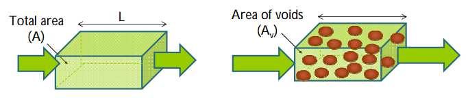
4 What is Permeability? Permeability is the measure of the soil s ability to permit water to flow through its pores or voids water Loose soil - easy to flow - high permeability Dense soil - difficult to flow - low permeability
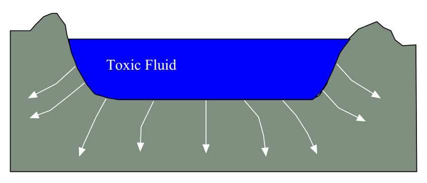
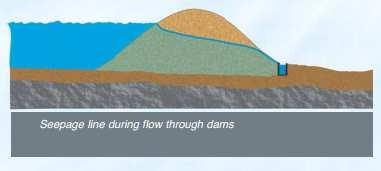
5 Importance of Permeability The following applications illustrate the importance of permeability in geotechnical design: The design of earth dams is very much based upon the permeability of the soils used. The stability of slopes and retaining structures can be greatly affected by the permeability of the soils involved. Filters made of soils are designed based upon their permeability. ٥

6 Importance of Permeability ٦
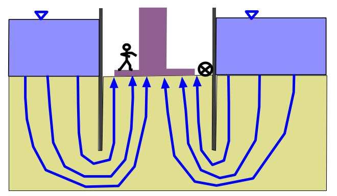
 Solving problems involving pumping seepage water from construction excavation")
7 Importance of Permeability Estimating the quantity of underground seepage (Ch. 8) Solving problems involving pumping seepage water from construction excavation ٧
8 Flow rate through soil What is the flow rate through a soil? Concrete dam SOIL Flow rate = Q [m 3 /sec]
9 ٩
10 ١٠
11 tank of water A B
12 Why does water flow? If flow is from A to B, the energy is higher at A than at B. Energy is dissipated in overcoming the soil resistance and hence is the head loss. water A B ١٢

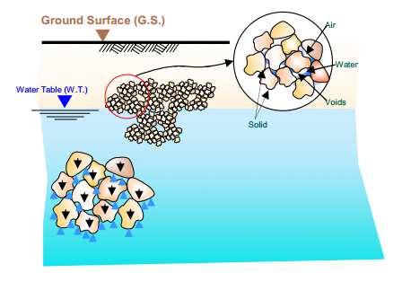
13 Soil Permeability -Definition Soils consists of solid particles with interconnected voids where water can flow from a point of high energy to a point of low energy water ١٣
14 Bernoulli s Equation The energy of fluid comprise of: 1. Potential energy - due to elevation (z) with respect to a datum fluid particle z - due to pressure 2. Kinetic energy - due to velocity datum ١٤
15 ١٥
16 ١٦
17 Soil piezometer h p A u = γ w h p Pressure head at A. The pore water pressure at A is
18 Hydrostatic pore water pressure u h = γ w h p z w1 u h = γ w z w1 z w z w2 u h = γ w z w 2 Depth, z
19 Bernoulli s Equation Then at any point in the fluid, the total energy is equal to Total Energy = Potential energy + Pressure energy + Kinetic energy = mgh + P + ½mv 2 Expressing the total energy as head (units of length) Total Head = Elevation Head + Pressure Head + Velocity Head h = Z + u γ + w 2 2 v g 0 For flow through soils, velocity (and thus velocity head) is very small. Therefore, v 2 /2g = zero.
20 ٢٠
21 ٢١

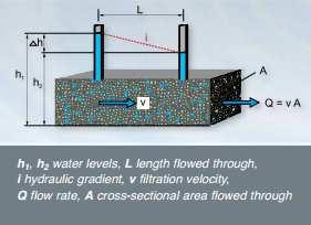
22 Bernoulli s Equation At any point w u Z h γ + = The head loss between A and B + + = = w B B w A A B A u Z u Z h h h γ γ Head loss in non-dimensional form L h i = Hydraulic gradient Distance between points A and B Difference in total head
 Water out h B Z A Z B")
23 W.T. Impervious Soil )h = h A - h B Water In h A Impervious Soil W.T. Datum h B Head Loss or Head Difference or Energy Loss i = Hydraulic Gradient h A (q) Water out h B Z A Z B Datum
24 Seepage Through Porous Media Water In L = Drainage Path i = Hydraulic Gradient Head Loss or Head Difference or Energy Loss h A Water out h B A Soil B Datum Porous Stone L Porous Stone
25 Seepage Through Porous Media Water In L = Drainage Path i = Hydraulic Gradient Head Loss or Head Difference or Energy Loss )h =h A - h B h A Water out h B A Soil B Z A Porous Stone L Porous Stone Z B Datum
26 Tricky case!! Remember always to look at total head P B /γ w P A /γ w
27 Hydraulic Gradient In the field, the gradient of the head is the head difference over the distance separating the 2 wells. i H H X 1 2 = ٢٧
28 Also..
29 WaterMovement in Soil Two Principles to Remember: 1. Darcy s Law 2. Continuity Equation: mass in = mass out + change in storage

30 Darcy s Law Assumptions: flow is laminar soil properties do not with time
31 Darcy s Law Since velocity in soil is small, flow can be considered laminar v i v = discharge velocity = i = hydraulic gradient v = k i k = coefficient of permeability Q = kia Cross-sectional area to flow Hydraulic conductivity permeability [cm/s] Hydraulic gradient
32 k Units are in cm/sec but k = velocity
33 Flow in Soil W.T. A Impervious Soil h = h A - h B L W.T. h A = total head B Datum Impervious Soil h B = total head i = ( h A L h B ) = h L Q = k i A = k h L A
34 Solution Q = kia k = 4x10⁻² cm/sec i = h/l = (167.3m 165m) / 256m = A = (3.2 m) (1000 m) = 3200 m 2 Q = kia = m 3 /sec = 41.5 m 3 /hr
35
36 ٣٦
37 Hydraulic Conductivity The hydraulic conductivity k is a measure of how easy the water can flow through the soil. The hydraulic conductivity is expressed in the units of velocity (such as cm/sec and m/sec). ٣٧
38 k Measure of a soil-fluid system s resistance to flow depends on soil Void size Fabric (structure) Void continuity Specific surface (drag) fluid Viscosity Mass density
39 Hydraulic Conductivity Hydraulic conductivity of soils depends on several factors: Fluid viscosity (η): as the viscosity increases, the hydraulic conductivity decreases Pore size distribution Temperature Grain size distribution Degree of soil saturation It is conventional to express the value of k at a temperature of 20 o C. ٣٩
40 ٤٠
41 To determine the quantity of flow, two parameters are needed * k = hydraulic conductivity * i = hydraulic gradient k can be determined using 1- Laboratory Testing [constant head test & falling head test] 2- Field Testing [pumping from wells] 3- Empirical Equations i can be determined 1- from the head loss and geometry 2- flow net (chapter 8)
42 Laboratory Testing of Hydraulic Conductivity Two standard laboratory tests are used to determine the hydraulic conductivity of soil The constant-head test The falling-head test. ٤٢

43 Constant Head Test ٤٣
44 Constant Head Test From Darcy s Law Then compute: ٤٤

45 Constant Head Test ٤٥
46

47 Falling Head Test The falling head test is mainly for fine-grained soils. Simplified Procedure: Record initial head difference, h 1 at t 1 = 0 Allow water to flow through the soil specimen Record the final head difference, h 2 at time t = t 2 Then compute: ٤٧
48 Falling Head Test ٤٨
49 Limitations of Laboratory tests for Hydraulic Conductivity i. It is generally hard to duplicate in-situ soil conditions (such as stratification). ii. The structure of in-situ soils may be disturbed because of sampling and test preparation. iii. Small size of laboratory samples lead to effects of boundary conditions.
50 ٥٠
51 ٥١
52 ٥٢
53 ٥٣
54 ٥٤


55 Equivalent Hydraulic Conductivity on Stratified Soils Horizontal flow Constant hydraulic gradient conditions Analogous to resistors in series
56 Equivalent Coefficient of Vertical Permeability (kv ) q = A* v = H * kh'* i average H. kh'. i = k. H. i + k. H. i k. H. i n n kh k. H + k. H ' = 2 H k n. H n


57 Equivalent Hydraulic Conductivity on Stratified Soils Vertical flow Constant velocity Analogous to resistors in parallel
58 Equivalent Coefficient of Vertical Permeability (kv ) Equivalent Coefficient of Vertical Permeability (kv ) Equivalent Coefficient of Vertical Permeability (kv ) Equivalent Coefficient of Vertical Permeability (kv ) Basic Concept q in = q out v constant n n n H h k H h k H h k i kv v ' = = = = = v h k H... v h k H ; v h k H ; v h k H n n n = = = = n n n k H... k H k H k H v h... v h v h v h = H H H H H n = n H n k k H k H k H H kv =... '
59
60 EXAMPLE 2 Questions : - determine h - determine q in cc/sec q Section 1 Section 2
61 EXAMPLE 2 Determination of h Section 1 Section 2 q = k 1 1.i1. A1 q 1 q 2 = k 2.i 2. A2 50 h h 5 = q2 = q = q (50 h) = ( h 5) Bina Nusantara h = cm
62 EXAMPLE 2 Determination of water flow rate q = k 1 1.i1. A1 or q = k 2 2.i 2. A2 q = q = 0.15 cc/s Bina Nusantara
63 Determination of Hydraulic conductivity in the Field 1. Pumping Wells with observation holes 2. Borehole test. 3. Packer Test.
 r r 2 1 k OR r2 q.")
64 Pumping Well with Observation holes Pumping Well in an Unconfined Aquifer q k = q π ( h 2 2.log h ) r r 2 1 k OR r2 q.ln r = π ( h h ) If q, h 1, h 2, r 1, r 2 are known, k can be calculated


65 Stress Concept
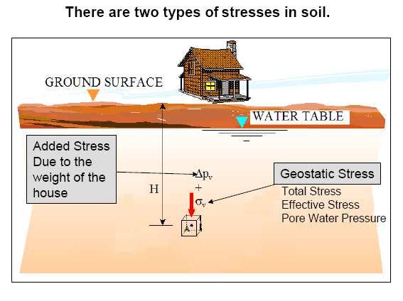
66 Stresses in Soils 1. Geostatic Stresses 2. Induced Stresses Due to soil s self weight Due to added loads (structures) 3. Dynamic Stresses e.g., earthquakes AS i g t i
67 ٦٧
68 ٦٨
69 ٦٩
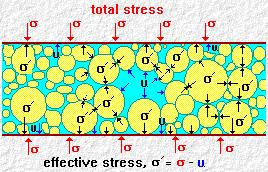
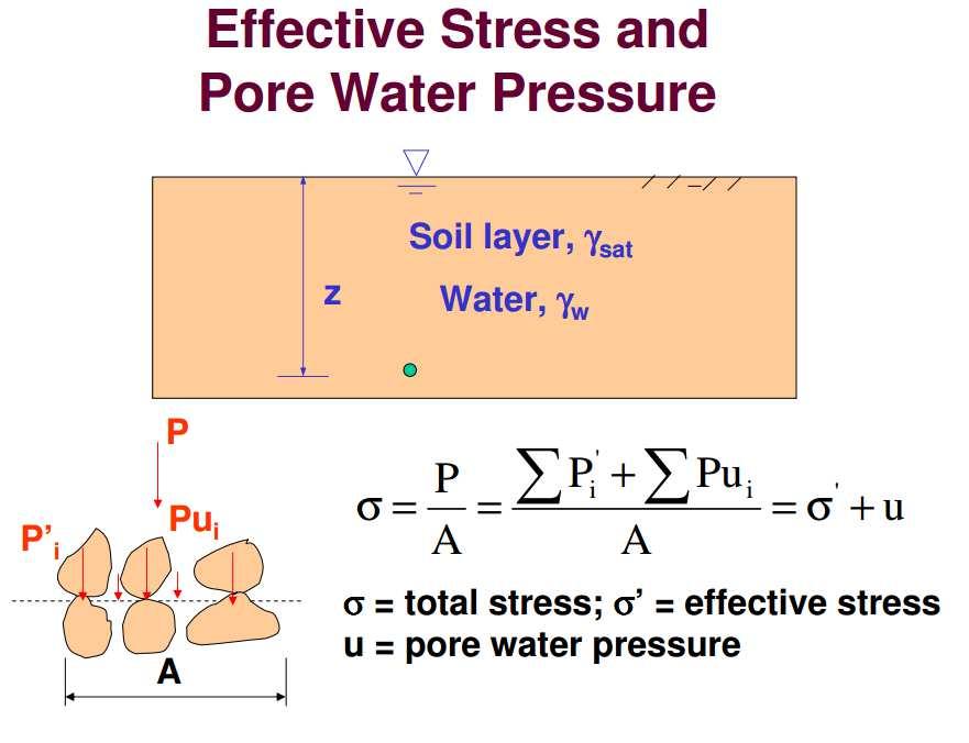
70 Effective Stress Spring Analogy σ = σ u P σ σ = effective stress σ= total stress * u = pore pressure X σ u
71 Geostatic Stresses SHEAR STRESSES If ground surface is flat, all geostatic shear stresses = zero
72 ٧٢
73 ٧٣
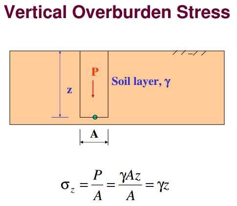
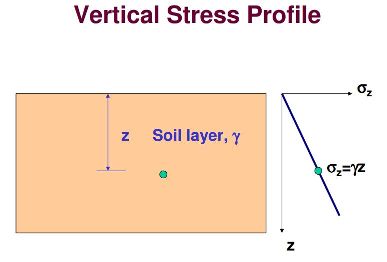
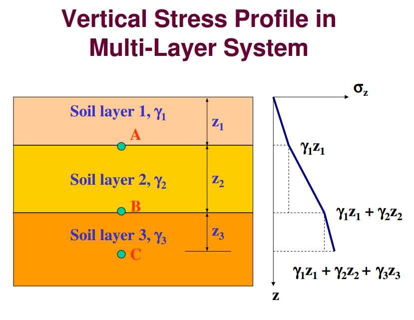
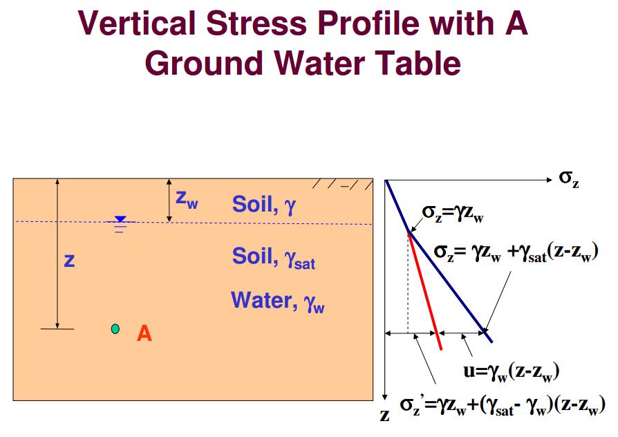
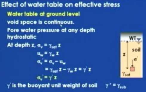
74 Geostatic Stresses TOTAL VERTICAL STRESS AT A POINT Ground surface z = depth = 5 m Soil, γ = 18 kn/m 3 A σ = γ z A A total vertical stress at A
75 ٧٥
76 ٧٦
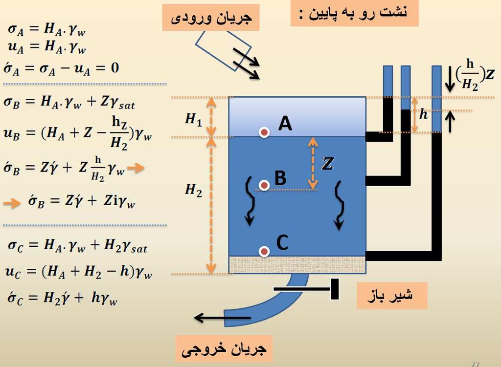
77 Pore water pressures u hydrostatic = u h = due to hydrostatic condition only u excess = u e = due to additional processes u = u + u e h
78 Geostatic Stresses PORE WATER PRESSURE AT A POINT Ground surface z = 5 m Soil, γ = 18 kn/m 3 h pa A u A = γ w h p A pore water pressure at A
79 ٧٩
80 ٨٠
81 ٨١
82 ٨٢
83 ٨٣
84 ٨٤

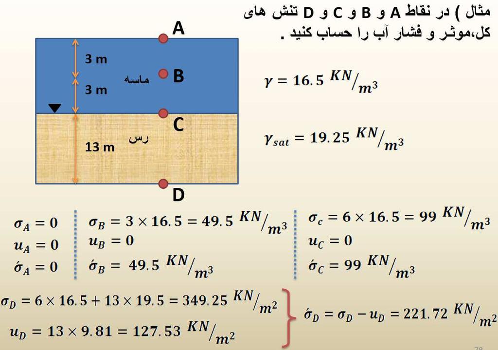
85 EXAMPLE Plot the variation of total and effective vertical stresses, and pore water pressure with depth for the soil profile shown below in Fig. ٨٥
86 Solution: Within a soil layer, the unit weight is constant, and therefore the stresses vary linearly. Therefore, it is adequate if we compute the values at the layer interfaces and water table location, and join them by straight lines. ٨٦

87 Pore Water Pressure ٨٧

88 Effective Stress General Expression ٨٨

89 Methods of Computations Effective Stress ٨٩
90 In Flow Piezometer 3 ft No Seepage D C Out Flow 2 ft 14 ft u = 14 x 62.4 u = 6 x 62.4 B 4 ft 12 ft W s 8 ft W s W s W s W s A Buoyancy 3 ft 3 ft Datum
91 W s W s W s W s W s Buoyancy ٩١
92 No Seepage 1 W.T. γ 1 =110 pcf 3 ft 4 ft 2 - = 6 ft 3 12 ft 4 Total Stress Pore Water Pressure Effective Stress W W s W s s W s W s Buoyancy
93 No Seepage 1 1 γ 1 =110 pcf 2 2 W.T. 3 ft 4 ft = 6 ft ft 5 5 Total Stress Pore Water Effective Stress Pressure Total Stress Pore Water Pressure Effective Stress σ1 = σ2 = σ3 = u1 = u2 = u3 = σ1 = σ2 = σ3 = σ4 = u4 = σ4 = σ5 = u5 = σ5 = W s W s W s W s Buoyancy W s
94 1 No Seepage W.T. γ 1 =110 pcf 2 3 ft 3 ft 4 ft 3 - = 6 ft 4 12 ft 5 Total Stress Pore Water Pressure Effective Stress W W s W s s W s W s Buoyancy
95 Downward Seepage Piezometer D In Flow 3 ft Out Flow u = 6 x u C 4 ft 2 ft 10 ft u = 17 x 62.4 B 12 ft Seepage Force 8 ft W s W s W s W s W s A Buoyancy - Seepage Force 3 ft 3 ft Datum
96 Seepage Force W s W s W s W s W s Buoyancy - Seepage Force ٩٦
97 Downward Seepage 1 γ 1 =110 pcf 1 W.T. 3 ft 3 ft 4 ft = 6 ft ft Total Stress 4 Pore Water Pressure 4 Effective Stress Seepage Force Total Stress Pore Water Pressure Effective Stress W s W s W s W s W s Buoyancy - Seepage Force
98 In Flow Piezometer Upward Seepage u D 3 ft u = 6 x u C Out Flow 4 ft 2 ft 17 ft u = 17 x 62.4 B 8 ft 12 ft W s W s W s W s W s A Buoyancy + Seepage Force 3 ft 3 ft Datum
99 W s W s W s W s W s Buoyancy + Seepage Force ٩٩
100 Upward Seepage 5 ft 2 1 γ 1 =110 pcf W.T. 3 ft 4 ft 3 - = 6 ft 4 12 ft Total Stress 54 Total Stress Pore Water Pressure Pore Water Pressure 4 Effective Stress Effective Stress W s W s W s W s W s Buoyancy + Seepage Force
101 γ 1 =110 pcf W.T. 3 ft W.T. 3 ft 4 ft 4 ft 6 ft 6 ft 12 ft 12 ft
102
103
104
105
106 SEEPAGE FORCE γ w. h 2. A H L Soil weight = γ t.l.a h 1 h 2 γ w. h 1. A L TOTAL FORCE F = γ. L. A γ.( h h A t w 1 2 ). BODY FORCE Body Force( F) = Total Force volume
107 SEEPAGE FORCE F F F γ L A h = L. A H + L = γ t γ w L = γ i. γ t.. γ w.( 1 2 bouyancy w h ). A = γ γ t w (1 + i) γ bouyancy = γ t - γ w SEEPAGE BODY FORCE (j)= CRITICAL CONDITION i. γ γ i w c bouyant = γ i. γ bouyant γ w w = = G 0 s 1+ 1 e
108 EXAMPLE : k = 1x10⁻³ cm/s n = 0.67 Questions : 1. Water Flow Rate 2. Flow Velocity 3. Seepage Velocity 4. Seepage Force at point A
109 Water Flow Rate H 4 q = k.i.a i = = = 1 L 4 Flow Velocity v = k.i v = 1x10.1 = 1x m / s q = 1x10.1.A = 1x A Seepage Velocity k.i v ' = = n v n 1*10 5 v ' = = 1.5x10 5 m / s 0.67 Seepage Force F s = i. γ w F = 1*1000 = 1000 kg / m s 2

110 Laplace equation of Continuity In reality, the flow of water through soil is not in one direction only, nor is it uniform over the entire area perpendicular to the flow. The flow of water in two dimensional is described using Laplace equation. Laplace equation is the combination of the equation of continuity and Darcy s law. ١١٠
111 Laplace equation of Continuity Flow in: v x dydz v z dxdy Flow out: v x vx + dx dydz x v Flow in = Flow out (Continuity equation) z + v z z dz dxdy By simplification, we get v v + x dx dydz + v v + z dz dxdy v dydz x z x z = x + v z dxdy v x x dxdydz + v z z dxdydz = 0 v x x + v z z = 0 ١١١
112 Laplace equation of Continuity From Darcy s Law: dh vx = kx vz = dx k z dh dz Replace in the continuity equation k x 2 h + k 2 x 2 h = 0 2 z If soil is isotropic (i.e. k x = k z = k) z 2 h 2 x + 2 h 2 z = 0 Laplace equation This equation governs the steady flow condition for a given point in the soil mass ١١٢

113 q = A k i = A k h L Equipotential Lines Flow Lines
114 Principles of the Flow Net Equipotential Lines Flow Element
115 Principles of the Flow Net )h = head loss = one drop Piezometer Flow Element Datum Equipotential Lines Total heads along this line are the same

116 Flow nets Flow nets are a graphical solution method of Laplace equation for 2D flow in a homogeneous, isotropic aquifer. In an isotropic medium, the continuity equation represents two orthogonal families of curves: 1. Flow lines: the line along which a water particle will travel from upstream to the downstream side in the permeable soil medium 2. Equipotential lines: the line along which the potential (pressure) head at all points is equal. Datum ١١٦


117 Flow nets Flow nets are the combination of flow lines and equipotential lines. To complete the graphic construction of a flow net, one must draw the flow and equipotential lines in such away that: 1. The equipotential lines intersect the flow lines at right angles. 2. The flow elements formed are approximate squares. Equipotential line Flow channel Flow line ١١٧

118 Boundary Conditions ١١٨
119 H 0 H ١١٩ H-3 h
120 ١٢٠

121 Seepage Calculation from Flow Net In a flow net, the strip between any two adjacent flow lines is called a flow channel. The drop in the total head between any two adjacent equipotential lines is called the potential drop. Flow element If the ratio of the sides of the flow element are the same along the flow channel, then: 1. Rate of flow through the flow channel per unit width perpendicular to the flow direction is the same. q 1 = q 2 = q 3 = q 2. The potential drop is the same and equal to: h h = h h = h h = Where H: head difference between the upstream and downstream sides. N ١٢١ d : number of potential drops H N d
122 Seepage Calculation from Flow Net ١٢٢ From Darcy s Equation, the rate of flow is equal to: If the number of flow channels in a flow net is equal to N f, the total rate of flow through all the channels per unit length can be given by: f = N d N H k q = = = = = N d H k q l l h h k l l h h k l l h h k q
123 Example on estimating the total flow under dam Example:if k = 10-7 m/sec, what would be the flow per day over a 100 m length of wall? 50 m of water Dam cutoff 5 m of water Low permeability rock ١٢٣
124 Calculations N f = 5 N d = 14 h= 45 m k= 10-7 m/sec Answer: = 10-7 (5/14) 45 x 100 m length = m 3 /sec = 13.9 m 3 /day ١٢٤
125 Pressure head at any point Total head = h L - # of drops from upstream x h Elevation head = -z Pressure head = Total head Elevation head = +ve h N L d datum H T = h L concrete dam H T = 0 h L z -ve h X impervious strata
126 In Flow )h )h )h )h )h )h )h )h 3 in Out Flow 2 in 8 14 in F eff = *( soil + * ( water - ( - )h) * ( water u = [14 - (3. )h)].( water 4 W s 3 W s W s 2 W s W s 1 2 Buoyancy + Seepage Force
 - (-2) = 7 kn/m 2 At point f: u a /γ w = (7-6x1) - (-2) = 3 kn/m 2 h = h L /N d =")
127 Uplift Pressure under Hydraulic structures At point a: u a /γ w = (7-1x1) - (-2) = 8 kn/m 2 At point b: Datum u a /γ w = (7-2x1) - (-2) = 7 kn/m 2 At point f: u a /γ w = (7-6x1) - (-2) = 3 kn/m 2 h = h L /N d = 7/7=1

128 Example of Dam Failure Around 7:00 am on June 5, 1976 a leak about 30 m from the top of Teton dam was observed. ١٢٨

129 Example of Dam Failure The Dam Broke at 11:59 AM ١٢٩
130 ١٣٠
131 ١٣١
132 ١٣٢
133 ١٣٣
134 Flow Nets: an example Posit ion: A B C D E F G H I J Dist ance f rom f ront t oe (ft) n The flow net is drawn with: m = 5 n =
135 Flow Nets: the solution Solve for the flow per unit width: q = (m/n) K h = (5/17)(150)(35) = 1544 ft 3 /day per ft 135
136 Flow Nets: An Example There is an earthen dam 13 meters across and 7.5 meters high.the Impounded water is 6.2 meters deep, while the tail water is 2.2 meters deep. The dam is 72 meters long. If the hydraulic conductivity is 6.1 x 10⁻⁴ centimeter per second, what is the seepage through the dam if n = 21 K = 6.1 x 10 4 cm/sec = m/day 136
137 Flow Nets: the solution From the flow net, the total head loss, H, is = 4.0 meters. There are 6 flow channels (m) and 21 head drops along each flow path (n): Q = (KmH/n) x dam length = (0.527 m/day x 6 x 4m / 21) x (dam length) = 0.60 m 3 /day per m of dam = 43.4 m 3 /day for the entire 72-meter length of the dam 137

138 Example of Dam Failure Post Failure Investigation Seepage piping and internal erosion Seepage through rock openings Hydraulic fracture Differential settlement and cracking Settlement in bedrock ١٣٨
139 Piping in Granular Soils At the downstream, near the dam, the exit hydraulic gradient i exit = h l H concrete dam l h = total head drop impervious strata
140 Piping in Granular Soils If i exit exceeds the critical hydraulic gradient (i c ), first the soil grains at exit get washed away. This phenomenon progresses towards the upstream, forming a free passage of water ( pipe ). concrete dam H no soil; all water impervious strata
141 Critical hydraulic gradient, i c The critical hydraulic gradient (i c ), γ = γ sat γ w Consequences: no stresses to hold granular soils together soil may flow boiling or piping = EROSION ١٤١
142 Piping in Granular Soils Piping is a very serious problem. It leads to downstream flooding which can result in loss of lives. Therefore, provide adequate safety factor against piping. F piping = i i c exit > 3 concrete dam impervious strata
143 Filters Used for: facilitating drainage preventing fines from being washed away Used in: earth dams retaining walls Filter Materials: granular soils geotextiless ١٤٣
144 Granular Filter Design The proper design of filters should satisfy two conditions: granular filter Condition 1: The size of the voids in the filter material should be small enough to hold the larger particles of the protected material in place Condition 2: The filter material should have a high hydraulic conductivity to prevent buildup of large seepage forces and hydrostatic pressures in the filters.
145 Granular Filter Design Condition 1: Condition 2: D D 15( filter) 85( soil ) 4 to 5 D D 15( filter) 15( soil ) 4 to 5 after Terzaghi & Peck (1967) D D 15( filter) 85( soil ) < 5 D D 15( filter ) 15( soil ) > 4 D D 50( filter) 50( soil ) < 25 after US Navy (1971) D15( filter) < 20 GSD D15( Curves soil ) for the soil and filter must be parallel
146 Granular Filter Design D D 15( filter) 85( soil ) 4 to 5 D D 15( filter) 15( soil ) 4 to 5 GSD of Soil GSD Curves for the soil and filter must be parallel
147 EXAMPLE A stiff clay layer underlies a 12 m thick silty sand deposit. A sheet pile is driven into the sand to a depth of 7 m, and the upstream and downstream water levels are as shown in the figure. Permeability of the silty sand is cm/s. The stiff clay can be assumed to be impervious. The void ratio of the silty sand is 0.72 and the specific gravity of the grains is (a) Estimate the seepage beneath the sheet pile in m 3 /day per meter. (b) What is the pore water pressure at the tip of the sheet pile? (c) Is the arrangement safe against piping? ١٤٧

148 EXAMPLE ١٤٨
149 Solution ١٤٩
Instructor : Dr. Jehad Hamad. Chapter (7)
") Instructor : Dr. Jehad Hamad Chapter (7) 2017-2016 Soil Properties Physical Properties Mechanical Properties Gradation and Structure Compressibility Soil-Water Relationships Shear Strength Bearing Capacity
Instructor : Dr. Jehad Hamad Chapter (7) 2017-2016 Soil Properties Physical Properties Mechanical Properties Gradation and Structure Compressibility Soil-Water Relationships Shear Strength Bearing Capacity
Chapter 7 Permeability and Seepage
 Permeability and Seepage - N. Sivakugan (2005) 1 7.1 INTRODUCTION Chapter 7 Permeability and Seepage Permeability, as the name implies (ability to permeate), is a measure of how easily a fluid can flow
(Refer Slide Time: 02:10)
") Soil Mechanics Prof. B.V.S. Viswanathan Department of Civil Engineering Indian Institute of Technology, Bombay Lecture 24 Flow of water through soils-v Welcome to lecture five of flow of water through
Soil Mechanics Prof. B.V.S. Viswanathan Department of Civil Engineering Indian Institute of Technology, Bombay Lecture 24 Flow of water through soils-v Welcome to lecture five of flow of water through
5. TWO-DIMENSIONAL FLOW OF WATER THROUGH SOILS 5.1 INTRODUCTION
 5. TWO-DIMENSIONAL FLOW OF WATER TROUG SOILS 5.1 INTRODUCTION In many instances the flo of ater through soils is neither one-dimensional nor uniform over the area perpendicular to flo. It is often necessary
Water in Soil Sections in Craig
 Water in Soil Sections 2.1-2.6 in Craig Outlines Introduction Darcy s Law Volume of water flowing per unit time Measuring K in laboratory Seepage Theory Flow Net Introduction All soils are permeable materials,
GEOTECHNICAL ENGINEERING II (Subject Code: 06CV64) UNIT 4: FLOW NETS 4.1 Introduction
 UNIT 4: FLOW NETS 4.1 Introduction") GEOTECHNICAL ENGINEERING II (Subject Code: 06CV64) UNIT 4: FLOW NETS 4.1 Introduction In this chapter the topics that are covered include principles of seepage analysis, graphical solutions for seepage
GEOTECHNICAL ENGINEERING II (Subject Code: 06CV64) UNIT 4: FLOW NETS 4.1 Introduction In this chapter the topics that are covered include principles of seepage analysis, graphical solutions for seepage
b) EFFECTIVE STRESS (c) SEEPAGE
 EFFECTIVE STRESS (c) SEEPAGE") b) EFFECTIVE STRESS B1. A fine sand layer of 5 m thickness lies on a 5 m clay deposit. The water table is at the ground surface. Below the clay is a rock formation. Piezometers installed in the rock show
b) EFFECTIVE STRESS B1. A fine sand layer of 5 m thickness lies on a 5 m clay deposit. The water table is at the ground surface. Below the clay is a rock formation. Piezometers installed in the rock show
Geo-E2010 Advanced Soil Mechanics L Wojciech Sołowski. 26 February 2017
 Geo-E2010 Advanced Soil Mechanics L Wojciech Sołowski 26 February 2017 Permeability, consolidation and seepage Department of Civil Engineering Advanced Soil Mechanics W. Sołowski 2 To learn 1. What is
Prof. B V S Viswanadham, Department of Civil Engineering, IIT Bombay
 13 Permeability and Seepage -2 Conditions favourable for the formation quick sand Quick sand is not a type of sand but a flow condition occurring within a cohesion-less soil when its effective stress is
Civil Engineering Department College of Engineering
 Civil Engineering Department College of Engineering Course: Soil Mechanics (CE 359) Lecturer: Dr. Frederick Owusu-Nimo FREQUENCY CE 260 Results (2013) 30 25 23 25 26 27 21 20 18 15 14 15 Civil Geological
ADVANCED SOIL MECHANICS
 BERNOULLI S EQUATION h Where: u w g Z h = Total Head u = Pressure = Velocity g = Acceleration due to Graity w = Unit Weight of Water h 14.531 ADVANCED SOIL MECHANICS BERNOULLI S EQUATION IN SOIL u w g
Module 2 Lecture 9 Permeability and Seepage -5 Topics
 Module 2 Lecture 9 Permeability and Seepage -5 Topics 1.2.7 Numerical Analysis of Seepage 1.2.8 Seepage Force per Unit Volume of Soil Mass 1.2.9 Safety of Hydraulic Structures against Piping 1.2.10 Calculation
All soils in natural are permeable materials, water being free to flow through the interconnected pores between the solid particles.
 8.1 Introduction Among construction materials, soil is very unique. Because of a relatively large space of void in its constituent, water can flow through soil. The water flow (seepage) characteristics
ADVANCED SOIL MECHANICS FINAL EXAM (TAKE HOME):DUE THURSDAY, DECEMBER 19, 6PM.
:DUE THURSDAY, DECEMBER 19, 6PM.") 14.531 ADVANCED SOIL MECHANICS FINAL EXAM (TAKE HOME):DUE THURSDAY, DECEMBER 19, 2013 @ 6PM. Problem #1. Field load tests on strip footings yielded the test data provided below in Figure 1 and Table 1
14.531 ADVANCED SOIL MECHANICS FINAL EXAM (TAKE HOME):DUE THURSDAY, DECEMBER 19, 2013 @ 6PM. Problem #1. Field load tests on strip footings yielded the test data provided below in Figure 1 and Table 1
YOUR HW MUST BE STAPLED YOU MUST USE A PENCIL (no pens)
") Spring 2008 CIVE 462 HOMEWORK #1 1. Print out the syllabus. Read it. Write the grade percentages in the first page of your notes. 2. Go back to your 301 notes, internet, etc. and find the engineering definition
Spring 2008 CIVE 462 HOMEWORK #1 1. Print out the syllabus. Read it. Write the grade percentages in the first page of your notes. 2. Go back to your 301 notes, internet, etc. and find the engineering definition
Permeability in Soils
 Permeability in Soils Contents: Darcy s law- assumption and validity, coefficient of permeability and its determination (laboratory and field), factors affecting permeability, permeability of stratified
 QUESTION BANK DEPARTMENT: CIVIL SUBJECT CODE / Name: CE 2251 / SOIL MECHANICS SEMESTER: IV UNIT 1- INTRODUCTION PART - A (2 marks) 1. Distinguish between Residual and Transported soil. (AUC May/June 2012)
VALLIAMMAI ENGINEERING COLLEGE
 VALLIAMMAI ENGINEERING COLLEGE DEPARTMENT OF CIVIL ENGINEERING SUBJECT CODE : CE6405 YEAR : II SUBJECT NAME : SOIL MECHANICS SEM : IV QUESTION BANK (As per Anna University 2013 regulation) UNIT 1- SOIL
Time Rate of Consolidation Settlement
 Time Rate of Consolidation Settlement We know how to evaluate total settlement of primary consolidation S c which will take place in a certain clay layer. However this settlement usually takes place over
PRINCIPLES OF GEOTECHNICAL ENGINEERING
 PRINCIPLES OF GEOTECHNICAL ENGINEERING Fourth Edition BRAJA M. DAS California State University, Sacramento I(T)P Boston Albany Bonn Cincinnati London Madrid Melbourne Mexico City New York Paris San Francisco
SOIL MECHANICS
 4.330 SOIL MECHANICS BERNOULLI S EQUATION Were: u w g Z = Total Head u = Pressure = Velocity g = Acceleration due to Graity w = Unit Weigt of Water Slide of 37 4.330 SOIL MECHANICS BERNOULLI S EQUATION
Distribution of pore water pressure in an earthen dam considering unsaturated-saturated seepage analysis
 E3S Web of Conferences 9, 194 (16) DOI: 1.11/ e3sconf/169194 E-UNSAT 16 Distribution of pore water in an earthen dam considering unsaturated-saturated seepage analysis 1a Kumar Venkatesh, Siva Ram Karumanchi
Tikrit University. College of Engineering Civil engineering Department CONSOILDATION. Soil Mechanics. 3 rd Class Lecture notes Up Copyrights 2016
 Tikrit University CONSOILDATION College of Engineering Civil engineering Department Soil Mechanics 3 rd Class Lecture notes Up Copyrights 2016 Stresses at a point in a soil mass are divided into two main
GEOTECHNICAL LABORATORY
 14.333 GEOTECHNICAL LABORATORY BERNOULLI S EQUATION h u w v 2 2g Z h = Total Head u = Pressure v = Velocity g = Acceleration due to Gravity w = Unit Weight of Water Slide 1 of 14 h 14.333 GEOTECHNICAL
Soil Mechanics Permeability of Soils and Seepage page 1 CHAPITRE 9. PERMEABILITY OF SOILS AND SEEPAGE...1
 Soil Mechanics Permeability of Soils and Seepage page 1 Contents of this chapter : CHAPITRE 9. PERMEABILITY OF SOILS AND SEEPAGE...1 9.1 INTRODUCTION...1 9.2 DARCY S LAW...1 9.2.1 DEFINITION OF HEAD...1
The Effects of Different Surcharge Pressures on 3-D Consolidation of Soil
 The Effects of Different Surcharge Pressures on 3-D Consolidation of Soil Arpan Laskar *1 and Sujit Kumar Pal 2 *1 Department of Civil Engineering, National Institute of Technology Agartala, Tripura, India.
Chapter 3 Permeability
 3.2 Darcy s Law In 1856, Darcy investigated the flow of water through sand filters for water purification. His experimental apparatus is shown in Figure 3.11. By empirical observation Figure 3.11 Schematic
International Journal of Scientific & Engineering Research, Volume 8, Issue 2, February ISSN
 P P International Journal of Scientific & Engineering Research, Volume 8, Issue 2, February-2017 1053 Effect of Impervious Core on Seepage through Zoned Earth Dam (Case Study: Khassa Chai Dam) Abstract
Geosynthetics Applications and Performance Reviews Select Case Histories
 Geosynthetics Applications and Performance Reviews Select Case Histories Debora J. Miller, Ph.D., P.E.; Dean B. Durkee,, Ph.D., P.E.; Michael A. Morrison, P.E., David B. Wilson, P.E., and Kevin Smith,
Table of Contents Chapter 1 Introduction to Geotechnical Engineering 1.1 Geotechnical Engineering 1.2 The Unique Nature of Soil and Rock Materials
 Table of Contents Chapter 1 Introduction to Geotechnical Engineering 1.1 Geotechnical Engineering 1.2 The Unique Nature of Soil and Rock Materials 1.3 Scope of This Book 1.4 Historical Development of Geotechnical
COMPARISION OF HYDRAULIC GRADIENT AND UPLIFT PRESSURE IN THREE TYPES OF DAMS: HOMOGENEOUS, HETEROGENEOUS EARTHFILL DAMS AND CONCRETE GRAVITY DAM
 SAJCCE 1:1 (2015) 91-103 October 2015 ISSN: 2394-2258 Available at http://scientificadvances.co.in DOI: http://dx.doi.org/10.18642/sajcce_7100121544 COMPARISION OF HYDRAULIC GRADIENT AND UPLIFT PRESSURE
The process of consolidation and settlement
 Consolidation Based on part of the GeotechniCAL reference package by Prof. John Atkinson, City University, London The process of consolidation and settlement One-dimensional consolidation theory The oedometer
Boreholes. Implementation. Boring. Boreholes may be excavated by one of these methods: 1. Auger Boring 2. Wash Boring 3.
 Implementation Boreholes 1. Auger Boring 2. Wash Boring 3. Rotary Drilling Boring Boreholes may be excavated by one of these methods: 4. Percussion Drilling The right choice of method depends on: Ground
Theory of Shear Strength
 MAJ 1013 ADVANCED SOIL MECHANICS Theory of Shear Strength Prepared by, Dr. Hetty 1 Strength of different materials Steel Concrete Soil Tensile strength Compressive strength Shear strength Complex behavior
CONSOLIDATION OF SOIL
 Lecture-6 Soil consolidation Dr. Attaullah Shah 1 CONSOLIDATION OF SOIL When a soil mass is subjected to a compressive force there is a decrease in volume of soil mass. The reduction in volume of a saturated
Introduction to Soil Mechanics
 Introduction to Soil Mechanics Sela Sode and Colin Jones WILEY Blackwell Contents Preface Dedication and Acknowledgments List of Symbols Soil Structure 1.1 Volume relationships 1.1.1 Voids ratio (e) 1.1.2
APPENDIX G APPENDIX G SEDIMENT CONTAINMENT SYSTEM DESIGN RATIONALE
 APPENDIX G SEDIMENT CONTAINMENT SYSTEM DESIGN RATIONALE March 18, 2003 This page left blank intentionally. March 18, 2003 G-2 FIGURES Page # Figure G.1 Estimated Runoff from Precipitation Over Different
Geotechnical Properties of Soil
 Geotechnical Properties of Soil 1 Soil Texture Particle size, shape and size distribution Coarse-textured (Gravel, Sand) Fine-textured (Silt, Clay) Visibility by the naked eye (0.05 mm is the approximate
A. V T = 1 B. Ms = 1 C. Vs = 1 D. Vv = 1
 Geology and Soil Mechanics 55401 /1A (2002-2003) Mark the best answer on the multiple choice answer sheet. 1. Soil mechanics is the application of hydraulics, geology and mechanics to problems relating
Geology and Soil Mechanics /1A ( ) Mark the best answer on the multiple choice answer sheet.
 Mark the best answer on the multiple choice answer sheet.") Geology and Soil Mechanics 55401 /1A (2003-2004) Mark the best answer on the multiple choice answer sheet. 1. Soil mechanics is the application of hydraulics, geology and mechanics to problems relating
Geology and Soil Mechanics 55401 /1A (2003-2004) Mark the best answer on the multiple choice answer sheet. 1. Soil mechanics is the application of hydraulics, geology and mechanics to problems relating
GEOSYNTHETICS ENGINEERING: IN THEORY AND PRACTICE
 GEOSYNTHETICS ENGINEERING: IN THEORY AND PRACTICE Prof. J. N. Mandal Department of civil engineering, IIT Bombay, Powai, Mumbai 400076, India. Tel.022-25767328 email: cejnm@civil.iitb.ac.in Module - 4
Laboratory Testing Total & Effective Stress Analysis
 SKAA 1713 SOIL MECHANICS Laboratory Testing Total & Effective Stress Analysis Prepared by: Dr. Hetty Mohr Coulomb failure criterion with Mohr circle of stress 2 ' 2 ' ' ' 3 ' 1 ' 3 ' 1 Cot Sin c ' ' 2
Effect of Location and Angle of Cutoff Wall on Uplift Pressure in Diversion Dam
 Geotech Geol Eng (2014) 32:1165 1173 DOI 10.1007/s10706-014-9774-3 ORIGINAL PAPER Effect of Location and Angle of Cutoff Wall on Uplift Pressure in Diversion Dam Behnam Mansuri Farzin Salmasi Behrooz Oghati
NUMERICAL AND EXPERIMENTAL ANALYSIS OF SEEPAGE BENEATH A MODEL OF A GRAVITY DAM
 Engineering Review Vol. 33, Issue 2, 75-84, 2013. 75 NUMERICAL AND EXPERIMENTAL ANALYSIS OF SEEPAGE BENEATH A MODEL OF A GRAVITY DAM T. Jelenkovi V. Travaš * Chair of Hydraulic Engineering, Faculty of
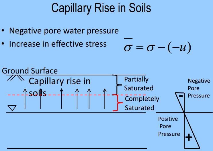
Soil Mechanics I 3 Water in Soils. 1. Capillarity, swelling 2. Seepage 3. Measurement of hydraulic conductivity 4. Effective stress in the ground
 Soil Mechanics I 3 Water in Soils 1. Capillarity, swelling 2. Seepage 3. Measurement of hydraulic conductivity 4. Effective stress in the ground 1 Influence of Water - Basics WATER IN SOIL - affects soil
Unsaturated Flow (brief lecture)
") Physical Hydrogeology Unsaturated Flow (brief lecture) Why study the unsaturated zone? Evapotranspiration Infiltration Toxic Waste Leak Irrigation UNSATURATAED ZONE Aquifer Important to: Agriculture (most
Physical Hydrogeology Unsaturated Flow (brief lecture) Why study the unsaturated zone? Evapotranspiration Infiltration Toxic Waste Leak Irrigation UNSATURATAED ZONE Aquifer Important to: Agriculture (most
Landslide FE Stability Analysis
 Landslide FE Stability Analysis L. Kellezi Dept. of Geotechnical Engineering, GEO-Danish Geotechnical Institute, Denmark S. Allkja Altea & Geostudio 2000, Albania P. B. Hansen Dept. of Geotechnical Engineering,
Class Principles of Foundation Engineering CEE430/530
 Class Principles of Foundation Engineering CEE430/530 1-1 General Information Lecturer: Scott A. Barnhill, P.E. Lecture Time: Thursday, 7:10 pm to 9:50 pm Classroom: Kaufmann, Room 224 Office Hour: I have
PERENNIAL PROBLEM OF EARTHEN BUND OF WELLINGDON RESERVOIR. ANALYSIS OF CAUSES AND REMEDIAL MEASURES A CASE STUDY.
 PERENNIAL PROBLEM OF EARTHEN BUND OF WELLINGDON RESERVOIR. ANALYSIS OF CAUSES AND REMEDIAL MEASURES A CASE STUDY. By Er. S. Muthu Parvatha Vardhini, Asst. Executive Engineer, (Designs) Water Resources
FUNDAMENTALS OF CONSOLIDATION
 FUNDAMENTALS OF CONSOLIDATION σ (Vertical Stress Increase) SAND CLAY CONSOLIDATION: Volume change in saturated soils caused by the expulsion of pore water from loading. Saturated Soils: σ causes u to increase
Theory of Shear Strength
 SKAA 1713 SOIL MECHANICS Theory of Shear Strength Prepared by, Dr. Hetty 1 SOIL STRENGTH DEFINITION Shear strength of a soil is the maximum internal resistance to applied shearing forces The maximum or
Course Scheme -UCE501: SOIL MECHANICS L T P Cr
 Course Scheme -UCE501: SOIL MECHANICS L T P Cr 3 1 2 4.5 Course Objective: To expose the students about the various index and engineering properties of soil. Introduction: Soil formation, various soil
Practical methodology for inclusion of uplift and pore pressures in analysis of concrete dams
 Practical methodology for inclusion of uplift and pore pressures in analysis of concrete dams Michael McKay 1 and Francisco Lopez 2 1 Dams Engineer, GHD Pty 2 Principal Dams/Structural Engineer, GHD Pty
We are IntechOpen, the world s leading publisher of Open Access books Built by scientists, for scientists. International authors and editors
 We are IntechOpen, the world s leading publisher of Open Access books Built by scientists, for scientists 3,500 108,000 1.7 M Open access books available International authors and editors Downloads Our
SHEAR STRENGTH OF SOIL
 Soil Failure Criteria SHEAR STRENGTH OF SOIL Knowledge about the shear strength of soil important for the analysis of: Bearing capacity of foundations, Slope stability, Lateral pressure on retaining structures,
Principles of Foundation Engineering 8th Edition Das SOLUTIONS MANUAL
 Principles of Foundation Engineering 8th Edition SOLUTIONS MANUAL Full clear download (no formatting errors) at: https://testbankreal.com/download/principles-foundation-engineering- 8th-edition-das-solutions-manual/
Darcy's Law. Laboratory 2 HWR 531/431
 Darcy's Law Laboratory HWR 531/431-1 Introduction In 1856, Henry Darcy, a French hydraulic engineer, published a report in which he described a series of experiments he had performed in an attempt to quantify
Chapter 12 Subsurface Exploration
 Page 12 1 Chapter 12 Subsurface Exploration 1. The process of identifying the layers of deposits that underlie a proposed structure and their physical characteristics is generally referred to as (a) subsurface
FLOW MEASUREMENT IN PIPES EXPERIMENT
 University of Leicester Engineering Department FLOW MEASUREMENT IN PIPES EXPERIMENT Page 1 FORMAL LABORATORY REPORT Name of the experiment: FLOW MEASUREMENT IN PIPES Author: Apollin nana chaazou Partner
Compressibility & Consolidation
 CHAPTER Compressibility & Consolidation Settlement If a structure is placed on soil surface, then the soil will undergo an elastic and plastic deformation. In engineering practice, the deformation or reduction
Seepage Analysis for Shurijeh Reservoir Dam Using Finite Element Method. S. Soleymani 1, A. Akhtarpur 2
 Seepage Analysis for Shurijeh Reservoir Dam Using Finite Element Method S. Soleymani 1, A. Akhtarpur 2 1 Group of Dam Construction, Toossab Company, P.O. Box 917751569, Mashhad City, Iran, PH (+98) 511-7684091;
CE 4780 Hurricane Engineering II. Section on Flooding Protection: Earth Retaining Structures and Slope Stability. Table of Content
 CE 4780 Hurricane Engineering II Section on Flooding Protection: Earth Retaining Structures and Slope Stability Dante Fratta Fall 00 Table of Content Introduction Shear Strength of Soils Seepage nalysis
Pit Slope Optimization Based on Hydrogeologic Inputs
 Pit Slope Optimization Based on Hydrogeologic Inputs G. Evin, F. Henriquez, V. Ugorets SRK Consulting (U.S.), Inc., Lakewood, Colorado, USA ABSTRACT With the variability of commodity prices and the constant
Chapter 2. 53% v. 2.2 a. From Eqs. (2.11) and (2.12), it can be seen that, 2.67
 and (2.12), it can be seen that, 2.67") Chapter 2 2.1 d. (87.5)(9.81) (1000)(0.05) 3 17.17 kn/m c. d 1 w 17.17 1 0.15 3 14.93 kn/m G a. Eq. (2.12): s w (2.68)(9.81). 14.93 ; e 0.76 1 e 1 e e 0.76 b. Eq. (2.6): n 0.43 1 e 1 0.76 Vw wgs (0.15)(2.68)
Chapter 2 2.1 d. (87.5)(9.81) (1000)(0.05) 3 17.17 kn/m c. d 1 w 17.17 1 0.15 3 14.93 kn/m G a. Eq. (2.12): s w (2.68)(9.81). 14.93 ; e 0.76 1 e 1 e e 0.76 b. Eq. (2.6): n 0.43 1 e 1 0.76 Vw wgs (0.15)(2.68)
Hydraulic conductivity of granular materials
 3 r d International Conference on New Developments in Soil Mechanics and Geotechnical Engineering, Hydraulic conductivity of granular materials Namir K.S.Al-Saoudi Building and construction Eng. Dept.
16 Rainfall on a Slope
 Rainfall on a Slope 16-1 16 Rainfall on a Slope 16.1 Problem Statement In this example, the stability of a generic slope is analyzed for two successive rainfall events of increasing intensity and decreasing
Table 17 1 Some general field equation terms. Heat Power. Current Source. 0 0 Boundary Current Porous Media Flow. Flow Source
 17 Related Analogies 17.1 Basic Concepts The differential equation used in a finite element study in one discipline often appears in a different discipline, but with a different physical meaning for the
SITE INVESTIGATION 1
 SITE INVESTIGATION 1 Definition The process of determining the layers of natural soil deposits that will underlie a proposed structure and their physical properties is generally referred to as site investigation.
SOIL SHEAR STRENGTH. Prepared by: Dr. Hetty Muhammad Azril Fauziah Kassim Norafida
 SOIL SHEAR STRENGTH Prepared by: Dr. Hetty Muhammad Azril Fauziah Kassim Norafida What is shear strength Shear strength of a soil is the maximum internal resistance to applied shearing forces Why it is
Seismic Stability of Tailings Dams, an Overview
 Seismic Stability of Tailings Dams, an Overview BY Gonzalo Castro, Ph.D., P.E. Principal International Workshop on Seismic Stability of Tailings Dams Case Western Reserve University, November 2003 Small
(Refer Slide Time: 01:15)
") Soil Mechanics Prof. B.V.S. Viswanathan Department of Civil Engineering Indian Institute of Technology, Bombay Lecture 56 Stability analysis of slopes II Welcome to lecture two on stability analysis of
Soil Mechanics Prof. B.V.S. Viswanathan Department of Civil Engineering Indian Institute of Technology, Bombay Lecture 56 Stability analysis of slopes II Welcome to lecture two on stability analysis of
Slope Stability. loader
 Slope Stability Slope Stability loader Lower San Fernando Dam Failure, 1971 Outlines Introduction Definition of key terms Some types of slope failure Some causes of slope failure Shear Strength of Soils
See discussions, stats, and author profiles for this publication at:
 See discussions, stats, and author profiles for this publication at: http://www.researchgate.net/publication/261179220 Analysis of Seepage Problem effects underneath Diyala Weir using 2-D model for the
EARTH PRESSURES ON RETAINING STRUCTURES
 12-1 12. EARTH PRESSURES ON RETAINING STRUCTURES 12.1 Active Pressure and Passive Pressure When a sudden change in level of the ground surface is to be provided for some purpose a retaining structure is
Prof. B V S Viswanadham, Department of Civil Engineering, IIT Bombay
 19 Module 5: Lecture -1 on Stability of Slopes Contents Stability analysis of a slope and finding critical slip surface; Sudden Draw down condition, effective stress and total stress analysis; Seismic
Interpretation of Flow Parameters from In-Situ Tests (P.W. Mayne, November 2001)
") Interpretation of Flow Parameters from In-Situ Tests (P.W. Mayne, November 2001) FLOW PROPERTIES Soils exhibit flow properties that control hydraulic conductivity (k), rates of consolidation, construction
Interpretation of Flow Parameters from In-Situ Tests (P.W. Mayne, November 2001) FLOW PROPERTIES Soils exhibit flow properties that control hydraulic conductivity (k), rates of consolidation, construction
LOADS ON EARTH-FILL AND ROCK-FILL DAMS ARISING FROM WATER AND WIND
 LOADS ON EARTH-FILL AND ROCK-FILL DAMS ARISING FROM WATER AND WIND B. Kjaernsli, T. Valstad, and K. Höeg Norwegian Geotechnical Institute, Oslo, Norway Keywords: Embankment dams, seepage and drainage,
Chapter (12) Instructor : Dr. Jehad Hamad
 Instructor : Dr. Jehad Hamad") Chapter (12) Instructor : Dr. Jehad Hamad 2017-2016 Chapter Outlines Shear strength in soils Direct shear test Unconfined Compression Test Tri-axial Test Shear Strength The strength of a material is the
Chapter (12) Instructor : Dr. Jehad Hamad 2017-2016 Chapter Outlines Shear strength in soils Direct shear test Unconfined Compression Test Tri-axial Test Shear Strength The strength of a material is the
Prof. B V S Viswanadham, Department of Civil Engineering, IIT Bombay
 31 Module 7: Lecture - 6 on Geotechnical Physical Modelling Scaling laws in centrifuge modelling Force, work, and energy Consider the definition of potential energy PE normally expressed as energy lost
FUNDAMENTALS SOIL MECHANICS. Isao Ishibashi Hemanta Hazarika. >C\ CRC Press J Taylor & Francis Group. Taylor & Francis Group, an Informa business
 SOIL MECHANICS FUNDAMENTALS Isao Ishibashi Hemanta Hazarika >C\ CRC Press J Taylor & Francis Group Boca Raton London New York CRC Press is an imprint of the Taylor & Francis Group, an Informa business
Erosion Rate is a Function of Erodibility and Excess Shear Stress = k ( o - c ) From Relation between Shear Stress and Erosion We Calculate c and
 From Relation between Shear Stress and Erosion We Calculate c and") Equilibrium, Shear Stress, Stream Power and Trends of Vertical Adjustment Andrew Simon USDA-ARS, Oxford, MS asimon@msa-oxford.ars.usda.gov Non-Cohesive versus Cohesive Materials Non-cohesive: sands and
Equilibrium, Shear Stress, Stream Power and Trends of Vertical Adjustment Andrew Simon USDA-ARS, Oxford, MS asimon@msa-oxford.ars.usda.gov Non-Cohesive versus Cohesive Materials Non-cohesive: sands and
Mechanical Energy. Kinetic Energy. Gravitational Potential Energy
 Mechanical Energy Kinetic Energy E k = 1 2 mv2 where E k is energy (kg-m 2 /s 2 ) v is velocity (m/s) Gravitational Potential Energy E g = W = mgz where w is work (kg-m 2 /s 2 ) m is mass (kg) z is elevation
1.91. kg m s. Solving for m s yields m s kg. Now we can use the fundamental definition of water content to get the mass of water. m w = 0.
 1 CE 46 - Homework #1 Solutions Problem #.1. Problem - A contractor will want to charge you more for coring through that "soft rock layer". However, your expertise tells you that that layer is not rock
Introduction to Geotechnical Engineering. ground
 Introduction to Geotechnical Engineering ground 1 Typical Geotechnical Project Geo-Laboratory ~ for testing soil properties Design Office ~ for design & analysis construction site 2 Shallow Foundations
THE EFFECT OF RESERVOIR WATER LEVEL FLUCTUATION TO THE SEEPAGE ON EARTH DAM
 Civil Engineering Forum Volume XXI/ - January THE EFFECT OF RESERVOIR WATER LEVEL FLUCTUATION TO THE SEEPAGE ON EARTH DAM H. Sudardja Civil Department, Politeknik Negeri Jakarta, Jakarta, INDONESIA Email:
APPENDIX F CORRELATION EQUATIONS. F 1 In-Situ Tests
 APPENDIX F 1 APPENDIX F CORRELATION EQUATIONS F 1 In-Situ Tests 1. SPT (1) Sand (Hatanaka and Uchida, 1996), = effective vertical stress = effective friction angle = atmosphere pressure (Shmertmann, 1975)
International Journal of Modern Trends in Engineering and Research
 Scientific Journal Impact Factor (SJIF): 1.711 e-issn: 2349-9745 p-issn: 2393-8161 International Journal of Modern Trends in Engineering and Research www.ijmter.com STABILITY ANALYSIS OF DOWNSTREAM SLOPE
D1. A normally consolidated clay has the following void ratio e versus effective stress σ relationship obtained in an oedometer test.
 (d) COMPRESSIBILITY AND CONSOLIDATION D1. A normally consolidated clay has the following void ratio e versus effective stress σ relationship obtained in an oedometer test. (a) Plot the e - σ curve. (b)
Calculation of 1-D Consolidation Settlement
 Calculation of 1-D Consolidation Settlement A general theory for consolidation, incorporating threedimensional flow is complicated and only applicable to a very limited range of problems in geotechnical
Ch 4a Stress, Strain and Shearing
 Ch. 4a - Stress, Strain, Shearing Page 1 Ch 4a Stress, Strain and Shearing Reading Assignment Ch. 4a Lecture Notes Sections 4.1-4.3 (Salgado) Other Materials Handout 4 Homework Assignment 3 Problems 4-13,
Chapter 1 - Soil Mechanics Review Part A
 Chapter 1 - Soil Mechanics Review Part A 1.1 Introduction Geotechnical Engineer is concerned with predicting / controlling Failure/Stability Deformations Influence of water (Seepage etc.) Soil behavour
J. Paul Guyer, P.E., R.A.
 J. Paul Guyer, P.E., R.A. Paul Guyer is a registered mechanical engineer, civil engineer, fire protection engineer and architect with over 35 years experience in the design of buildings and related infrastructure.
Seismic Design of a Hydraulic Fill Dam by Nonlinear Time History Method
 Seismic Design of a Hydraulic Fill Dam by Nonlinear Time History Method E. Yıldız & A.F. Gürdil Temelsu International Engineering Services Inc., Ankara, Turkey SUMMARY: Time history analyses conducted
STABILITY ANALYSIS OF EARTH DAM SLOPES SUBJECTED TO EARTHQUAKE USING ERT RESULTS INTERPRETATION
 STABILITY ANALYSIS OF EARTH DAM SLOPES SUBJECTED TO EARTHQUAKE USING ERT RESULTS INTERPRETATION Eko Andi Suryo Lecturer / Department of Civil Engineering, Faculty of Engineering / University of Brawijaya
Influence of Surrounding Soil Conditions and Joint Sealing on Seepage Resistance of a Sheet Pile Wall, Three Dimensional Numerical Analyses
 IOP Conference Series: Earth and Environmental Science PAPER OPEN ACCESS Influence of Surrounding Soil Conditions and Joint Sealing on Seepage Resistance of a Sheet Pile Wall, Three Dimensional Numerical
Permeability of Sandy Soil CIVE 2341 Section 2 Soil Mechanics Laboratory Experiment #5, Laboratory #6 SPRING 2015 Group #3
 Permeability of Sandy Soil CIVE 2341 Section 2 Soil Mechanics Laboratory Experiment #5, Laboratory #6 SPRING 2015 Group #3 Abstract: The purpose of this experiment was to determine the coefficient of permeability
SOIL MECHANICS: palgrave. Principles and Practice. Graham Barnes. macmiiian THIRD EDITION
 SOIL MECHANICS: Principles and Practice THIRD EDITION Graham Barnes palgrave macmiiian 'running Contents Preface xii Fine soil 19 List of symbols xiv Mass structure 21 Note on units xix Degree of weathering
Design of RC Retaining Walls
 Lecture - 09 Design of RC Retaining Walls By: Prof Dr. Qaisar Ali Civil Engineering Department UET Peshawar www.drqaisarali.com 1 Topics Retaining Walls Terms Related to Retaining Walls Types of Retaining
The Russian Practice of Assessment of Earth Dam Seepage Strength
 The Russian Practice of Assessment of Earth Dam Seepage Strength V. Radchenko I. Belkova O. Rumyantsev Vedeneev All-Russian Research Institute of Hydraulic Engineering Inc. (JSC «Vedeneev VNIIG») RusHydro
6.1 Water. The Water Cycle
 6.1 Water The Water Cycle Water constantly moves among the oceans, the atmosphere, the solid Earth, and the biosphere. This unending circulation of Earth s water supply is the water cycle. The Water Cycle