Instructor : Dr. Jehad Hamad. Chapter (7)
|
|
|
- Owen Sherman
- 6 years ago
- Views:
Transcription


1 Instructor : Dr. Jehad Hamad Chapter (7)


2 Soil Properties Physical Properties Mechanical Properties Gradation and Structure Compressibility Soil-Water Relationships Shear Strength Bearing Capacity Atterberg s Limits Soil Compaction Permeability

3 Permeability is the measure of the soil s ability to permit water to flow through its pores or voids

4 Applications Rate of settlement under load Dams Stability of slopes Filters
5 Permeability and seepage Soils are assemblages of solid particles with interconnected voids through which water can flow. The study of the flow of water through porous soil media is important in soil mechanics. 5 1/29/2017

6 Permeability and seepage For example: Pumping of water for underground constructions Stability analysis of earth dams Earth retaining structures subjected to 6 seepage forces. 1/29/2017
 can pass through")
7 What is permeability? A measure of how easily a fluid (e.g., water) can pass through a porous medium (e.g., soils) water Loose soil - easy to flow 7 - high permeability Dense soil - difficult to flow - low permeability
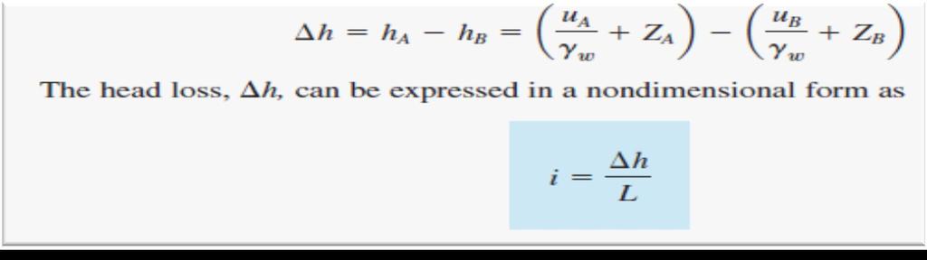
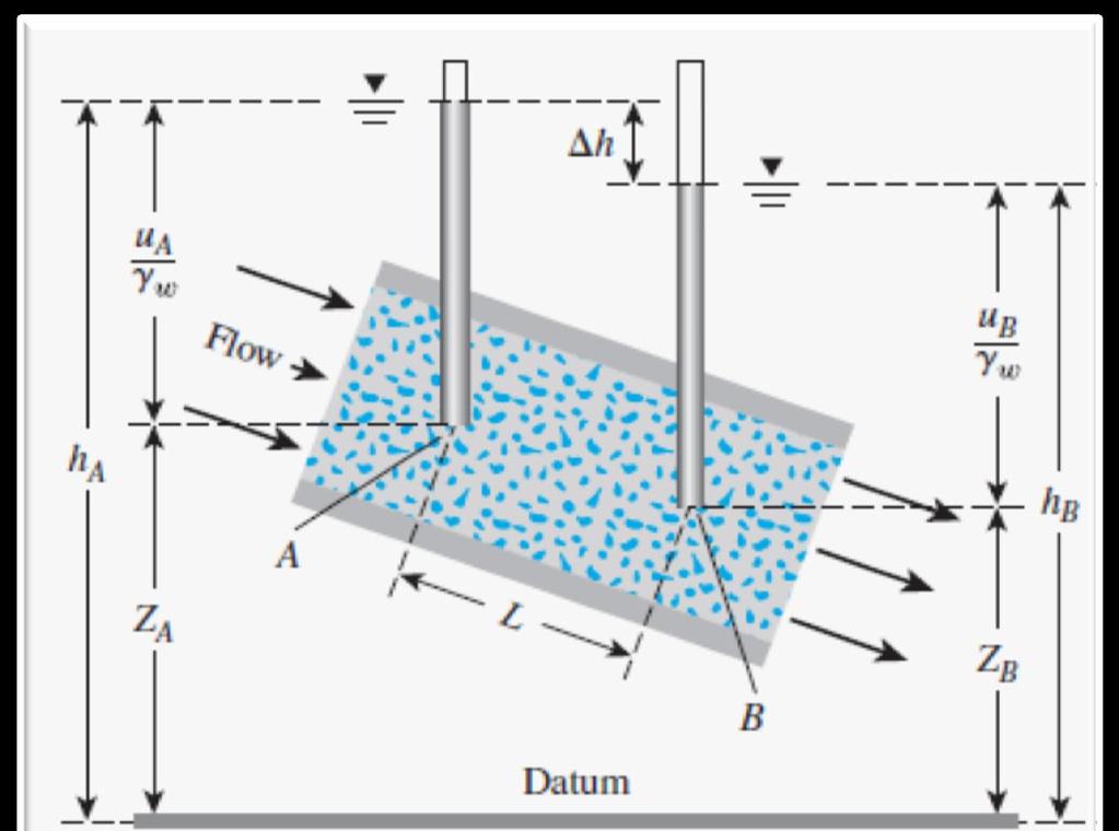
8 Hydraulic gradient(i) Total head loss per unit length between A and B i TH A l AB TH B water length AB, along the stream line A B

9 Hydraulic Gradient i h L
10 Bernoulli s Equation The energy of a fluid particle is made of: 1. Kinetic energy fluid particle - due to velocity 2. Strain energy z - due to pressure 3. Potential energy datum - due to elevation (z) with respect to a datum 10
11 Bernoulli s Equation If the equation is applied to the flow of water through porous soil medium, the term containing the velocity head can be neglected since the seepage velocity is small. Velocity head + 0 fluid particle Total head = Pressure head + z Elevation head datum Total head = Pressure head + Elevation head 11 1/29/2017
12 Bernoulli s equation u H γ v 2 2g z Total Head Pressure Head Dynamic Head Elevation Head H: total head P: water pressure γ: unit weight of water v: velocity of water g: gravity acceleration Z: elevation head
 can be neglected.")
13 Bernoulli s equation The seepage flow velocity in soil is very small. Therefore, the dynamic head (velocity head) can be neglected. So that the total head at any points is: u H z γ
14
15
 Hydraulic Conductivity")
16 Darcy s Law v i v - k i Negative sign refers to the hydraulic gradient that is negative. (i.e. total head decreases in the direction of flow) Hydraulic Conductivity

")
17 Darcy s Law Darcy (1856) found an equation for the discharge velocity of water through saturated soils: v = k i Permeability or hydraulic conductivity unit of velocity (cm/s) 17 1/29/2017
18 Permeability Values (cm/s) clays silts sands gravels Fines Coarse For coarse grain soils, k = f (e or D 10 ) 18 1/29/2017
19 Flow Rate Darcy s Velocity L Flow Rate v - k i q - k i A A q
20 Hydraulic Conductivity Typical Values for Hydraulic Conductivity Soil cm/s


21 Seepage Velocity (True Velocity) Seepage Velocity v s v n
22 Hydraulic Conductivity Hydraulic conductivity of soils depends on several factors: Fluid viscosity Pore size distribution Grain size distribution Void ratio Degree of soil saturation
23 Hydraulic Conductivity k γ w η γ w η K = Unit weight of water = Viscosity of water K = Absolute permeability (L 2 )

24 Hydraulic Conductivity with Temp.
25 Determination of Coefficient of Permeability There are 2 standard types of laboratory tests for determining the coefficient of permeability of soils: Constant head test Falling head test 25 1/29/2017
26 Determination of Coefficient of Permeability There are 2 standard types of laboratory tests for determining the coefficient of permeability of soils: Constant head test Falling head test 1/29/


27 Determination of Hydraulic Conductivity in the Lab Constant Head Test Falling Head Test

28 Constant Head Permeameter Most suitable for coarse grained soils, that have high k : 28 1/29/2017

29 Constant Head Test V V q t v A t V - k i A t h V - k A t L k V L A t h
30 Constant Head Permeameter The total volume of water collected is: Q Avt A( ki) t Where, Q: volume of water collected A: area of cross section of the soil sample t: duration of collection of water H h h QL i Q A( k ) t k l l l Aht 30 1/29/2017
31 Falling Head Permeameter Suitable for fine-grained soils with low k : 31 1/29/2017

32 Falling Head Test
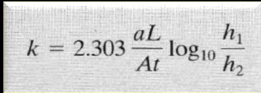
33 Falling Head Permeameter h dh q kia k A a L dt Where; q: rate of flow a: cross sectional area of the standpipe A: cross sectional area of the soil sample k al ln h al log h 1 33 At h 2 At h 2 1/29/2017
34
35
36
37
38

39
40

41 41
42 42
43 43


44 Equivalent Hydraulic Conductivity Case I: Horizontal Flow v 1 v2 v3 v vn
45 Equivalent Hydraulic Conductivity Case I: Horizontal Flow

46 Equivalent Hydraulic Conductivity Case II: Vertical Flow v

47 Equivalent Hydraulic Case II: Vertical Flow Conductivity
48

49

50
51 51
52 52
53
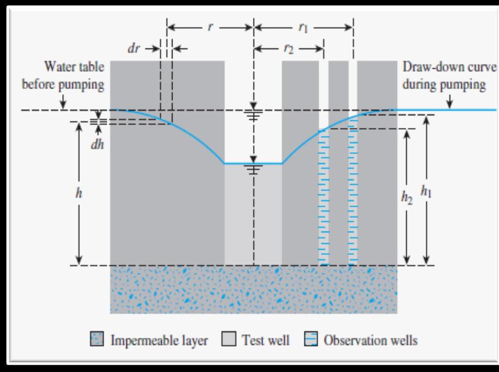
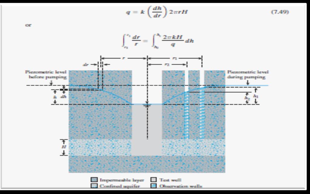
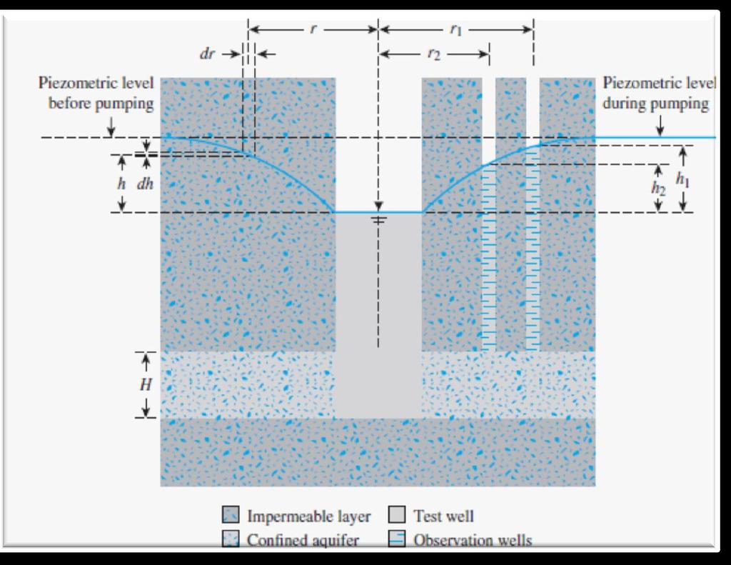
54 Pumped well in confined aquifer Elevation Aquifer heads pumped well Observation well H D Plan Radial flow Impermeable stratum aquifer
55 Pumped well in confined aquifer Elevation Aquifer heads pumped well Observation well H D Plan Radial flow Impermeable stratum aquifer

56
57
58 Permeability & Seepage 58 1/29/2017
59 Seepage Terminology concrete dam h L datum TH = h L TH = 0 soil 59 impervious strata 1/29/2017
60 Seepage Terminology Equipotential line is simply a contour of constant total head. h L concrete dam datum TH = h L TH = 0 TH=0.8 h L soil 60 impervious strata 1/29/2017
61 Stresses due to Flow Static Situation (No flow) h w L z X At X, v = w h w + sat z soil u = w (h w + z) v ' = ' z 61 1/29/2017
62 S t r e s s e s due to F l o w D o w n w a r d F l o w At X, v = w h w + sat z 62 as for static case u = w h w + w (L-h L )(z/l) = w h w + w (z-iz) = w (h w + z ) - w iz Reduction due to flow v ' = ' z + w iz Increase due to flow h h w u = L w h w z L X soil f l o w u = w (h w +L-h L ) 1/29/2017
63 Upward Flow At X, Stresses due to Flow flow v = w h w + sat z as for static case h L u = w h w + w (L+h L )(z/l) = w h w + w (z+iz) = w (h w +z) + w iz Increase due to flow v ' = ' z - w iz h w L z X soil u = w h w u = w (h w +L+h L ) 63 Reduction due to flow 1/29/2017
64 Flow nets Flow nets are useful in the study of seepage through porous media. A flow net consists of 2 sets of lines which for an isotropic (having equal properties in all directions) material are mutually perpendicular. 64 1/29/2017
65 Flow nets Lines drawn in the direction of flow are called flow lines (Ѱ-lines) Those perpendicular to the flow lines are called equipotential lines (Φ-lines) 65 1/29/2017
66 Seepage Terminology Stream line is simply the path of a water molecule. From upstream to downstream, total head steadily decreases along the stream line. h L TH = h L concrete dam datum TH = 0 soil 66 impervious strata 1/29/2017
67 Seepage Terminology Equipotential line is simply a contour of constant total head. h L concrete dam datum TH = h L TH = 0 TH=0.8 h L soil 67 impervious strata 1/29/2017
68 Flow net A network of selected stream lines and equipotential lines. concrete dam curvilinear square 90º soil 68 impervious strata 1/29/2017
69 Sketching of Flow Nets For practical purposes, flow nets can be obtained by sketching. The boundary conditions must be satisfied. An impermeable surface represents a flow line The interface between water and a porous medium is an equipotential line. 69 1/29/2017
70 Sketching of Flow Nets The procedure is: Draw geometry of the problem to a CHOSEN SCALE Prepare a first sketch of flow net trying to form equal sided figures and satisfying the boundary conditions Prepare an improved new sketch of flow net Correct the second sketch locally!!!example!!! 70 1/29/2017
71 Calculation of Seepage Loss through or beneath dams Let : Nd : Total number of equal drops in head Nf : Total number of flow channels Dl : side of a typical square of the flownet k : coefficient of permeability h : total drop in head between first and last lines 71 1/29/2017
72 Quantity of Seepage (Q) Q kh N f L Nd # of flow channels.per unit length normal to the plane # of equipotential drops h L concrete dam head loss from upstream to downstream 72 impervious strata 1/29/2017
73 Heads at a Point X Total head = h L - # of drops from upstream x h Elevation head = -z Pressure head = Total head Elevation head h N L d datum TH = h L TH = 0 concrete dam z h L h X 73 impervious strata 1/29/2017
74 Piping in Granular Soils At the downstream, near the dam, the exit hydraulic gradient i exit h l h L concrete dam l datum h = total head drop soil 74 impervious strata 1/29/2017
75 Piping in Granular Soils If i exit exceeds the critical hydraulic gradient (i c ), firstly the soil grains at exit get washed away. This phenomenon progresses towards the upstream, forming a free passage of water ( pipe ). h L concrete dam datum no soil; all water 75 impervious strata soil 1/29/2017
76 Piping in Granular Soils Piping is a very serious problem. It leads to downstream flooding which can result in loss of lives. Therefore, provide adequate safety factor against piping. F piping i i c exit concrete dam typically impervious strata soil 1/29/2017

77 Piping Failures Baldwin Hills Dam after it failed by piping in The failure occurred when a concentrated leak developed along a crack in the embankment, eroding the embankment fill and forming this crevasse. An alarm was raised about four hours before the failure and thousands of people were evacuated from the area below the dam. The flood that resulted when the dam failed and the reservoir was released caused several millions of dollars in damage. 77 1/29/2017
")
78 Piping Failures 78 Fontenelle Dam, USA (1965) 1/29/2017
79 Quick condition When flow is in the upward direction an unstable quick condition or boiling occurs when the upward seepage force per unit volume reaches the submerged unit weight of the soil. This condition usually occurs in sands. Determination of submerged unit weight of soil is needed by using the mass-volume relationships. (Lecture 1) 79 1/29/2017
80 Quick Condition in Granular Soils During upward flow, at X: v ' = ' z - w iz w z ' w i Critical hydraulic gradient (i c ) If i > i c, the effective stresses is negative. i.e., no inter-granular contact & thus failure. - Quick condition flow h L h w z L X soil 80 1/29/2017
81 Trench supported by sheet piles 5m 6m 6m 6m Uniform sand Impermeable clay
82 Trench supported by sheet piles 5m 6m 6m 6m Uniform sand Impermeable clay
83 Trench supported by sheet piles 5m 6m h=6m Nh=10 Nf= m 6m Uniform sand Impermeable clay
84 Excavation supported by a sheet pile Steel sheet Water pumped away Uniform sand Shale
85 Excavation supported by a sheet pile Steel sheet Water pumped away Uniform sand Shale
86 Reduced sheet penetration; possible liquefaction v = 0 Steel sheet Uniform sand Shale
87 Reduced sheet penetration; possible liquefaction v = 0 Reservoir Tail water Uniform sand Shale
88 Concrete dam or weir Reservoir Tail water Uniform sand Shale
89 Concrete dam with cut-off; reduces uplift pressure Reservoir Uniform sand Shale
90 Concrete dam with cut-off; reduces uplift pressure Reservoir Uniform sand Shale
91 Pumped well in confined aquifer Elevation Aquifer heads pumped well Observation well H D Plan Radial flow Impermeable stratum aquifer
92 Pumped well in confined aquifer Elevation Aquifer heads pumped well Observation well H D Plan Radial flow Impermeable stratum aquifer
93 Clay dam, no air entry reservoir atmospheric line drain clay Shale
94 Clay dam, no air entry atmospheric line reservoir drain clay Shale
95 Clay dam, no air entry Observation well atmospheric line reservoir drain clay Shale
96 Clay dam, no air entry, reduced drain; seepage out of downstream face reservoir atmospheric line Not possible clay Shale
97 Clay dam, with air entry reservoir drain clay Shale
98 Clay dam, with air entry reservoir drain clay Shale
99 Clay dam, no capillary, reduced drain; seepage out of downstream face reservoir clay Shale
100 Clay dam, no capillary, reduced drain; seepage out of downstream face reservoir clay Shale
101 Flow of water in earth dams The drain in a rolled clay dam will be made of gravel, which has an effectively infinite hydraulic conductivity compared to that of the clay, so far a finite quantity of flow in the drain and a finite area of drain the hydraulic gradient is effectively zero, i.e. the drain is an equipotential
102 Flow of water in earth dams The phreatic surface connects points at which the pressure head is zero. Above the phreatic surface the soil is in suction, so we can see how much capillarity is needed for the material to be saturated. If there is insufficient capillarity, we might discard the solution and try again. Alternatively: assume there is zero capillarity, the top water boundary is now atmospheric so along it and the flow net has to be adjusted within an unknown top boundary as the phreatic surface is a flow line if there is no capillarity.
103 Flow of water in earth dams If h y then h y cons in the flow net, so once we have the phreatic surface we can put on the starting points of the equipotentials on the phreatic surface directly
104 Unsteady flow effects Consolidation of matrix Change in pressure head within the soil due to changes in the boundary water levels may cause soil to deform, especially in compressible clays. The soil may undergo consolidation, a process in which the voids ratio changes over time at a rate determined by the pressure variation and the hydraulic conductivity, which may in turn depend on the voids ratio.
105 Breakdown of rigid matrix Liquefaction (tensile failure) The total stress normal to a plane in the soil can be separated into two components, the pore pressure p and the effective inter-granular stress : By convention in soils compressive stresses are +ve. Tensile failure occurs when the effective stress is less than the fracture strength fracture, and by definition for soil fracture=0. When the effective stress falls to zero the soil particles are no longer in contact with each other and the soil acts like a heavy liquid. This phenomenon is called liquefaction, and is responsible to quick sands. p
106 Large upward hydraulic gradients: Uniform soil of unit weight Upward flow of water
107 standpipe Water table and datum Critical head Pressure hcrit Critical potential Head h h z crit crit z Plug of Base area A Uniform soil of unit weight Gap opening as plug rises Upward flow of water
108 At the base of the rising plug, if there is no side friction: v p. z h crit. w So if v =0 then v = p and :. z h. h z. crit w crit w i crit h crit z w w, icrit=0.8~1.0
109 where icrit is the critical hydraulic gradient for the quick sand Condition. As 18~20 kn/m 3 for many soils (especially sands and silts) and w 10 kn/m 3 : i crit h z crit
110 Frictional (shear failure) Sliding failure of a gravity concrete dam due to insufficient friction along the base:
111 Reservoir H 1 W Tail water H 2 U p. ds W Uniform sand
112 Stresses due to Flow Static Situation (No flow) h w L z X At X, v = w h w + sat z soil u = w (h w + z) v ' = ' z 112 1/29/2017
113 S t r e s s e s due to F l o w D o w n w a r d F l o w At X, v = w h w + sat z 11 3 as for static case u = w h w + w (L-h L )(z/l) = w h w + w (z- i z ) = w (h w + z ) - w iz Reduction due to flow v ' = ' z + w iz Increase due to flow h h w u = L w h w z L X soil f l o w u = w (h w +L-h L ) 1/29/2017
114 Upward Flow At X, Stresses due to Flow flow v = w h w + sat z as for static case h L u = w h w + w (L+h L )(z/l) = w h w + w (z+iz) = w (h w +z) + w iz Increase due to flow v ' = ' z - w iz h w L z X soil u = w h w u = w (h w +L+h L ) 114 Reduction due to flow 1/29/2017
*** ***! " " ) * % )!( & ' % # $. 0 1 %./ +, - 7 : %8% 9 ) 7 / ( * 7 : %8% 9 < ;14. " > /' ;-,=. / ١
 * % )!( & ' % # $. 0 1 %./ +, - 7 : %8% 9 ) 7 / ( * 7 : %8% 9 < ;14. > /' ;-,=. / ١") ١ ******!" #$ % & '!( ) % * ") +,-./ % 01. 3 ( 4 56 7/4 ) 8%9 % : 7 ;14 < 8%9 % : *7./ = ;-, >/'." Soil Permeability & Seepage ٢ Soil Permeability- Definition ٣ What is Permeability? Permeability is the
١ ******!" #$ % & '!( ) % * ") +,-./ % 01. 3 ( 4 56 7/4 ) 8%9 % : 7 ;14 < 8%9 % : *7./ = ;-, >/'." Soil Permeability & Seepage ٢ Soil Permeability- Definition ٣ What is Permeability? Permeability is the
Civil Engineering Department College of Engineering
 Civil Engineering Department College of Engineering Course: Soil Mechanics (CE 359) Lecturer: Dr. Frederick Owusu-Nimo FREQUENCY CE 260 Results (2013) 30 25 23 25 26 27 21 20 18 15 14 15 Civil Geological
Chapter 7 Permeability and Seepage
 Permeability and Seepage - N. Sivakugan (2005) 1 7.1 INTRODUCTION Chapter 7 Permeability and Seepage Permeability, as the name implies (ability to permeate), is a measure of how easily a fluid can flow
Prof. B V S Viswanadham, Department of Civil Engineering, IIT Bombay
 13 Permeability and Seepage -2 Conditions favourable for the formation quick sand Quick sand is not a type of sand but a flow condition occurring within a cohesion-less soil when its effective stress is
Water in Soil Sections in Craig
 Water in Soil Sections 2.1-2.6 in Craig Outlines Introduction Darcy s Law Volume of water flowing per unit time Measuring K in laboratory Seepage Theory Flow Net Introduction All soils are permeable materials,
Geo-E2010 Advanced Soil Mechanics L Wojciech Sołowski. 26 February 2017
 Geo-E2010 Advanced Soil Mechanics L Wojciech Sołowski 26 February 2017 Permeability, consolidation and seepage Department of Civil Engineering Advanced Soil Mechanics W. Sołowski 2 To learn 1. What is
(Refer Slide Time: 02:10)
") Soil Mechanics Prof. B.V.S. Viswanathan Department of Civil Engineering Indian Institute of Technology, Bombay Lecture 24 Flow of water through soils-v Welcome to lecture five of flow of water through
Soil Mechanics Prof. B.V.S. Viswanathan Department of Civil Engineering Indian Institute of Technology, Bombay Lecture 24 Flow of water through soils-v Welcome to lecture five of flow of water through
b) EFFECTIVE STRESS (c) SEEPAGE
 EFFECTIVE STRESS (c) SEEPAGE") b) EFFECTIVE STRESS B1. A fine sand layer of 5 m thickness lies on a 5 m clay deposit. The water table is at the ground surface. Below the clay is a rock formation. Piezometers installed in the rock show
b) EFFECTIVE STRESS B1. A fine sand layer of 5 m thickness lies on a 5 m clay deposit. The water table is at the ground surface. Below the clay is a rock formation. Piezometers installed in the rock show
GEOTECHNICAL ENGINEERING II (Subject Code: 06CV64) UNIT 4: FLOW NETS 4.1 Introduction
 UNIT 4: FLOW NETS 4.1 Introduction") GEOTECHNICAL ENGINEERING II (Subject Code: 06CV64) UNIT 4: FLOW NETS 4.1 Introduction In this chapter the topics that are covered include principles of seepage analysis, graphical solutions for seepage
GEOTECHNICAL ENGINEERING II (Subject Code: 06CV64) UNIT 4: FLOW NETS 4.1 Introduction In this chapter the topics that are covered include principles of seepage analysis, graphical solutions for seepage
GEOTECHNICAL LABORATORY
 14.333 GEOTECHNICAL LABORATORY BERNOULLI S EQUATION h u w v 2 2g Z h = Total Head u = Pressure v = Velocity g = Acceleration due to Gravity w = Unit Weight of Water Slide 1 of 14 h 14.333 GEOTECHNICAL
VALLIAMMAI ENGINEERING COLLEGE
 VALLIAMMAI ENGINEERING COLLEGE DEPARTMENT OF CIVIL ENGINEERING SUBJECT CODE : CE6405 YEAR : II SUBJECT NAME : SOIL MECHANICS SEM : IV QUESTION BANK (As per Anna University 2013 regulation) UNIT 1- SOIL
ADVANCED SOIL MECHANICS
 BERNOULLI S EQUATION h Where: u w g Z h = Total Head u = Pressure = Velocity g = Acceleration due to Graity w = Unit Weight of Water h 14.531 ADVANCED SOIL MECHANICS BERNOULLI S EQUATION IN SOIL u w g
5. TWO-DIMENSIONAL FLOW OF WATER THROUGH SOILS 5.1 INTRODUCTION
 5. TWO-DIMENSIONAL FLOW OF WATER TROUG SOILS 5.1 INTRODUCTION In many instances the flo of ater through soils is neither one-dimensional nor uniform over the area perpendicular to flo. It is often necessary
 QUESTION BANK DEPARTMENT: CIVIL SUBJECT CODE / Name: CE 2251 / SOIL MECHANICS SEMESTER: IV UNIT 1- INTRODUCTION PART - A (2 marks) 1. Distinguish between Residual and Transported soil. (AUC May/June 2012)
Table of Contents Chapter 1 Introduction to Geotechnical Engineering 1.1 Geotechnical Engineering 1.2 The Unique Nature of Soil and Rock Materials
 Table of Contents Chapter 1 Introduction to Geotechnical Engineering 1.1 Geotechnical Engineering 1.2 The Unique Nature of Soil and Rock Materials 1.3 Scope of This Book 1.4 Historical Development of Geotechnical
Module 2 Lecture 9 Permeability and Seepage -5 Topics
 Module 2 Lecture 9 Permeability and Seepage -5 Topics 1.2.7 Numerical Analysis of Seepage 1.2.8 Seepage Force per Unit Volume of Soil Mass 1.2.9 Safety of Hydraulic Structures against Piping 1.2.10 Calculation
Permeability in Soils
 Permeability in Soils Contents: Darcy s law- assumption and validity, coefficient of permeability and its determination (laboratory and field), factors affecting permeability, permeability of stratified
Introduction to Soil Mechanics
 Introduction to Soil Mechanics Sela Sode and Colin Jones WILEY Blackwell Contents Preface Dedication and Acknowledgments List of Symbols Soil Structure 1.1 Volume relationships 1.1.1 Voids ratio (e) 1.1.2
All soils in natural are permeable materials, water being free to flow through the interconnected pores between the solid particles.
 8.1 Introduction Among construction materials, soil is very unique. Because of a relatively large space of void in its constituent, water can flow through soil. The water flow (seepage) characteristics
Soil Mechanics I 3 Water in Soils. 1. Capillarity, swelling 2. Seepage 3. Measurement of hydraulic conductivity 4. Effective stress in the ground
 Soil Mechanics I 3 Water in Soils 1. Capillarity, swelling 2. Seepage 3. Measurement of hydraulic conductivity 4. Effective stress in the ground 1 Influence of Water - Basics WATER IN SOIL - affects soil
ADVANCED SOIL MECHANICS FINAL EXAM (TAKE HOME):DUE THURSDAY, DECEMBER 19, 6PM.
:DUE THURSDAY, DECEMBER 19, 6PM.") 14.531 ADVANCED SOIL MECHANICS FINAL EXAM (TAKE HOME):DUE THURSDAY, DECEMBER 19, 2013 @ 6PM. Problem #1. Field load tests on strip footings yielded the test data provided below in Figure 1 and Table 1
14.531 ADVANCED SOIL MECHANICS FINAL EXAM (TAKE HOME):DUE THURSDAY, DECEMBER 19, 2013 @ 6PM. Problem #1. Field load tests on strip footings yielded the test data provided below in Figure 1 and Table 1
Distribution of pore water pressure in an earthen dam considering unsaturated-saturated seepage analysis
 E3S Web of Conferences 9, 194 (16) DOI: 1.11/ e3sconf/169194 E-UNSAT 16 Distribution of pore water in an earthen dam considering unsaturated-saturated seepage analysis 1a Kumar Venkatesh, Siva Ram Karumanchi
Theory of Shear Strength
 MAJ 1013 ADVANCED SOIL MECHANICS Theory of Shear Strength Prepared by, Dr. Hetty 1 Strength of different materials Steel Concrete Soil Tensile strength Compressive strength Shear strength Complex behavior
Chapter (12) Instructor : Dr. Jehad Hamad
 Instructor : Dr. Jehad Hamad") Chapter (12) Instructor : Dr. Jehad Hamad 2017-2016 Chapter Outlines Shear strength in soils Direct shear test Unconfined Compression Test Tri-axial Test Shear Strength The strength of a material is the
Chapter (12) Instructor : Dr. Jehad Hamad 2017-2016 Chapter Outlines Shear strength in soils Direct shear test Unconfined Compression Test Tri-axial Test Shear Strength The strength of a material is the
16 Rainfall on a Slope
 Rainfall on a Slope 16-1 16 Rainfall on a Slope 16.1 Problem Statement In this example, the stability of a generic slope is analyzed for two successive rainfall events of increasing intensity and decreasing
Course Scheme -UCE501: SOIL MECHANICS L T P Cr
 Course Scheme -UCE501: SOIL MECHANICS L T P Cr 3 1 2 4.5 Course Objective: To expose the students about the various index and engineering properties of soil. Introduction: Soil formation, various soil
Theory of Shear Strength
 SKAA 1713 SOIL MECHANICS Theory of Shear Strength Prepared by, Dr. Hetty 1 SOIL STRENGTH DEFINITION Shear strength of a soil is the maximum internal resistance to applied shearing forces The maximum or
Geotechnical Properties of Soil
 Geotechnical Properties of Soil 1 Soil Texture Particle size, shape and size distribution Coarse-textured (Gravel, Sand) Fine-textured (Silt, Clay) Visibility by the naked eye (0.05 mm is the approximate
A. V T = 1 B. Ms = 1 C. Vs = 1 D. Vv = 1
 Geology and Soil Mechanics 55401 /1A (2002-2003) Mark the best answer on the multiple choice answer sheet. 1. Soil mechanics is the application of hydraulics, geology and mechanics to problems relating
Geology and Soil Mechanics /1A ( ) Mark the best answer on the multiple choice answer sheet.
 Mark the best answer on the multiple choice answer sheet.") Geology and Soil Mechanics 55401 /1A (2003-2004) Mark the best answer on the multiple choice answer sheet. 1. Soil mechanics is the application of hydraulics, geology and mechanics to problems relating
Geology and Soil Mechanics 55401 /1A (2003-2004) Mark the best answer on the multiple choice answer sheet. 1. Soil mechanics is the application of hydraulics, geology and mechanics to problems relating
Prof. B V S Viswanadham, Department of Civil Engineering, IIT Bombay
 19 Module 5: Lecture -1 on Stability of Slopes Contents Stability analysis of a slope and finding critical slip surface; Sudden Draw down condition, effective stress and total stress analysis; Seismic
FUNDAMENTALS SOIL MECHANICS. Isao Ishibashi Hemanta Hazarika. >C\ CRC Press J Taylor & Francis Group. Taylor & Francis Group, an Informa business
 SOIL MECHANICS FUNDAMENTALS Isao Ishibashi Hemanta Hazarika >C\ CRC Press J Taylor & Francis Group Boca Raton London New York CRC Press is an imprint of the Taylor & Francis Group, an Informa business
PRINCIPLES OF GEOTECHNICAL ENGINEERING
 PRINCIPLES OF GEOTECHNICAL ENGINEERING Fourth Edition BRAJA M. DAS California State University, Sacramento I(T)P Boston Albany Bonn Cincinnati London Madrid Melbourne Mexico City New York Paris San Francisco
Seismic Stability of Tailings Dams, an Overview
 Seismic Stability of Tailings Dams, an Overview BY Gonzalo Castro, Ph.D., P.E. Principal International Workshop on Seismic Stability of Tailings Dams Case Western Reserve University, November 2003 Small
SOIL MECHANICS
 4.330 SOIL MECHANICS BERNOULLI S EQUATION Were: u w g Z = Total Head u = Pressure = Velocity g = Acceleration due to Graity w = Unit Weigt of Water Slide of 37 4.330 SOIL MECHANICS BERNOULLI S EQUATION
Lateral Earth Pressure
 1 of 11 6/2/2012 4:28 AM Lateral Earth Pressure The magnitude of lateral earth pressure depends on: 1. Shear strength characteristics of soil 2. Lateral strain condition 3. Pore water pressure 4. State
YOUR HW MUST BE STAPLED YOU MUST USE A PENCIL (no pens)
") Spring 2008 CIVE 462 HOMEWORK #1 1. Print out the syllabus. Read it. Write the grade percentages in the first page of your notes. 2. Go back to your 301 notes, internet, etc. and find the engineering definition
Spring 2008 CIVE 462 HOMEWORK #1 1. Print out the syllabus. Read it. Write the grade percentages in the first page of your notes. 2. Go back to your 301 notes, internet, etc. and find the engineering definition
Darcy's Law. Laboratory 2 HWR 531/431
 Darcy's Law Laboratory HWR 531/431-1 Introduction In 1856, Henry Darcy, a French hydraulic engineer, published a report in which he described a series of experiments he had performed in an attempt to quantify
The process of consolidation and settlement
 Consolidation Based on part of the GeotechniCAL reference package by Prof. John Atkinson, City University, London The process of consolidation and settlement One-dimensional consolidation theory The oedometer
PROBLEMS AND SOLUTIONS THAT MAY EMERGE IN THE FOUNDATION AND BODY OF A HOMOGENEOUS FILL DAM ON A WEAK CLAYEY-SILTY-SANDY FORMATION ÇIKRIKÇI DAM
 PROBLEMS AND SOLUTIONS THAT MAY EMERGE IN THE FOUNDATION AND BODY OF A HOMOGENEOUS FILL DAM ON A WEAK CLAYEY-SILTY-SANDY FORMATION ÇIKRIKÇI DAM Esen Yalım KARADUMAN BAR-SU Eng. & Conc. Inc. Ankara Turkey
Soil Mechanics Permeability of Soils and Seepage page 1 CHAPITRE 9. PERMEABILITY OF SOILS AND SEEPAGE...1
 Soil Mechanics Permeability of Soils and Seepage page 1 Contents of this chapter : CHAPITRE 9. PERMEABILITY OF SOILS AND SEEPAGE...1 9.1 INTRODUCTION...1 9.2 DARCY S LAW...1 9.2.1 DEFINITION OF HEAD...1
(Refer Slide Time: 01:15)
") Soil Mechanics Prof. B.V.S. Viswanathan Department of Civil Engineering Indian Institute of Technology, Bombay Lecture 56 Stability analysis of slopes II Welcome to lecture two on stability analysis of
Soil Mechanics Prof. B.V.S. Viswanathan Department of Civil Engineering Indian Institute of Technology, Bombay Lecture 56 Stability analysis of slopes II Welcome to lecture two on stability analysis of
Ch 4a Stress, Strain and Shearing
 Ch. 4a - Stress, Strain, Shearing Page 1 Ch 4a Stress, Strain and Shearing Reading Assignment Ch. 4a Lecture Notes Sections 4.1-4.3 (Salgado) Other Materials Handout 4 Homework Assignment 3 Problems 4-13,
Unsaturated Flow (brief lecture)
") Physical Hydrogeology Unsaturated Flow (brief lecture) Why study the unsaturated zone? Evapotranspiration Infiltration Toxic Waste Leak Irrigation UNSATURATAED ZONE Aquifer Important to: Agriculture (most
Physical Hydrogeology Unsaturated Flow (brief lecture) Why study the unsaturated zone? Evapotranspiration Infiltration Toxic Waste Leak Irrigation UNSATURATAED ZONE Aquifer Important to: Agriculture (most
Slope Stability. loader
 Slope Stability Slope Stability loader Lower San Fernando Dam Failure, 1971 Outlines Introduction Definition of key terms Some types of slope failure Some causes of slope failure Shear Strength of Soils
Micro-scale modelling of internally
 Micro-scale modelling of internally unstable soils Dr Tom Shire School of Engineering, University of Glasgow 1 st September 2017 Outline Internal instability Micro-scale modelling Hydromechanical criteria
CE 4780 Hurricane Engineering II. Section on Flooding Protection: Earth Retaining Structures and Slope Stability. Table of Content
 CE 4780 Hurricane Engineering II Section on Flooding Protection: Earth Retaining Structures and Slope Stability Dante Fratta Fall 00 Table of Content Introduction Shear Strength of Soils Seepage nalysis
5. Which surface soil type has the slowest permeability rate and is most likely to produce flooding? A) pebbles B) sand C) silt D) clay A) B) C) D)
 pebbles B) sand C) silt D) clay A) B) C) D)") 1. During a heavy rainstorm, soil samples A and B both became saturated with water. However, 10 minutes after the storm ended, the soils appeared as shown below. Which statement best explains the observed
1. During a heavy rainstorm, soil samples A and B both became saturated with water. However, 10 minutes after the storm ended, the soils appeared as shown below. Which statement best explains the observed
Tikrit University. College of Engineering Civil engineering Department CONSOILDATION. Soil Mechanics. 3 rd Class Lecture notes Up Copyrights 2016
 Tikrit University CONSOILDATION College of Engineering Civil engineering Department Soil Mechanics 3 rd Class Lecture notes Up Copyrights 2016 Stresses at a point in a soil mass are divided into two main
PERENNIAL PROBLEM OF EARTHEN BUND OF WELLINGDON RESERVOIR. ANALYSIS OF CAUSES AND REMEDIAL MEASURES A CASE STUDY.
 PERENNIAL PROBLEM OF EARTHEN BUND OF WELLINGDON RESERVOIR. ANALYSIS OF CAUSES AND REMEDIAL MEASURES A CASE STUDY. By Er. S. Muthu Parvatha Vardhini, Asst. Executive Engineer, (Designs) Water Resources
Chapter 1 - Soil Mechanics Review Part A
 Chapter 1 - Soil Mechanics Review Part A 1.1 Introduction Geotechnical Engineer is concerned with predicting / controlling Failure/Stability Deformations Influence of water (Seepage etc.) Soil behavour
Liquefaction is the sudden loss of shear strength of a saturated sediment due to earthquake shaking. Nisqually earthquake 02/28/2001: Olympia, WA
 Liquefaction is the sudden loss of shear strength of a saturated sediment due to earthquake shaking Nisqually earthquake 02/28/2001: Olympia, WA The shear strength is controlled by the degree of grain-to-grain
Seepage Analysis for Shurijeh Reservoir Dam Using Finite Element Method. S. Soleymani 1, A. Akhtarpur 2
 Seepage Analysis for Shurijeh Reservoir Dam Using Finite Element Method S. Soleymani 1, A. Akhtarpur 2 1 Group of Dam Construction, Toossab Company, P.O. Box 917751569, Mashhad City, Iran, PH (+98) 511-7684091;
International Journal of Scientific & Engineering Research, Volume 6, Issue 10, October ISSN
 International Journal of Scientific & Engineering Research, Volume 6, Issue 10, October-2015 30 Simulations of Seepage Flows in Dam Subjected to Varying Phretic Levels *Oladipupo S.OLADEJO and Umaru A.NDATSU
Prof. B V S Viswanadham, Department of Civil Engineering, IIT Bombay
 56 Module 4: Lecture 7 on Stress-strain relationship and Shear strength of soils Contents Stress state, Mohr s circle analysis and Pole, Principal stressspace, Stress pathsin p-q space; Mohr-Coulomb failure
1.5 Permeability Tests
 1-17 1.5 Permeability Tests 1.5.1 General - To determine the coefficient of permeability(or coefficient of hydraulic conductivity) k - General method for determining k directly. 1) Constant-head method
Soils. Technical English - I 10 th week
 Technical English - I 10 th week Soils Soil Mechanics is defined as the branch of engineering science which enables an engineer to know theoretically or experimentally the behavior of soil under the action
Principles of Foundation Engineering 8th Edition Das SOLUTIONS MANUAL
 Principles of Foundation Engineering 8th Edition SOLUTIONS MANUAL Full clear download (no formatting errors) at: https://testbankreal.com/download/principles-foundation-engineering- 8th-edition-das-solutions-manual/
DHANALAKSHMI COLLEGE OF ENGINEERING, CHENNAI DEPARTMENT OF CIVIL ENGINEERING CE6405 SOIL MECHANICS UNIT I : SOIL CLASSIFICATION AND COMPACTION
 DHANALAKSHMI COLLEGE OF ENGINEERING, CHENNAI DEPARTMENT OF CIVIL ENGINEERING CE6405 SOIL MECHANICS UNIT I : SOIL CLASSIFICATION AND COMPACTION PART A (2 marks) 1. Define Void ratio, Porosity and Degree
SEM-2016(01HI CIVIL ENGINEERING. Paper Answer all questions. Question No. 1 does not have internal choice,
 Roll No. Candidate should write his/her Roll No. here. Total No. of Questions : 5 No. of Printed Pages : 8 SEM-2016(01HI CIVIL ENGINEERING Paper - 11 Time : 3 Hours ] [ Total Marks : 300 Instructions to
Laboratory Testing Total & Effective Stress Analysis
 SKAA 1713 SOIL MECHANICS Laboratory Testing Total & Effective Stress Analysis Prepared by: Dr. Hetty Mohr Coulomb failure criterion with Mohr circle of stress 2 ' 2 ' ' ' 3 ' 1 ' 3 ' 1 Cot Sin c ' ' 2
SHEAR STRENGTH OF SOIL
 Soil Failure Criteria SHEAR STRENGTH OF SOIL Knowledge about the shear strength of soil important for the analysis of: Bearing capacity of foundations, Slope stability, Lateral pressure on retaining structures,
SHEAR STRENGTH OF SOIL
 SHEAR STRENGTH OF SOIL Necessity of studying Shear Strength of soils : Soil failure usually occurs in the form of shearing along internal surface within the soil. Shear Strength: Thus, structural strength
SOIL MECHANICS: palgrave. Principles and Practice. Graham Barnes. macmiiian THIRD EDITION
 SOIL MECHANICS: Principles and Practice THIRD EDITION Graham Barnes palgrave macmiiian 'running Contents Preface xii Fine soil 19 List of symbols xiv Mass structure 21 Note on units xix Degree of weathering
UNIT I FLUID PROPERTIES AND STATICS
 SIDDHARTH GROUP OF INSTITUTIONS :: PUTTUR Siddharth Nagar, Narayanavanam Road 517583 QUESTION BANK (DESCRIPTIVE) Subject with Code : Fluid Mechanics (16CE106) Year & Sem: II-B.Tech & I-Sem Course & Branch:
dynamics of f luids in porous media
 dynamics of f luids in porous media Jacob Bear Department of Civil Engineering Technion Israel Institute of Technology, Haifa DOVER PUBLICATIONS, INC. New York Contents Preface xvii CHAPTER 1 Introduction
GEOSYNTHETICS ENGINEERING: IN THEORY AND PRACTICE
 GEOSYNTHETICS ENGINEERING: IN THEORY AND PRACTICE Prof. J. N. Mandal Department of civil engineering, IIT Bombay, Powai, Mumbai 400076, India. Tel.022-25767328 email: cejnm@civil.iitb.ac.in Module - 4
Introduction to Geotechnical Engineering. ground
 Introduction to Geotechnical Engineering ground 1 Typical Geotechnical Project Geo-Laboratory ~ for testing soil properties Design Office ~ for design & analysis construction site 2 Shallow Foundations
SOIL SHEAR STRENGTH. Prepared by: Dr. Hetty Muhammad Azril Fauziah Kassim Norafida
 SOIL SHEAR STRENGTH Prepared by: Dr. Hetty Muhammad Azril Fauziah Kassim Norafida What is shear strength Shear strength of a soil is the maximum internal resistance to applied shearing forces Why it is
Landslide FE Stability Analysis
 Landslide FE Stability Analysis L. Kellezi Dept. of Geotechnical Engineering, GEO-Danish Geotechnical Institute, Denmark S. Allkja Altea & Geostudio 2000, Albania P. B. Hansen Dept. of Geotechnical Engineering,
COMPARISION OF HYDRAULIC GRADIENT AND UPLIFT PRESSURE IN THREE TYPES OF DAMS: HOMOGENEOUS, HETEROGENEOUS EARTHFILL DAMS AND CONCRETE GRAVITY DAM
 SAJCCE 1:1 (2015) 91-103 October 2015 ISSN: 2394-2258 Available at http://scientificadvances.co.in DOI: http://dx.doi.org/10.18642/sajcce_7100121544 COMPARISION OF HYDRAULIC GRADIENT AND UPLIFT PRESSURE
(Refer Slide Time: 02:18)
") Geology and Soil Mechanics Prof. P. Ghosh Department of Civil Engineering Indian Institute of Technology Kanpur Lecture 40 Shear Strength of Soil - C Keywords: Shear strength of soil, direct shear test,
Geology and Soil Mechanics Prof. P. Ghosh Department of Civil Engineering Indian Institute of Technology Kanpur Lecture 40 Shear Strength of Soil - C Keywords: Shear strength of soil, direct shear test,
Stability Analysis of Landslide Dam under Rainfall
 Stability Analysis of Landslide Dam under Rainfall Pei-Hsun Tsai, Zheng-Yi Feng 2, Fan-Chieh Yu 3 and Jian-Han Lin 4 Associate Professor, Department of Construction Engineering, Chaoyang University of
Principal Symbols. f. Skin friction G Shear modulus. Cu Coefficient of uniformity Cc Coefficient of curvature
 Principal Symbols A, a Area A Air content A, A Pore pre.ssure coefficients a' Modified shear strength parameter (effective stress) a Dial gauge reading in oedometer test B Width of footing B, B Pore pressure
Earth dam steady state seepage analysis
 Engineering manual No. 32 Updated 3/2018 Earth dam steady state seepage analysis Program: FEM Water Flow File: Demo_manual_32.gmk Introduction This example illustrates an application of the GEO5 FEM module
International Journal of Scientific & Engineering Research, Volume 8, Issue 2, February ISSN
 P P International Journal of Scientific & Engineering Research, Volume 8, Issue 2, February-2017 1053 Effect of Impervious Core on Seepage through Zoned Earth Dam (Case Study: Khassa Chai Dam) Abstract
Soil Properties - I. Amit Prashant. Indian Institute of Technology Gandhinagar. Short Course on. Geotechnical Aspects of Earthquake Engineering
 Soil Properties - I Amit Prashant Indian Institute of Technology Gandhinagar Short Course on Geotechnical Aspects of Earthquake Engineering 04 08 March, 2013 Regional Soil Deposits of India Alluvial deposits
Design of RC Retaining Walls
 Lecture - 09 Design of RC Retaining Walls By: Prof Dr. Qaisar Ali Civil Engineering Department UET Peshawar www.drqaisarali.com 1 Topics Retaining Walls Terms Related to Retaining Walls Types of Retaining
Cyclic Triaxial Behavior of an Unsaturated Silty Soil Subjected to Suction Changes
 6 th International Conference on Earthquake Geotechnical Engineering 1-4 November 215 Christchurch, New Zealand Cyclic Triaxial Behavior of an Unsaturated Silty Soil Subjected to Suction Changes T. Nishimura
Intro to Soil Mechanics: the what, why & how. José E. Andrade, Caltech
 Intro to Soil Mechanics: the what, why & how José E. Andrade, Caltech The What? What is Soil Mechanics? erdbaumechanik The application of the laws of mechanics (physics) to soils as engineering materials
2017 Soil Mechanics II and Exercises Final Exam. 2017/7/26 (Wed) 10:00-12:00 Kyotsu 4 Lecture room
 10:00-12:00 Kyotsu 4 Lecture room") 2017 Soil Mechanics II and Exercises Final Exam 2017/7/26 (Wed) 10:00-12:00 Kyotsu 4 Lecture room Attention: The exam consists of five questions for which you are provided with five answer sheets. Write
2017 Soil Mechanics II and Exercises Final Exam 2017/7/26 (Wed) 10:00-12:00 Kyotsu 4 Lecture room Attention: The exam consists of five questions for which you are provided with five answer sheets. Write
Cubzac-les-Ponts Experimental Embankments on Soft Clay
 Cubzac-les-Ponts Experimental Embankments on Soft Clay 1 Introduction In the 197 s, a series of test embankments were constructed on soft clay at Cubzac-les-Ponts in France. These full-scale field tests
See discussions, stats, and author profiles for this publication at:
 See discussions, stats, and author profiles for this publication at: http://www.researchgate.net/publication/261179220 Analysis of Seepage Problem effects underneath Diyala Weir using 2-D model for the
We are IntechOpen, the world s leading publisher of Open Access books Built by scientists, for scientists. International authors and editors
 We are IntechOpen, the world s leading publisher of Open Access books Built by scientists, for scientists 3,500 108,000 1.7 M Open access books available International authors and editors Downloads Our
Practical methodology for inclusion of uplift and pore pressures in analysis of concrete dams
 Practical methodology for inclusion of uplift and pore pressures in analysis of concrete dams Michael McKay 1 and Francisco Lopez 2 1 Dams Engineer, GHD Pty 2 Principal Dams/Structural Engineer, GHD Pty
Advanced Hydrology Prof. Dr. Ashu Jain Department of Civil Engineering Indian Institute of Technology, Kanpur. Lecture 6
 Advanced Hydrology Prof. Dr. Ashu Jain Department of Civil Engineering Indian Institute of Technology, Kanpur Lecture 6 Good morning and welcome to the next lecture of this video course on Advanced Hydrology.
Chapter 5 Shear Strength of Soil
 Page 5 Chapter 5 Shear Strength of Soil. The internal resistance per unit area that the soil mass can offer to resist failure and sliding along any plane inside it is called (a) strength (b) shear strength
CE 240 Soil Mechanics & Foundations Lecture 5.2. Permeability III (Das, Ch. 6) Summary Soil Index Properties (Das, Ch. 2-6)
 Summary Soil Index Properties (Das, Ch. 2-6)") CE 40 Soil Mechanics & Foundations Lecture 5. Permeability III (Das, Ch. 6) Summary Soil Index Properties (Das, Ch. -6) Outline of this Lecture 1. Getting the in situ hydraulic conductivity 1.1 pumping
CE 40 Soil Mechanics & Foundations Lecture 5. Permeability III (Das, Ch. 6) Summary Soil Index Properties (Das, Ch. -6) Outline of this Lecture 1. Getting the in situ hydraulic conductivity 1.1 pumping
Chapter 2. 53% v. 2.2 a. From Eqs. (2.11) and (2.12), it can be seen that, 2.67
 and (2.12), it can be seen that, 2.67") Chapter 2 2.1 d. (87.5)(9.81) (1000)(0.05) 3 17.17 kn/m c. d 1 w 17.17 1 0.15 3 14.93 kn/m G a. Eq. (2.12): s w (2.68)(9.81). 14.93 ; e 0.76 1 e 1 e e 0.76 b. Eq. (2.6): n 0.43 1 e 1 0.76 Vw wgs (0.15)(2.68)
Chapter 2 2.1 d. (87.5)(9.81) (1000)(0.05) 3 17.17 kn/m c. d 1 w 17.17 1 0.15 3 14.93 kn/m G a. Eq. (2.12): s w (2.68)(9.81). 14.93 ; e 0.76 1 e 1 e e 0.76 b. Eq. (2.6): n 0.43 1 e 1 0.76 Vw wgs (0.15)(2.68)
- To determine the coefficient of permeability (or coefficient of hydraulic
 39 2.6 Permeability Tests 2.6.1 General - To determine te coefficient of permeability (or coefficient of ydraulic conductivity) k. - General metod for determining k directly. 1) Constant-ead metod (for
Seismic Design of a Hydraulic Fill Dam by Nonlinear Time History Method
 Seismic Design of a Hydraulic Fill Dam by Nonlinear Time History Method E. Yıldız & A.F. Gürdil Temelsu International Engineering Services Inc., Ankara, Turkey SUMMARY: Time history analyses conducted
Deep Foundations 2. Load Capacity of a Single Pile
 Deep Foundations 2 Load Capacity of a Single Pile All calculations of pile capacity are approximate because it is almost impossible to account for the variability of soil types and the differences in the
Changes in soil deformation and shear strength by internal erosion
 Changes in soil deformation and shear strength by internal erosion C. Chen & L. M. Zhang The Hong Kong University of Science and Technology, Hong Kong, China D. S. Chang AECOM Asia Company Ltd., Hong Kong,
FOUNDATION ENGINEERING UNIT V
 FOUNDATION ENGINEERING UNIT V RETAINING WALLS Plastic equilibrium in soils active and passive states Rankine s theory cohesion less and cohesive soil - Coloumb s wedge theory condition for critical failure
EARTH PRESSURES ON RETAINING STRUCTURES
 12-1 12. EARTH PRESSURES ON RETAINING STRUCTURES 12.1 Active Pressure and Passive Pressure When a sudden change in level of the ground surface is to be provided for some purpose a retaining structure is
Centrifuge modelling of municipal solid waste landfills under earthquake loading
 Centrifuge modelling of municipal solid waste landfills under earthquake loading N.I. Thusyanthan Ph.D research student, Schofield Centre, University of Cambridge, Cambridge, CB3 0EL, UK. Email: it206@cam.ac.uk
Effect of Location and Angle of Cutoff Wall on Uplift Pressure in Diversion Dam
 Geotech Geol Eng (2014) 32:1165 1173 DOI 10.1007/s10706-014-9774-3 ORIGINAL PAPER Effect of Location and Angle of Cutoff Wall on Uplift Pressure in Diversion Dam Behnam Mansuri Farzin Salmasi Behrooz Oghati
Triaxial Shear Test. o The most reliable method now available for determination of shear strength parameters.
 TOPICS Introduction Components of Shear Strength of Soils Normal and Shear Stresses on a Plane Mohr-Coulomb Failure Criterion Laboratory Shear Strength Testing Direct Shear Test Triaxial Compression Test
FE Fluids Review March 23, 2012 Steve Burian (Civil & Environmental Engineering)
") Topic: Fluid Properties 1. If 6 m 3 of oil weighs 47 kn, calculate its specific weight, density, and specific gravity. 2. 10.0 L of an incompressible liquid exert a force of 20 N at the earth s surface.
Topic: Fluid Properties 1. If 6 m 3 of oil weighs 47 kn, calculate its specific weight, density, and specific gravity. 2. 10.0 L of an incompressible liquid exert a force of 20 N at the earth s surface.
Hydraulic conductivity of granular materials
 3 r d International Conference on New Developments in Soil Mechanics and Geotechnical Engineering, Hydraulic conductivity of granular materials Namir K.S.Al-Saoudi Building and construction Eng. Dept.