APPENDIX 6: GEOTECHNICAL FEASIBILITY INVESTIGATION
|
|
|
- Archibald Atkinson
- 5 years ago
- Views:
Transcription
1 APPENDIX 6: GEOTECHNICAL FEASIBILITY INVESTIGATION

2 ENVIRONMENTAL SCIENCE ASSOCIATES SAMANCOR CHROME, MIDDELBURG GEOTECHNICAL FEASIBILITY INVESTIGATION FOR NEW CHROME PLANT FACILITY J VAN TONDER (PrSciNat) ENGINEERING GEOLOGIST DJ MOUTON (PrSciNat) DIRECTOR Prepared by: KNIGHT HALL HENDRY PO Box LYNNWOOD RIDGE 0040 Tel: Fax: jvantonder@knightpiesold.com KHH 1660 / 5266 OCTOBER 2007 JDC-JvT/5266 /KHH Rev.0 ( )
3 SAMANCOR CHROME, MIDDELBURG GEOTECHNICAL FEASIBILITY INVESTIGATION FOR NEW CHROME PLANT FACILITY TABLE OF CONTENTS 1. INTRODUCTION SITE DESCRIPTION METHOD OF INVESTIGATION GEOLOGY AND GROUND CONDITIONS... 2 Page 4.1 Geology and Weathering Soil Profile LABORATORY TEST RESULTS GEOTECHNICAL ASSESSMENT Plant Site Waste Disposal Construction Materials CONCLUSIONS AND RECOMMENDATIONS... 7 REFERENCES... 9 TABLES TABLE 1 : SUMMARY OF TEST PIT PROFILES TABLE 2A & 2B : SUMMARY OF LABORATORY TEST RESULTS ON SOIL SAMPLES FIGURES FIGURE 1 FIGURE 2 FIGURE 3 : LOCALITY PLAN : SITE LAYOUT WITH TEST PIT POSITIONS : BEDROCK TOPOGRAPHY APPENDICES APPENDIX A APPENDIX B APPENDIX C : GEOPHYSICAL SURVEY REPORT : TEST PIT PROFILES : LABORATORY TEST RESULTS OF SOIL SAMPLES
4 SAMANCOR CHROME, MIDDELBURG GEOTECHNICAL FEASIBILITY INVESTIGATION FOR NEW CHROME PLANT FACILITY 1. INTRODUCTION Knight Hall Hendry (KHH) was appointed by Mr. T Fischer of Environmental Science Associates to conduct a feasibility level geotechnical investigation for the proposed plant facility at Samancor Chrome, Middelburg. Previous investigations in close vicinity of the area were conducted by Knight Piésold in 1997, which entailed a hydrological investigation and groundwater modelling study for the dust disposal dam at Middelburg Ferrochrome [1] 1. The available ground for the construction of the new plant and waste disposal facility covers an area of approximately 1,2km by 0,6km. The objective of the feasibility level geotechnical investigation was to provide the geotechnical characteristics of the subsurface soils and underlying bedrock for planning and preliminary design purposes for the construction of the plant, particularly to optimally position the plant site and to ensure that possible sites for future waste disposal are identified at an early stage. This feasibility geotechnical investigation was conducted in two phases, namely Phase 1, which consisted of a reconnaissance walk-over site visit and geophysical studies comprising electric resistivity surveys, and Phase 2, which comprised testpitting across the site with an excavator. The purpose of the Phase 1 geophysical survey was to identify the best area for a plant site and to determine the depth of weathering of the underlying bedrock. Testpitting in Phase 2 confirmed the results of the electric resistivity surveys and also characterised the underlying soil and rock properties. Selected soil samples from representative soil horizons were taken during the testpitting phase to determine specific geotechnical soil properties. 2. SITE DESCRIPTION The site is located to the west of the Samancor industrial area, north of the N4 Highway. Access to the site is along a gravel road that runs from north to south past the western perimeter of the site. A borrow pit is located in the northern portion of the site along this gravel road, between an old landing strip and the gravel road. The existing dust disposal dam is located along the eastern perimeter of the site, and the area south towards the N4 Highway comprises open grassland. The site is covered by grass and sparse bush common to the Highveld regions with scattered exotic trees along the western gravel road. Drainage over the site takes place in a south-east direction towards the Vaalbank Spruit that runs north towards Middelburg town, where it flows into the Klein Olifants River. A series of water channels were previously installed across the site in a north-south direction to intercept any surface water draining towards the existing dust disposal dam to the east. 1 References are indicated thus and are listed at the back of the report. JDC-JvT/5266 /KHH Rev.0 ( )


5
6 KNIGHT HALL HENDRY 2 3. METHOD OF INVESTIGATION The geophysical survey was conducted during July 2007, and comprised seven traverses, which were positioned in a north-south and east-west direction to cover most of the study area. The detailed geophysical report and survey results are contained in Appendix A. Figure 2 provides the positions of the seven traverses, numbered A to G. Testpitting was performed on 1 to 3 August 2007 and entailed the excavation of 22 test pits (TP1 to TP22) with a 33 ton excavator, supplied by Samancor. Test pits were positioned according to the results of the geophysical survey to verify the weathering depths. All test pits were excavated into bedrock or to the maximum reach of the machine. Test pits were logged by an engineering geologist according to the recommended standard procedures [2]. Test pit logs are contained in Appendix B. Representative soil samples were taken for laboratory testing to determine soil particle size distribution and Atterberg Limits, compaction and strength characteristics, as well as the coefficients of permeability of the various soils. Refer to Appendix C for the laboratory test results. The co-ordinates of all test pit positions were recorded with a handheld GPS (accuracy of 5m), and are given on the individual test pit logs in WGS84 datum. The positions of all the test pits are indicated in Figure GEOLOGY AND GROUND CONDITIONS 4.1 Geology and Weathering According to the published 1 : scale geological map of the area, Sheet 2528 Pretoria, the site is situated on shale and quartzite of the Loskop Formation, Transvaal Supergroup. Testpitting revealed that most of the site is underlain by shale with quartzite present as interlayered bands in the soil profiles. Weathering on shale generally extends to considerable depth, producing thick surface cover which comprises silty clayey soil. Weathering of quartzite is usually limited to a shallower depth with only a thin soil cover, comprising silty sand. The sedimentary rock layers dip generally at 20º north to north-east. According to previous investigations the area south of the site should be underlain by dolerite, which weathers to clayey soils. The geophysical survey shows that intensive weathering occurs in the western and northern portions of the site, while the south-east portion is characterized by shallow rock. 4.2 Soil Profile A summary of the test pits profiles is provided in Table 1 at the back of this report. The area can be divided into three soil type zones, namely Zones A, B and C as indicated in Figure 2. Figure 3 provides depth-to-rock contours of the study area. The following generalized soil profile occurs in each zone: JDC-JvT/5266 /KHH Rev.0 ( )
7
8
9 KNIGHT HALL HENDRY 3 Zone A Zone A is characterised by deeply weathered soil profiles consisting of transported soils, nodular ferricrete and residual shale. Transported soils cover the area to a depth of between 0,3m and 1,8m. The south portion of Zone A is covered by topsoil to a depth of 0,4m comprising sandy silty clay of soft consistency. Hillwash covers the rest of the area to a depth of 1,8m and comprises gravelly silty sand to silty sandy gravel of loose to medium dense consistency. The soil structure varies from intact to pinholed. The transported soil layers are also ferruginised with depth. Nodular ferricrete occurs directly below the transported soil cover and comprises abundant ferricrete nodules in a silty clay/clayey sand matrix, which extends to depths of between 0,9m and 2,7m. Consistency varies from loose to dense and also very dense in TP6 where it occurs as honeycomb ferricrete to a depth of 2,7m. It is believed that the nodular ferricrete layer formed at the base of the transported soil layer and is in all instances underlain directly by residual shale soil or shale rock. Residual shale comprises slightly sandy silty clay with soft to firm consistencies becoming stiff and very stiff close to bedrock. The soil has an intact to relict jointed and layered structure with depth. Residual shale extends to depths of between 2,0m to more than 5,7m (maximum reach of excavator). Residual quartzite occurs in TP18 as loose to medium dense clayey silty sand from a depth of 3,2m. Quartzite bedrock occurs only in TP18 as completely to highly weathered very soft to soft rock from a depth of 5,4m. The quartzite occurs in a north-west striking band along the far northern portion of Zone A (also encountered in TP2 in Zone C), which was identified by the electric resistivity surveys as relatively resistant material. The soil profile in TP7 comprises interbedded layers of very soft to soft rock quartzite and shale between a depth of 1,4m and 4,2m. Shale bedrock occurs from a depth of between 2,0m and 3,3m as highly weathered very soft rock. In TP20 and TP21 shale bedrock was not encountered with residual shale extending deeper than 5,6m, i.e. the maximum reach of the excavator. It is apparent from Figure 3 that the depth to bedrock increases towards the north. The boundary between Zone A and Zone C is arbitrary, but TP20 and TP21 were grouped in Zone A because distinct ferruginisation occurs in the upper 1m of the soil profile, generally not encountered in Zone C. Zone B Zone B is characterised by shallow weathering comprising thin transported and residual shale layers. The area is covered by transported soil to a depth of between 0,3m and 1,1m. Topsoil occurs at TP5 and TP10 as slightly sandy silty clay of soft consistency. The rest of the area is covered by hillwash comprising clayey/silty sand with scattered gravel. The consistency is JDC-JvT/5266 /KHH Rev.0 ( )
10 KNIGHT HALL HENDRY 4 loose to medium dense and the soil structure is intact. At TP4 the transported soil is ferruginised to a depth of 1,1m. Ferricrete occurs at a shallow depth below the hillwash in TP5 and TP11 and comprises abundant ferricrete nodules in clayey sand/silt matrix of dense consistency. Residual shale generally occurs directly below the hillwash soil cover and comprises silty clay with abundant shale gravel, which extends to a depth of between 0,7m and 1,7m. In TP5 and TP13 the residual shale is ferruginised in the upper portion of the layer. Shale bedrock occurs at a relatively shallow depth of between 0,7m to 1,7m in Zone B. It generally comprises highly weathered very soft to soft rock and caused refusal, or very difficult excavation conditions, at a depth of between 1m and 1,5m. Zone C Zone C is characterised by deeply weathered profiles comprising a relatively thin transported soil cover and a thick residual shale layer. Transported soil covers the area to a depth of between 0,2m and 0,8m. Topsoil occurs in TP15 to TP17 as sandy silty clay of soft consistency. Hillwash covers the rest of the area and comprises gravelly silty sand of loose to medium dense consistency. Nodular ferricrete occurs only in TP14 as abundant ferricrete nodules in sandy clay matrix of soft consistency to a depth of 1,4m Residual shale occurs from a depth of between 0,2m and 1,4m and comprises slightly sandy silty clay becoming silty clay with depth. Consistency is generally firm, but becomes stiff with depth. The soil structure varies from intact to relict layered with depth. The soil profile in TP2 comprises residual shale of firm consistency, interlayered by bands of soft rock quartzite. Shale bedrock occurs from a depth of between 1,4m (east) and 4,8m (north-west) as highly weathered very soft to soft rock with depth. A perched water table was encountered over the site from depths ranging between 0,4m and 5,4m. 5. LABORATORY TEST RESULTS A summary of the laboratory test results is provided in Tables 2A and 2B at the back of the report. The results are discussed below. Transported soil (TP4) comprises silty gravelly sand with a low clay content of 7% and a low Plasticity Index (PI) of 11%. The soil has a low potential expansiveness. Nodular ferricrete comprises slightly clayey and silty sandy gravel with a clay content of 12% and a PI of 22%. The potential expansiveness is also low. The material has a maximum modified AASHTO dry density of 2076kg/m³. When compacted to 95% of Modified AASHTO maximum dry density at optimum moisture content, the coefficient of permeability of the ferricrete is 2,7 x 10⁻⁸ cm/s. JDC-JvT/5266 /KHH Rev.0 ( )
11 KNIGHT HALL HENDRY 5 Residual shale generally comprises slightly sandy silty clay to clayey silt, with clay contents ranging from 14% to 38% and PI values from 14% to 30%. The potential for expansiveness is generally medium to high. The in situ dry density of residual shale ranges between 1564kg/m³ and 1675kg/m³ with coefficients of permeability of undisturbed samples from 5 x 10⁻⁶ cm/s and 8 x 10⁻⁹ cm/s. The optimum modified AASHTO dry density of the residual shale ranges between 1830kg/m³ and 1970kg/m³ at moisture contents of between 11% and 15%. Residual shale compacted to 95% of Modified AASHTO maximum dry density at optimum moisture content renders coefficients of permeability of about 1 x 10⁻⁸ cm/s. The soaked shear box test on an undisturbed residual shale sample (TP3) renders a cohesion of 42kN/m 2 with an angle of internal friction of 26º. The same test on a recompacted (95% of Modified AASTHO maximum dry density) residual shale sample renders a cohesion of 13kN/m 2 with an angle of internal friction of 33º. A slake durability test was conducted on very soft rock shale encountered in TP3 at a depth of between 1,1m and 1,3m. The test results classify the durability as medium indicating a relatively low durability, which is typical for a mudrock. Chemical tests were conducted on groundwater samples collected from TP5 and TP10 to determine soil aggressiveness towards concrete and mild steel. The Basson indices were recorded. The test results rendered very high ph values of between 8,2 and 9,5 (TP10 and TP5 respectively). The final Basson aggressiveness index classifies the groundwater in TP10 as mildly to fairly aggressive, i.e. fairly corrosive towards concrete but highly corrosive towards metals. The final aggressiveness index of the groundwater in TP5 classifies as highly aggressive, although the individual dissolved solids of calcium, magnesium and sulphates are much lower than in TP GEOTECHNICAL ASSESSMENT 6.1 Plant Site The electrical resistivity survey results clearly differentiated between the south-east area underlain by shallow, relatively unweathered shale (Zone B) and the remainder of the site, which is characterised by deep weathering and relatively thick clayey soil profiles (Zones A and C). The presence of the quartzite bands and possible dyke intrusions were also identified. It provided a solid base for the testpitting and sampling components of the study. A remarkable good correlation was found between the results of the geophysical surveys and the test pits. The high resistive area is characterized by the shallow shale encountered in Zone B, while the majority of the study area is highly conductive and correlates with the presence of the clayey soil cover and deep weathering. Geophysical results identified a thin, resistant layer at surface along the western portion of the site, overlying highly conductive material. This was interpreted as the ferruginised/nodular ferricrete layer found in Zone A. Figure 3 clearly shows that Zone B offers the preferred area for a plant site. The depth to shale rock is generally less than 2m and the results of the electrical resistivity survey show that the unweathered shale layer extends to a depth of at least 25m. Results of the single durability test conducted on the weathered shale indicated 85% Slake Durability Index (Medium). It is therefore JDC-JvT/5266 /KHH Rev.0 ( )
12 KNIGHT HALL HENDRY 6 not considered necessary to provide special precautionary measures to protect the shale after exposure, although some dessicated cracking will appear in the shale if left open and unprotected for longer than say 3 to 4 days. It will therefore be advantageous to cover the rock in foundation excavations as soon as possible after final foundation preparations have been completed. Favourable foundations for the plant are thus present in Zone B due to the shallow bedrock, which is relatively consistent over the area. Bedrock, which is encountered at a depth of between 0,7m and 1,7m, comprises weathered, very soft rock shale, which becomes soft rock shale with depth. Foundations for heavy structures would be suitable at a depth of 1,5m to 2,0m, with safe bearing capacities of the soft rock expected to be at least 1MPa. The very soft rock at 0,7m to 1,5m should have bearing capacities of at least 500kPa. Zone B consists of an area of approximately 250m by 400m. Should the plant area needs to be extended, it is advisable to expand the site in a northern direction, where conditions are relatively similar, but bedrock depth occurs at a depth in excess of 2,5m to 3m (refer to TP2, TP3 and TP19). Precautionary measures will be necessary for the protection of subsurface concrete and mild steel installations due to the aggressive nature of the groundwater in the area. Zone B is flanked on the east side by a rehabilitated disposal area and should not be disturbed. 6.2 Waste Disposal It was not part of our brief to specifically investigate sites for future waste disposal, but for planning purposes to identify possible areas that can be used for disposal. Zones A and C are considered favourable for waste disposal due to the deeply weathered profile comprising relatively impervious soils. Laboratory test results confirmed that the residual soils have high fines content containing generally between 15% and 35% clay with relatively high PI values, generally between 15% and 30%. The permeability tests conducted on undisturbed samples of residual shale rendered low coefficients of permeability of between 5 x 10⁻⁶ cm/s to 8 x 10⁻⁹ cm/s. The same residual soil compacted to 95% of Modified AASHTO maximum dry density at optimum moisture content rendered consistent results with coefficients of permeability of 1 x 10⁻⁸ cm/s. The fact that the coefficient of permeability does not increase due to compaction of the soil is due to the high clay content and the plastic nature of the clay. The ferricrete material containing high enough clay content also rendered a low coefficient of permeability of 2,7 x 10⁻⁸ cm/s when compacted to 95% of Modified AASHTO maximum dry density at optimum moisture content. It is anticipated that the residual shale as well as the ferricrete material with high clay content should be favourable to use for the construction of liners for waste disposal. It is also anticipated that residual shale (if compacted) should provide impermeable floor conditions below the waste disposal facility. JDC-JvT/5266 /KHH Rev.0 ( )
13 KNIGHT HALL HENDRY Construction Materials The compaction tests conducted on the residual shale, ferricrete and transported soil rendered very poor results with respect to materials for structural layer works and classifies according to the TRH14 classification system as poorer than G9 quality material. Therefore none of the spoil excavated on site can be re-used as selected fill for road layer works or foundation platform construction. It is therefore foreseen that G5 quality materials be imported to the site for structural layer works. 7. CONCLUSIONS AND RECOMMENDATIONS KHH conducted a feasibility level geotechnical investigation for the proposed new plant facility at Samancor, Middelburg. The investigation entailed a two phase approach namely Phase 1, which comprised a geophysical survey and Phase 2 comprising testpitting with laboratory testing of soil samples. The following conclusions have been reached: The geophysical survey revealed that the south-east portion of the site comprises soil profiles with bedrock occurring at shallow depth. The west and north portions of the site comprise deeply weathered soil profiles with shale bedrock occurring at depth. Testpitting confirmed the results of the geophysical survey which led to the subdivision of the site into three areas namely Zones A, B and C. Zone A is located in the south-west portion of the site with soil profiles generally deeply weathered comprising ferricrete and thick residual shale soils. Nodular ferricrete occurs below the transported soil which consists of abundant ferricrete nodules in clayey sand/sandy clay matrix while residual shale contains silty clay. The soil consistency with depth over this zone is not uniform. The area at TP6 has consistencies of dense to very dense in ferricrete and stiff to very stiff in residual shale, while the area at TP9 has consistencies of soft in ferricrete and firm in residual shale. Bedrock occurs from depths of between 2,0m and 3,0m as highly weathered very soft rock shale while bedrock depths increase to more than 6m in a northern direction (TP20 and TP21). Zone B occurs in the south-east portion of the site and is characterized by shallow weathered soil profiles comprising thin ferricrete and residual shale layers. Ferricrete occurs in the south portion of Zone B below the transported soil as coarse grained material with dense consistencies which extends to depths of between 0,7m and 0,8m. Residual shale occurs below as silty clay with abundant highly weathered very soft rock shale gravel. Residual shale is also ferruginised in areas where ferricrete occurs. Consistencies over this zone are generally homogeneous due to the thin soil cover and ranges between firm and stiff (dense to very dense). Shale bedrock was encountered at depths of between 0,7m and 1,7m and consisted of highly weathered very soft rock. Zone C is located in the north portion of the site and generally comprises deeply weathered soil profiles of thick residual shale layers with limited ferruginization. The area is covered by transported soil with ferricrete only present at TP14. Residual shale occurs from depths of between 0,2m and 1,4m and comprises silty clay with consistencies of soft to firm in the JDC-JvT/5266 /KHH Rev.0 ( )
14 KNIGHT HALL HENDRY 8 upper soil profile to stiff with depth. Shale bedrock occurs from a depth of 1,4m and 4,8m as highly weathered very soft rock. Laboratory test results indicated the thin transported soil to be coarse grained, while the thicker residual shale layers and ferricrete material have high clay contents with medium to high potential for expansiveness. Permeability tests conducted on the undisturbed samples from nodular ferricrete and residual shale rendered good results with coefficients of permeability generally between 5 x 10⁻⁶ cm/s and 8 x 10⁻⁹ cm/s. The same material compacted to 95% of Modified AASHTO maximum dry density at optimum moisture content gave consistent coefficients of permeability of generally 1 x 10⁻⁸ cm/s. The internal angle of friction of the residual shale was found to be 26 and 33 in its undisturbed condition and if compacted to 95% of the modified AASHTO maximum dry density, respectively. It is recommended that the cohesion values be taken as zero for the purpose of strength calculations. Tests conducted on transported soil, ferricrete and residual shale indicated poor compactability and strength for structural layer works, due to the high clay content present in the soil (classified poorer than G9 quality material). These materials may not be used for structural fill purposes. Aggressiveness test conducted on groundwater indicated the water to be medium to highly corrosive towards concrete and highly corrosive towards metals. It is recommended that this aspect be investigated in more detail once the site layout has been finalised. Soil profiles in Zones A and C are deeply weathered with thick residual shale soil present containing a high clay content. It is anticipated that these zones should be favourable for the construction of the waste disposal facility due to the easy excavatability with depth and the presence of thick impermeable soil to use for the construction of liners, but further investigations are required. Zone B is recommended for the plant site, since it consists of a relatively large area of 250m by 400m, where relatively good quality shale bedrock occurs at a shallow depth. It is foreseen that the safe bearing capacity of soft rock shale at an average depth of 2m in Zone B is in the region of 1MPa, while 500kPa safe bearing capacity should b obtained in the very soft rock shale at an average depth of 1m. It is recommended that a design stage foundation investigation be conducted for the plant site once a site layout has been finalized. These should include additional testpitting at each structure, while limited rotary cored drilling is recommended at heavy and/or structures with dynamic loads, to confirm foundation conditions with depth. The dynamic modulus of elasticity of the shale foundation rock will have to be determined below crushers and mills. JDC-JvT/5266 /KHH Rev.0 ( )
15 KNIGHT HALL HENDRY 9 REFERENCES 1. Knight Piésold. (1997). Middelburg Ferrochrome, Hydrological Investigation and Groundwater Modeling for Dust Disposal Dam. Report No. 2166/12/ South African Institute of Engineering Geologists (1996). Guidelines for soil and rock logging. 3. SABS 1200 DB. (1982). Standardized Specifications for Civil Engineering Construction: Earthworks. JDC-JvT/5266 /KHH Rev.0 ( )
16 TABLE 1 : SUMMARY OF TEST PIT PROFILES TEST PIT No. THICKNESS OF LAYERS (m) (m) TRANSPORTED SOILS RESIDUAL SOILS BEDROCK NODULAR FERRUGINIZED TOPSOIL HILLWASH FERRICRETE FERRUGINIZED RESIDUAL RESIDUAL SHALE QUARTZITE TRANSPORTED RESIDUAL SOIL SHALE QUARTZITE TP1 0,0 0,3 0,3 0,8 0,8 1,3+R B 0,8 1,0 0,4 0,8 1,6 2,0 TP2 0,0 0,4 1,0 1,6 2,9 3,1 C 2,6 2,9 2,0 2,6 3,1+ TP3 0,0 0,6 0,6 2,3 2,5 3,7 3,7 4,1+ 2,3 2,5 C TP4 0,0 0,3 0,3 1,1 1,1 1,4 1,4 1,7+ B TP5 0,0 0,3 0,3 0,7 0,7 1,7 1,7 1,9+ B TP6 0,0 0,3 0,3 2,7 2,7 3,3 3,3 3,6+ A TP7 0,0 0,3 0,3 0,9 0,9 1,4 1,4 2,0 2,5 4,2+ 2,0 2,5 A TP8 0,0 0,4 0,4 1,5 1,5 3,0 3,0 3,7+ A TP9 0,0 0,4 0,4 1,1 1,1 2,0 2,0 3,1+ A TP10 0,0 0,5 0,5 1,0 1,0 1,5+ B TP11 0,0 0,4 0,4 0,8 0,8 0,9+ B TP12 0,0 0,5 0,5 0,7 0,7-1,0+ B TP13 0,0 0,4 0,4 0,7 0,7 1,0+ B TP14 0,0 0,4 0,4 1,4 1,4 4,9+ C TP15 0,0 0,2 0,2 1,4 1,4 2,1+ C TP16 0,0 0,4 0,4 1,4 1,4 3,6 3,6 5,1+ C TP17 0,0 0,3 0,3 0,5 0,5 2,2 2,2 3,7+ C TP18 0,0 0,7 0,7 3,2 3,2 5,4 5,4 5,7+ A TP19 0,0 0,3 0,9 2,1 0,3 0,9 2,1 2,3+ C TP20 0,8 1,8 0,0 0,8 1,8 3,2 3,2 5,6+ A TP21 1,0 1,4 0,0 1,0 1,4 5,7+ A TP22 0,0 0,8 0,8 4,8 4,8 5,2+ C +R indicates refusal of the machine on bedrock SOIL ZONE (refer to Figure 2) JDC-JvT/5266 /KHH Rev.0 ( )
17 TABLE 2A : SUMMARY OF LABORATORY TEST RESULTS ON SOIL SAMPLES No. SAMPLE DEPTH (m) GRADING (%) PASSING) SIEVE SIZE (mm) ATTERBERG LIMITS (%) GM USC POTENTIAL EXPANSIVE 4,75 2,0 0,425 0,075 0,02 LL PI LS NESS MDD MOD. AASHTO COMPACTION (kg/m³) OMC (%) CBR AT % COMPACTION TP1 0,3 0, GC Low < G9 Residual shale TP3 2,5 3, CL Medium < G9 Residual shale TP4 0,3 1, SC Low Hillwash TP6 0,8 2, SC Low < G9 Ferricrete TP9 1,1 2, CH High < G9 Residual shale TP15 0,2 1, CL Medium < G9 Residual shale Notes: LL : Liquid Limit GC : Gravel-sand-clay mixtures PI : Plasticity Index CL : Clay (medium PI) LS : Linear Shrinkage SC : Clayey sand GM : Grading Modulus CH : Clay (High PI) USC : Unified Soil Classification MDD : Maximum Dry Density OMC : Optimum Moisture Content COLTO CLASS SOIL ORIGIN JDC-JvT/5266 /KHH Rev.0 ( )
18 TABLE 2B : SUMMARY OF LABORATORY TEST RESULTS ON SOIL SAMPLES No. SAMPLE DEPTH (m) GRADING (%) PASSING) ATTERBERG LIMITS IN SITU SIEVE SIZE (mm) (%) POTENTIAL 4,75 2,0 0,425 0,075 0,02 LL PI LS GM USC EXPANSIVE Dry Soil NESS Density Moisture (kg/m³) (%) SHEAR STRENGTH PARAMETERS (º) Cohesion (kpa) COEFFICIENT OF PERMEABILITY (cm/s) SOIL ORIGIN TP3 1,5 1, CL Medium ,5 x 10-8 Residual Shale TP3 2,5 3, CL Medium * 13* 8,6 x 10-8 * Residual Shale TP3 3,0 3, CL Medium ,2 x 10-6 Residual Shale TP6 0,8 2, SC Low ,7 x 10-8 * Ferricrete TP6 2,7 3, MH/CL TP8 1,8 2, CH Low to Medium Medium to High ,6 x 10-8 Residual Shale 1675* x 10-9 Residual Shale TP9 1,1 2, CH High ,4 x 10-8 * Residual Shale TP9 1,4 1, CH High ,1 x 10-9 Residual Shale TP15 0,2 1, CL Medium ,7 x 10-8 * Residual Shale LL : Liquid Limit CL : Clay (medium PI) PI : Plasticity Index SC : Clayey sand LS : Linear Shrinkage MH : Silt GM : Grading Modulus CH : Clay (High PI) USC : Unified Soil Classification MDD : Maximum Dry Density OMC : Optimum Moisture Content * Test conducted on remoulded sample densified to 95% of the modified AASHTO maximum dry density refer to Table 2A for density values. JDC-JvT/5266 /KHH Rev.0 ( )
19 APPENDIX A GEOPHYSICAL SURVEY REPORT JDC-JvT/5266 /KHH Rev.0 ( )
20 SAMANCOR MIDDELBURG RESISTIVITY INVESTIGATION by Global Geophysical Report 0822/ August 2007 Author: Alten du Plessis (Pr.Sci.Nat)

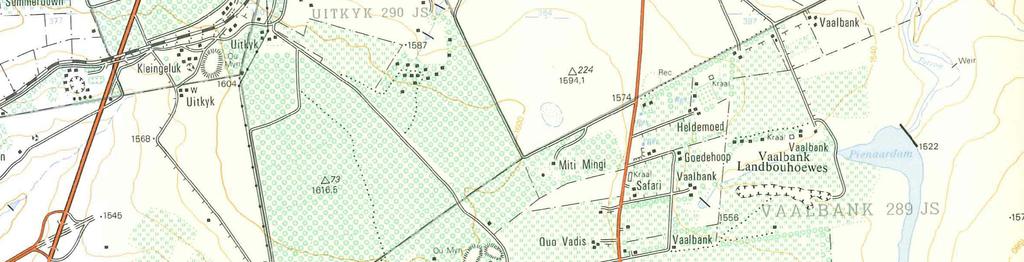
21 Report no 0822/2007 Ref: Samancor 28 August 2007 Mr Dawid Mouton Knight Hall Hendry Tel: Fax: Cel: Dear Dawid REPORT ON RESISTIVITY INVESTIGATION AT SAMANCOR MIDDELBURG 1. Introduction A geophysical investigation comprising the electrical resistivity technique was employed west of the Samancor factory in Middelburg, Mpumalanga. The objective of the investigation was the mapping of the depth of weathering of the underlying sandstone. The layout of the resistivity traverses is presented in Figure Data Acquisition & Processing Resistivity data was acquired with a 48 channel ABEM automatic resistivity system. A total of seven (7) traverses with a total linear distance of approximately 5,560 metres were acquired as shown in Figure 1. Data was processed using RES2DINV to produce modeled resistivity sections. An Omnistar VBS system (sub-metre accuracy) was used to reference the geophysical traverses in WGS-84 LO-29 coordinate system. GLOBAL GEOPHYSICAL PO Box Erasmuskloof 0048 South Africa Tel: Fax: Cellular: alten@globalgeo.co.za Internet:
22 3. Results & Recommendations The resistivity results are presented in section format in Appendix 1 where resistivity is presented as a function of chainage and depth. A depth penetration of approximately 50 metres was achieved. Resistivities of between 10 and 2,000 Ohm.m were observed, with the higher resistivities typical of more competent bedrock, while lower resistivities are typically caused by the presence of weathered material, clay, higher subsurface porosity, presence of groundwater, etc. Different rock types may also have different resistivity, for example shale is generally less resistive than sandstone. Unweathered dolerite typically has very high resistivity compared to typical Karoo sediments, and sills and dykes will thus usually appear as very resistive features. A total of eight (8) depth sections were extracted from the resistivity data at the following depths: Table 1. Resistivity Depth Slices Figure # Depth depth Figure Figure Figure Figure Figure Figure Figure Figure These depth slices provide an alternative view of subsurface resistivities as it represent the spatial change in resistivity at a specific depth. The following conclusions can be made from the section and depth slice information: A prominent increase in resistivity from west to east can be observed at a specific depth for most of the depth slices. This confirms the presence of a highly resistive zone becomes shallower towards the eastern part of the site. This may also be interpreted as a decrease in the depth of weathering towards the eastern part of the site, or the presence of a more resistive rock type such as dolerite towards the eastern part of the site. A zone of very high resistivities can be observed from E+200 to E+500 which can be clearly observed on Line E (Appendix 1) and also in Figures 3 6. The high resistivities observed and the rapid lateral changes in resistivity suggest the presence of an intrusive feature such as a dolerite sill. The depth of weathering is thus interpreted to be very shallow in this area, and a confirmation borehole is recommended in this area to confirm the presence of dolerite and the depth of weathering. GLOBAL GEOPHYSICAL PO Box Erasmuskloof 0048 South Africa Tel: Fax: Cellular: alten@globalgeo.co.za Internet:
23 A zone of very low resistivities can be observed on E+00 to E+300 and also on F+00 to F+100. This occurs in a zone where high resistivities occur at depths greater than 35 metres which is interpreted as possible dolerite. The low resistivities may thus represent shallow clay in this area. It is recommended that a number of boreholes be drilled in the zones of different resistivities to finalize the interpretation of the geophysical results. Yours sincerely Alten du Plessis (Pr.Sci.Nat) trading as GLOBAL GEOPHYSICAL GLOBAL GEOPHYSICAL PO Box Erasmuskloof 0048 South Africa Tel: Fax: Cellular: alten@globalgeo.co.za Internet:
24 FIGURE 1. SAMANCOR MIDDELBURG RESISTIVITY LOCALITY MAP Old Runway B+00 C+00 road A+00 B+100 fence C+100 A+100 B D+0 C+200 E+0 A+200 B D+100 C+300 E+100 A+300 B A+400 A+500 BH/N3/880 D+200 road B+500 borehole/fence D+300 B+600 C+400 E+200 C+500 E+300 F+100 F+200 F power line A+600 F+470 F+400 B+700 F+300 D+400 C+600 E A+700 B+800 D+500 C+700 E+500 road Boreholes Resistivity Lines A+800 A+900 G+470 B+900 B+1000 G+400 D+600 G+300 B+1050 C+800 G+200 D+700 D+710 C+900 G+100 C+950 E+600 G+0 E+700 E A+1000 A+1100 Coordinate System Project 0822/2007 WGS-84 LO August 2007 A
25 FIGURE 2. SAMANCOR MIDDELBURG RESISTIVITY DEPTH SECTION 2.5 METRES B+00 C A+00 B+100 C+100 A+100 B D+0 C+200 E+0 A+200 B D+100 C+300 E+100 A+300 B A+400 A+500 D+200 B+500 D+300 B+600 C+400 E+200 C+500 E+300 F+100 F+200 F A+600 F+470 F+400 B+700 F+300 D+400 C+600 E A+700 B+800 D+500 C+700 E A+800 A+900 G+470 B+900 B+1000 G+400 D+600 G+300 B+1050 C+800 G+200 D+700 D+710 C+900 G+100 C+950 E+600 G+0 E+700 E A+1000 A+1100 Coordinate System Project 0822/2007 WGS-84 LO August 2007 A
26 FIGURE 3. SAMANCOR MIDDELBURG RESISTIVITY DEPTH SECTION 7.5 METRES B+00 C A+00 B+100 C+100 A+100 B D+0 C+200 E+0 A+200 B D+100 C+300 E+100 A+300 B A+400 A+500 D+200 B+500 D+300 B+600 C+400 E+200 C+500 E+300 F+100 F+200 F A+600 F+470 F+400 B+700 F+300 D+400 C+600 E A+700 B+800 D+500 C+700 E A+800 A+900 G+470 B+900 B+1000 G+400 D+600 G+300 B+1050 C+800 G+200 D+700 D+710 C+900 G+100 C+950 E+600 G+0 E+700 E A+1000 A+1100 Coordinate System Project 0822/2007 WGS-84 LO August 2007 A
27 FIGURE 4. SAMANCOR MIDDELBURG RESISTIVITY DEPTH SECTION METRES B+00 C A+00 B+100 C+100 A+100 B D+0 C+200 E+0 A+200 B D+100 C+300 E+100 A+300 B A+400 A+500 D+200 B+500 D+300 B+600 C+400 E+200 C+500 E+300 F+100 F+200 F A+600 F+470 F+400 B+700 F+300 D+400 C+600 E A+700 B+800 D+500 C+700 E A+800 A+900 G+470 B+900 B+1000 G+400 D+600 G+300 B+1050 C+800 G+200 D+700 D+710 C+900 G+100 C+950 E+600 G+0 E+700 E A+1000 A+1100 Coordinate System Project 0822/2007 WGS-84 LO August 2007 A
28 FIGURE 5. SAMANCOR MIDDELBURG RESISTIVITY DEPTH SECTION METRES B+00 C A+00 B+100 C+100 A+100 B D+0 C+200 E+0 A+200 B D+100 C+300 E+100 A+300 B A+400 A+500 D+200 B+500 D+300 B+600 C+400 E+200 C+500 E+300 F+100 F+200 F A+600 F+470 F+400 B+700 F+300 D+400 C+600 E A+700 B+800 D+500 C+700 E A+800 A+900 G+470 B+900 B+1000 G+400 D+600 G+300 B+1050 C+800 G+200 D+700 D+710 C+900 G+100 C+950 E+600 G+0 E+700 E A+1000 A+1100 Coordinate System Project 0822/2007 WGS-84 LO August 2007 A
29 FIGURE 6. SAMANCOR MIDDELBURG RESISTIVITY DEPTH SECTION 25 METRES B+00 C A+00 B+100 C+100 A+100 B D+0 C+200 E+0 A+200 B D+100 C+300 E+100 A+300 B A+400 A+500 D+200 B+500 D+300 B+600 C+400 E+200 C+500 E+300 F+100 F+200 F A+600 F+470 F+400 B+700 F+300 D+400 C+600 E A+700 B+800 D+500 C+700 E A+800 A+900 G+470 B+900 B+1000 G+400 D+600 G+300 B+1050 C+800 G+200 D+700 D+710 C+900 G+100 C+950 E+600 G+0 E+700 E A+1000 A+1100 Coordinate System Project 0822/2007 WGS-84 LO August 2007 A
30 FIGURE 7. SAMANCOR MIDDELBURG RESISTIVITY DEPTH SECTION 32 METRES B+00 C A+00 B+100 C+100 A+100 B D+0 C+200 E+0 A+200 B D+100 C+300 E+100 A+300 B A+400 A+500 D+200 B+500 D+300 B+600 C+400 E+200 C+500 E+300 F+100 F+200 F A+600 F+470 F+400 B+700 F+300 D+400 C+600 E A+700 B+800 D+500 C+700 E A+800 A+900 G+470 B+900 B+1000 G+400 D+600 G+300 B+1050 C+800 G+200 D+700 D+710 C+900 G+100 C+950 E+600 G+0 E+700 E A+1000 A+1100 Coordinate System Project 0822/2007 WGS-84 LO August 2007 A
31 FIGURE 8. SAMANCOR MIDDELBURG RESISTIVITY DEPTH SECTION 39.5 METRES B+00 C A+00 B+100 C+100 A+100 B D+0 C+200 E+0 A+200 B D+100 C+300 E+100 A+300 B A+400 A+500 D+200 B+500 D+300 B+600 C+400 E+200 C+500 E+300 F+100 F+200 F A+600 F+470 F+400 B+700 F+300 D+400 C+600 E A+700 B+800 D+500 C+700 E A+800 A+900 G+470 B+900 B+1000 G+400 D+600 G+300 B+1050 C+800 G+200 D+700 D+710 C+900 G+100 C+950 E+600 G+0 E+700 E A+1000 A+1100 Coordinate System Project 0822/2007 WGS-84 LO August 2007 A
32 FIGURE 9. SAMANCOR MIDDELBURG RESISTIVITY DEPTH SECTION 48METRES B+00 C A+00 B+100 C+100 A+100 B D+0 C+200 E+0 A+200 B D+100 C+300 E+100 A+300 B A+400 A+500 D+200 B+500 D+300 B+600 C+400 E+200 C+500 E+300 F+100 F+200 F A+600 F+470 F+400 B+700 F+300 D+400 C+600 E A+700 B+800 D+500 C+700 E A+800 A+900 G+470 B+900 B+1000 G+400 D+600 G+300 B+1050 C+800 G+200 D+700 D+710 C+900 G+100 C+950 E+600 G+0 E+700 E A+1000 A+1100 Coordinate System Project 0822/2007 WGS-84 LO August 2007 A
33 Appendix 1 Resistivity Model Sections
34 Line A
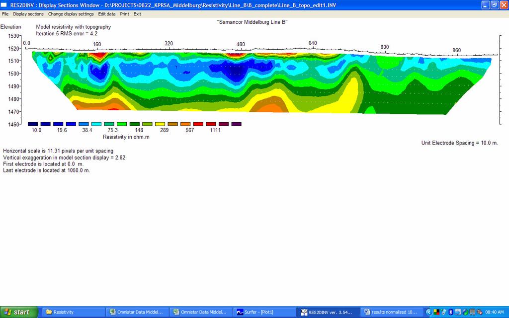
35 Line B
36 Line C
37 Line D
38 Line E
39 Line F
40 Line G
41 Appendix 2 Resistivity Coordinates (WG-29) X Y Z Peg A A A A A A A A A A A A A B B B B B B B B B B B B C C C C C C C C C C C D D D D D D D D D+710
42 E E E E E E E E E F F F F F F G G G G G G+470
43 APPENDIX B TEST PIT PROFILES JDC-JvT/5266 /KHH Rev.0 ( )
44 KNIGHT HALL HENDRY GEOTECHNICAL ENGINEERS TEL: FAX: SAMANCOR FERROCHROME MIDDELBURG GEOTECHNICAL INVESTIGATION HOLE No: TP1 Sheet 1 of 1 JOB NUMBER: 5266 TP1/1 TP1/2 Scale 1: Slightly moist, greyish brown speckled light brown, medium dense, intact, gravelly silty SAND, with pebble marker present at bottom, and roots. HILLWASH. Slightly moist, greyish brown stained orange speckled black and brown, dense to very dense, relict layered, slightly sandy silty GRAVEL. RESIDUAL SHALE. Highly to moderately weathered, light maroonish brown, thinly bedded and very closely to closely jointed, very soft rock SHALE. EOH: Excavator refusal on soft rock SHALE. NOTES 1) No water seepage encountered. 2) Bulk sample TP1/1 taken between 0,3m--0,8m. 3) Rock sample TP1/2 taken between 1,1m--1,3m. D040 CONTRACTOR : Zentex Plant Hire MACHINE : Excavator 33 ton DRILLED BY : PROFILED BY : J van Tonder TYPE SET BY : EM SETUP FILE : KHHTP.SET INCLINATION : Vertical DIAM : DATE : DATE : 1-3 August 2007 DATE : 06/11/07 08:42 TEXT :..\PROFILES\IYW-JVTA.PRO ELEVATION : X-COORD : Y-COORD : HOLE No: TP1 dot.plot 4015 J&W
45 KNIGHT HALL HENDRY GEOTECHNICAL ENGINEERS TEL: FAX: SAMANCOR FERROCHROME MIDDELBURG GEOTECHNICAL INVESTIGATION HOLE No: TP2 Sheet 1 of 1 JOB NUMBER: 5266 Scale 1: Slightly moist, greyish brown speckled black and grey, loose, intact, gravelly silty SAND, with roots. Pebble marker present at bottom. HILLWASH. Moist, light to dark brown stained black, firm, intact, slightly sandy gravelly silty CLAY. RESIDUAL SHALE. Highly weathered, light maroon stained orange and black, closely jointed, very soft rock QUARTZITE band. Note: Quartzite band dipping northwards approximately 20 degrees. Moist, dark brown blotched orange, firm, intact, slightly sandy silty CLAY. RESIDUAL SHALE. Highly to moderately weathered, greyish maroon stained orange and black, closely jointed, soft to medium hard rock QUARTZITE band, dipping 20 degrees northwards. Moist, dark brown blotched orange, firm, intact, slightly sandy silty CLAY. RESIDUAL SHALE. Highly to moderately weathered, greyish maroon stained orange and black, closely jointed, soft to medium hard rock QUARTZITE band, dipping 20 degrees northwards. Highly weathered, light maroon to brown, thinly bedded, very soft rock SHALE. EOH: Excavator stopped on soft to medium hard rock QUARTZITE. NOTES 1) No water seepage encountered. D040 CONTRACTOR : Zentex Plant Hire MACHINE : Excavator 33 ton DRILLED BY : PROFILED BY : J van Tonder TYPE SET BY : EM SETUP FILE : KHHTP.SET INCLINATION : Vertical DIAM : DATE : DATE : 1-3 August 2007 DATE : 06/11/07 08:42 TEXT :..\PROFILES\IYW-JVTA.PRO ELEVATION : X-COORD : Y-COORD : HOLE No: TP2 dot.plot 4015 J&W
46 KNIGHT HALL HENDRY GEOTECHNICAL ENGINEERS TEL: FAX: SAMANCOR FERROCHROME MIDDELBURG GEOTECHNICAL INVESTIGATION HOLE No: TP3 Sheet 1 of 1 JOB NUMBER: 5266 Scale 1: Slightly moist, brown speckled black and grey, medium dense, intact, gravelly clayey silty SAND, with roots. HILLWASH. Note: No defined pebble marker. Slightly moist, brownish orange, stiff, relict thinly bedded, sandy clayey SILT. RESIDUAL SHALE. TP3/1 TP3/2 TP3/ Highly weathered, light maroonish brown, bedded, closely jointed, soft rock QUARTZITE band, dipping north-east at 20 degrees. Moist, brownish orange, firm, relict thinly bedded, slightly sandy clayey SILT. RESIDUAL SHALE Highly weathered, maroon to dark brown, thinly bedded, very closely jointed, very soft rock SHALE. EOH: Excavator stopped on very soft rock SHALE. NOTES 1) No water seepage encountered. 2) Undisturbed sample TP3/1 taken between 1,5m--1,7m. 3) Undisturbed sample TP3/2 taken between 3m--3,2m. 4) Bulk sample TP3/3 taken between 2,5m--3,7m. D040 CONTRACTOR : Zentex Plant Hire MACHINE : Excavator 33 ton DRILLED BY : PROFILED BY : J van Tonder TYPE SET BY : EM SETUP FILE : KHHTP.SET INCLINATION : Vertical DIAM : DATE : DATE : 1-3 August 2007 DATE : 06/11/07 08:42 TEXT :..\PROFILES\IYW-JVTA.PRO ELEVATION : X-COORD : Y-COORD : HOLE No: TP3 dot.plot 4015 J&W
47 KNIGHT HALL HENDRY GEOTECHNICAL ENGINEERS TEL: FAX: SAMANCOR FERROCHROME MIDDELBURG GEOTECHNICAL INVESTIGATION HOLE No: TP4 Sheet 1 of 1 JOB NUMBER: 5266 TP4/1 Scale 1: Slightly moist, greyish brown speckled grey, loose, gravelly silty SAND, with roots. HILLWASH. Dry to slightly moist, brownish orange speckled black, very dense, well cemented, ferruginised silty gravelly SAND. PEDOGENIC (HILLWASH) Slightly moist, light maroon to dark brown, very stiff, relict thinly bedded and closely jointed, gravelly silty CLAY. RESIDUAL SHALE. Highly weathered, light maroon to brown, closely jointed, thinly bedded, very soft rock SHALE. EOH: Excavator stopped in soft rock SHALE. NOTES 1) No water seepage encountered. 2) Small bag sample TP4/1 taken between 0,3m--1,1m. D040 CONTRACTOR : Zentex Plant Hire MACHINE : Excavator 33 ton DRILLED BY : PROFILED BY : J van Tonder TYPE SET BY : EM SETUP FILE : KHHTP.SET INCLINATION : Vertical DIAM : DATE : DATE : 1-3 August 2007 DATE : 06/11/07 08:42 TEXT :..\PROFILES\IYW-JVTA.PRO ELEVATION : X-COORD : Y-COORD : HOLE No: TP4 dot.plot 4015 J&W
48 KNIGHT HALL HENDRY GEOTECHNICAL ENGINEERS TEL: FAX: SAMANCOR FERROCHROME MIDDELBURG GEOTECHNICAL INVESTIGATION HOLE No: TP5 Sheet 1 of 1 JOB NUMBER: m Scale 1: Moist, dark brown speckled grey, soft, intact, gravelly (<30%) silty CLAY. TOPSOIL. Moist, orange brown speckled black, dense, intact, abundant FERRICRETE NODULES in a sandy clayey SILT matrix. NODULAR FERRICRETE. As above, FERRICRETE NODULES (30%) in soft silty clay matrix. Ferruginous RESIDUAL SHALE Highly weathered, light maroon to brown, thinly bedded, very soft rock SHALE. EOH: Excavator stopped in soft rock SHALE. NOTES 1) Water seepage encountered from 0,7m. 2) After ten minutes of excavation the test pit is filled ten millimetres with water. 3) Water sample TP5/1 taken. D040 CONTRACTOR : Zentex Plant Hire MACHINE : Excavator 33 ton DRILLED BY : PROFILED BY : J van Tonder TYPE SET BY : EM SETUP FILE : KHHTP.SET INCLINATION : Vertical DIAM : DATE : DATE : 1-3 August 2007 DATE : 06/11/07 08:42 TEXT :..\PROFILES\IYW-JVTA.PRO ELEVATION : X-COORD : Y-COORD : HOLE No: TP5 dot.plot 4015 J&W
49 KNIGHT HALL HENDRY GEOTECHNICAL ENGINEERS TEL: FAX: SAMANCOR FERROCHROME MIDDELBURG GEOTECHNICAL INVESTIGATION HOLE No: TP6 Sheet 1 of 1 JOB NUMBER: 5266 TP6/1 Scale 1: Slightly moist, greyish brown speckled dark brown, loose, intact, gravelly (<20%) silty SAND, with roots. HILLWASH. Slightly moist, greyish brown stained orange speckled black, dense, intact, FERRICRETE NODULES (>50%) in a slightly sandy silty CLAY matrix. NODULAR FERRICRETE. Slightly moist, dark brownish grey stained orange speckled black, very dense, intact to pinhole voided, abundant FERRICRETE NODULES in a silty clayey SAND matrix. HONEYCOMB FERRICRETE. Note: Tending to hardpan ferricrete between 1,3m and 1,7m and between 2,1m and 2,5m. TP6/ Moist, light maroonish light brown, stiff, intact, slightly sandy silty CLAY. RESIDUAL SHALE Highly weathered, light maroon, thinly bedded, closely jointed, very soft rock SHALE. EOH: Excavator stopped in very soft rock SHALE. NOTES 1) No water seepage encountered. 2) Bulk sample TP6/1 taken between 0,8m--2,7m. 3) Undisturbed sample TP6/2 taken between 2,7m--3,3m. D040 CONTRACTOR : Zentex Plant Hire MACHINE : Excavator 33 ton DRILLED BY : PROFILED BY : J van Tonder TYPE SET BY : EM SETUP FILE : KHHTP.SET INCLINATION : Vertical DIAM : DATE : DATE : 1-3 August 2007 DATE : 06/11/07 08:42 TEXT :..\PROFILES\IYW-JVTA.PRO ELEVATION : X-COORD : Y-COORD : HOLE No: TP6 dot.plot 4015 J&W
50 KNIGHT HALL HENDRY GEOTECHNICAL ENGINEERS TEL: FAX: SAMANCOR FERROCHROME MIDDELBURG GEOTECHNICAL INVESTIGATION HOLE No: TP7 Sheet 1 of 1 JOB NUMBER: 5266 Scale 1: Slightly moist, greyish brown speckled dark brown, loose, intact, gravelly (<30%) silty SAND, with roots. HILLWASH. Slightly moist, brown red stained grey and orange speckled black, dense, intact, FERRICRETE NODULES (40%) in a slightly sandy silty CLAY matrix. NODULAR FERRICRETE. Slightly moist, orange brown stained yellow, stiff to very stiff, relict thinly bedded and jointed, slightly gravelly silty CLAY. Slightly ferruginised RESIDUAL SHALE. Highly weathered, maroon to brown, thinly bedded, closely jointed, very soft rock SHALE Highly weathered, greyish brown stained orange, closely jointed, soft rock QUARTZITE. Highly weathered, maroon to brown stained yellow, thinly bedded, closely jointed, very soft to soft rock SHALE EOH: Excavator stopped in soft rock SHALE. NOTES 1) No water seepage encountered. D040 CONTRACTOR : Zentex Plant Hire MACHINE : Excavator 33 ton DRILLED BY : PROFILED BY : J van Tonder TYPE SET BY : EM SETUP FILE : KHHTP.SET INCLINATION : Vertical DIAM : DATE : DATE : 1-3 August 2007 DATE : 06/11/07 08:42 TEXT :..\PROFILES\IYW-JVTA.PRO ELEVATION : X-COORD : Y-COORD : HOLE No: TP7 dot.plot 4015 J&W
51 KNIGHT HALL HENDRY GEOTECHNICAL ENGINEERS TEL: FAX: SAMANCOR FERROCHROME MIDDELBURG GEOTECHNICAL INVESTIGATION HOLE No: TP8 Sheet 1 of 1 JOB NUMBER: m Scale 1: Moist, dark brown to black, soft, intact, slightly sandy silty CLAY. TOPSOIL. Wet, greyish brown stained orange speckled black, soft, intact, FERRICRETE NODULES (30%) in a silty CLAY matrix. NODULAR FERRICRETE Wet, light maroon stained orange, firm, intact, silty CLAY. RESIDUAL SHALE. TP8/ Highly weathered, maroon, thinly bedded, closely jointed, soft rock SHALE EOH: Excavator stopped in soft rock SHALE. NOTES 1) Water seepage encountered from 0,4m. 2) Undisturbed sample TP8/1 taken between 1,8m--2,0m. D040 CONTRACTOR : Zentex Plant Hire MACHINE : Excavator 33 ton DRILLED BY : PROFILED BY : J van Tonder TYPE SET BY : EM SETUP FILE : KHHTP.SET INCLINATION : Vertical DIAM : DATE : DATE : 1-3 August 2007 DATE : 06/11/07 08:42 TEXT :..\PROFILES\IYW-JVTA.PRO ELEVATION : X-COORD : Y-COORD : HOLE No: TP8 dot.plot 4015 J&W
52 KNIGHT HALL HENDRY GEOTECHNICAL ENGINEERS TEL: FAX: SAMANCOR FERROCHROME MIDDELBURG GEOTECHNICAL INVESTIGATION HOLE No: TP9 Sheet 1 of 1 JOB NUMBER: m Scale 1: Moist, dark brown to black, soft, intact, slightly sandy silty CLAY. TOPSOIL. Wet, greyish brown stained orange speckled black, soft, intact, FERRICRETE NODULES (30%) in a silty CLAY matrix. NODULAR FERRICRETE. TP9/1 TP9/ Wet, light maroon stained orange, soft, intact, sandy silty CLAY. RESIDUAL SHALE Highly weathered, maroon, thinly bedded, closely jointed, soft rock SHALE EOH: Excavator stopped in very soft rock SHALE. NOTES 1) Water seepage encountered from 0,4m. 2) Test pit sidewalls collapsed after twenty minutes. 3) Undisturbed sample TP9/1 taken between 1,4m--1,6m. 4) Bulk sample TP9/2 taken between 1,1m--2,0m. D040 CONTRACTOR : Zentex Plant Hire MACHINE : Excavator 33 ton DRILLED BY : PROFILED BY : J van Tonder TYPE SET BY : EM SETUP FILE : KHHTP.SET INCLINATION : Vertical DIAM : DATE : DATE : 1-3 August 2007 DATE : 06/11/07 08:42 TEXT :..\PROFILES\IYW-JVTA.PRO ELEVATION : X-COORD : Y-COORD : HOLE No: TP9 dot.plot 4015 J&W
53 KNIGHT HALL HENDRY GEOTECHNICAL ENGINEERS TEL: FAX: SAMANCOR FERROCHROME MIDDELBURG GEOTECHNICAL INVESTIGATION HOLE No: TP10 Sheet 1 of 1 JOB NUMBER: m Scale 1: Moist, dark brown to black, soft, intact, slightly sandy silty CLAY. TOPSOIL. Wet, greyish brown speckled black, firm to stiff, intact, FERRICRETE NODULES (20%) in a silty CLAY matrix. Ferruginised RESIDUAL SHALE. Highly weathered, maroon brown, thinly bedded, very closely jointed, very soft rock SHALE. EOH: Excavator stopped in soft rock SHALE. NOTES 1) Water seepage encountered at 0,4m 2) Water sample TP10 taken. D040 CONTRACTOR : Zentex Plant Hire MACHINE : Excavator 33 ton DRILLED BY : PROFILED BY : J van Tonder TYPE SET BY : EM SETUP FILE : KHHTP.SET INCLINATION : Vertical DIAM : DATE : DATE : 1-3 August 2007 DATE : 06/11/07 08:42 TEXT :..\PROFILES\IYW-JVTA.PRO ELEVATION : X-COORD : Y-COORD : HOLE No: TP10 dot.plot 4015 J&W
54 KNIGHT HALL HENDRY GEOTECHNICAL ENGINEERS TEL: FAX: SAMANCOR FERROCHROME MIDDELBURG GEOTECHNICAL INVESTIGATION HOLE No: TP11 Sheet 1 of 1 JOB NUMBER: 5266 Scale 1: Slightly moist, greyish brown speckled grey, loose, intact, silty SAND, with scattered GRAVEL and roots.. HILLWASH. Wet, greyish brown stained orange speckled black, dense, intact, FERRICRETE NODULES (30%) in a clayey SAND matrix. NODULAR FERRICRETE. Highly weathered, maroon brown, thinly bedded, very closely jointed, very soft rock SHALE. EOH: Excavator stopped in soft rock SHALE. NOTES 1) No water seepage encountered. D040 CONTRACTOR : Zentex Plant Hire MACHINE : Excavator 33 ton DRILLED BY : PROFILED BY : J van Tonder TYPE SET BY : EM SETUP FILE : KHHTP.SET INCLINATION : Vertical DIAM : DATE : DATE : 1-3 August 2007 DATE : 06/11/07 08:42 TEXT :..\PROFILES\IYW-JVTA.PRO ELEVATION : X-COORD : Y-COORD : HOLE No: TP11 dot.plot 4015 J&W
55 KNIGHT HALL HENDRY GEOTECHNICAL ENGINEERS TEL: FAX: SAMANCOR FERROCHROME MIDDELBURG GEOTECHNICAL INVESTIGATION HOLE No: TP12 Sheet 1 of 1 JOB NUMBER: 5266 Scale 1: Slightly moist, greyish brown speckled dark grey, loose, intact, silty clayey SAND. HILLWASH, with pebble marker present at bottom of layer. Slightly moist, brownish maroon speckled red, firm to stiff with depth, relict thinly bedded, silty CLAY, with highly weathered shale GRAVEL. RESIDUAL SHALE. Highly weathered, maroon brown, thinly bedded, very closely jointed, very soft rock SHALE. EOH: Excavator stopped in soft rock SHALE. NOTES 1) No water seepage encountered. D040 CONTRACTOR : Zentex Plant Hire MACHINE : Excavator 33 ton DRILLED BY : PROFILED BY : J van Tonder TYPE SET BY : EM SETUP FILE : KHHTP.SET INCLINATION : Vertical DIAM : DATE : DATE : 1-3 August 2007 DATE : 06/11/07 08:42 TEXT :..\PROFILES\IYW-JVTA.PRO ELEVATION : X-COORD : Y-COORD : HOLE No: TP12 dot.plot 4015 J&W
56 KNIGHT HALL HENDRY GEOTECHNICAL ENGINEERS TEL: FAX: SAMANCOR FERROCHROME MIDDELBURG GEOTECHNICAL INVESTIGATION HOLE No: TP13 Sheet 1 of 1 JOB NUMBER: 5266 Scale 1: Slightly moist, brownish grey speckled dark grey, loose, intact, silty clayey SAND. HILLWASH, with pebble marker present at bottom of layer. Slightly moist, brownish orange speckled red, firm to stiff, thinly bedded, silty CLAY, with highly weathered shale GRAVEL. Ferruginised RESIDUAL SHALE. Highly weathered, maroon brown, thinly bedded, very closely jointed, very soft rock SHALE. EOH: Excavator stopped in soft rock SHALE. NOTES 1) No water seepage encountered. D040 CONTRACTOR : Zentex Plant Hire MACHINE : Excavator 33 ton DRILLED BY : PROFILED BY : J van Tonder TYPE SET BY : EM SETUP FILE : KHHTP.SET INCLINATION : Vertical DIAM : DATE : DATE : 1-3 August 2007 DATE : 06/11/07 08:42 TEXT :..\PROFILES\IYW-JVTA.PRO ELEVATION : X-COORD : Y-COORD : HOLE No: TP13 dot.plot 4015 J&W
57 KNIGHT HALL HENDRY GEOTECHNICAL ENGINEERS TEL: FAX: SAMANCOR FERROCHROME MIDDELBURG GEOTECHNICAL INVESTIGATION HOLE No: TP14 Sheet 1 of 1 JOB NUMBER: 5266 Scale 1: Slightly moist, greyish brown speckled grey, loose, intact, silty SAND, with scattered GRAVEL and roots.. HILLWASH. Wet, greyish brown stained orange speckled black, soft, intact, FERRICRETE NODULES (30%) in a silty CLAY matrix. NODULAR FERRICRETE Moist, brownish maroon stained orange, firm becoming gradually firm to stiff with depth, intact to relict thinly bedded, silty CLAY, with completely weathered shale GRAVEL. RESIDUAL SHALE. TP14/1 TP14/ Moist, brownish maroon stained orange, stiff, relict thinly bedded, silty CLAY, with completely weathered shale GRAVEL. RESIDUAL SHALE EOH: Maximum reach of excavator in stiff residual SHALE. NOTES 1) No water seepage encountered. 2) Bulk sample TP14/1 taken between 1,4m--3,4m. 3) Undisturbed block sample TP14/2 taken between 3,2m--3,4m. D040 CONTRACTOR : Zentex Plant Hire MACHINE : Excavator 33 ton DRILLED BY : PROFILED BY : J van Tonder TYPE SET BY : EM SETUP FILE : KHHTP.SET INCLINATION : Vertical DIAM : DATE : DATE : 1-3 August 2007 DATE : 06/11/07 08:42 TEXT :..\PROFILES\IYW-JVTA.PRO ELEVATION : X-COORD : Y-COORD : HOLE No: TP14 dot.plot 4015 J&W
58 KNIGHT HALL HENDRY GEOTECHNICAL ENGINEERS TEL: FAX: SAMANCOR FERROCHROME MIDDELBURG GEOTECHNICAL INVESTIGATION HOLE No: TP15 Sheet 1 of 1 JOB NUMBER: 5266 Scale 1: Slightly moist, greyish brown, soft, intact, sandy silty CLAY. TOPSOIL. Moist, brownish orange stained grey, soft, intact to relict thinly bedded, silty CLAY, with scattered, highly weathered shale GRAVEL. RESIDUAL SHALE. TP15/ Highly weathered, maroon brown, thinly bedded, very closely jointed, very soft rock SHALE EOH: Excavator stopped in soft rock SHALE. NOTES 1) No water seepage encountered. 2) Bulk sample TP15/1 taken between 0,2m--1,4m. D040 CONTRACTOR : Zentex Plant Hire MACHINE : Excavator 33 ton DRILLED BY : PROFILED BY : J van Tonder TYPE SET BY : EM SETUP FILE : KHHTP.SET INCLINATION : Vertical DIAM : DATE : DATE : 1-3 August 2007 DATE : 06/11/07 08:42 TEXT :..\PROFILES\IYW-JVTA.PRO ELEVATION : X-COORD : Y-COORD : HOLE No: TP15 dot.plot 4015 J&W
59 KNIGHT HALL HENDRY GEOTECHNICAL ENGINEERS TEL: FAX: SAMANCOR FERROCHROME MIDDELBURG GEOTECHNICAL INVESTIGATION HOLE No: TP16 Sheet 1 of 1 JOB NUMBER: 5266 Scale 1: Slightly moist, greyish brown speckled grey, soft, intact, sandy silty CLAY, with scattered GRAVEL. TOPSOIL. Wet, greyish brown speckled black, firm, intact, FERRICRETE NODULES (20%) in a silty CLAY matrix. Ferruginised RESIDUAL SHALE Moist, brownish orange, firm, intact, silty CLAY. RESIDUAL SHALE Very moist, brownish orange banded grey, firm, with zones of stiff ( dense) relict layered, slightly sandy silty CLAY to silty SAND. Alternating bands of RESIDUAL SHALE and RESIDUAL QUARTZITE. 4.1m 3.60 Highly weathered, maroon brown, thinly bedded, very closely jointed, very soft rock SHALE EOH: Maximum reach of excavator in very soft rock SHALE. NOTES 1) Water seepage encountered from 4,1m. D040 CONTRACTOR : Zentex Plant Hire MACHINE : Excavator 33 ton DRILLED BY : PROFILED BY : J van Tonder TYPE SET BY : EM SETUP FILE : KHHTP.SET INCLINATION : Vertical DIAM : DATE : DATE : 1-3 August 2007 DATE : 06/11/07 08:42 TEXT :..\PROFILES\IYW-JVTA.PRO ELEVATION : X-COORD : Y-COORD : HOLE No: TP16 dot.plot 4015 J&W
60 KNIGHT HALL HENDRY GEOTECHNICAL ENGINEERS TEL: FAX: SAMANCOR FERROCHROME MIDDELBURG GEOTECHNICAL INVESTIGATION HOLE No: TP17 Sheet 1 of 1 JOB NUMBER: m Scale 1: Slightly moist, greyish brown, soft, intact, sandy silty CLAY. TOPSOIL. Wet, orange brown stained black and red, soft, intact, silty CLAY. RESIDUAL SHALE. Ferruginised in upper 200mm of layer Completely weathered, maroon brown, thinly bedded, very closely jointed, very soft rock SHALE, with zones of completely weathered shale (clay) present. Tending to very stiff residual shale Highly weathered, maroon, thinly bedded, very soft rock SHALE EOH: Excavator stopped in very soft rock SHALE. NOTES 1) Water seepage encountered from surface and from 0,7m. 2) Test pit collapsed after twenty minutes of exposure. D040 CONTRACTOR : Zentex Plant Hire MACHINE : Excavator 33 ton DRILLED BY : PROFILED BY : J van Tonder TYPE SET BY : EM SETUP FILE : KHHTP.SET INCLINATION : Vertical DIAM : DATE : DATE : 1-3 August 2007 DATE : 06/11/07 08:42 TEXT :..\PROFILES\IYW-JVTA.PRO ELEVATION : X-COORD : Y-COORD : HOLE No: TP17 dot.plot 4015 J&W
61 KNIGHT HALL HENDRY GEOTECHNICAL ENGINEERS TEL: FAX: SAMANCOR FERROCHROME MIDDELBURG GEOTECHNICAL INVESTIGATION HOLE No: TP18 Sheet 1 of 1 JOB NUMBER: 5266 Scale 1: Slightly moist, brown speckled red, firm, intact, slightly sandy clayey SILT, with scattered ferricrete nodules. Ferruginised. HILLWASH Slightly moist, brownish orange to grey, firm, intact to thinly bedded, slightly sandy silty CLAY. RESIDUAL SHALE Very most, brownish grey, loose to medium dense, intact, clayey silty SAND. RESIDUAL QUARTZITE. 5.4m Completely to highly weathered, light maroon to dark brown, very soft rock QUARTZITE. EOH: Maximum reach of excavator. NOTES 1) Water seepage encountered from 5,4m. D040 CONTRACTOR : Zentex Plant Hire MACHINE : Excavator 33 ton DRILLED BY : PROFILED BY : J van Tonder TYPE SET BY : EM SETUP FILE : KHHTP.SET INCLINATION : Vertical DIAM : DATE : DATE : 1-3 August 2007 DATE : 06/11/07 08:42 TEXT :..\PROFILES\IYW-JVTA.PRO ELEVATION : X-COORD : Y-COORD : HOLE No: TP18 dot.plot 4015 J&W
62 KNIGHT HALL HENDRY GEOTECHNICAL ENGINEERS TEL: FAX: SAMANCOR FERROCHROME MIDDELBURG GEOTECHNICAL INVESTIGATION HOLE No: TP19 Sheet 1 of 1 JOB NUMBER: 5266 Scale 1: Slightly moist, brown speckled grey, loose, intact, clayey silty SAND, with scattered GRAVEL. HILLWASH. Completely to highly weathered, maroon, thinly bedded, very soft rock SHALE Moist, greyish brown stained orange, firm, relict thinly bedded, slightly sandy CLAY. RESIDUAL SHALE Highly to moderately weathered, light maroon to grey, very soft rock SHALE. EOH: Excavator stopped in soft rock SHALE. NOTES 1) No water seepage encountered. D040 CONTRACTOR : Zentex Plant Hire MACHINE : Excavator 33 ton DRILLED BY : PROFILED BY : J van Tonder TYPE SET BY : EM SETUP FILE : KHHTP.SET INCLINATION : Vertical DIAM : DATE : DATE : 1-3 August 2007 DATE : 06/11/07 08:42 TEXT :..\PROFILES\IYW-JVTA.PRO ELEVATION : X-COORD : Y-COORD : HOLE No: TP19 dot.plot 4015 J&W
63 KNIGHT HALL HENDRY GEOTECHNICAL ENGINEERS TEL: FAX: SAMANCOR FERROCHROME MIDDELBURG GEOTECHNICAL INVESTIGATION HOLE No: TP20 Sheet 1 of 1 JOB NUMBER: 5266 Scale 1: Moist, greyish brown speckled grey and dark brown, medium dense, intact, clayey silty SAND, with GRAVEL (35%). Ferruginised HILLWASH Slightly moist, orange to brown speckled light orange, firm, intact, gravelly (30%) silty CLAY. HILLWASH. TP20/ Wet, greyish brown speckled black, firm, intact, slightly sandy CLAY. Ferruginous RESIDUAL SHALE Moist, brownish maroon, firm to stiff below 4,6m, thinly bedded, silty CLAY, with scattered, highly weathered shale GRAVEL. RESIDUAL SHALE. TP20/ EOH: Maximum reach of excavator. NOTES 1) No water seepage encountered. 2) Undisturbed block sample TP20/1 taken between 2,0m--2,2m. 3) Undisturbed block sample TP20/2 taken between 3,8m--4,0m. D040 CONTRACTOR : Zentex Plant Hire MACHINE : Excavator 33 ton DRILLED BY : PROFILED BY : J van Tonder TYPE SET BY : EM SETUP FILE : KHHTP.SET INCLINATION : Vertical DIAM : DATE : DATE : 1-3 August 2007 DATE : 06/11/07 08:42 TEXT :..\PROFILES\IYW-JVTA.PRO ELEVATION : X-COORD : Y-COORD : HOLE No: TP20 dot.plot 4015 J&W
64 KNIGHT HALL HENDRY GEOTECHNICAL ENGINEERS TEL: FAX: SAMANCOR FERROCHROME MIDDELBURG GEOTECHNICAL INVESTIGATION HOLE No: TP21 Sheet 1 of 1 JOB NUMBER: 5266 Scale 1: Moist, greyish brown speckled grey and dark brown, medium dense, intact, clayey silty SAND, with GRAVEL (35%). Ferruginised HILLWASH Slightly moist, brownish grey speckled black, soft, pinholed, slightly sandy silty CLAY, with scattered GRAVEL. HILLWASH, with pebble marker present at bottom of layer. Moist, brownish orange, firm, pinholed, silty CLAY. RESIDUAL SHALE Moist, brownish orange, firm to stiff, thinly bedded silty CLAY. RESIDUAL SHALE EOH: Excavator stopped in stiff residual SHALE. NOTES 1) No water seepage encountered. D040 CONTRACTOR : Zentex Plant Hire MACHINE : Excavator 33 ton DRILLED BY : PROFILED BY : J van Tonder TYPE SET BY : EM SETUP FILE : KHHTP.SET INCLINATION : Vertical DIAM : DATE : DATE : 1-3 August 2007 DATE : 06/11/07 08:42 TEXT :..\PROFILES\IYW-JVTA.PRO ELEVATION : X-COORD : Y-COORD : HOLE No: TP21 dot.plot 4015 J&W
65 KNIGHT HALL HENDRY GEOTECHNICAL ENGINEERS TEL: FAX: SAMANCOR FERROCHROME MIDDELBURG GEOTECHNICAL INVESTIGATION HOLE No: TP22 Sheet 1 of 1 JOB NUMBER: 5266 Scale 1: Slightly moist, brownish grey speckled dark grey, loose, intact, silty clayey SAND. HILLWASH, with pebble marker present at bottom of layer Slightly moist, brownish orange, firm, intact, silty CLAY. RESIDUAL SHALE Slightly moist, brownish orange to light maroon, firm to stiff becoming stiff below 4,0m, relict thinly bedded, silty CLAY, with highly weathered shale GRAVEL. RESIDUAL SHALE Highly weathered, maroon brown, thinly bedded, very closely jointed, very soft rock SHALE. EOH: Excavator stopped in very soft rock SHALE. NOTES 1) No water seepage encountered. D040 CONTRACTOR : Zentex Plant Hire MACHINE : Excavator 33 ton DRILLED BY : PROFILED BY : J van Tonder TYPE SET BY : EM SETUP FILE : KHHTP.SET INCLINATION : Vertical DIAM : DATE : DATE : 1-3 August 2007 DATE : 06/11/07 08:42 TEXT :..\PROFILES\IYW-JVTA.PRO ELEVATION : X-COORD : Y-COORD : HOLE No: TP22 dot.plot 4015 J&W
66 APPENDIX C LABORATORY TEST RESULTS OF SOIL SAMPLES JDC-JvT/5266 /KHH Rev.0 ( )
67 PARTICLE SIZE ANALYSIS Sample No Soillab sample no. S A-01 S A-02 PROJECT : SAMANCOR CR MIDDELBURG Depth (m) JOB No. : S A Position TP 1 TP 3 DATE : Material DARK BROWN DUSKY RED Description SHALE Moisture (%) SG SANDY GRAVEL SCREEN ANALYSIS ( % PASSING) SILTY SAND 63.0 mm mm mm mm mm mm mm mm mm mm HYDROMETER ANALYSIS ( % PASSING) PI of whole sample POTENTIAL EXPANSIVENESS M E D I U M H I G H Clay fraction of whole sample VERY HIGH LOW mm mm mm mm mm 7 25 % Clay 7 25 % Silt % Sand % Gravel 56 1 ATTERBERG LIMITS Liquid Limit Plasticity Index Linear Shrinkage (%) Grading Modulus Classification A-2-6 (1) A-6 (10) Unified Classification SC CL Chart Reference 0 Plasticity Index PLASTICITY CHART Liquit Limit Cumulative % passing CLAY SILT SAND GRAVEL HIDROMETER/0840A-01
68 PARTICLE SIZE ANALYSIS Sample No Soillab sample no. S A-03 S A-04 PROJECT : SAMANCOR CR MIDDELBURG Depth (m) JOB No. : S A Position TP 3 TP 3 DATE : Material DARK BROWN PALE RED Description Moisture (%) SG SANDY SILT SCREEN ANALYSIS ( % PASSING) SANDY SILT 63.0 mm mm mm mm mm mm mm mm mm mm HYDROMETER ANALYSIS ( % PASSING) PI of whole sample POTENTIAL EXPANSIVENESS M E D I U M H I G H Clay fraction of whole sample VERY HIGH LOW mm mm mm mm mm % Clay % Silt % Sand % Gravel 0 3 ATTERBERG LIMITS Liquid Limit Plasticity Index Linear Shrinkage (%) Grading Modulus Classification A-6 (10) A-6 (9) Unified Classification CL CL Chart Reference 0 Plasticity Index PLASTICITY CHART Liquit Limit Cumulative % passing CLAY SILT SAND GRAVEL HIDROMETER/0840A-02
69 PARTICLE SIZE ANALYSIS Sample No Soillab sample no. S A-05 S A-07 PROJECT : SAMANCOR CR MIDDELBURG Depth (m) JOB No. : S A Position TP 4 TP 6 DATE : Material DARK BROWN LIGHT BROWN Description FERRICRETE FERRICRETE Moisture (%) SG GRAVELLY SAND SCREEN ANALYSIS ( % PASSING) SANDY GRAVEL 63.0 mm mm mm mm mm mm mm mm mm mm HYDROMETER ANALYSIS ( % PASSING) PI of whole sample POTENTIAL EXPANSIVENESS M E D I U M H I G H Clay fraction of whole sample VERY HIGH LOW mm mm mm mm mm 7 12 % Clay 7 12 % Silt % Sand % Gravel ATTERBERG LIMITS Liquid Limit Plasticity Index Linear Shrinkage (%) Grading Modulus Classification A-2-6 (0) A-2-7 (2) Unified Classification SC SC Chart Reference 0 Plasticity Index PLASTICITY CHART Liquit Limit Cumulative % passing CLAY SILT SAND GRAVEL HIDROMETER/0840A-03
70 PARTICLE SIZE ANALYSIS Sample No Soillab sample no. S A-08 S A-09 PROJECT : SAMANCOR CR MIDDELBURG Depth (m) JOB No. : S A Position TP 6 TP 8 DATE : Material LIGHT BROWN LIGHT BROWN Description FDERROCIOUS FERRICRETE Moisture (%) SG SILTY CLAY SCREEN ANALYSIS ( % PASSING) SILTY CLAY 63.0 mm mm mm mm mm mm mm mm mm mm HYDROMETER ANALYSIS ( % PASSING) PI of whole sample POTENTIAL EXPANSIVENESS M E D I U M H I G H Clay fraction of whole sample VERY HIGH LOW mm mm mm mm mm % Clay % Silt % Sand % Gravel 6 7 ATTERBERG LIMITS Liquid Limit Plasticity Index Linear Shrinkage (%) Grading Modulus Classification A-7-5 (15) A-7-6 (16) Unified Classification MH CH Chart Reference 0 Plasticity Index PLASTICITY CHART Liquit Limit Cumulative % passing CLAY SILT SAND GRAVEL HIDROMETER/0840A-04
71 PARTICLE SIZE ANALYSIS Sample No Soillab sample no. S A-10 S A-11 PROJECT : SAMANCOR CR MIDDELBURG Depth (m) JOB No. : S A Position TP 9 TP 9 DATE : Material DARK BROWN LIGHT BROWN Description FERRICRETE Moisture (%) SG SILTY CLAY SCREEN ANALYSIS ( % PASSING) SANDY CLAY 63.0 mm mm mm mm mm mm mm mm mm mm HYDROMETER ANALYSIS ( % PASSING) PI of whole sample POTENTIAL EXPANSIVENESS M E D I U M H I G H Clay fraction of whole sample VERY HIGH LOW mm mm mm mm mm % Clay % Silt % Sand % Gravel 4 6 ATTERBERG LIMITS Liquid Limit Plasticity Index Linear Shrinkage (%) Grading Modulus Classification A-7-6 (17) A-7-6 (18) Unified Classification CH CH Chart Reference 0 Plasticity Index PLASTICITY CHART Liquit Limit Cumulative % passing CLAY SILT SAND GRAVEL HIDROMETER/0840A-05
72 PARTICLE SIZE ANALYSIS Sample No Soillab sample no. S A-13 PROJECT : SAMANCOR CR MIDDELBURG Depth (m) JOB No. : S A Position TP 15 DATE : Material DARK YELLOW Description Moisture (%) SG CLAYEY SILT SCREEN ANALYSIS ( % PASSING) 63.0 mm mm mm mm mm mm mm mm mm mm 85 HYDROMETER ANALYSIS ( % PASSING) PI of whole sample POTENTIAL EXPANSIVENESS M E D I U M H I G H Clay fraction of whole sample VERY HIGH LOW mm mm mm mm mm 34 % Clay 34 % Silt 40 % Sand 24 % Gravel 1 ATTERBERG LIMITS Liquid Limit 42 Plasticity Index 19 Linear Shrinkage (%) 8.5 Grading Modulus 0.21 Classification A-7-6 (12) Unified Classification CH Chart Reference 0 Plasticity Index PLASTICITY CHART Liquit Limit Cumulative % passing CLAY SILT SAND GRAVEL HIDROMETER/0840A-06
73 SOIL ANALYSIS BY...: SOILLAB (Pty) Ltd Lab reference No. : S A Customer... : KNIGHT HALL & HENDRY Job Description... : SAMACOR CR MIDDELBURG Road Number...: Page : 1 Date Printed : Job Number... : S A Contract Number...: Date... : SAMPLE DESCRIPTION Sample Number Sample Position... TP1 TP3 TP6 TP9 TP15 Sample Depth (mm) Material Description... DARK BROWN PALE RED SHALE LIGHT BROWN LIGHT BROWN DARK YELLOW SHALE CLAY FERRICRETE FERRICRETE W/GRANITE CLAYEY GRAVEL CLAYEY GRAVEL CLAY CLAY Max size of boulder (mm) SCREEN ANALYSIS (% PASS) 75,00 mm ,00 mm ,00 mm ,50 mm ,50 mm ,00 mm ,20 mm ,750 mm ,000 mm ,425 mm ,075 mm SOIL MORTAR Coarse Sand 2,000-0, Coarse Fine Sd 0,425-0, Medium Fine Sd 0,250-0, Fine Fine Sand 0,150-0, Material CONSTANTS <0, Grading Modulus Liquid Limit Plasticity Index Linear Shrinkage (%) Sand Equivalent... Classification - TRB... A-2-6 (1) A-6 (9) A-2-7 (2) A-7-6 (18) A-7-6 (12) Classification - COLTO... >G9 >G9 >G9 >G9 >G9 CBR / UCS VALUES MOD. AASHTO Max Dry Density (kg/m³)... CBR 1976 CBR 1787 CBR 2076 CBR 1861 CBR 1827 Optimum Moisture Cont (%) Moulding Moisture Cont (%) Dry Density (kg/m³) % of Max Dry Density % Mod CBR/UCS % Swell NRB Dry Density (kg/m³) % of Max Dry Density % NRB CBR/UCS % Swell PROCTOR Dry Density (kg/m³) % of Max Dry Density % Proc CBR/UCS % Swell CBR / UCS VALUES 100% Mod AASHTO % Mod AASHTO % Mod AASHTO % Mod AASHTO % Mod AASHTO % Mod AASHTO Soillab No... S A-01 S A-04 S A-07 S A-11 S A-13
74 CLIENT : KNIGHT HALL HENDRY & ASSOCIATES PROJECT : SAMANCOR CR MIDDELBURG PROJECT NO. : S A DATE : PERMEABILITY ON REMOULDED SAMPLES Max. Mod Depth Optimum Head of Coëfficiënt of AASTHO Soillab Sample Moisture Water Permeability Dry Density No No Content (m) (kg/m 3 ) (%) (cm) (cm/s) S A-04 TP x 10-8 S A-07 TP Falling Head x 10-8 S A-11 TP Falling Head x 10-8 S A-13 TP Falling Head x 10-8 Note: Remoulded to 95% Max. Mod AASHTO Dry Optimum Moisture PERMEABILITY ON UNDISTURBED SAMPLES Depth Insitu Insitu Head of Coëfficiënt of Soillab No Sample No Dry Density Moisture Content Water Permeability (m) (kg/m 3 ) (%) (cm) (cm/s) S A-02 TP Falling Head 8.47 x 10⁻⁸ S A-03 TP x 10-6 S A-08 TP Falling Head x 10-8 S A-09 TP Falling Head x 10-9 S A-10 TP Falling Head x A-01 1
75 DRAINED DIRECT SHEAR TEST PROJECT SAMANCOR CR MIDDELBURG SAMPLE NO. TP 3 SAMPLE DEPTH (m) NORMAL STRESS STRESS (kn/m²) PEAK SHEAR DISPLACEMENT (mm) PEAK ANGLE OF INTERNAL FRICTION (DEG) COHESION (kn/m²) INITIAL MOISTURE MOISTURE AFTER TEST INITIAL DRY DENSITY (kn/m²) (%) (%) (kg/m³) SHEAR STRESS (kn/m²) NORMAL STRESS (kn/m²) STRESS (kn/m²) STRAIN NOTE(1): NOTE(2): THE ABOVE UNDISTURBED SOIL SAMPLE WERE TESTED IN A SATURATED CONDITION UNDER SELECTED NORMAL LOADS IN A 50.0 mm DIAMETER BOX USING A CONTROLLED RATE OF DISPLACEMENT OF mm PER MINUTE. SOILLAB SAMPLE No.: S A-03 BOXSHR/0840A-03
76 DRAINED DIRECT SHEAR TEST PROJECT SAMANCOR CR MIDDELBURG SAMPLE NO. TP 3/3 SAMPLE DEPTH (m) NORMAL STRESS STRESS (kn/m²) PEAK SHEAR DISPLACEMENT (mm) PEAK ANGLE OF INTERNAL FRICTION (DEG) COHESION (kn/m²) OPTIMUM MOISTURE MOISTURE AFTER TEST GIVEN DRY DENSITY (kg/m³) (kn/m²) (%) (%) SHEAR STRESS (kn/m²) NORMAL STRESS (kn/m²) STRESS (kn/m²) STRAIN NOTE(1): NOTE(2): NOTE(3): THE ABOVE REMOULDED SOIL SAMPLE WERE TESTED IN A SATURATED CONDITION UNDER SELECTED NORMAL LOADS IN A 50.0 mm DIAMETER BOX USING A CONTROLLED RATE OF DISPLACEMENT OF mm PER MINUTE. THE ABOVE SAMPLES WERE COMPACTED TO 95% OF GIVEN MAXIMUM DRY OPTIMUM MOISTURE CONTENT. SOILLAB SAMPLE No.: S A-04 BOXSHR/0840A-04
 Durability Durability Durability Durability Note No No.")
77 TABLE 3 RESULTS OF SLAKE-DURABILITY INDEX TESTS Client: SPECIMEN PARTICULARS Sampling Location: SLAKE-DURABILITY INDEX TEST RESULTS 17-Sep-07 Rocklab Block Rock Tray Mass Mass after cycles Slake Slake Slake Slake Durability Specimen or Drum including (including tray mass) Durability Durability Durability Durability Note No No. Type Mass Tray Index Index Index Index D A Cd1 Cd2 Cd3 Cd4 (1st Cycle) (2nd Cycle) (3rd Cycle) (4thCycle) Class g g g g g g Id1 Id2 Id3 Id4 SDI a Medium Note: All tests were conducted according to the ISRM's specification. Durability is classified according to its slake-durability index at 2nd cycle using the classification table recommended by ISRM and proposed by Gamble (1971)
REPORT NO 12/115/D NOVEMBER 2012 GEOTECHNICAL INVESTIGATION FOR THE PROPOSED SOLAR PHOTOVOLTAIC FACILITY, GROOTVLEI POWER STATION
 Consulting Geotechnical Engineers & Engineering Geologists P.O.Box 3557 Cramerview 2060. Tel: (011) 465-1699. Fax: (011) 465-4586. Cell 082 556 7302 & 076 966 8445 REPORT NO 12/115/D NOVEMBER 2012 GEOTECHNICAL
Report to Tyris Realty on a Geotechnical Investigation for a Proposed Warehouse Development at Sprite Place, Westmead
 Report to Tyris Realty on a Geotechnical Investigation for a Proposed Warehouse Development at Sprite Place, Westmead Reference : 11-358 Dated : February 2012 MOORE SPENCE JONES (PTY) LTD Consulting Geotechnical,
GEOTECHNICAL PHASE 1
 GEOTECHNICAL PHASE 1 FOR PROPOSED SKUKUZA SAFARI LODGE FOR KRUGER NATIONAL PARK MPUMALANGA PROVINCE SEPTEMBER 2014 Report No: G14-0902 Issue 2 Prepared by: Conic North Consulting Engineers PO Box 11862
 Project: ITHACA-TOMPKINS REGIONAL AIRPORT EXPANSION Project Location: ITHACA, NY Project Number: 218-34 Key to Soil Symbols and Terms TERMS DESCRIBING CONSISTENCY OR CONDITION COARSE-GRAINED SOILS (major
REPORT TO TGC ENGINEERS CC. ON A GEOTECHNICAL INVESTIGATION FOR A PROPOSED NEW LANDFILL, CANDIDATE SITE 1 KRANTZ FONTEIN FARM KOKSTAD
 REPORT TO TGC ENGINEERS CC. ON A GEOTECHNICAL INVESTIGATION FOR A PROPOSED NEW LANDFILL, CANDIDATE SITE 1 KRANTZ FONTEIN FARM KOKSTAD 1. INTRODUCTION Drennan, Maud and Partners was requested by Mr Graham
Lima Project: Seismic Refraction and Resistivity Survey. Alten du Plessis Global Geophysical
 Lima Project: Seismic Refraction and Resistivity Survey Alten du Plessis Global Geophysical Report no 0706/2006 18 December 2006 Lima Project: Seismic Refraction and Resistivity Survey by Alten du Plessis
16 January 2018 Job Number: RICHARD NEWMAN C\- CLARK FORTUNE MCDONALD AND ASSOCIATES PO BOX 553 QUEENSTOWN
 16 January 2018 Job Number: 50595 RICHARD NEWMAN C\- CLARK FORTUNE MCDONALD AND ASSOCIATES PO BOX 553 QUEENSTOWN CHANSEN@CFMA.CO.NZ STORMWATER DISPOSAL ASSESSMENT Dear Richard, RDAgritech were requested
Geology and Soil Mechanics /1A ( ) Mark the best answer on the multiple choice answer sheet.
 Mark the best answer on the multiple choice answer sheet.") Geology and Soil Mechanics 55401 /1A (2003-2004) Mark the best answer on the multiple choice answer sheet. 1. Soil mechanics is the application of hydraulics, geology and mechanics to problems relating
Geology and Soil Mechanics 55401 /1A (2003-2004) Mark the best answer on the multiple choice answer sheet. 1. Soil mechanics is the application of hydraulics, geology and mechanics to problems relating
GEOTECHNICAL INVESTIGATION FOR REDHOUSE CHELSEA ARTERIAL AND WALKER DRIVE EXTENSION, PORT ELIZABETH, EASTERN CAPE
 GEOTECHNICAL INVESTIGATION FOR REDHOUSE CHELSEA ARTERIAL AND WALKER DRIVE EXTENSION, PORT ELIZABETH, EASTERN CAPE MAY 2010 Prepared for: Prepared by: BKS (PTY) LTD TERRATEST (PTY) LTD P.O. Box 272 P.O.
Project No.: R01
 Report to Voigts Construction on a Geotechnical Investigation carried out for the Royal Albert Lodge, Albert Falls Dam, KwaZulu-Natal Project No.: 18-156R01 Date Issued: November 2018 Report to Voigts
A. V T = 1 B. Ms = 1 C. Vs = 1 D. Vv = 1
 Geology and Soil Mechanics 55401 /1A (2002-2003) Mark the best answer on the multiple choice answer sheet. 1. Soil mechanics is the application of hydraulics, geology and mechanics to problems relating
 5.2 APPENDIX D2 Geotechnical Report Jeffares & Green: 03524: Ilinge and Lesseyton Cemetery Development ILINGE AND LESSEYTON CEMETERY DEVELOPMENT - GEOTECHNICAL INVESTIGATION FINAL REPORT SEPTEMBER 2014
 5.2 APPENDIX D2 Geotechnical Report Jeffares & Green: 03524: Ilinge and Lesseyton Cemetery Development ILINGE AND LESSEYTON CEMETERY DEVELOPMENT - GEOTECHNICAL INVESTIGATION FINAL REPORT SEPTEMBER 2014
Telephone : G. Ntaka : Fax : M. Bénet :
 Our Ref: P 24058 Your Ref: Drennan Maud cc. CK 95/54198/23 Consulting Geotechnical Engineers & Engineering Geologists VAT Reg ¹ 4770223594 P.O. Box 22997 Unit 7, Gayridge Business Park ¹ 2 MARGATE 13 Wingate
Chapter 12 Subsurface Exploration
 Page 12 1 Chapter 12 Subsurface Exploration 1. The process of identifying the layers of deposits that underlie a proposed structure and their physical characteristics is generally referred to as (a) subsurface
DRENNAN, MAUD & PARTNERS
 DRENNAN, MAUD & PARTNERS Consulting Civil Engineers and Engineering Geologists Registered Member : S.A. Association of Consulting Engineers PARTNERS: R.D. COLLYER, Pr.Eng.,B.Sc.(Eng.),M.Sc.(Eng.),MSAICE.
REPORT ON THE ASSESSMENT OF TRENCHING INTHE ROAD RESERVE OF THE ROAD BETWEEN BEAUFORT WEST AND CARNAVON.
 Contract Report CSIR/BE/TIE/SKA/59E2214 August 2018 REPORT ON THE ASSESSMENT OF TRENCHING INTHE ROAD RESERVE OF THE ROAD BETWEEN BEAUFORT WEST AND CARNAVON. Authors: Dave Ventura Anele Sambo Michael Roux
GEOLOGICAL PROCESSES AND MATERIALS SGM210
 University of Pretoria GEOLOGICAL PROCESSES AND MATERIALS SGM210 23 April 2014 1 SOIL PROFILING According to Jennings, Brink & Williams (1973) Very important part of a geotechnical site investigation.
Appendix A. Producer Statement Advisory Note
 Appendix A Producer Statement Advisory Note Ref. No. 17095 26 May 2017 PRODUCER STATEMENT CONSTRUCTION REVIEW (PS4) IMPORTANT ADVISORY NOTE The Building Consent Authority (BCA) frequently requires Producer
MERCURY - PERSEUS TRANSMISSION LINE ENGINEERING GEOLOGICAL ASSESSMENT FOR ROUTE 1
 MERURY - PERSEUS TRANSMISSION LINE ENGINEERING GEOLOGIAL ASSESSMENT FOR ROUTE 1 Prepared by: I KLEINHANS KNIGHT HALL HENDRY P.O. Box 72292 Lynnwood Ridge 0040 Prepared for: STRATEGI ENVIRONMENTAL FOUS
APPENDIX A. Borehole Logs Explanation of Terms and Symbols
 APPENDIX A Borehole Logs Explanation of Terms and Symbols Page 153 of 168 EXPLANATION OF TERMS AND SYMBOLS The terms and symbols used on the borehole logs to summarize the results of field investigation
Depth (ft) USCS Soil Description TOPSOIL & FOREST DUFF
 USCS Soil Description TOPSOIL & FOREST DUFF") Test Pit No. TP-6 Location: Latitude 47.543003, Longitude -121.980441 Approximate Ground Surface Elevation: 1,132 feet Depth (ft) USCS Soil Description 0 1.5 1.5 5.0 SM 5.0 8.0 SM Loose to medium dense,
Test Pit No. TP-6 Location: Latitude 47.543003, Longitude -121.980441 Approximate Ground Surface Elevation: 1,132 feet Depth (ft) USCS Soil Description 0 1.5 1.5 5.0 SM 5.0 8.0 SM Loose to medium dense,
Hydrogeological Assessment for Part of Lots 2 and 3, Concession 5, Township of Thurlow, County of Hastings 1.0 INTRODUCTION. 1.
 February 10,2017 25506400 Ontario Ltd. Foxboro, ON Attention: Brad Newbatt Re: Hydrogeological Assessment for Part of Lots 2 and 3, Concession 5, Township of Thurlow, County of Hastings 1.0 INTRODUCTION
DRENNAN MAUD (PTY) LTD
 LTD") DRENNAN MAUD (PTY) LTD GEOTECHNICAL ENGINEERS AND ENGINEERING GEOLOGISTS Incorporating Drennan Maud & Partners (Est.1975) and GAP Consulting Reg. No. 2014/038872/07 Durban Head Office Info@drennanmaud.com
DRENNAN MAUD (PTY) LTD GEOTECHNICAL ENGINEERS AND ENGINEERING GEOLOGISTS Incorporating Drennan Maud & Partners (Est.1975) and GAP Consulting Reg. No. 2014/038872/07 Durban Head Office Info@drennanmaud.com
 Photo 1 - Southerly view across 2700 parking lot toward existing building. Multi-residential building borders western side of property in upper right of view. Photo 2 - Southerly view across 2750 parking
University of Fort Hare, Alice Campus
 University of Fort Hare, Alice Campus Geotechnical Investigation COMPILED FOR: MBB Consulting Engineers P O Box 509 Grahamstown 6140 Telephone: +27 (0)46 622 7223 Facsimile: +27 (0)86 570 7844 COMPILED
5.2 APPENDIX D2 Geotechnical Report
 5.2 APPENDIX D2 Geotechnical Report Jeffares & Green: 03524: Ilinge and Lesseyton Cemetery Development ILINGE AND LESSEYTON CEMETERY DEVELOPMENT - GEOTECHNICAL INVESTIGATION FINAL REPORT SEPTEMBER 2014
Safe bearing capacity evaluation of the bridge site along Syafrubesi-Rasuwagadhi road, Central Nepal
 Bulletin of the Department of Geology Bulletin of the Department of Geology, Tribhuvan University, Kathmandu, Nepal, Vol. 12, 2009, pp. 95 100 Safe bearing capacity evaluation of the bridge site along
6.2 Geotechnical Investigation and Construction Material Survey
 6.2 Geotechnical Investigation and Construction Material Survey Geological surveys and investigations were conducted to obtain information on the subsurface geological condition required for the preliminary
Geotechnical Engineering Study, Conifer Senior High School Football Field Improvements, Conifer, Colorado
 2390 South Lipan Street Denver, CO 80223 phone: (303) 742-9700 fax: (303) 742-9666 email: kadenver@kumarusa.com www.kumarusa.com Office Locations: Denver (HQ), Colorado Springs, Fort Collins, and Frisco,
Soil Profiles (West, Ch. 8)
") Geology 229 Engineering Geology Lecture 24 Soil Profiles (West, Ch. 8) We have just finished the discussion of rock weathering. One direct consequence of weathering is the formation of the soil profile.
Geology 229 Engineering Geology Lecture 24 Soil Profiles (West, Ch. 8) We have just finished the discussion of rock weathering. One direct consequence of weathering is the formation of the soil profile.
REPORT ON A GEOTECHNICAL INVESTIGATION FOR THE PROPOSED NEW ESKOM GENERAL LANDFILL AND HAZARDOUS WASTE FACILITY, LEPHALALE
 Inroads Consulting 1 REPORT ON A GEOTECHNICAL INVESTIGATION FOR THE PROPOSED NEW ESKOM GENERAL LANDFILL AND HAZARDOUS WASTE FACILITY, LEPHALALE 1. TERMS OF REFERENCE This report has been prepared at the
 SOIL CLASSIFICATION CHART COARSE-GRAINED SOILS MORE THAN 50% RETAINED ON NO.200 SIEVE FINE-GRAINED SOILS 50% OR MORE PASSES THE NO.200 SIEVE PRIMARY DIVISIONS GRAVELS MORE THAN 50% OF COARSE FRACTION RETAINED
patersongroup Mineral Aggregate Assessment 3119 Carp Road Ottawa, Ontario Prepared For Mr. Greg LeBlanc March 7, 2014 Report: PH2223-REP.
 Geotechnical Engineering Environmental Engineering group Hydrogeology Geological Engineering Archaeological Studies Materials Testing 3119 Carp Road Prepared For Mr. Greg LeBlanc March 7, 2014 Paterson
Field Exploration. March 31, J-U-B ENGINEERS, Inc. 115 Northstar Avenue Twin Falls, Idaho Attn: Mr. Tracy Ahrens, P. E. E:
 March 31, 201 11 Northstar Avenue 83301 Attn: Mr. Tracy Ahrens, P. E. E: taa@jub.com Re: Geotechnical Data Report Preliminary Phase 1 Field Exploration Revision No. 1 Proposed Rapid Infiltration Basin
GEOTECHNICAL INVESTIGATION OF RAILWAYS
 GEOTECHNICAL INVESTIGATION OF RAILWAYS Prof. Hannes Gräbe University of Pretoria Transnet Chair in Railway Engineering May 2011 Contents Cost considerations Objectives Phased approach to site investigation
The process of determining the layers of natural soil deposits that will underlie a proposed structure and their physical properties is generally
 The process of determining the layers of natural soil deposits that will underlie a proposed structure and their physical properties is generally referred to as sub surface investigation 2 1 For proper
DATA REPORT GEOTECHNICAL INVESTIGATION GALVESTON CRUISE TERMINAL 2 GALVESTON, TEXAS
 DATA REPORT GEOTECHNICAL INVESTIGATION GALVESTON CRUISE TERMINAL 2 GALVESTON, TEXAS SUBMITTED TO PORT OF GALVESTON 123 ROSENBERG AVENUE, 8TH FLOOR GALVESTON, TEXAS 77553 BY HVJ ASSOCIATES, INC. HOUSTON,
General. DATE December 10, 2013 PROJECT No TO Mary Jarvis Urbandale/Riverside South Development Corporation
 DATE December 10, 201 PROJECT No. 10-1121-0260- TO Mary Jarvis Urbandale/Riverside South Development Corporation CC Justin Robitaille, Urbandale Jonathan Párraga, J.L. Richards & Associates Limited FROM
UNDP HARARE HOSPITAL PROPOSED NATPHARM WAREHOUSE
 UNDP HARARE HOSPITAL PROPOSED NATPHARM WAREHOUSE January 17 2016 TO CARRY OUT IN-SITU SOIL SURVEY, LABORATORY TESTS AND GEOTECHNICAL REPORTING. GEOTECHNICAL INVESTIGATIONS REPORT 1 2 Re: GEOTECHNICAL INVESTIGATIONS
APPENDIX C. Borehole Data
 APPENDIX C Borehole Data MAJOR DIVISIONS SOIL CLASSIFICATION CHART SYMBOLS GRAPH LETTER TYPICAL DESCRIPTIONS ADDITIONAL MATERIAL
Soil Mechanics. Chapter # 1. Prepared By Mr. Ashok Kumar Lecturer in Civil Engineering Gpes Meham Rohtak INTRODUCTION TO SOIL MECHANICS AND ITS TYPES
 Soil Mechanics Chapter # 1 INTRODUCTION TO SOIL MECHANICS AND ITS TYPES Prepared By Mr. Ashok Kumar Lecturer in Civil Engineering Gpes Meham Rohtak Chapter Outlines Introduction to Soil Mechanics, Soil
Boreholes. Implementation. Boring. Boreholes may be excavated by one of these methods: 1. Auger Boring 2. Wash Boring 3.
 Implementation Boreholes 1. Auger Boring 2. Wash Boring 3. Rotary Drilling Boring Boreholes may be excavated by one of these methods: 4. Percussion Drilling The right choice of method depends on: Ground
APPENDIX A GEOTECHNICAL REPORT
 The City of Winnipeg Bid Opportunity No. 529-2017 Template Version: C420170317 - RW APPENDIX A GEOTECHNICAL REPORT Quality Engineering Valued Relationships KGS Group 2017 Industrial Street Rehabilitation
B-1 BORE LOCATION PLAN. EXHIBIT Drawn By: 115G BROOKS VETERINARY CLINIC CITY BASE LANDING AND GOLIAD ROAD SAN ANTONIO, TEXAS.
 N B-1 SYMBOLS: Exploratory Boring Location Project Mngr: BORE LOCATION PLAN Project No. GK EXHIBIT Drawn By: 115G1063.02 GK Scale: Checked By: 1045 Central Parkway North, Suite 103 San Antonio, Texas 78232
Geotechnical Engineering Report
 Geotechnical Engineering Report Turner Turnpike Widening Bridge B Bridge Crossing: South 257 th West Avenue Creek County, Oklahoma June 1, 2016 Terracon Project No. 04155197 Prepared for: Garver, LLC Tulsa,
Correlation of unified and AASHTO soil classification systems for soils classification
 Journal of Earth Sciences and Geotechnical Engineering, vol. 8, no. 1, 2018, 39-50 ISSN: 1792-9040 (print version), 1792-9660 (online) Scienpress Ltd, 2018 Correlation of unified and AASHTO classification
SOIL AND AGGREGATE FUNDAMENTALS STUDENT GUIDE AMRC April, 2006 AREA MANAGER ROADS CERTIFICATION PROGRAM FOR EDUCATIONAL PURPOSES ONLY
 AREA MANAGER ROADS CERTIFICATION PROGRAM AMRC 2011 SOIL AND AGGREGATE FUNDAMENTALS STUDENT GUIDE FOR EDUCATIONAL PURPOSES ONLY April, 2006 WPC #28013 07/09 2009 by British Columbia Institute of Technology
Appendix J. Geological Investigation
 Appendix J Geological Investigation Appendix J Geological Environment Table of Contents Page 1 INTRODUCTION...J-1 1.1 Purpose of the Investigation...J-1 1.2 Scope of the Investigation...J-1 2 METHODO OF
Geotechnical Data Report
 Geotechnical Data Report Downtown Greenville Future Conveyance Study December 1, 2015 Terracon Project No. 86155032 Prepared for: Prepared by: Terracon Consultants, Inc. December 1, 2015 561 Mauldin Road
Introduction to Soil Mechanics Geotechnical Engineering-II
 Introduction to Soil Mechanics Geotechnical Engineering-II ground SIVA Dr. Attaullah Shah 1 Soil Formation Soil derives from Latin word Solum having same meanings as our modern world. From Geologist point
Superficial Geology Map - Slice A. Order Details: Order Number: Customer Reference: National Grid Reference: Slice: Site Area (Ha): Search Buffer (m):
: Search Buffer (m):") Superficial Geology Superficial Deposits are the youngest geological deposits formed during the most recent period of geological time, the Quaternary, which extends back about 1.8 million years from the
Superficial Geology Superficial Deposits are the youngest geological deposits formed during the most recent period of geological time, the Quaternary, which extends back about 1.8 million years from the
Lake Rotoiti Wastewater Scheme - Stage 1 Investigations. Rotorua Lakes Council
 Lake Rotoiti Wastewater Scheme - Stage 1 Investigations Rotorua Lakes Council i Contents 1 Introduction...1 2 Site Description...1 3 Geological Setting...1 4 Geotechnical Investigation...1 4.1 Borehole
Gotechnical Investigations and Sampling
 Gotechnical Investigations and Sampling Amit Prashant Indian Institute of Technology Gandhinagar Short Course on Geotechnical Investigations for Structural Engineering 12 14 October, 2017 1 Purpose of
SUPPLEMENTARY INVESTIGATION AND LABORATORY TESTING Aggregate Resource Evaluation Proposed Bernand Quarry San Diego County, California
 October 3, 2 Mr. Mark San Agustin Project No. 28-- Home Land Investments Document No. -92 2239 Curlew Street San Diego, CA 92 SUBJECT: SUPPLEMENTARY INVESTIGATION AND LABORATORY TESTING Aggregate Resource
 TP-1 N61E 0 DARK BROWN SANDY SILT (ML) stiff, wet with roots (Disturbed Surficial Soil) DEPTH (FEET) 5 REDDISH BROWN SANDSTONE intensely fractured, weak to friable, deeply weathered, tight (Franciscan
APPENDIX C HYDROGEOLOGIC INVESTIGATION
 Figure B-5.7 Figure B-5.8 Preliminary Geotechnical and Environmental Report Appendix C Hydrogeologic Investigation APPENDIX C HYDROGEOLOGIC INVESTIGATION December 21, 2011 WESTSIDE SUBWAY EXTENSION PROJECT
3.4 Typical Soil Profiles
 SEI.UoC.0002.11 Figure 4. Streams in central Christchurch as mapped in March 1850, superposed on aerial photography captured on 24 February 2011. Streams digitised from the Black Map of Christchurch (March
Manor Farm, Otley Road, Adel - preliminary findings
 005/87/ 6 th September 07 Mr G Titchmarsh Titchmarsh & Bagley. Prospect House Sovereign Street Leeds LS BJ Registered in England 07068066 Parkhill Wetherby West Yorkshire LS 5DZ T 097 55 0 www.lithos.co.uk
Central Queensland Coal Project Appendix 4b Geotechnical Assessment. Environmental Impact Statement
 Central Queensland Coal Project Appendix 4b Geotechnical Assessment Environmental Impact Statement GEOTECHNICAL ASSESSMENT OF OPEN CUT MINING ADJACENT TO THE BRUCE HIGHWAY, CENTRAL QUEENSLAND COAL PROJECT
ABP Southampton. Environmental Statement for Port of Southampton: Berth 201/202 Works. Appendix B. Dredge Material Characterisation
 ABP Southampton Environmental Statement for Port of Southampton: Berth 201/202 Works Appendix B Dredge Material Characterisation Appendix B Dredge Material Characterisation Environmental Statement for
GEOTECHNICAL REPORT. Matanuska-Susitna Borough. Parks Highway Connections Museum Drive. Matanuska-Susitna Borough, Alaska.
 Matanuska-Susitna Borough GEOTECHNICAL REPORT Parks Highway Connections Museum Drive Matanuska-Susitna Borough, Alaska March 2, 20 Prepared By: John Thornley, PE Geotechnical Engineer 333 Arctic Blvd.,
APPENDIX F CORRELATION EQUATIONS. F 1 In-Situ Tests
 APPENDIX F 1 APPENDIX F CORRELATION EQUATIONS F 1 In-Situ Tests 1. SPT (1) Sand (Hatanaka and Uchida, 1996), = effective vertical stress = effective friction angle = atmosphere pressure (Shmertmann, 1975)
Reference No S072 APRIL 2012
 A REPORT TO SOLMAR DEVELOPMENT CORP. A PRELIMINARY SOIL INVESTIGATION FOR PROPOSED SUBDIVISION DEVELOPMENT NORTHEAST OF SIDEROAD 5 AND 0 LINE TOWN OF ERIN Reference No. 202-S072 APRIL 202 DISTRIBUTION
SOIL FORMATION SOIL CLASSIFICATION FOR GEOTECHNICAL ENGINEERS. Soil Properties and Classification
 SOIL CLASSIFICATION FOR GEOTECHNICAL ENGINEERS Soil Properties and Classification Soil Formation Soil Types Particle Size Analysis and Grading Characteristics Consistency Indices Engineering classification
Appendix F Geotechnical Investigation
 Appendix F Geotechnical Investigation Cie Sucriere de Bel Ombre Ltee Residential Development at Bel Ombre Environmental Impact Assessment F1 Geotechnical Investigation This appendix includes the Factual
ADDENDUM 1 FISHER SLOUGH RESTORATION PROJECT SKAGIT COUNTY, WASHINGTON
 F I N A L A D D E N D U M 1 R E P O R T ADDENDUM 1 FISHER SLOUGH RESTORATION PROJECT SKAGIT COUNTY, WASHINGTON REPORT OF GEOTECHNICAL INVESTIGATION URS JOB NO. 3376186 Prepared for Tetra Tech Inc. 142
Report of Preliminary Geotechnical Exploration. CSO-012 Sewer Separation Cincinnati, Hamilton County, Ohio. February, 2011
 11242843_GeoTech_Preliminary - Feburary 2011_1/40 Report of Preliminary Geotechnical Exploration CSO-012 Sewer Separation Cincinnati, Hamilton County, Ohio February, 2011 11242843_GeoTech_Preliminary -
An Investigation of Geotechnical Properties of Bama Ridge Soil as a Suitable Sub Grade Material in Road Construction Abstract Key words:
 University of Maiduguri Faculty of Engineering Seminar Series Volume 7, July 2016 An Investigation of Geotechnical Properties of Bama Ridge Soil as a Suitable A.M. Kundiri, A.S. Muhammed and I.S. Muhammad
BKS Palace Consortium conducted the geotechnical investigation for the proposed pumped storage scheme (PSS) in the Steelpoort area.
 in the Steelpoort area.") 6. GEOLOGY 6.1 Introduction The high-lying Nebo Plateau to the west of the Steelpoort Valley comprises gently undulating terrain at elevations of around 1700m at the upper reservoir site. To the east,
6. GEOLOGY 6.1 Introduction The high-lying Nebo Plateau to the west of the Steelpoort Valley comprises gently undulating terrain at elevations of around 1700m at the upper reservoir site. To the east,
(C) Global Journal of Engineering Science and Research Management
 Global Journal of Engineering Science and Research Management") GEOTECHNCIAL ASSESSMENT OF PART OF PORT HARCOURT, NIGER DELTA FOR STRUCTURAL ANALYSIS Warmate Tamunonengiyeofori Geostrat International Services Limited, www.geostratinternational.com. *Correspondence
GEOTECHNCIAL ASSESSMENT OF PART OF PORT HARCOURT, NIGER DELTA FOR STRUCTURAL ANALYSIS Warmate Tamunonengiyeofori Geostrat International Services Limited, www.geostratinternational.com. *Correspondence
Geotechnical Data Report
 Geotechnical Data Report ReWa Solar Farm at Durbin Creek Fountain Inn, South Carolina September 1, 2017 Terracon Project No. 86165043 Prepared for: Renewable Water Resources Greenville, South Carolina
AFRICA EXPOSED Consulting Engineering Geologists
 1 Erf 117 Letamo Estate Kromdraai Road Mogale City P.O.Box 68 Honeydew 2040 Fax: (086) 633-7332 Cell: (083) 230-1300 Email: jan@africaexposed.co.za ENGINEERING GEOLOGICAL EVALUATION REPORT FOR THE PROPOSED
M E M O R A N D U M. Mr. Jonathan K. Thrasher, P.E., Mr. Ian Kinnear, P.E. (FL) PSI
 PSI") M E M O R A N D U M TO: FROM: Mr. Mark Schilling Gulf Interstate Engineering Mr. Jonathan K. Thrasher, P.E., Mr. Ian Kinnear, P.E. (FL) PSI DATE: November 11, 2014 RE: Summary of Findings Geotechnical
M E M O R A N D U M TO: FROM: Mr. Mark Schilling Gulf Interstate Engineering Mr. Jonathan K. Thrasher, P.E., Mr. Ian Kinnear, P.E. (FL) PSI DATE: November 11, 2014 RE: Summary of Findings Geotechnical
SITE INVESTIGATION 1
 SITE INVESTIGATION 1 Definition The process of determining the layers of natural soil deposits that will underlie a proposed structure and their physical properties is generally referred to as site investigation.
LANDSLIDES IN THE WHITE MOUNTAIN (GEOTECHNICAL STUDIES AND ENGINEERING TESTS)
") J. Al Azhar University Gaza 2004, Vol. 7, NO. 2 P 15-26 LANDSLIDES IN THE WHITE MOUNTAIN (GEOTECHNICAL STUDIES AND ENGINEERING TESTS) Isam G. Jardaneh (1), Jalal Al-Dabeek (2), Abdel hakeem Al-Jawhari
J. Al Azhar University Gaza 2004, Vol. 7, NO. 2 P 15-26 LANDSLIDES IN THE WHITE MOUNTAIN (GEOTECHNICAL STUDIES AND ENGINEERING TESTS) Isam G. Jardaneh (1), Jalal Al-Dabeek (2), Abdel hakeem Al-Jawhari
SCOPE OF INVESTIGATION Simple visual examination of soil at the surface or from shallow test pits. Detailed study of soil and groundwater to a
 Lecture-5 Soil Exploration Dr. Attaullah Shah 1 Today s Lecture Purpose of Soil Exploration Different methods 1. Test trenches and Pits 2. Auger and Wash Boring 3. Rotary Drilling 4. Geophysical Methods
10. GEOTECHNICAL EXPLORATION PROGRAM
 Geotechnical site investigations should be conducted in multiple phases to obtain data for use during the planning and design of the tunnel system. Geotechnical investigations typically are performed in
SASKATCHEWAN STRATIGRAPHY GLACIAL EXAMPLE BOULDERS IN GLACIAL DEPOSITS
 SASKATCHEWAN STRATIGRAPHY GLACIAL EXAMPLE BOULDERS IN GLACIAL DEPOSITS 51 SASKATCHEWAN STRATIGRAPHY GLACIAL SURFICIAL STRATIFIED DEPOSITS 52 SASKATCHEWAN STRATIGRAPHY GLACIAL EXAMPLE OF SEDIMENT DEPOSITION
Chapter 1 - Soil Mechanics Review Part A
 Chapter 1 - Soil Mechanics Review Part A 1.1 Introduction Geotechnical Engineer is concerned with predicting / controlling Failure/Stability Deformations Influence of water (Seepage etc.) Soil behavour
ECoast Homes Pty Ltd: Proposed 76-lot subdivision, Penquite Road, Newstead GEOTECHNICAL ASSESSMENT 7 April 2009
 99 Attachment 11 (8 pages including this page) Interpretation of site geology and soils, laboratory test results, and generalised AS2870 classifications 100 Geological setting The proposed subdivision
3.0 SUMMARY OF FINDINGS
 AECOM 500 W Jefferson St. Suite 1600 Louisville, KY 40202 www.aecom.com 502-569-2301 tel 502-569-2304 fax October 17, 2018 Big Rivers Electric Corporation Sebree Generating Station 9000 Highway 2096 Robards,
SOIL INVESTIGATION REPORT. PROPOSED HOUSING DEVELOPMENT PROJECT Coral Spring, Trelawny, Jamaica.
 SOIL INVESTIGATION REPORT PROPOSED HOUSING DEVELOPMENT PROJECT Coral Spring, Trelawny, Jamaica. Prepared for: FCS Consultants 7a Barbados Avenue Kingston 5, Jamaica Prepared by: NHL Engineering Limited
Geotechnical Engineering Report
 Geotechnical Engineering Report Turner Turnpike Widening Polecat Creek Bridge (Bridge A) June 1, 2016 Terracon Project No. 04155197 Prepared for: Garver, LLC Prepared by: Terracon Consultants, Inc. TABLE
DRILL HOLE # BH-BGC13-FN-01
 DILL HOLE # BH-BGC3-FN-0 Drill Method: Mud otary/coring Depth To ock (m): N/A Page of 7 eviewed by: AJB 0 GAVEL (GW) Fine to coarse, sandy, well graded, dense, max particle size = 30 mm, angular to subrounded,
DRENNAN MAUD (PTY) LTD
 LTD") DRENNAN MAUD (PTY) LTD GEOTECHNICAL ENGINEERS AND ENGINEERING GEOLOGISTS Incorporating Drennan Maud & Partners (Est.1975) and GAP Consulting Reg. No. 2014/038872/07 Durban Head Office Info@drennanmaud.com
DRENNAN MAUD (PTY) LTD GEOTECHNICAL ENGINEERS AND ENGINEERING GEOLOGISTS Incorporating Drennan Maud & Partners (Est.1975) and GAP Consulting Reg. No. 2014/038872/07 Durban Head Office Info@drennanmaud.com
GEOTECHNICAL INVESTIGATION REPORT
 GEOTECHNICAL INVESTIGATION REPORT SOIL INVESTIGATION REPORT FOR STATIC TEST FACILITY FOR PROPELLANTS AT BDL, IBRAHIMPATNAM. Graphics Designers, M/s Architecture & Engineering 859, Banjara Avenue, Consultancy
 QUESTION BANK DEPARTMENT: CIVIL SUBJECT CODE / Name: CE 2251 / SOIL MECHANICS SEMESTER: IV UNIT 1- INTRODUCTION PART - A (2 marks) 1. Distinguish between Residual and Transported soil. (AUC May/June 2012)
Project No: 68R3056 Client: City of Frederick Project: RFQ 14-H Future North Side Water Tank City/State: 7516 Hayward Road, Frederick, MD
 Boring: SB-1 (1 of 1) Moist, brown to orange brown CLAY and SILT, trace sand with fine weathered rock fragments. POSSIBLE FILL. Dry, orange brown sandy SILT trace clay (SM-ML). RESIDUAL SOIL : Not Surveyed
Delineation of Zones at Risk from Groundwater Inflows at an Underground Platinum Mine in South Africa
 Delineation of Zones at Risk from Groundwater Inflows at an Underground Platinum Mine in South Africa Mr Andreas Stoll andreas.stoll@erm.com Environmental Resources Management Swiss GmbH (ERM), Switzerland
Hydro One (Sept 2014) Hydro One (Sept 2014) Hydro One (Sept 2014)
 Hydro One (Sept 2014) Hydro One (Sept 2014)") TABLE 1 WELL CONSTRUCTION DETAILS MOE WWR No Well ID Location Installation Date Status Easting Coordinates Northing Source Elevation Screened Interval Screened Material Borehole Well Stick-up Ground Top
TABLE 1 WELL CONSTRUCTION DETAILS MOE WWR No Well ID Location Installation Date Status Easting Coordinates Northing Source Elevation Screened Interval Screened Material Borehole Well Stick-up Ground Top
HYDROGEOLOGICAL PROPERTIES OF THE UG2 PYROXENITE AQUIFERS OF THE BUSHVELD COMPLEX
 R. Gebrekristos, P.Cheshire HYDROGEOLOGICAL PROPERTIES OF THE UG2 PYROXENITE AQUIFERS OF THE BUSHVELD COMPLEX R. Gebrekristos Digby Wells Environmental P. Cheshire Groundwater Monitoring Services Abstract
ATTACHMENT A PRELIMINARY GEOTECHNICAL SUMMARY
 ATTACHMENT A PRELIMINARY GEOTECHNICAL SUMMARY Kevin M. Martin, P.E. KMM Geotechnical Consultants, LLC 7 Marshall Road Hampstead, NH 0384 603-489-6 (p)/ 603-489-8 (f)/78-78-4084(m) kevinmartinpe@aol.com
ENCE 3610 Soil Mechanics. Site Exploration and Characterisation Field Exploration Methods
 ENCE 3610 Soil Mechanics Site Exploration and Characterisation Field Exploration Methods Geotechnical Involvement in Project Phases Planning Design Alternatives Preparation of Detailed Plans Final Design
Clay Robinson, PhD, CPSS, PG copyright 2009
 Engineering: What's soil got to do with it? Clay Robinson, PhD, CPSS, PG crobinson@wtamu.edu, http://www.wtamu.edu/~crobinson, copyright 2009 Merriam-Webster Online Dictionary soil, noun 1 : firm land
patersongroup Consulting Engineers April 20, 2010 File: PG1887-LET.01R Novatech Engineering Consultants Suite 200, 240 Michael Cowpland Drive
 patersongroup April 20, 2010 File: PG1887-LET.01R Novatech Engineering Consultants Suite 200, 240 Michael Cowpland Drive Ottawa, Ontario K2M 1P6 Attention: Mr. Adam Thompson Consulting Engineers 28 Concourse
Module 1 GEOTECHNICAL PROPERTIES OF SOIL AND OF REINFORCED SOIL (Lectures 1 to 4)
") Module 1 GEOTECHNICAL PROPERTIES OF SOIL AND OF REINFORCED SOIL (Lectures 1 to 4) Topics 1.1 INTRODUCTION 1.2 GRAIN-SIZE DISTRIBUTION Sieve Analysis Hydrometer Analysis 1.3 SIZE LIMITS FOR SOILS 1.4 WEIGHT-VOLUME
Module 1 GEOTECHNICAL PROPERTIES OF SOIL AND OF REINFORCED SOIL (Lectures 1 to 4) Topics 1.1 INTRODUCTION 1.2 GRAIN-SIZE DISTRIBUTION Sieve Analysis Hydrometer Analysis 1.3 SIZE LIMITS FOR SOILS 1.4 WEIGHT-VOLUME
THE INSTITUTE OF COST ACCOUNTANTS OF INDIA (ICAI)
") THE INSTITUTE OF COST ACCOUNTANTS OF INDIA (ICAI) GEOTECHNICAL INVESTIGATION REPORT FOR PROPOSED PROJECT INSTITUTIONAL BUILDING FOR ICAI AT CBD BELAPUR, NAVI MUMBAI OCTOBER 2012 1281-2012-073 BY THANE
THE INSTITUTE OF COST ACCOUNTANTS OF INDIA (ICAI) GEOTECHNICAL INVESTIGATION REPORT FOR PROPOSED PROJECT INSTITUTIONAL BUILDING FOR ICAI AT CBD BELAPUR, NAVI MUMBAI OCTOBER 2012 1281-2012-073 BY THANE
Cape Cross Salt Works PO Box 81307, Windhoek, Namibia. FINAL REPORT rev1 NHN170 NOVEMBER 2016
 Cape Cross Salt Works PO Box 81307, Windhoek, Namibia GROUNDWATER EXPLORATION FOR SUPPLY TO THE CAPE CROSS SALT WORKS FINAL REPORT rev1 NHN170 NOVEMBER 2016 Namib Hydrosearch, PO Box 11546 Windhoek Namibia,
Solution:Example 1. Example 2. Solution: Example 2. clay. Textural Soil Classification System (USDA) CE353 Soil Mechanics Dr.
 CE353 Soil Mechanics Dr.") CE353 Soil Mechanics CE353 Lecture 5 Geotechnical Engineering Laboratory SOIL CLASSIFICATION Lecture 5 SOIL CLASSIFICATION Dr. Talat A Bader Dr. Talat Bader 2 Requirements of a soil Systems Why do we need
CE353 Soil Mechanics CE353 Lecture 5 Geotechnical Engineering Laboratory SOIL CLASSIFICATION Lecture 5 SOIL CLASSIFICATION Dr. Talat A Bader Dr. Talat Bader 2 Requirements of a soil Systems Why do we need