REPORT TO TGC ENGINEERS CC. ON A GEOTECHNICAL INVESTIGATION FOR A PROPOSED NEW LANDFILL, CANDIDATE SITE 1 KRANTZ FONTEIN FARM KOKSTAD
|
|
|
- Maud Dorsey
- 5 years ago
- Views:
Transcription
1 REPORT TO TGC ENGINEERS CC. ON A GEOTECHNICAL INVESTIGATION FOR A PROPOSED NEW LANDFILL, CANDIDATE SITE 1 KRANTZ FONTEIN FARM KOKSTAD 1. INTRODUCTION Drennan, Maud and Partners was requested by Mr Graham Payne of TGC Engineers cc. to undertake a geotechnical investigation of candidate Site 1 Krantz Fontein Farm for the proposed new landfill to service Kokstad. The aim of the investigation was to determine: Site geology and subsoil conditions. The overall stability of the site and stability considerations regarding the proposed earthworks. The excavatability within the site footprint. The availability of suitable materials for re-use in the liner system. Surface and sub-surface seepage conditions. 2. SITE DESCRIPTION Site 1 is located as the crow flies approximately 2.1km east of Kokstad, 3km south east of the existing landfill site, 150m south east of the Mzintlava River and 500m south east of Bhongweni Township (refer to the Locality Plan, Drawing No /1A). The site is located on the southern portion of Krantz Fontein Farm property on the lower portion of the north-facing slope of a prominent topographical spur. Slope gradients are considered of gentle to moderate steepness (7 to 11 ). The site is bordered to the north east by a broad north-west draining valley line with a planar slope conformation, which eventually drains into the Mzintlava River some 300m north west of the landfill site. A derelict structure is located on the site, as indicated on the Locality Plan as well as the Geology and Seepage Zone Plan (Drawing No /1A & 2). This structure is expected to be in excess of 30 years old and may have some historical importance. The relevant Consultant will have to determine the status of this structure and the impact this would have on the proposed development of the site as a landfill. Page -1-
. Courtesy of Google Earth.")
2 REF REPORT TO TGC ENGINEERS CC. ON A GEOTECHNICAL INVESTIGATION FOR A PROPOSED NEW LANDFILL, CANDIDATE SITE 1 KRANTZ FONTEIN FARM KOKSTAD 3. FIELD INVESTIGATION Plate 1. Approximate Extent of Original Landfill Development Footprint (North ). Courtesy of Google Earth. The proposed development area, as indicated by TGC Engineers cc (Plate 1 above), was th investigated on the 20 June 2012 by means of inspection pitting using an Bell HD 820R track mounted excavator, as well as excavation of auger holes along the valley line, seismic testing, Dynamic Cone Penetrometer (DCP) testing and selection of soil and water samples for laboratory analysis. The inspection pits, designated IP1 to IP13, were examined and described by an Engineering Geologist in accordance with the standard method of profiling recommended by Jennings, J.E, Brink, A.B.A and Williams, A.A.B (1973). Following the findings of this investigation, it was decided that additional investigative work was required immediately north-west of the original development footprint. As such, th on the 5 July 2012, a total of nine additional inspection pits, designated IP14 to IP22, were excavated using the same plant as described above. These pits were examined th and described by an Engineering Geologist on the following day, 6 July 2012, in accordance with the standard method of profiling mentioned above. Furthermore, additional seismic testing was carried out across this area (refer to Plate 2 overleaf for the approximate extent of the total investigated area). Page -2-
 (North ). Courtesy of Google Earth.")
3 REF REPORT TO TGC ENGINEERS CC. ON A GEOTECHNICAL INVESTIGATION FOR A PROPOSED NEW LANDFILL, CANDIDATE SITE 1 KRANTZ FONTEIN FARM KOKSTAD Plate 2. Approximate Extent of Recommended Landfill Development Footprint (±13.5ha) (North ). Courtesy of Google Earth. Summarised in Table 1 below, are the coordinate positions for each of the inspection pits, which were recorded using a hand held Garmin GPS 60CSx device with an accuracy of about 3.0m. In addition, the positions have been marked on Drawing No /2, and the resultant soil profiles are included herewith as Appendix A. Table 1. Coordinate Positions of the Inspection Pits IP ¹ S E IP ¹ S E '14.80' 29 27'40.80' '02.70' 29 27'37.00' '12.40' 29 27'43.50' '04.30' 29 27'41.40' '11.20' 29 27'45.90' '02.70' 29 27'30.10' '07.30' 29 27'41.90' '01.50' 29 27'33.70' '08.40' 29 27'40.40' '00.00' 29 27'36.80' '09.60' 29 27'37.70' '57.90' 29 27'31.50' '07.40' 29 27'33.70' '59.00' 29 27'29.70' Page -3-
4 REF REPORT TO TGC ENGINEERS CC. ON A GEOTECHNICAL INVESTIGATION FOR A PROPOSED NEW LANDFILL, CANDIDATE SITE 1 KRANTZ FONTEIN FARM KOKSTAD IP ¹ S E IP ¹ S E '04.20' 29 27'34.10' '00.80' 29 27'26.00' '05.80' 29 27'37.30' '56.00' 29 27'26.10' '04.90' 29 27'44.00' '57.90' 29 27'24.10' '07.00' 29 27'45.20' '57.20' 29 27'21.30' A total of twenty six Dynamic Cone Penetrometer tests, designated DCP1 to DCP26, were carried out along a grid where additional information was considered necessary across the original development area. The results of the DCP tests are recorded graphically in Appendix B of this report. DCP s 1 to 5, DCP15, DCP16 and DCP s 19 to 26 correspond to the area of the site expected to be underlain by shale, DCP6 and DCP14 in the area across the upper south western portion of the site underlain by sandstone, and DCP s 7 to 13 and DCP17 and DCP18 to the area of the original development area underlain by dolerite. For ease of evaluation, Table 2 below, provides a qualitative indication of the consistency of the cohesive and non-cohesive soils based on the DCP results. It should be noted that the results are specific to DM&P testing equipment and should be used with caution as it is only provided as a guide. Table 2. Subsoil Consistency Inferred from the DCP Test Results Cohesive Soils Non-Cohesive Soils ¹ of Subsoil Consistency ¹ of Subsoil Consistency blows/300 mm blows/300 mm Penetration Penetration < 4 Very Soft < 8 Very Loose 4-8 Soft 8-18 Loose 9-15 Firm Medium Dense Stiff Dense Very Stiff > 90 Very Dense >54 Hard Page -4-
5 REF REPORT TO TGC ENGINEERS CC. ON A GEOTECHNICAL INVESTIGATION FOR A PROPOSED NEW LANDFILL, CANDIDATE SITE 1 KRANTZ FONTEIN FARM KOKSTAD Thirteen auger holes, designated AH1 to AH13, were excavated to a maximum depth of 0.5m along the drainage feature located to the north-east of the landfill development footprint. The positions of the auger holes were also recorded using a hand held Garmin GPS 60CSx device, as such the positions shown on the Seepage Zone Drawing No /3 are relatively accurately depicted. The resultant soil profiles are included herewith as Appendix C. In addition, the results of this profiling exercise are discussed under Section 6 below. A total of seven (7 ¹) 30m seismic traverses, designated T1 to T7, were carried out at site specific locations as indicated on Drawing No /2 using a 12 channel, signal enhanced, refraction seismograph. The results of the seismic testing are graphically presented in Appendix D and will be discussed in detailed under Section 8. The following sample analysis was performed by Thekwini Soils Laboratory in Durban to determine the suitability of materials for use in the liner system: Full grading including Atterberg Limits and hydrometer analysis to 2 micron size Proctor Density In-situ Permeability tests Re-compacted Permeability tests (95% Proctor) Re-compacted Shear box tests (95% Proctor) The results of the grading, Proctor density and permeability tests are summarised in Table 3. Laboratory Test Summary Table, included herewith in Appendix E. In addition, the material analyses are graphically presented and included with the summary table in Appendix E. Furthermore, the results have been tabulated under Section 4.1 to 4.3 below for ease of reference. Finally, the results are discussed in detail under Section 8 of this report. The shear box test results are graphically presented in Appendix F of this report, tabulated under Section 4.4 and discussed in detail under Section 7. Water samples were recovered from the drainage valley line across the north eastern site boundary, as well as from the Mzintlava River approximately 2km downstream of the site. These samples were returned to b.n. kirk (natal) cc. testing laboratory for background chemical analysis. The results of the testing are summarised in Appendix G of this report and tabulated below under Section 4.5. Page -5-
6 REF REPORT TO TGC ENGINEERS CC. ON A GEOTECHNICAL INVESTIGATION FOR A PROPOSED NEW LANDFILL, CANDIDATE SITE 1 KRANTZ FONTEIN FARM KOKSTAD 4. LABORATORY TEST RESULTS 4.1 Grading Analysis The results of the grading analyses are summarised in the Laboratory Test Summary Table (Table 3) included in Appendix E of this report along with the graphical representations of the material analyses. Furthermore, the results are discussed in detail under Table 4 below. Table 4. Grading Test Results IP ¹ Material Description LL LS (%) PI % Clay Classification AASHTO Unified IP1 IP2 IP4 IP6 IP7 Orange speckled dark grey, clayey SILT (Residual Dolerite) Highly weathered, olive, medium hard to hard rock SHALE (Beaufort Group) Brown speckled very dark grey and patched olive, clayey sandy GRAVEL (Residual Shale - Poorly Developed Ferricrete) Medium weathered, dark blue, hard rock DOLERITE (Karoo) Medium weathered, grey and olive, hard rock SANDSTONE (Beaufort Group) A-7-5 MH A-4 SM A-7-6 SC A-2-7 GM A-2-6 SC IP8 Grey, silty sandy GRAVEL (Colluvium) A-6 SC IP11 Very dark grey, CLAY (Hillwash) A-7-6 CH IP11 IP14 Completely weathered, yellow, soft rock, sandy SHALE (Beaufort Group) Medium weathered, yellow, soft to medium hard rock SANDSTONE (Beaufort Group) A-1-b GM A-1-a GM IP18 Dark orange, silty CLAY (Residual Shale) A-6 CL Page -6-
7 REF REPORT TO TGC ENGINEERS CC. ON A GEOTECHNICAL INVESTIGATION FOR A PROPOSED NEW LANDFILL, CANDIDATE SITE 1 KRANTZ FONTEIN FARM KOKSTAD 4.2 Proctor Density Test Results The results of the Proctor density tests are summarised in the Laboratory Test Summary Table (Table 3) included in Appendix E. In addition, the results are discussed in detail under Table 5 below. Table 5. Proctor Density Test Results IP ¹ Sample Depth (m) Description Proctor O.M.C (%) ¹ Density 3 (kg/m ) IP Orange speckled dark grey, clayey SILT (Residual Dolerite) IP Highly weathered, olive, medium hard to hard rock SHALE (Beaufort Group) IP Brown speckled very dark grey and patched olive, clayey sandy GRAVEL (Residual Shale - Poorly Developed Ferricrete) IP Medium weathered, dark blue, hard rock DOLERITE (Karoo) IP Medium weathered, grey and olive, hard rock SANDSTONE (Beaufort Group) IP Very dark grey, CLAY (Hillwash) IP Completely weathered, yellow, soft rock, sandy SHALE (Beaufort Group) IP Medium weathered, yellow, soft to medium hard rock SANDSTONE (Beaufort Group) IP Dark orange, silty CLAY (Residual Shale) Page -7-
8 REF REPORT TO TGC ENGINEERS CC. ON A GEOTECHNICAL INVESTIGATION FOR A PROPOSED NEW LANDFILL, CANDIDATE SITE 1 KRANTZ FONTEIN FARM KOKSTAD 4.3 Permeability Test Results Permeability tests were carried out on four selected disturbed samples of the materials occurring on the site, and tested at in-situ density or re-compacted to 95% Proctor Density. The results of the permeability tests are summarised in Table 6 below and included in the Laboratory Test Summary Table (Table 3) attached herewith in Appendix E. Table 6. Permeability Test Results IP Sample Depth (m) Description Sample Type % Fines Permeability ¹ ¹ (Clay & Silt) -1 (cms ) Brown speckled very dark grey and patched olive, clayey sandy GRAVEL (Residual Shale - Poorly Developed Ferricrete) Recomp. To 95% Proctor Very dark grey, CLAY (Hillwash) In-Situ Completely weathered, yellow, soft rock, sandy SHALE (Beaufort Group) Dark orange, silty CLAY (Residual Shale) Recomp. To 95% Proctor Recomp. To 95% Proctor Shear Box Tests Consolidated Drained shear box tests were carried out on five selected disturbed samples of the materials occurring on the site, re-compacted to 95% Proctor Density, to obtain an indication of the shear strength properties of the prevailing materials. The results of the shear box tests are summarised in Table 7 overleaf. In addition, the results are graphically presented in Appendix F of this report. Page -8-
9 REF REPORT TO TGC ENGINEERS CC. ON A GEOTECHNICAL INVESTIGATION FOR A PROPOSED NEW LANDFILL, CANDIDATE SITE 1 KRANTZ FONTEIN FARM KOKSTAD Table 7. Shear Box Test Results IP Sample Depth (m) Description Sample % Fines Friction Cohesion ¹ ¹ Type (Clay & Angle (kpa) Silt) ( ) Orange speckled dark grey, clayey SILT (Residual Dolerite) Highly weathered, olive, medium hard to hard rock SHALE (Beaufort Group) Medium weathered, dark blue, hard rock DOLERITE (Karoo) Medium weathered, grey and olive, hard rock SANDSTONE (Beaufort Group) Highly weathered, yellow, soft to medium hard rock SANDSTONE (Beaufort Group) Recomp. To 95% Proctor Recomp. To 95% Proctor Recomp. To 95% Proctor Recomp. To 95% Proctor Recomp. To 95% Proctor Water Sample Test Results As part of a preliminary background analysis, water samples were recovered from the drainage valley line across the north eastern site boundary (WS1), as well as from the Mzintlava River approximately 2km downstream of the landfill site (WS3). The results have been tabulated overleaf. Page -9-
10 REF REPORT TO TGC ENGINEERS CC. ON A GEOTECHNICAL INVESTIGATION FOR A PROPOSED NEW LANDFILL, CANDIDATE SITE 1 KRANTZ FONTEIN FARM KOKSTAD Table 8. Water Sample Test Results Determinand WS1 - Drainage Valley Line WS3 - Mzintlava River Conductivity at 25 C (ms/m) Total Dissolved Solids (mg/l) ph at 25 C Sulphate as SO 4 Acute Health -1 (mg/l) Sulphate as SO 4 Aesthetic (mg/l) Total Hardness as CaCO 3 (mg/l) Calcium Hardness as CaCO 3 (mg/l) Calcium as Ca (mg/l) Magnesium as Mg (mg/l) Ammonia as N (mg/l) <0.1 <0.1 - Chloride as Cl (mg/l) 15 8 Potassium as K (mg/l) Sodium as Na (mg/l) p alkalinity (mg/l) <2 <2 m alkalinity (mg/l) Phosphorous as PO 4 (mg/l) Chemical Oxygen Demand (mg/l) Biological Oxygen Demand (mg/l) E.coli or faecal coliforms (Counts per 100ml) 0 72 Page -10-
11 REF REPORT TO TGC ENGINEERS CC. ON A GEOTECHNICAL INVESTIGATION FOR A PROPOSED NEW LANDFILL, CANDIDATE SITE 1 KRANTZ FONTEIN FARM KOKSTAD 5. SITE GEOLOGY The regional geology is shown on the Geological Plan Drawing No /1B taken from the 1: Kokstad Geological Sheet, and indicates the area to be underlain by parent Adelaide Formation (Beaufort Group) shale and fine grained sandstone bedrock with a large dolerite sill intrusion up-slope and south-west of the proposed landfill site. In addition, inspection pitting encountered shallow (at m below existing ground level) hard rock quartzite in the vicinity of IP14, IP15, IP19 and IP20. The quartzite most likely formed as a result of the fine grained parent sandstone bedrock being baked during the emplacement of the dolerite sill intrusion and subsequent metamorphism (refer to the area in green hatch on Drawing No /2 for the approximate extent of the quartzite). 5.1 Adelaide Formation (Beaufort Group) Across the footprint of the landfill, completely to highly weathered bedrock of the Adelaide Formation can be expected at a shallow depth of 0.4 to 1.6m below existing ground level, and can be described as follows: Olive or grey stained dark grey, orange and red, laminated to thinly bedded, very close to closely jointed, soft rock shale which was found to contain 2-4mm thick reddish brown clay in-fill material, grey gravely clay in-fill material and iron oxide staining on typically smooth joint surfaces; Yellow stained dark brown and orange, very thinly to thinly bedded, very close to medium jointed, soft to medium hard rock sandstone. Joint surfaces in the sandstone are smooth and contain up to 5mm thick dark brown clayey in-fill material, as well as iron oxide staining. The completely to highly weathered bedrock is typically thin, in the order of 0.2 to 1.1m thick, however thickens to up to 2.2m towards the lower north east portion of the site (refer to IP10, IP11 and IP16) where weathering processes have been more active adjacent to the drainage valley line. Below the completely to highly weathered bedrock, medium weathered shale or sandstone bedrock can be expected and can be described as a grey and olive stained dark orange, yellow or reddish brown, very thinly to thinly bedded, close to medium jointed, hard rock that was found to contain between 2 and 5mm thick reddish brown and grey clay in-fill material as well as iron oxide staining on slightly rough to smooth joint Page -11-
12 REF REPORT TO TGC ENGINEERS CC. ON A GEOTECHNICAL INVESTIGATION FOR A PROPOSED NEW LANDFILL, CANDIDATE SITE 1 KRANTZ FONTEIN FARM KOKSTAD surfaces (the approximate area expected to be underlain by shale has been left unhatched on Drawing No /2, and the area expected to be underlain by sandstone has been hatched brown on this drawing). The above mentioned quartzite can be described as a medium weathered, grey or olive, medium bedded, close to widely jointed, hard rock which contains typically smooth joint surfaces which do contain iron oxide staining and up to 2mm thick greyish brown clay infill material. Where present, the residuum derived from the in-situ weathering of the shale, sandstone and quartzite bedrock can be described as follows, and is in the order of 0.2 to 1.2m thick (average of 0.5m): Brownish red to red patched orange, firm to stiff, sandy clay, or; Olive or dark orange variably patched, stiff, fissured, sandy or silty clay, which may or may not contain irregular, platy gravels of shale, or; Brown speckled light yellow, very dark grey and orange, clayey sandy gravel, where affected by water for a prolonged period to produce a poorly developed ferricrete horizon (refer to IP4, IP5 and IP21). The overlying fine gravity deposited soil, loosely term hillwash, covers the majority of the site and can be described as follows: Greyish brown to dark grey, firm to stiff, fissured or shattered, very fine to fine grained sandy clay or clay in the order of 0.45m thick (range of 0.25 to 0.6m), which may or may not overlie the above mentioned residuum. Across the lower portions of the site, the gravity deposit is coarse grained, and can be described as a brown, medium dense, silty or clayey colluvial sand in the order of 0.2m thick (refer to IP13 and IP15). Across the upper portions of the site, the colluvium is in the order of 0.35m thick (range of 0.2 to 0.5m) and can be described as a typically grey, firm to stiff, shattered, sandy clay containing gravels, cobbles and boulders of the shale, sandstone and dolerite bedrock (refer to IP4, IP5, IP8 and IP14). Page -12-
13 REF REPORT TO TGC ENGINEERS CC. ON A GEOTECHNICAL INVESTIGATION FOR A PROPOSED NEW LANDFILL, CANDIDATE SITE 1 KRANTZ FONTEIN FARM KOKSTAD 5.2 Karoo Dolerite As mentioned above, a large intrusive dolerite body has been identified immediately south-west and up-slope of the landfill footprint, the approximate areas of which has been hatched red on Drawing No /2. In addition, it must be understood, that thin intrusive dolerite bodies may also appear within the sedimentary bedrock of the Adelaide Formation below the depths investigated to. In essence the subsoil profile across the dolerite intrusion comprises a 0.3 to 0.5m thick colluvium described as a grey, firm to stiff, shattered, sandy clay, overlying dark red or orange, stiff to very stiff, residual sandy clays, clayey silts or medium dense clayey sand which can be up to 2.0m in thickness. Both the colluvium and residuum were often found to contain gravel to boulder size, hard rock, rounded corestones. The degree of weathering of the intrusive dolerite body will vary locally depending on its exposure to weathering processes, mainly determined by structural features as well as moisture. The dolerite bedrock in the vicinity of IP1 is generally expected to be more deeply weathered than the bedrock intersected everywhere else. 6. SEEPAGE ZONES Based on the auger profiles, as far as soil morphology indicators are concerned, the soil within the drainage channel, can be described as follows: Very moist to wet, very dark grey, silty or sandy CLAY, in places containing a sulphidic smell. The above soil description is typical of a permanent / semi-permanent degree of wetness. However, it was also observed that the area immediately adjacent and up-slope of the drainage channel towards the proposed area of landfill development, do not show any soil conditions typical of soil saturation. Despite this, we are of the opinion that although limited in lateral extent (being restricted to the confines of the drainage channel), the defined zone provides stormwater attenuation for natural seepage, and will provide for stormwater run-off from the planned development, and a buffer zone is likely to be required. Page -13-
14 REF REPORT TO TGC ENGINEERS CC. ON A GEOTECHNICAL INVESTIGATION FOR A PROPOSED NEW LANDFILL, CANDIDATE SITE 1 KRANTZ FONTEIN FARM KOKSTAD As such, reference should be made to the blue line on Drawing No /3, which roughly marks the edge of the drainage feature on the development side. At this stage a 32m buffer zone has been applied, however will be at the discretion of the Local Authority and the appointed Environmental Officer. In addition, there is an area of the slope that is hatched blue on Drawing No /3 which indicates an area also considered to be affected by permanent subsoil seepage. This area is likely to represent a spring utilising a fracture zone along the dolerite / shale contact zone in this area as a preferential flow path. The landfill footprint can not be located in this area of permanent seepage, and it was for this reason that the footprint of the landfill was shifted north-west. Across the investigated site, it is considered that the sloping area is well drained surficially, the soil and weathered bedrock being relatively impermeable. No shallow water table is present on the site, however there are two areas, as shown in light blue hatch on Drawing No /3, which highlight the anticipated extent of seasonal subsoil seepage, which should be taken into account during the subsoil layout planning for preliminary design. In saying this, as the site is scrubbed / developed, the position (s) of further localised seepage will be identified and drained via subsoil drains. 7. SITE STABILITY No evidence of past or on-going slope instability was identified during the investigation. That said, the Adelaide Formation is a sedimentary rock formation and is prone to instability, particularly where dolerite of the likes across this area, has intruded the parent bedrock. In addition, sequences of completely weathered shale are known to weather to clay lenses. These clay lenses may cause stability problems where present, especially where locally the predominant dip direction of the structural features of the sedimentary bedrock is dipping out of the slope. The shale, sandstone and quartzite bedrock displays numerous localised variations in the dip of the bedding planes, and was expected due to the close proximity to the dolerite intrusion contact zone. Refer to Table 9 overleaf for a summary of the bedding dip and dip direction, where recorded, and comments thereto: Page -14-
15 REF REPORT TO TGC ENGINEERS CC. ON A GEOTECHNICAL INVESTIGATION FOR A PROPOSED NEW LANDFILL, CANDIDATE SITE 1 KRANTZ FONTEIN FARM KOKSTAD Table 9. Recorded Shale, Sandstone & Quartzite Bedding Dip & Dip Directions IP ¹ Rock Type Dip ( ) Dip Direction ( ) Comment 5 Shale (WSW) No stability concern 7 Shale & Sandstone (NNE) Localised stability concern 8 Shale (SSW) No stability concern 9 Shale (SSW) No stability concern 13 Shale (SW to W) No stability concern 14 Sandstone (NW) No stability concern 15 Sandstone (SSE) No stability concern 17 Shale (ESE) No stability concern 19 Quartzite (E) Localised stability concern 20 Quartzite (NE) No stability concern 21 Shale (NW) No stability concern 22 Shale (SSE) No stability concern Bedding of the Adelaide Formation shale, sandstone and quartzite was in most instances found to be dipping favourably back into the slope, with the exception of two observed locations, namely IP7 and IP19. Here the bedding planes of the sedimentary rock were found to be dipping between 7 and 10 out of the slope (NNE to E) in close proximity to the dolerite intrusion contact zone. Where observed, the shale, sandstone and quartzite was found to display ten major joint sets (J1 - J10), namely: J1: 80 / (Dip direction of SSE into slope) J2: / (Dip direction of S into slope) J3: / (Dip direction of W into slope) J4: / (Dip direction of SW into slope) J5: 90 / (Dip direction of roughly SE perpendicular to slope) J6: / (Dip direction of SSW into slope) J7: / (Dip direction of NW locally out of slope) J8: / (Dip direction of ENE locally out of slope) J9: / (Dip direction of N locally out of slope) J10: / (Dip direction of NNE to NE locally out of slope) Page -15-
16 REF REPORT TO TGC ENGINEERS CC. ON A GEOTECHNICAL INVESTIGATION FOR A PROPOSED NEW LANDFILL, CANDIDATE SITE 1 KRANTZ FONTEIN FARM KOKSTAD Where observed, the dolerite was found to display four major joint sets (J1 - J4), namely: J1: 70 /157 (Dip direction of SSE into slope) J2: 80 /120 (Dip direction of SE perpendicular to slope) J3: / (Dip direction of SW into slope) J4: 88 /330 (Dip direction of NW locally out of slope) The shale, sandstone and quartzite bedrock displays four major joint sets, namely J7 to J10, which are potentially adversely dipping in a NW through to NE direction out of slope at localised areas across the landfill footprint. As with the above mentioned areas where localised planar type failure could occur, these areas should also be observed for localised joint controlled wedge type failures. Taking the above into consideration, it is considered essential that the earthwork be overseen by a competent Geotechnical Engineer or Engineering Geologist during construction, to identify these adversely dipping structural planes and completely weathered clay lenses within the weathered Adelaide Formation bedrock. The laboratory shear box test results reveal the following: The highly weathered, olive, medium hard rock shale has an angle of internal friction ( ) of 30 and a cohesion value of 2kPa. The highly weathered, yellow, soft to medium hard rock sandstone has an angle of internal friction ( ) of 32 and a cohesion value of 10kPa. The medium weathered, grey and olive, hard rock sandstone has an angle of internal friction ( ) of 31 and a cohesion value of 4kPa. The orange, stiff to very stiff, residual dolerite clayey silt has an angle of internal friction ( ) of 26 and a cohesion value of 6kPa. The medium weathered, dark blue, hard rock dolerite has an angle of internal friction ( ) of 31 and a cohesion value of 3kPa. For preliminary design purposes, theoretically, the creation of temporary cut embankments to a maximum gradient of 1 in 2 (26 ) for the hillwash, colluvium, residuum and completely weathered bedrock, increased to a gradient of 1 in 1.75 (30 ) in the highly to medium weathered, shale, sandstone and quartzite bedrock, is not expected to produce potentially unstable slopes. However to allow suitable workable conditions for liner placement, consideration will have to be given to a permanent cut embankment gradient of 1 in 2.5 (22 ). Page -16-
17 REF REPORT TO TGC ENGINEERS CC. ON A GEOTECHNICAL INVESTIGATION FOR A PROPOSED NEW LANDFILL, CANDIDATE SITE 1 KRANTZ FONTEIN FARM KOKSTAD Stability analysis on the final filled cell configuration (s) will be analysed during design stage. A Factor of Safety against failure for worst case sections drawn through the proposed landfill cell (s) on completion of the proposed filling, will be based on the landfills maximum thickness, the landfill crest level and the stability berm crest level. 8. EXCAVATABILITY Drawing No /4 provides inferred rippability depths, below which blasting is anticipated. In addition, the results of the rippability assessment is summarised in Table 10 below. Table 10. Rippability Assessment Traverse Rock Type Seismic Velocity Depth Range Rippability ¹ Range (m/s) (m) D7G D8K T2 Shale R R > NR NR T4 Shale R R > NR NR T5 Shale MR R > NR NR T6 Sandstone / Quartzite MR R > NR NR T7 Sandstone / Quartzite MR R > NR NR T3 Shale R R NR R > NR NR Note: The cell block shading above matches the hatch used in Drawing No /4. It must be noted that this assessment is based purely on the seismic velocities recorded and the description of the materials recovered from the shallow inspection pits. Page -17-
18 REF REPORT TO TGC ENGINEERS CC. ON A GEOTECHNICAL INVESTIGATION FOR A PROPOSED NEW LANDFILL, CANDIDATE SITE 1 KRANTZ FONTEIN FARM KOKSTAD The following should be used for preliminary design purposes: Clear Hatch - Approximate area of the site expected to be rippable using a D7 bulldozer or equivalent to a depth of between 5.7 and 8.6m below existing ground level. Orange Hatch - Approximate area of the site expected to be only marginally rippable using a D7, and rippable using a D8 bulldozer or equivalents to a depth of between 5.5 and 6.3m below existing ground level. Red Hatch - Approximate area of the site expected to be only rippable using a D8 bulldozer or equivalent to a depth of approximately 6.6m below existing ground level (may vary locally across this area). 9. ON-SITE MATERIALS SUITABILITY 9.1 Clay Liner The DWA Minimum Requirements for Waste Disposal by Landfill stipulate the following for a clay liner soil: - Plasticity Index >10% - Particle size <25mm Permeability <1 x 10 cm/s (preferably 1 x 10 cm/s in laboratory tests as laboratory tests can be up to two orders of magnitude lower than field tests). Table 3 of Appendix C summarises the laboratory soil test results and shows that the following soils are anticipated to be suitable for use as a clay liner: Hillwash - Greyish brown to dark grey, firm to stiff, very fine to fine grained sandy clay or clay in the order of 0.45m thick (range of 0.25 to 0.6m). Residual shale, sandstone and quartzite - In the order of 0.2 to 1.2m thick (average of 0.5m) brownish red to red sandy clay, or, olive or dark orange variably patched, sandy or silty clay, which may or may not contain irregular, platy gravel fragments. Where gravelly, sorting will be required and particles greater than 25mm diameter removed. Page -18-
19 REF REPORT TO TGC ENGINEERS CC. ON A GEOTECHNICAL INVESTIGATION FOR A PROPOSED NEW LANDFILL, CANDIDATE SITE 1 KRANTZ FONTEIN FARM KOKSTAD Drawing No /5 shows the inferred extent of these potential clay liner soils. 3 Approximately m of clayey hillwash, colluvium and residuum is expected to be 3 available on site as clay liner material. In addition, a further m (shale derived - 3 vicinity of IP3) and m (dolerite derived - vicinity of IP1) of clayey material is expected to be available at the two potential borrow sites located immediately south-east of the landfill site (refer to Drawing No /5 for the approximate location of the two potential borrow sites). The subsoil profile underlying the dolerite borrow comprises a 0.3 to 0.5m thick colluvium described as a grey sandy clay, overlying dark red or orange residual sandy clays and clayey silts which can be up to 2.0m in thickness. Both the colluvium and residuum were found to contain gravel to boulder size, hard rock, rounded corestones and will require suitable sorting before use as clay liner material. The completely weathered shale bedrock revealed an acceptable permeability test result. However, it must be noted that the laboratory test was carried out on the material fines, and from visual assessment of compaction of the shale, often the resultant product is a material that contains resistant gravel/cobble/boulder fragments amongst clayey patches. These zones of rock fragments are likely to be permeable while the fines less permeable. As such, we are of the opinion that the shale bedrock would not be suitable for use as clay liner material. The clay liner must be compacted to a minimum dry density of 95% Proctor maximum dry density at a water content of Proctor optimum +2%. The responsible Engineer will have to determine whether sufficient material is available on site for use in the clay liner system. Alternatively, consideration should be given to locating a suitable borrow pit, or as a last resort a GCL liner. It should be stressed that the placement of a GCL Liner system is critical so as not to induce instability below the waste pile. Below, the clay liner will require a Base Preparation Layer (G Layer) and Leakage Detection and Collection Layer (D Layer) both 150mm thick. Above the clay liner, a 150mm Leachate Collection Layer (A Layer) will be required. The base preparation layer must comprise a compacted layer of reworked in-situ soil compacted to the same specification as the clay liner. As benching of the site to create stable platforms on which the waste pile will be created is likely to expose rock at a shallow depth across the site, material for the preparation layer will have to be stockpiled during excavation and then brought back in and suitably compacted. Page -19-
20 REF REPORT TO TGC ENGINEERS CC. ON A GEOTECHNICAL INVESTIGATION FOR A PROPOSED NEW LANDFILL, CANDIDATE SITE 1 KRANTZ FONTEIN FARM KOKSTAD The leakage detection and collection layer and leachate collection layer should consist of single sized gravel or crushed rock having a size of between 38 and 50mm. The highly to medium weathered shale, sandstone and quartzite excavated out across the landfill footprint is expected to be suitable material, however will require crushing to obtain the required grading. Material considered suitable for use as cover material should display a Plasticity Index between 5 and 15 and a maximum particle size of 25mm. The soil and soft weathered bedrock are considered suitable for use as landfill cover material, however may require sorting to meeting the required grading requirement. 10. CONCLUSIONS The site is located on the southern portion of Krantz Fontein Farm property on the lower portion of the north-facing slope of a prominent topographical spur. Slope gradients are considered of gentle to moderate steepness (7 to 11 ). The site is bordered to the north east by a broad drainage valley line with a planar slope conformation, draining this area is a north westerly direction and eventually drains into the Mzintlava River some 300m north west of the landfill site. A derelict structure is located on the site. This structure is expected to be in excess of 30 years old and may have some historical importance. The recommended landfill development footprint is approximately 13.5ha in extent and is underlain by completely to highly weathered sedimentary bedrock of the Adelaide Formation (Beaufort Group), which can be expected at a shallow depth of 0.4 to 1.6m below existing ground level. The completely to highly weathered bedrock is in the order of 0.2 to 1.1m thick, however thickens towards the lower north east portion of the site where weathering processes have been more active adjacent to the drainage valley line. Below the completely to highly weathered bedrock, medium weathered, hard rock shale, sandstone or quartzite bedrock can be expected (the geology of the site is shown on Drawing No /2). Where present, the residuum derived from the in-situ weathering of the shale, sandstone and quartzite bedrock can typically be described as a sandy or silty clay which may or may not contain irregular gravel rock fragments, and is expected to be in the order of 0.2 to 1.2m thick. Page -20-
21 REF REPORT TO TGC ENGINEERS CC. ON A GEOTECHNICAL INVESTIGATION FOR A PROPOSED NEW LANDFILL, CANDIDATE SITE 1 KRANTZ FONTEIN FARM KOKSTAD The overlying hillwash covers the majority of the site and can be described as a greyish brown to dark grey, very fine to fine grained sandy clay or clay in the order of 0.45m thick (range of 0.25 to 0.6m), which may in some areas directly overlie weathered bedrock. Across the lower portions of the site, the gravity deposit can be described as a brown silty or clayey colluvial sand in the order of 0.2m thick. Across the upper portions of the site, the colluvium is in the order of 0.35m thick (range of 0.2 to 0.5m) and can be described as a dark grey sandy clay containing gravels, cobbles and boulders of shale, sandstone and dolerite. A large intrusive dolerite body has been identified immediately south-west and up-slope of the landfill footprint. In addition, thin intrusive dolerite bodies may also appear within the sedimentary bedrock of the Adelaide Formation below the depths investigated to. The subsoil profile across the dolerite intrusion comprises a 0.3 to 0.5m thick colluvium described as a grey sandy clay, overlying dark red or orange residual sandy clays, clayey silts or clayey sands which can be up to 2.0m in thickness. Both the colluvium and residuum were found to contain gravel to boulder size, hard rock, rounded corestones. No evidence of past or on-going slope instability was identified during the investigation. That said, the Adelaide Formation is a sedimentary rock formation and is prone to instability, particularly where dolerite of the likes across this area, has intruded the parent bedrock. Taking the above into consideration, it is considered essential that the earthwork be overseen by a competent Geotechnical Engineer or Engineering Geologist during construction, to identify adversely dipping structural planes and completely weathered clay lenses within the weathered Adelaide Formation bedrock. For preliminary design purposes, the creation of temporary cut embankments to a gradient of 1 : 2 (26 ) for the hillwash, colluvium, residuum and completely weathered bedrock, increased to a gradient of 1 : 1.75 (30 ) in the highly to medium weathered, shale, sandstone and quartzite bedrock, is not expected to produce potentially unstable slopes. To allow liner placement, a permanent cut embankment gradient of 1 : 2.5 (22 ) is recommended at this stage of development. Drawing No /3 shows the extent of seepage zones requiring drainage beneath the liner system. Once the site is scrubbed, the positions of further minor localised seepage zones on side slopes will be identified and drained via subsoil drainage. Page -21-
22 REF REPORT TO TGC ENGINEERS CC. ON A GEOTECHNICAL INVESTIGATION FOR A PROPOSED NEW LANDFILL, CANDIDATE SITE 1 KRANTZ FONTEIN FARM KOKSTAD Refer to Drawing No /4 for a rippability assessment of the site and the depths below which blasting is anticipated. Based on the results the following should be used for preliminary design purposes: Clear Hatch - Approximate area of the site expected to be rippable using a D7 bulldozer or equivalent to a depth of between 5.7 and 8.6m below existing ground level. Orange Hatch - Approximate area of the site expected to be only marginally rippable using a D7, and rippable using a D8 bulldozer or equivalents to a depth of between 5.5 and 6.3m below existing ground level. Red Hatch - Approximate area of the site expected to be only rippable using a D8 bulldozer or equivalent to a depth of approximately 6.6m below existing ground level. Drawing No /5 shows the inferred extent of potential clay liner soils. Approximately m of clayey hillwash, colluvium and residuum is expected to be available on site 3 3 as clay liner material. In addition, a further m shale derived, and m (dolerite derived clayey material is expected to be available at two potential borrow sites located immediately south-east of the landfill site. B. RAASCH Pr.Sci.Nat. REFERENCE DRENNAN, MAUD AND PARTNERS 68 Peter Mokaba Ridge, Tollgate, AUGUST 2012 DURBAN, 4001 /kr Page -22-
23 REPORT TO TGC ENGINEERS CC. ON A GEOTECHNICAL INVESTIGATION FOR A PROPOSED NEW LANDFILL, CANDIDATE SITE 1 KRANTZ FONTEIN FARM KOKSTAD DRENNAN, MAUD AND PARTNERS CONSULTING CIVIL ENGINEERS AND ENGINEERING GEOLOGISTS Ref ¹ Peter Mokaba Ridge, AUGUST 2012 Tollgate, Durban, 4001
24 CONTENTS Page ¹ 1. INTRODUCTION... Page SITE DESCRIPTION... Page FIELD INVESTIGATION... Page LABORATORY TEST RESULTS... Page Grading Analysis... Page Proctor Density Test Results... Page Permeability Test Results... Page Shear BoxTests... Page Water Sample Test Results... Page SITE GEOLOGY... Page Adelaide Formation (Beaufort Group) Page Karoo Dolerite... Page SEEPAGE ZONES... Page SITE STABILITY... Page EXCAVATABILITY... Page ON-SITE MATERIALS SUITABILITY... Page Clay Liner... Page CONCLUSIONS... Page -20- APPENDIX A - INSPECTION PIT PROFILES (IP1 - IP22) APPENDIX B - DYNAMIC CONE PENETROMETER TEST RESULTS (DCP1 - DCP26) APPENDIX C - AUGER HOLE PROFILES (AH1 - AH13) APPENDIX D - SEISMIC TEST RESULTS APPENDIX E - GRADING, PROCTOR DENSITY & PERMEABILITY LABORATORY TEST RESULTS APPENDIX F - SHEAR BOX TEST RESULTS
25 CONTENTS continued. APPENDIX G - WATER SAMPLE TEST RESULTS DRAWING No /1A - LOCALITY PLAN DRAWING No /1B - GEOLOGICAL PLAN DRAWING No /2 - GEOLOGY & SEEPAGE ZONES DRAWING No /3 - FOCUS ON SEEPAGE ZONES DRAWING No /4 - RIPPABILITY ASSESSMENT DRAWING No /5 - SUITABLE ON-SITE SOILS FOR USE IN THE LINER SYSTEM
26 APPENDIX A INSPECTION PIT PROFILES (IP1 - IP22)
27 DRENNAN MAUD & PARTNERS TGC ENGINEERS PROPOSED KOKSTAD LANDFILL HOLE No: IP 1 Sheet 1 of 1 JOB NUMBER: Consulting Civil Engineers and Engineering Geologists Scale 1: Very slightly moist, dark brown, firm, shattered, fine grained boulder sandy CLAY containing up to 400mm diameter, sub-rounded to rounded, hard rock dolerite corestones (Colluvium) Slightly moist, dark brownish red, stiff, fissured, fine grained sandy CLAY containing occasional cobble size dolerite corestones (Residual Dolerite) Slightly moist, orange speckled dark grey, stiff to very stiff, appears intact, clayey SILT containing numerous irregular, soft to medium hard rock, ferruginised dolerite fragments particularly at the base of the horizon (Residual Dolerite). Bulk Disturbed Ind, P, SB Completely weathered, dark yellow, soft rock DOLERITE recovered as a clayey sand material (Karoo Supergroup). 3 NOTES 1) No groundwater seepage intersected at the time of the investigation. 2) No pit sidewall collapse. 3) Easy mechanical excavation. 4) No refusal. 5) Maximum reach of the machine excavating uphill at an awkward angle on a boulder slope. SMPL. TEST CONTRACTOR : PONDO CIVILS MACHINE : BELL HD820R DRILLED BY : NA PROFILED BY : B.R TYPE SET BY : B.R SETUP FILE : DMPSP.SET D06B DRENNAN MAUD & PARTNERS 6) Residual dolerite material taken between 0.9 and 2.6m for full grading (Ind), Proctor Density (P) and Re-compacted Shear Box (SB) laboratory testing. INCLINATION : NA DIAM : NA DATE : NA DATE : 20/06/2012 DATE : 20/08/12 17:00 TEXT :..C:\DOTIN\SPMASTER.DOC ELEVATION : N/A X-COORD : Y-COORD : HOLE No: IP 1 dot.plot 5008 J&W
28 DRENNAN MAUD & PARTNERS TGC ENGINEERS PROPOSED KOKSTAD LANDFILL HOLE No: IP 2 Sheet 1 of 1 JOB NUMBER: Consulting Civil Engineers and Engineering Geologists Scale 1: Very slightly moist, dark grey, firm, shattered, fine grained sandy CLAY containing numerous roots (Hillwash). Very slightly moist, dark dusky red extensively patched dark grey, medium dense to dense, boulder clayey SAND containing up to 350mm diameter, sub-rounded, hard rock dolerite corestones (Residual Dolerite) Slightly moist, dark orange patched dark grey and dark olive, stiff, gravely sandy CLAY containing irregular fragments of shale that are up to cobble size (Dolerite / Shale Contact Zone) Slightly moist, light yellow patched orange and dark grey, stiff to very stiff, silty CLAY (Residual Shale). Bulk Disturbed Ind, P, SB 2.30 Highly weathered, olive stained dark grey on joint surfaces, very thinly bedded (approx. 30mm), closely jointed (approx. 100mm), joint surfaces display a smooth texture and contain iron-oxide staining, medium hard to hard rock SHALE recovered as irregular cobble and boulder size fragments (Beaufort Group) NOTES 1) This profile represents the contact with the parent bedrock shale and the overlying intrusive dolerite. 2) No groundwater seepage intersected at the time of the investigation, however evidence from the profiling reveals that seasonal seepage affects the shale / dolerite contact zone. 3) Machine refusing at the base of the pit. SMPL. TEST CONTRACTOR : PONDO CIVILS MACHINE : BELL HD820R DRILLED BY : NA PROFILED BY : B.R TYPE SET BY : B.R SETUP FILE : DMPSP.SET D06B DRENNAN MAUD & PARTNERS 4) Residual clay and highly weathered shale bedrock mix taken between 1.9 and 3.0m for full grading (Ind), Proctor Density (P) and Re-compacted Shear Box (SB) laboratory testing. INCLINATION : DIAM : NA DATE : NA DATE : 20/06/2012 DATE : 20/08/12 17:00 TEXT :..C:\DOTIN\SPMASTER.DOC ELEVATION : N/A X-COORD : Y-COORD : HOLE No: IP 2 dot.plot 5008 J&W
29 DRENNAN MAUD & PARTNERS TGC ENGINEERS PROPOSED KOKSTAD LANDFILL HOLE No: IP 3 Sheet 1 of 1 JOB NUMBER: Consulting Civil Engineers and Engineering Geologists Scale 1: Very slightly moist, dark grey patched dusky orange, stiff, shattered, fine grained sandy CLAY (Hillwash) Very slightly moist, light yellowish grey patched orange, stiff, appears intact, silty CLAY becoming gravely closer to the contact with the underlying shale bedrock (Residual Shale) Highly weathered, olive extensively stained yellow and grey on joint surfaces, very thinly bedded (approx. 30mm), closely jointed (60 100mm), joint surfaces are smooth, dry and contain iron-oxide staining, medium hard rock SHALE recovered as irregular, blocky gravel to boulder size fragments (30 300mm) (Beaufort Group). Note: The bedding dip and dip direction is not easily discernible, however there is an indication that at this location, the bedding is dipping towards south east at a shallow angle (< 10 ) NOTES 1) No groundwater seepage intersected at the time of the investigation. 2) No pit sidewall collapse. 3) Machine refusing on light grey, more tightly jointed, hard rock shale exposed at the base of the pit. Therefore the pit was abandoned. SMPL. TEST CONTRACTOR : PONDO CIVILS MACHINE : BELL HD820R DRILLED BY : NA PROFILED BY : B.R TYPE SET BY : B.R SETUP FILE : DMPSP.SET D06B DRENNAN MAUD & PARTNERS INCLINATION : DIAM : NA DATE : NA DATE : 20/06/2012 DATE : 20/08/12 17:00 TEXT :..C:\DOTIN\SPMASTER.DOC ELEVATION : N/A X-COORD : Y-COORD : HOLE No: IP 3 dot.plot 5008 J&W
30 DRENNAN MAUD & PARTNERS TGC ENGINEERS PROPOSED KOKSTAD LANDFILL HOLE No: IP 4 Sheet 1 of 1 JOB NUMBER: Consulting Civil Engineers and Engineering Geologists Bulk Disturbed Ind, P, Perm Scale 1: Very slightly moist, brown, stiff, micro-shattered, fine grained cobble sandy CLAY containing up to 200mm diameter, rounded, hard rock dolerite corestones as well as roots (Colluvium). Slightly moist, brown extensively speckled very dark grey and orange and patched olive, medium dense, fissured, clayey sandy GRAVEL containing numerous dark grey, rounded, hard rock ferricrete nodules and ferruginised fragments of shale (Ferruginised Residual Shale Poorly Developed Ferricrete Horizon) Slightly moist, olive extensively patched yellow, stiff, fissured, gravely sandy CLAY containing numerous irregular, medium hard to hard rock shale fragments (Residual Shale) Medium weathered, grey stained dark orange on joints which are also patched dark grey, very thinly bedded (approx. 30mm), close but tightly jointed (50 100mm), joint surfaces are smooth, moist and contain up to 2mm thick reddish brown clay infill material, hard rock SHALE (Beaufort Group). NOTES 1) No groundwater seepage intersected at the time of the investigation, however this location is expected to be affected by a seasonally perched water table due to the presence of the poorly developed ferricrete horizon. 2) Machine refusing at the base of the pit. 3) Ferruginised residual shale material taken between 0.2 and 0.7m for full grading (Ind), Proctor Density (P) and Re-compacted Permeability (Perm) laboratory testing. SMPL. TEST CONTRACTOR : PONDO CIVILS MACHINE : BELL HD820R DRILLED BY : NA PROFILED BY : B.R TYPE SET BY : B.R SETUP FILE : DMPSP.SET D06B DRENNAN MAUD & PARTNERS INCLINATION : DIAM : NA DATE : NA DATE : 20/06/2012 DATE : 20/08/12 17:00 TEXT :..C:\DOTIN\SPMASTER.DOC ELEVATION : N/A X-COORD : Y-COORD : HOLE No: IP 4 dot.plot 5008 J&W
31 DRENNAN MAUD & PARTNERS TGC ENGINEERS PROPOSED KOKSTAD LANDFILL HOLE No: IP 5 Sheet 1 of 1 JOB NUMBER: Consulting Civil Engineers and Engineering Geologists Scale 1: Slightly moist, dark grey, firm, fine grained gravely sandy CLAY containing numerous rounded, gravel size fragments of dolerite (Colluvium) Slightly moist, reddish brown extensively speckled very dark grey and orange, firm, gravely sandy CLAY containing numerous irregular and sub-rounded ferricrete nodules and ferruginised rock fragments as well as up to cobble size (60mm), sub-rounded, hard rock dolerite corestones (Ferruginised Colluvium Poorly Developed Ferricrete Horizon). Highly weathered, grey, laminated (approx. 5mm), very closely jointed, joint surfaces are smooth, moist and contain iron-oxide staining, soft rock SHALE (Beaufort Group). Note: Bedding (Dip / Dip Direction): 22 /256. Medium weathered, light olive grey, very thinly bedded (approx. 25mm), closely jointed (approx. 100mm), joint surfaces are slightly rough to smooth, moist and contain iron-oxide staining, some joints also contain up to 2mm thick grey clay infill material, hard rock SHALE (Beaufort Group). Note: Major Joints (Dip / Dip Direction): 70 /040 and 60 /094. NOTES 1) No groundwater seepage intersected at the time of the investigation, however evidence from the profiling reveals that seasonal seepage affects the transported soil / shale bedrock contact zone i.e. presence of ferricrete nodules. 2) Shale bedrock appears baked, which occurred during emplacement of the dolerite intrusive body. 3) Machine refusing at the base of the pit. SMPL. TEST CONTRACTOR : PONDO CIVILS MACHINE : BELL HD820R DRILLED BY : NA PROFILED BY : B.R TYPE SET BY : B.R SETUP FILE : DMPSP.SET D06B DRENNAN MAUD & PARTNERS INCLINATION : DIAM : NA DATE : NA DATE : 20/06/2012 DATE : 20/08/12 17:00 TEXT :..C:\DOTIN\SPMASTER.DOC ELEVATION : N/A X-COORD : Y-COORD : HOLE No: IP 5 dot.plot 5008 J&W
32 DRENNAN MAUD & PARTNERS TGC ENGINEERS PROPOSED KOKSTAD LANDFILL HOLE No: IP 6 Sheet 1 of 1 JOB NUMBER: Consulting Civil Engineers and Engineering Geologists Scale 1: Very slightly moist, greyish brown, firm, shattered, fine grained boulder sandy CLAY containing up to 300mm diameter hard rock dolerite corestones (Colluvium) Slightly moist, dark red extensively patched dark orange and dark grey, stiff, micro fissured, very fine grained gravely sandy CLAY containing numerous sub-rounded ferricrete nodules, irregular fragments of rock and boulder size (up to 400mm) hard rock dolerite corestones (Ferruginised Residual Dolerite Poorly Developed Ferricrete Horzion). Medium weathered, dark blue extensively stained dark red on joints, closely jointed (40 100mm), joint surfaces contain iron-oxide staining and up to 2mm thick dark red clay infill material, hard rock DOLERITE (Karoo Supergroup). Bulk Disturbed Ind, P, SB 1.90 NOTES 1) No groundwater seepage intersected at the time of the investigation, however this location is expected to be affected by seasonally perched water table due to the presence of the poorly developed ferricrete horizon. 2) No pit sidewall collapse. 3) Machine refusing at the base of the pit. 4) Residual clay and medium weathered dolerite bedrock mix taken between 1.0 and 1.9m for full grading (Ind), Proctor Density (P) and Re-compacted Shear Box (SB) laboratory testing. SMPL. TEST CONTRACTOR : PONDO CIVILS MACHINE : BELL HD820R DRILLED BY : NA PROFILED BY : B.R TYPE SET BY : B.R SETUP FILE : DMPSP.SET D06B DRENNAN MAUD & PARTNERS INCLINATION : DIAM : NA DATE : NA DATE : 20/06/2012 DATE : 20/08/12 17:00 TEXT :..C:\DOTIN\SPMASTER.DOC ELEVATION : N/A X-COORD : Y-COORD : HOLE No: IP 6 dot.plot 5008 J&W
33 DRENNAN MAUD & PARTNERS TGC ENGINEERS PROPOSED KOKSTAD LANDFILL HOLE No: IP 7 Sheet 1 of 1 JOB NUMBER: Consulting Civil Engineers and Engineering Geologists Scale 1: Slightly moist, brown extensively speckled dark grey and dark orange, firm, shattered, gravely sandy CLAY containing numerous rounded hard rock ferricrete nodules (Ferruginised Hillwash Poorly Developed Ferricrete Horizon). Bulk Disturbed Ind, P, SB Highly weathered, olive stained dark grey and orange on joints, very thinly bedded (20 25mm), closely jointed (50 100mm), joint surfaces are smooth and contain 2 4mm thick, slightly moist, reddish brown clay infill material and iron-oxide staining, soft rock SHALE (Beaufort Group). Note: Bedding (Dip / Dip Direction): 07 /026 (out of slope). Note: Major Joints (Dip / Dip Direction): 89 /139 and 84 /161. Medium weathered, grey and olive stained dark reddish brown on joints, very thin to thinly bedded (up to 60mm), medium jointed ( mm), joint surfaces are smooth and contain thick, moist, slickensided, dark reddish brown clay infill material, hard rock, gritty, SANDSTONE (Beaufort Group). Note: Bedding (Dip / Dip Direction): 08 /020 (out of slope). Note: Major Joints (Dip / Dip Direction): 88 /166 and 80 /200. NOTES 1) No groundwater seepage intersected at the time of the investigation. 2) No pit sidewall collapse. 3) Machine refusing at the base of the pit. 4) Medium weathered sandstone bedrock taken between 0.9 and 1.5m for full grading (Ind), Proctor Density (P) and Re-compacted Shear Box (SB) laboratory testing. SMPL. TEST CONTRACTOR : PONDO CIVILS MACHINE : BELL HD820R DRILLED BY : NA PROFILED BY : B.R TYPE SET BY : B.R SETUP FILE : DMPSP.SET D06B DRENNAN MAUD & PARTNERS INCLINATION : DIAM : NA DATE : NA DATE : 20/06/2012 DATE : 20/08/12 17:00 TEXT :..C:\DOTIN\SPMASTER.DOC ELEVATION : N/A X-COORD : Y-COORD : HOLE No: IP 7 dot.plot 5008 J&W
34 DRENNAN MAUD & PARTNERS TGC ENGINEERS PROPOSED KOKSTAD LANDFILL HOLE No: IP 8 Sheet 1 of 1 JOB NUMBER: Consulting Civil Engineers and Engineering Geologists Indicator Ind Scale 1: Very slightly moist, grey, medium dense, silty sandy GRAVEL containing roots (Colluvium) Slightly moist, dark brownish red, stiff, appears micro fissured, very fine and fine grained sandy CLAY containing ferruginised, hard rock dolerite fragments at the base of the horizon (Residual Dolerite) Highly weathered, dark orange, closely jointed (40 100mm), joint surfaces are slightly rough and contain iron-oxide staining and < 2mm thick clay infill material, soft rock DOLERITE (Karoo Supergroup). Note: Major Joints (Dip / Dip Direction): 70 /157 and 80 /120. Medium weathered, light olive, very thinly bedded (approx. 30mm), closely jointed (approx. 50mm), joint surfaces are smooth and contain up to 2mm thick, moist, dark red clay infill material and iron-oxide staining, medium hard rapidly to hard rock and tightly jointed, SHALE (Beaufort Group). Note: Bedding (Dip / Dip Direction): 04 /202. Note: Major Joints (Dip / Dip Direction): 80 /150. NOTES 1) This profile represents the contact with the parent bedrock shale and the overlying intrusive dolerite. 2) No groundwater seepage intersected at the time of the investigation, however evidence from the profiling reveals that seasonal seepage affects the shale / dolerite contact zone i.e. presence of ferruginised rock fragments. 3) Shale bedrock appears baked, which occurred during emplacement of the dolerite intrusive body. 4) Machine refusing at the base of the pit. 5) Colluvial material taken between 0.0 and 0.4m for full grading (Ind) laboratory testing. SMPL. TEST CONTRACTOR : PONDO CIVILS MACHINE : BELL HD820R DRILLED BY : NA PROFILED BY : B.R TYPE SET BY : B.R SETUP FILE : DMPSP.SET D06B DRENNAN MAUD & PARTNERS INCLINATION : DIAM : NA DATE : NA DATE : 20/06/2012 DATE : 20/08/12 17:00 TEXT :..C:\DOTIN\SPMASTER.DOC ELEVATION : N/A X-COORD : Y-COORD : HOLE No: IP 8 dot.plot 5008 J&W
35 DRENNAN MAUD & PARTNERS TGC ENGINEERS PROPOSED KOKSTAD LANDFILL HOLE No: IP 9 Sheet 1 of 1 JOB NUMBER: Consulting Civil Engineers and Engineering Geologists Scale 1: Very slightly moist, brown, firm, micro shattered, very fine grained sandy CLAY containing roots and occasional gravel size, sub-rounded, hard rock dolerite corestones (Hillwash) Highly weathered, olive extensively stained dark red on joints, very thinly bedded (10 25mm), typically closely jointed (50 80mm) however some joints are medium spaced (up to 270mm), joint surfaces are smooth and contain extensive thin (<1mm thick), dry clay infill material and iron-oxide staining, soft rock SHALE (Beaufort Group). Note: Bedding (Dip / Dip Direction): 10 /190. Note: Major Joints (Dip / Dip Direction): 80 /165, 90 /180 and 90 /126. Medium weathered, olive extensively stained yellow on joints, closely jointed (approx. 80mm), joint surfaces are smooth, tight and contain no infill material, medium hard rapidly to hard rock, slightly gritty, sandy SHALE (Beaufort Group). NOTES 1) No groundwater seepage intersected at the time of the investigation. 2) No pit sidewall collapse. 3) Machine refusing at the base of the pit. SMPL. TEST CONTRACTOR : PONDO CIVILS MACHINE : BELL HD820R DRILLED BY : NA PROFILED BY : B.R TYPE SET BY : B.R SETUP FILE : DMPSP.SET D06B DRENNAN MAUD & PARTNERS INCLINATION : DIAM : NA DATE : NA DATE : 20/06/2012 DATE : 20/08/12 17:00 TEXT :..C:\DOTIN\SPMASTER.DOC ELEVATION : N/A X-COORD : Y-COORD : HOLE No: IP 9 dot.plot 5008 J&W
36 DRENNAN MAUD & PARTNERS TGC ENGINEERS PROPOSED KOKSTAD LANDFILL HOLE No: IP 10 Sheet 1 of 1 JOB NUMBER: Consulting Civil Engineers and Engineering Geologists Scale 1: Slightly moist, brown, firm, shattered, fine grained sandy CLAY (Hillwash) Slightly moist, brownish red patched dark orange, firm, appears micro fissured, very fine and fine grained sandy CLAY (Residual Shale) Highly weathered, olive stained very light grey and dark orange on joints, thinly bedded (30 45mm), medium to widely jointed ( mm), joint surfaces are smooth and contain < 2mm thick clay infill and iron-oxide staining, soft to medium hard rock SHALE recovered as irregular, gravel to boulder size fragments (30 350mm) (Beaufort Group) Highly weathered, grey stained dark yellow, tightly jointed, medium hard to slightly hard rock sandy SHALE (Beaufort Group). NOTES 1) No groundwater seepage intersected at the time of the investigation. 2) Ni pit sidewall collapse. 3) Machine labouring extensively at the base of the pit, therefore the pit was abandoned. SMPL. TEST CONTRACTOR : PONDO CIVILS MACHINE : BELL HD820R DRILLED BY : NA PROFILED BY : B.R TYPE SET BY : B.R SETUP FILE : DMPSP.SET D06B DRENNAN MAUD & PARTNERS INCLINATION : DIAM : NA DATE : NA DATE : 20/06/2012 DATE : 20/08/12 17:00 TEXT :..C:\DOTIN\SPMASTER.DOC ELEVATION : N/A X-COORD : Y-COORD : HOLE No: IP 10 dot.plot 5008 J&W
37 DRENNAN MAUD & PARTNERS TGC ENGINEERS PROPOSED KOKSTAD LANDFILL HOLE No: IP 11 Sheet 1 of 1 JOB NUMBER: Consulting Civil Engineers and Engineering Geologists Scale 1: Slightly moist, very dark grey, firm, shattered, CLAY (Hillwash). Bulk Undisturbed Ind, Perm Slightly moist, dark olive patched dark orange, stiff, appears intact, silty CLAY (Residual Shale). Completely weathered, yellow, appears thinly bedded and closely jointed, soft rock, sandy SHALE (Beaufort Group). Bulk Disturbed Ind, P, Perm Highly weathered, olive stained yellow and dark grey on joints, appears thinly bedded and closely jointed, medium hard rock SHALE (Beaufort Group) NOTES 1) No groundwater seepage intersected at the time of the investigation. 2) Ni pit sidewall collapse. 3) Machine labouring extensively at the base of the pit, therefore the pit was abandoned. 4) Hillwash material taken between 0.0 and 0.6m for full grading (Ind) and In-Situ Permeability (Perm) laboratory testing. 5) Completely weathered shale bedrock taken between 0.8 and 1.9m for full grading (Ind), Proctor Density (P) and Re-compacted Permeability (Perm) laboratory testing. SMPL. TEST CONTRACTOR : PONDO CIVILS MACHINE : BELL HD820R DRILLED BY : NA PROFILED BY : B.R TYPE SET BY : B.R SETUP FILE : DMPSP.SET D06B DRENNAN MAUD & PARTNERS INCLINATION : DIAM : NA DATE : NA DATE : 20/06/2012 DATE : 20/08/12 17:00 TEXT :..C:\DOTIN\SPMASTER.DOC ELEVATION : N/A X-COORD : Y-COORD : HOLE No: IP 11 dot.plot 5008 J&W
38 DRENNAN MAUD & PARTNERS TGC ENGINEERS PROPOSED KOKSTAD LANDFILL HOLE No: IP 12 Sheet 1 of 1 JOB NUMBER: Consulting Civil Engineers and Engineering Geologists Scale 1: Very slightly moist, light brown, stiff, mocro fissured, sandy CLAY (Hillwash). Very slightly moist, brownish red patched orange, stiff, appears intact, slightly gravely, very fine grained sandy CLAY (Residual Shale) Medium weathered, grey stained dark red and grey on joints, thinly bedded, close but tightly jointed, hard rock SHALE (Beaufort Group). NOTES 1) No groundwater seepage intersected at the time of the investigation. 2) Shale bedrock appears baked, which occurred during emplacement of the dolerite intrusive body. 3) No pit sidewall collapse. 4) Machine refusing at the base of the pit. SMPL. TEST CONTRACTOR : PONDO CIVILS MACHINE : BELL HD820R DRILLED BY : NA PROFILED BY : B.R TYPE SET BY : B.R SETUP FILE : DMPSP.SET D06B DRENNAN MAUD & PARTNERS INCLINATION : DIAM : NA DATE : NA DATE : 20/06/2012 DATE : 20/08/12 17:00 TEXT :..C:\DOTIN\SPMASTER.DOC ELEVATION : N/A X-COORD : Y-COORD : HOLE No: IP 12 dot.plot 5008 J&W
39 DRENNAN MAUD & PARTNERS TGC ENGINEERS PROPOSED KOKSTAD LANDFILL HOLE No: IP 13 Sheet 1 of 1 JOB NUMBER: Consulting Civil Engineers and Engineering Geologists 1 Scale 1: Very slightly moist, brown, medium dense, gravely silty SAND containing numerous roots (Colluvium). Highly weathered, olive stained metallic blue on joints, thinly bedded (30 70mm), close to medium jointed (60 150mm), joint surfaces are smooth and contain extensive thin (<1mm thick), dry silty sand infill material and iron-oxide staining some bedding planes contain < 1mm thick, olive clay infill material, medium hard rock SHALE (Beaufort Group). Note: Bedding (Dip / Dip Direction): 04 /237. Note: Major Joints (Dip / Dip Direction): 88 /360, 54 /330, 82 /237 and 54 /292. Medium weathered, light olive stained yellow on joints, very thin to thinly bedded (15 50mm), close to medium jointed (50 150mm), joint surfaces are smooth and contain minor iron-oxide staining and clay infill material, medium hard to hard rock SHALE (Beaufort Group). Note: Bedding (Dip / Dip Direction): 10 /268. Note: Major Joints (Dip / Dip Direction): 82 /237, 80 /173 and 87 /297. NOTES 1) No groundwater seepage intersected at the time of the investigation. 2) Some minor collapse of the highly weathered shale bedrock during logging of the profile. 3) Machine refusing at the base of the pit. SMPL. TEST CONTRACTOR : PONDO CIVILS MACHINE : BELL HD820R DRILLED BY : NA PROFILED BY : B.R TYPE SET BY : B.R SETUP FILE : DMPSP.SET D06B DRENNAN MAUD & PARTNERS INCLINATION : DIAM : NA DATE : NA DATE : 20/06/2012 DATE : 20/08/12 17:00 TEXT :..C:\DOTIN\SPMASTER.DOC ELEVATION : N/A X-COORD : Y-COORD : HOLE No: IP 13 dot.plot 5008 J&W
40 DRENNAN MAUD & PARTNERS TGC ENGINEERS PROPOSED KOKSTAD LANDFILL HOLE No: IP 14 Sheet 1 of 1 JOB NUMBER: Consulting Civil Engineers and Engineering Geologists Scale 1: Very slightly moist, grey, extensively shattered, stiff, very gravely sandy CLAY containing cobbles (70 120mm diameter) of rounded, light orange, soft to medium hard rock sandstone as well as roots (Colluvium) Completely weathered, dark orange extensively speckled dark grey and yellow, gritty, very soft rock SANDSTONE (Beaufort Group). Bulk Disturbed Ind, P, SB 1 Highly weathered, yellow extensively stained dark brown and orange on joints, very thinly bedded (25 30mm), medium jointed (70 300mm), joint surfaces are smooth and some contain up to 5mm thick dry and dessicated, dark brown clay infill material, most joint surfaces contain iron-oxide staining and rootlets, gritty, soft to medium hard rock SANDSTONE (Beaufort Group). Note: Bedding (Dip / Dip Direction): 06 /318. Note: Major Joints (Dip / Dip Direction): 78 /262 and 82 /187 (in-filled joint) Medium weathered, grey, close to medium jointed (60 150mm), joint surfaces are smooth and contain approximately 1mm thick dark reddish brown clay infill material on some, up to 3mm thick dark yellow silty sandy infill material on others, however most joints are tight and contain just minor iron-oxide staining, baked, hard rock QUARTZITE (Beaufort Group). Note: Rock contains very light bands which often contain very dark grey mineralisation. Note: Major Joints (Dip / Dip Direction): 84 /245 and 82 /315. NOTES 1) No groundwater seepage intersected at the time of the investigation, however is likely to occur seasonally utilising joint surfaces within the completely and highly weathered sandstone bedrock as preferential flow paths. 2) No pit sidewall collapse. 3) Machine refusing at the base of the pit. 4) Highly weathered sandstone bedrock taken between 0.65 and 1.6m for full grading (Ind), Proctor Density (P) and Re-compacted Shear Box (SB) laboratory testing. SMPL. TEST CONTRACTOR : PONDO CIVILS MACHINE : BELL HD820R DRILLED BY : NA PROFILED BY : B.R TYPE SET BY : B.R SETUP FILE : DMPSP.SET D06B DRENNAN MAUD & PARTNERS INCLINATION : DIAM : NA DATE : NA DATE : 06/07/2012 DATE : 20/08/12 17:00 TEXT :..C:\DOTIN\SPMASTER.DOC ELEVATION : N/A X-COORD : Y-COORD : HOLE No: IP 14 dot.plot 5008 J&W
41 DRENNAN MAUD & PARTNERS TGC ENGINEERS PROPOSED KOKSTAD LANDFILL HOLE No: IP 15 Sheet 1 of 1 JOB NUMBER: Consulting Civil Engineers and Engineering Geologists 1 2 Scale 1: Very slightly moist, brown, medium dense, fine grained clayey SAND containing roots (Colluvium). Highly weathered, yellow stained dark metallic blue and dark red on joints, thinly bedded (25 50mm), closely jointed (50 100mm), most joint surfaces have opened during the excavation process and contain clayey sand infill material from the colluvial horizon above as well as numerous roots and iron-oxide staining, gritty, soft rock SANDSTONE (Beaufort Group). Note: Bedding (Dip / Dip Direction): 10 /170. Note: Major Joints (Dip / Dip Direction): 85 /266, 86 /076, 70 /088 and 84 /178. Highly weathered, yellow, thinly bedded (25 50mm), very closely jointed (10 50mm), most joint surfaces have opened during the excavation process and contain clayey sand infill material from the colluvial horizon above as well as numerous roots, gritty, soft rock SANDSTONE (Beaufort Group). Medium weathered, olive stained dark red, orange and dark grey on joints, widely jointed ( mm), joint surfaces are slightly rough and most contain iron-oxide staining and micaceous mineralisation, some joints also contain < 2mm thick dark olive, slickensided clay infill material, baked, medium hard to hard rock QUARTZITE (Beaufort Group). Note: Major Joints (Dip / Dip Direction): 90 /126 and 78 / NOTES 1) No groundwater seepage intersected at the time of the investigation. 2) No pit sidewall collapse. 3) Machine refusing at the base of the pit. 4) On the downslope side of the pit, the completely to highly weathered sandstone has weathered completely to produce a dark yellow, slightly clayey, silty sand material. SMPL. TEST CONTRACTOR : PONDO CIVILS MACHINE : BELL HD820R DRILLED BY : NA PROFILED BY : B.R TYPE SET BY : B.R SETUP FILE : DMPSP.SET D06B DRENNAN MAUD & PARTNERS INCLINATION : DIAM : NA DATE : NA DATE : 06/07/2012 DATE : 20/08/12 17:00 TEXT :..C:\DOTIN\SPMASTER.DOC ELEVATION : N/A X-COORD : Y-COORD : HOLE No: IP 15 dot.plot 5008 J&W
42 DRENNAN MAUD & PARTNERS TGC ENGINEERS PROPOSED KOKSTAD LANDFILL HOLE No: IP 16 Sheet 1 of 1 JOB NUMBER: Consulting Civil Engineers and Engineering Geologists Scale 1: Very slightly moist, light greyish brown, micro-fissured, stiff, fine grained sandy CLAY containing roots and becoming gravely with depth (Hillwash) Very slightly moist, dark red, extensively fissured, ferruginised, stiff, gravely silty CLAY (Residual Shale). Completely weathered, yellow stained dark red, thinly bedded, closely jointed, joints contain iron-oxide staining, soft rock SHALE (Beaufort Group). Highly weathered, grey stained red on joints, thinly bedded, closely jointed (30 150mm), joints contain up to 4mm thick olive to grey, gravely clay infill material, soft to medium hard rock SHALE (Beaufort Group) Highly to medium weathered, grey stained dark grey on joints, thin to medium bedded, medium to widely jointed, joint surfaces are tight, smooth and contain iron-oxide staining, medium hard rock SHALE (Beaufort Group) NOTES 1) No groundwater seepage intersected at the time of the investigation. 2) No pit sidewall collapse. 3) Machine refusing at the base of the pit. 4) Unable to get into this pit to measure the bedding and joint orientations due to the excessive depth. However, the bedding of the shale does appear to be dipping back into the slope at this location. SMPL. TEST CONTRACTOR : PONDO CIVILS MACHINE : BELL HD820R DRILLED BY : NA PROFILED BY : B.R TYPE SET BY : B.R SETUP FILE : DMPSP.SET D06B DRENNAN MAUD & PARTNERS INCLINATION : DIAM : NA DATE : NA DATE : 06/07/2012 DATE : 20/08/12 17:00 TEXT :..C:\DOTIN\SPMASTER.DOC ELEVATION : N/A X-COORD : Y-COORD : HOLE No: IP 16 dot.plot 5008 J&W
43 DRENNAN MAUD & PARTNERS TGC ENGINEERS PROPOSED KOKSTAD LANDFILL HOLE No: IP 17 Sheet 1 of 1 JOB NUMBER: Consulting Civil Engineers and Engineering Geologists Scale 1: Very slightly moist, brown, micro-fissured, firm to stiff, fine grained sandy CLAY containing roots (Hillwash) Completely weathered, reddish brown stained dark grey, very closely jointed, very soft rock SHALE recovered as ferruginised rock fragments in a fine grained sandy clay matrix (Beaufort Group) Highly weathered, grey stained reddish brown on joints, closely jointed (30 40mm), joint surfaces are smooth and contain up to 2mm thick colluvial sandy clay infill material from above, soft rock SHALE (Beaufort Group). Note: Bedding (Dip / Dip Direction): 10 /108. Note: Major Joints (Dip / Dip Direction): 82 /193. Highly rapidly to medium weathered, olive grey, thinly bedded, close to medium jointed (50 240mm), joint surfaces are slightly rough to smooth and contain up to 2mm thick yellowish grey clay infill material and occasional iron-oxide staining, medium hard to hard rock SHALE (Beaufort Group). Note: Major Joints (Dip / Dip Direction): 82 /026 and 86 /014, and 90 /110. NOTES 1) No groundwater seepage intersected at the time of the investigation. 2) No pit sidewall collapse. 3) Machine refusing at the base of the pit. SMPL. TEST CONTRACTOR : PONDO CIVILS MACHINE : BELL HD820R DRILLED BY : NA PROFILED BY : B.R TYPE SET BY : B.R SETUP FILE : DMPSP.SET D06B DRENNAN MAUD & PARTNERS INCLINATION : DIAM : NA DATE : NA DATE : 06/07/2012 DATE : 20/08/12 17:00 TEXT :..C:\DOTIN\SPMASTER.DOC ELEVATION : N/A X-COORD : Y-COORD : HOLE No: IP 17 dot.plot 5008 J&W
44 DRENNAN MAUD & PARTNERS TGC ENGINEERS PROPOSED KOKSTAD LANDFILL HOLE No: IP 18 Sheet 1 of 1 JOB NUMBER: Consulting Civil Engineers and Engineering Geologists Scale 1: Very slightly moist, greyish brown, appears micro-fissured, firm, fine grained sandy CLAY (Hillwash) Very slightly moist, dark orange, appears relatively intact, ferruginised, stiff, silty CLAY containing occasional very dark grey ferruginised rock fragments of shale (Residual Shale). Bulk Disturbed Ind, P, Perm Highly rapidly to medium weathered, grey stained reddish brown and yellow on joints, appear very thinly bedded, close to medium jointed (up to 400mm spacing with depth), medium hard to hard rock SHALE (Beaufort Group) NOTES 1) No groundwater seepage intersected at the time of the investigation, however due to the ferruginisation of the residual shale horizon, is likely that seepage occurs in this area seasonally perched on the underlying weathered shale bedrock. 2) No pit sidewall collapse. 3) Machine refusing at the base of the pit. 4) Bedding of the shale bedrock not discernible at this location. SMPL. TEST CONTRACTOR : PONDO CIVILS MACHINE : BELL HD820R DRILLED BY : NA PROFILED BY : B.R TYPE SET BY : B.R SETUP FILE : DMPSP.SET D06B DRENNAN MAUD & PARTNERS 5) Residual shale material taken between 0.4 and 1.6m for full grading (Ind), Proctor Density (P) and Re-compacted Permeability (Perm) laboratory testing. INCLINATION : DIAM : NA DATE : NA DATE : 06/07/2012 DATE : 20/08/12 17:00 TEXT :..C:\DOTIN\SPMASTER.DOC ELEVATION : N/A X-COORD : Y-COORD : HOLE No: IP 18 dot.plot 5008 J&W
45 DRENNAN MAUD & PARTNERS TGC ENGINEERS PROPOSED KOKSTAD LANDFILL HOLE No: IP 19 Sheet 1 of 1 JOB NUMBER: Consulting Civil Engineers and Engineering Geologists Scale 1: Very slightly moist, grey, extensively shattered, stiff, very gravely sandy CLAY containing cobbles (70 120mm diameter) of rounded, light orange, soft to medium hard rock sandstone as well as roots (Colluvium). Highly weathered, yellow extensively stained dark brown and orange on joints, typically medium jointed ( mm), however there are some closely spaced low angle joint surfaces as well, joint surfaces are smooth and contain extensive 3mm thick dark greyish brown clay infill material and rootlets, as well as extensive iron-oxide staining, soft rock, sugar DOLERITE (Karoo Supergroup). Note: Major Joints (Dip / Dip Direction): 70 /245, 88 /330 and 77 / Completely weathered, dark grey extensively patched dark red and yellow, very soft rock DOLERITE recovered as clayey gravel material (Karoo Supergroup). Highly weathered, yellow extensively stained dark brown and orange on joints, typically medium jointed ( mm), however there are some closely spaced low angle joint surfaces as well, joint surfaces are smooth and contain extensive 3mm thick dark greyish brown clay infill material and rootlets, as well as extensive iron-oxide staining, some joint surfaces are moist, soft rock DOLERITE (Karoo Supergroup). Note: Major Joint (Dip / Dip Direction): 10 /094 (low angle and mimics the bedding of the underlying quartzite). Medium weathered, light bluish grey, typically medium jointed ( mm), joint surfaces are smooth, moist and contain up to 1mm thick dark brown clay infill material as well as iron-oxide staining, hard rock QUARTZITE (Beaufort Group). Note: Major Joints (Dip / Dip Direction): 78 /203 and 80 /212, and 80 /338. NOTES 1) No groundwater seepage intersected at the time of the investigation, however is likely to occur seasonally in the completely and highly weathered dolerite bedrock utilising joint planes as preferential flow paths. 2) No pit sidewall collapse. 3) Machine refusing at the base of the pit. SMPL. TEST CONTRACTOR : PONDO CIVILS MACHINE : BELL HD820R DRILLED BY : NA PROFILED BY : B.R TYPE SET BY : B.R SETUP FILE : DMPSP.SET D06B DRENNAN MAUD & PARTNERS INCLINATION : DIAM : NA DATE : NA DATE : 06/07/2012 DATE : 20/08/12 17:00 TEXT :..C:\DOTIN\SPMASTER.DOC ELEVATION : N/A X-COORD : Y-COORD : HOLE No: IP 19 dot.plot 5008 J&W
46 DRENNAN MAUD & PARTNERS TGC ENGINEERS PROPOSED KOKSTAD LANDFILL HOLE No: IP 20 Sheet 1 of 1 JOB NUMBER: Consulting Civil Engineers and Engineering Geologists Scale 1: Very slightly moist, brown, micro-fissured, firm to stiff, fine grained sandy CLAY containing roots (Hillwash). Very slightly moist, dark orange, micro-fissured, ferruginised, stiff, silty CLAY containing occasional very dark grey ferruginised rock fragments of shale (Residual Shale) Highly weathered, yellow, thinly bedded (25 50mm), very closely jointed (10 50mm), most joint surfaces have opened during the excavation process and contain clayey sand infill material from the colluvial horizon above as well as numerous roots, gritty, soft rock SANDSTONE (Beaufort Group). Medium weathered, olive extensively stained dark red on joints, medium bedded ( mm), medium jointed ( mm), joint surfaces are slightly rough and contain up to 2mm thick greyish brown clay infill material with rootlets where open, as well as iron-oxide staining, medium hard to hard rock QUARTZITE (Beaufort Group). Note: Bedding (Dip / Dip Direction): 04 /123. Note: Major Joints (Dip / Dip Direction): 80 /015 and 84 /096. NOTES 1) No groundwater seepage intersected at the time of the investigation, however due to the ferruginisation of the residual shale horizon, is likely that seepage occurs in this area seasonally perched on the underlying weathered shale bedrock. 2) No pit sidewall collapse. 3) Machine refusing at the base of the pit. SMPL. TEST CONTRACTOR : PONDO CIVILS MACHINE : BELL HD820R DRILLED BY : NA PROFILED BY : B.R TYPE SET BY : B.R SETUP FILE : DMPSP.SET D06B DRENNAN MAUD & PARTNERS INCLINATION : DIAM : NA DATE : NA DATE : 06/07/2012 DATE : 20/08/12 17:00 TEXT :..C:\DOTIN\SPMASTER.DOC ELEVATION : N/A X-COORD : Y-COORD : HOLE No: IP 20 dot.plot 5008 J&W
47 DRENNAN MAUD & PARTNERS TGC ENGINEERS PROPOSED KOKSTAD LANDFILL HOLE No: IP 21 Sheet 1 of 1 JOB NUMBER: Consulting Civil Engineers and Engineering Geologists Scale 1: Very slightly moist, brown, micro-fissured, firm to stiff, fine grained sandy CLAY containing roots and occasional hard rock dolerite corestones (Colluvium) Very slightly moist, dark brown extensively speckled light yellow and orange, extensively fissured, firm, GRAVELS of shale and ferricrete nodules in a silty clay matrix containing occasional cobbles of dolerite (Ferruginised Residual Shale Poorly Developed Ferricrete Horizon). Highly weathered, light yellow extensively stained dark grey and red on joints, very thinly bedded (20 40mm), medium jointed ( mm), joint surfaces are smooth and contain up to 3mm thick brown clay infill material and extensive iron-oxide staining, there are also occasional roots in open joint surfaces, medium hard rock SHALE (Beaufort Group). Note: Bedding (Dip / Dip Direction): 04 /313. Note: Major Joints (Dip / Dip Direction): 86 /041 and 70 / Highly to medium weathered, light brown stained grey and orange on joints, medium jointed, joints contain extensive greyish brown clay infill material up to 2mm thick and occasional iron-oxide staining, medium hard to hard rock, sandy SHALE (Beaufort Group) NOTES 1) No groundwater seepage intersected at the time of the investigation, however due to the ferruginisation of the residual shale horizon, is likely that seepage occurs in this area seasonally perched on the underlying weathered shale bedrock, as well as utilising the joints in the highly weathered shale bedrock as preferential flow paths. 2) No pit sidewall collapse. 3) Machine refusing at the base of the pit. SMPL. TEST CONTRACTOR : PONDO CIVILS MACHINE : BELL HD820R DRILLED BY : NA PROFILED BY : B.R TYPE SET BY : B.R SETUP FILE : DMPSP.SET D06B DRENNAN MAUD & PARTNERS INCLINATION : DIAM : NA DATE : NA DATE : 06/07/2012 DATE : 20/08/12 17:00 TEXT :..C:\DOTIN\SPMASTER.DOC ELEVATION : N/A X-COORD : Y-COORD : HOLE No: IP 21 dot.plot 5008 J&W
48 DRENNAN MAUD & PARTNERS TGC ENGINEERS PROPOSED KOKSTAD LANDFILL HOLE No: IP 22 Sheet 1 of 1 JOB NUMBER: Consulting Civil Engineers and Engineering Geologists Scale 1: Slightly moist, greyish brown, medium dense, sandy clayey GRAVEL containing occasional rounded, hard rock dolerite cobbles at surface level (Colluvium). Completely weathered, grey extensively stained grey on joints, very thinly bedded (10 20mm), very close to closely jointed, joint surfaces are smooth and contain moist clay infilled surfaces and occasional iron-oxide staining, soft rock SHALE (Beaufort Group). Note: Bedding (Dip / Dip Direction): 10 /150. Medium weathered, grey, tightly jointed, hard rock SHALE (Beaufort Group) NOTES 1) No groundwater seepage intersected at the time of the investigation, however is likely that seepage occurs in this area seasonally utilising the joints in the completely weathered shale bedrock as preferential flow paths. 2) No pit sidewall collapse. 3) Machine refusing at the base of the pit. SMPL. TEST CONTRACTOR : PONDO CIVILS MACHINE : BELL HD820R DRILLED BY : NA PROFILED BY : B.R TYPE SET BY : B.R SETUP FILE : DMPSP.SET D06B DRENNAN MAUD & PARTNERS INCLINATION : DIAM : NA DATE : NA DATE : 06/07/2012 DATE : 20/08/12 17:00 TEXT :..C:\DOTIN\SPMASTER.DOC ELEVATION : N/A X-COORD : Y-COORD : HOLE No: IP 22 dot.plot 5008 J&W
49 DRENNAN MAUD & PARTNERS TGC ENGINEERS PROPOSED KOKSTAD LANDFILL LEGEND Sheet 1 of 1 JOB NUMBER: Consulting Civil Engineers and Engineering Geologists BOULDER {SA01} COBBLE {SA48} GRAVEL {SA02} GRAVELS {SA02} GRAVELY {SA03} SAND {SA04} SANDY {SA05} SILT {SA06} SILTY {SA07} CLAY {SA08} CLAYEY {SA09} SANDSTONE {SA11} SHALE {SA12} QUARTZITE {SA15} DOLERITE {SA18}{SA42} CONTRACTOR : MACHINE : DRILLED BY : PROFILED BY : TYPE SET BY : B.R SETUP FILE : DMPSP.SET D06B DRENNAN MAUD & PARTNERS INCLINATION : DIAM : DATE : DATE : DATE : 20/08/12 17:00 TEXT :..C:\DOTIN\SPMASTER.DOC ELEVATION : X-COORD : Y-COORD : LEGEND SUMMARY OF SYMBOLS dot.plot 5008 J&W
50 APPENDIX B DYNAMIC CONE PENETROMETER TEST RESULTS (DCP1 - DCP26)
51 Project : Client: Dynamic Cone Penetrometer Test No. : 1 Kokstad Landfill TGC Engineers cc. Date: Remarks: Underlain by Shale Test Location: Site 1 Krantz Fontein Farm - Date of Test: Depth Interval (m) : 0.3 Depth Count (m) Blows/0.3m Relative Depth (G.L = 0 m) Blow Count vs Depth Refusal Blow Count per 300mm Reference No. : Drennan Maud & Partners. Fig. No. - Note: DCP Blow Count equals the number of blows of a 10kg hammer dropping 450mm required to drive a 25mm diameter 60 o distance of 300mm. cone a
52 Project : Client: Dynamic Cone Penetrometer Test No. : 2 Kokstad Landfill TGC Engineers cc. Date: Remarks: Underlain by Shale Test Location: Site 1 Krantz Fontein Farm - Date of Test: Depth Interval (m) : 0.3 Depth Count (m) Blows/0.3m Relative Depth (G.L = 0 m) Blow Count vs Depth Refusal Blow Count per 300mm Reference No. : Drennan Maud & Partners. Fig. No. - Note: DCP Blow Count equals the number of blows of a 10kg hammer dropping 450mm required to drive a 25mm diameter 60 o distance of 300mm. cone a
53 Project : Client: Dynamic Cone Penetrometer Test No. : 3 Kokstad Landfill TGC Engineers cc. Date: Remarks: Underlain by Shale Test Location: Site 1 Krantz Fontein Farm - Date of Test: Depth Interval (m) : 0.3 Depth Count (m) Blows/0.3m Relative Depth (G.L = 0 m) Blow Count vs Depth Refusal Blow Count per 300mm Reference No. : Drennan Maud & Partners. Fig. No. - Note: DCP Blow Count equals the number of blows of a 10kg hammer dropping 450mm required to drive a 25mm diameter 60 o distance of 300mm. cone a
54 Project : Client: Dynamic Cone Penetrometer Test No. : 4 Kokstad Landfill TGC Engineers cc. Date: Remarks: Underlain by Shale Test Location: Site 1 Krantz Fontein Farm intruded by Dolerite Date of Test: Depth Interval (m) : 0.3 Depth Count (m) Blows/0.3m Relative Depth (G.L = 0 m) Blow Count vs Depth Refusal Blow Count per 300mm Reference No. : Drennan Maud & Partners. Fig. No. - Note: DCP Blow Count equals the number of blows of a 10kg hammer dropping 450mm required to drive a 25mm diameter 60 o distance of 300mm. cone a
55 Project : Client: Dynamic Cone Penetrometer Test No. : 5 Kokstad Landfill TGC Engineers cc. Date: Remarks: Underlain by Shale Test Location: Site 1 Krantz Fontein Farm - Date of Test: Depth Interval (m) : 0.3 Depth Count (m) Blows/0.3m Relative Depth (G.L = 0 m) Blow Count vs Depth Refusal Blow Count per 300mm Reference No. : Drennan Maud & Partners. Fig. No. - Note: DCP Blow Count equals the number of blows of a 10kg hammer dropping 450mm required to drive a 25mm diameter 60 o distance of 300mm. cone a
56 Project : Client: Dynamic Cone Penetrometer Test No. : 6 Kokstad Landfill TGC Engineers cc. Date: Remarks: Underlain by Sandstone Test Location: Site 1 Krantz Fontein Farm - Date of Test: Depth Interval (m) : 0.3 Depth Count (m) Blows/0.3m Relative Depth (G.L = 0 m) Blow Count vs Depth Refusal Blow Count per 300mm Reference No. : Drennan Maud & Partners. Fig. No. - Note: DCP Blow Count equals the number of blows of a 10kg hammer dropping 450mm required to drive a 25mm diameter 60 o distance of 300mm. cone a
57 Project : Client: Dynamic Cone Penetrometer Test No. : 7 Kokstad Landfill TGC Engineers cc. Date: Remarks: Underlain by Dolerite Test Location: Site 1 Krantz Fontein Farm - Date of Test: Depth Interval (m) : 0.3 Depth Count (m) Blows/0.3m Relative Depth (G.L = 0 m) Blow Count vs Depth Refusal at 1.0m: Possibly Boulders Blow Count per 300mm Reference No. : Drennan Maud & Partners. Fig. No. - Note: DCP Blow Count equals the number of blows of a 10kg hammer dropping 450mm required to drive a 25mm diameter 60 o distance of 300mm. cone a
58 Project : Client: Dynamic Cone Penetrometer Test No. : 8 Kokstad Landfill TGC Engineers cc. Date: Remarks: Underlain by Dolerite Test Location: Site 1 Krantz Fontein Farm - Date of Test: Depth Interval (m) : 0.3 Depth Count (m) Blows/0.3m Relative Depth (G.L = 0 m) Blow Count vs Depth Refusal at 0.4m: Boulders Blow Count per 300mm Reference No. : Drennan Maud & Partners. Fig. No. - Note: DCP Blow Count equals the number of blows of a 10kg hammer dropping 450mm required to drive a 25mm diameter 60 o distance of 300mm. cone a
59 Project : Client: Dynamic Cone Penetrometer Test No. : 9 Kokstad Landfill TGC Engineers cc. Date: Remarks: Underlain by Dolerite Test Location: Site 1 Krantz Fontein Farm - Date of Test: Depth Interval (m) : 0.3 Depth Count (m) Blows/0.3m Relative Depth (G.L = 0 m) Blow Count vs Depth Refusal at 0.4m: Possibly Boulders Blow Count per 300mm Reference No. : Drennan Maud & Partners. Fig. No. - Note: DCP Blow Count equals the number of blows of a 10kg hammer dropping 450mm required to drive a 25mm diameter 60 o distance of 300mm. cone a
60 Project : Client: Dynamic Cone Penetrometer Test No. : 10 Kokstad Landfill TGC Engineers cc. Date: Remarks: Underlain by Dolerite Test Location: Site 1 Krantz Fontein Farm - Date of Test: Depth Interval (m) : 0.3 Depth Count (m) Blows/0.3m Relative Depth (G.L = 0 m) Blow Count vs Depth Refusal at 0.2m: Boulders Blow Count per 300mm Reference No. : Drennan Maud & Partners. Fig. No. - Note: DCP Blow Count equals the number of blows of a 10kg hammer dropping 450mm required to drive a 25mm diameter 60 o distance of 300mm. cone a
61 Project : Client: Dynamic Cone Penetrometer Test No. : 11 Kokstad Landfill TGC Engineers cc. Date: Remarks: Underlain by Dolerite Test Location: Site 1 Krantz Fontein Farm - Date of Test: Depth Interval (m) : 0.3 Depth Count (m) Blows/0.3m Relative Depth (G.L = 0 m) Blow Count vs Depth Refusal at 1.65m: Possibly Boulders Blow Count per 300mm Reference No. : Drennan Maud & Partners. Fig. No. - Note: DCP Blow Count equals the number of blows of a 10kg hammer dropping 450mm required to drive a 25mm diameter 60 o distance of 300mm. cone a
62 Project : Client: Dynamic Cone Penetrometer Test No. : 12 Kokstad Landfill TGC Engineers cc. Date: Remarks: Underlain by Dolerite Test Location: Site 1 Krantz Fontein Farm - Date of Test: Depth Interval (m) : 0.3 Depth Count (m) Blows/0.3m Relative Depth (G.L = 0 m) Blow Count vs Depth Refusal Blow Count per 300mm Reference No. : Drennan Maud & Partners. Fig. No. - Note: DCP Blow Count equals the number of blows of a 10kg hammer dropping 450mm required to drive a 25mm diameter 60 o distance of 300mm. cone a
63 Project : Client: Dynamic Cone Penetrometer Test No. : 13 Kokstad Landfill TGC Engineers cc. Date: Remarks: Underlain by Dolerite Test Location: Site 1 Krantz Fontein Farm - Date of Test: Depth Interval (m) : 0.3 Depth Count (m) Blows/0.3m Relative Depth (G.L = 0 m) Blow Count vs Depth Blow Count per 300mm Refusal at 0.2m: Boulders Reference No. : Drennan Maud & Partners. Fig. No. - Note: DCP Blow Count equals the number of blows of a 10kg hammer dropping 450mm required to drive a 25mm diameter 60 o distance of 300mm. cone a
64 Project : Client: Dynamic Cone Penetrometer Test No. : 14 Kokstad Landfill TGC Engineers cc. Date: Remarks: Underlain by Sandstone Test Location: Site 1 Krantz Fontein Farm - Date of Test: Depth Interval (m) : 0.3 Depth Count (m) Blows/0.3m Relative Depth (G.L = 0 m) Blow Count vs Depth Refusal Blow Count per 300mm Reference No. : Drennan Maud & Partners. Fig. No. - Note: DCP Blow Count equals the number of blows of a 10kg hammer dropping 450mm required to drive a 25mm diameter 60 o distance of 300mm. cone a
65 Project : Client: Dynamic Cone Penetrometer Test No. : 15 Kokstad Landfill TGC Engineers cc. Date: Remarks: Underlain by Shale Test Location: Site 1 Krantz Fontein Farm - Date of Test: Depth Interval (m) : 0.3 Depth Count (m) Blows/0.3m Relative Depth (G.L = 0 m) Blow Count vs Depth Refusal Blow Count per 300mm Reference No. : Drennan Maud & Partners. Fig. No. - Note: DCP Blow Count equals the number of blows of a 10kg hammer dropping 450mm required to drive a 25mm diameter 60 o distance of 300mm. cone a
66 Project : Client: Dynamic Cone Penetrometer Test No. : 16 Kokstad Landfill TGC Engineers cc. Date: Remarks: Underlain by Shale Test Location: Site 1 Krantz Fontein Farm - Date of Test: Depth Interval (m) : 0.3 Depth Count (m) Blows/0.3m Relative Depth (G.L = 0 m) Blow Count vs Depth Refusal Blow Count per 300mm Reference No. : Drennan Maud & Partners. Fig. No. - Note: DCP Blow Count equals the number of blows of a 10kg hammer dropping 450mm required to drive a 25mm diameter 60 o distance of 300mm. cone a
67 Project : Client: Dynamic Cone Penetrometer Test No. : 17 Kokstad Landfill TGC Engineers cc. Date: Remarks: Underlain by Dolerite Test Location: Site 1 Krantz Fontein Farm - Date of Test: Depth Interval (m) : 0.3 Depth Count (m) Blows/0.3m Relative Depth (G.L = 0 m) Blow Count vs Depth Refusal: Possibly Boulders Blow Count per 300mm Reference No. : Drennan Maud & Partners. Fig. No. - Note: DCP Blow Count equals the number of blows of a 10kg hammer dropping 450mm required to drive a 25mm diameter 60 o distance of 300mm. cone a
68 Project : Client: Dynamic Cone Penetrometer Test No. : 18 Kokstad Landfill TGC Engineers cc. Date: Remarks: Underlain by Dolerite Test Location: Site 1 Krantz Fontein Farm - Date of Test: Depth Interval (m) : 0.3 Depth Count (m) Blows/0.3m Relative Depth (G.L = 0 m) Blow Count vs Depth Blow Count per 300mm Refusal at 0.3m: Possibly Boulders Reference No. : Drennan Maud & Partners. Fig. No. - Note: DCP Blow Count equals the number of blows of a 10kg hammer dropping 450mm required to drive a 25mm diameter 60 o distance of 300mm. cone a
69 Project : Client: Dynamic Cone Penetrometer Test No. : 19 Kokstad Landfill TGC Engineers cc. Date: Remarks: Underlain by Shale Test Location: Site 1 Krantz Fontein Farm - Date of Test: Depth Interval (m) : 0.3 Depth Count (m) Blows/0.3m Relative Depth (G.L = 0 m) Blow Count vs Depth Refusal Blow Count per 300mm Reference No. : Drennan Maud & Partners. Fig. No. - Note: DCP Blow Count equals the number of blows of a 10kg hammer dropping 450mm required to drive a 25mm diameter 60 o distance of 300mm. cone a
70 Project : Client: Dynamic Cone Penetrometer Test No. : 20 Kokstad Landfill TGC Engineers cc. Date: Remarks: Underlain by Shale Test Location: Site 1 Krantz Fontein Farm - Date of Test: Depth Interval (m) : 0.3 Depth Count (m) Blows/0.3m Relative Depth (G.L = 0 m) Blow Count vs Depth Refusal Blow Count per 300mm Reference No. : Drennan Maud & Partners. Fig. No. - Note: DCP Blow Count equals the number of blows of a 10kg hammer dropping 450mm required to drive a 25mm diameter 60 o distance of 300mm. cone a
71 Project : Client: Dynamic Cone Penetrometer Test No. : 21 Kokstad Landfill TGC Engineers cc. Date: Remarks: Underlain by Shale Test Location: Site 1 Krantz Fontein Farm - Date of Test: Depth Interval (m) : 0.3 Depth Count (m) Blows/0.3m Relative Depth (G.L = 0 m) Blow Count vs Depth Refusal Blow Count per 300mm Reference No. : Drennan Maud & Partners. Fig. No. - Note: DCP Blow Count equals the number of blows of a 10kg hammer dropping 450mm required to drive a 25mm diameter 60 o distance of 300mm. cone a
72 Project : Client: Dynamic Cone Penetrometer Test No. : 22 Kokstad Landfill TGC Engineers cc. Date: Remarks: Underlain by Shale Test Location: Site 1 Krantz Fontein Farm - Date of Test: Depth Interval (m) : 0.3 Depth Count (m) Blows/0.3m Relative Depth (G.L = 0 m) Blow Count vs Depth Refusal Blow Count per 300mm Reference No. : Drennan Maud & Partners. Fig. No. - Note: DCP Blow Count equals the number of blows of a 10kg hammer dropping 450mm required to drive a 25mm diameter 60 o distance of 300mm. cone a
73 Project : Client: Dynamic Cone Penetrometer Test No. : 23 Kokstad Landfill TGC Engineers cc. Date: Remarks: Underlain by Shale Test Location: Site 1 Krantz Fontein Farm - Date of Test: Depth Interval (m) : 0.3 Depth Count (m) Blows/0.3m Relative Depth (G.L = 0 m) Blow Count vs Depth Refusal Blow Count per 300mm Reference No. : Drennan Maud & Partners. Fig. No. - Note: DCP Blow Count equals the number of blows of a 10kg hammer dropping 450mm required to drive a 25mm diameter 60 o distance of 300mm. cone a
74 Project : Client: Dynamic Cone Penetrometer Test No. : 24 Kokstad Landfill TGC Engineers cc. Date: Remarks: Underlain by Shale Test Location: Site 1 Krantz Fontein Farm - Date of Test: Depth Interval (m) : 0.3 Depth Count (m) Blows/0.3m Relative Depth (G.L = 0 m) Blow Count vs Depth Refusal Blow Count per 300mm Reference No. : Drennan Maud & Partners. Fig. No. - Note: DCP Blow Count equals the number of blows of a 10kg hammer dropping 450mm required to drive a 25mm diameter 60 o distance of 300mm. cone a
75 Project : Client: Dynamic Cone Penetrometer Test No. : 25 Kokstad Landfill TGC Engineers cc. Date: Remarks: Underlain by Shale Test Location: Site 1 Krantz Fontein Farm - Date of Test: Depth Interval (m) : 0.3 Depth Count (m) Blows/0.3m Relative Depth (G.L = 0 m) Blow Count vs Depth Refusal Blow Count per 300mm Reference No. : Drennan Maud & Partners. Fig. No. - Note: DCP Blow Count equals the number of blows of a 10kg hammer dropping 450mm required to drive a 25mm diameter 60 o distance of 300mm. cone a
76 Project : Client: Dynamic Cone Penetrometer Test No. : 26 Kokstad Landfill TGC Engineers cc. Date: Remarks: Underlain by Shale Test Location: Site 1 Krantz Fontein Farm - Date of Test: Depth Interval (m) : 0.3 Depth Count (m) Blows/0.3m Relative Depth (G.L = 0 m) Blow Count vs Depth Refusal Blow Count per 300mm Reference No. : Drennan Maud & Partners. Fig. No. - Note: DCP Blow Count equals the number of blows of a 10kg hammer dropping 450mm required to drive a 25mm diameter 60 o distance of 300mm. cone a
77 APPENDIX C AUGER HOLE PROFILES (AH1 - AH13)
78 REF JUNE 2012 AUGER HOLE PROFILES KOKSTAD LANDFILL AH 1 Depth (m) Description 0,00,50 Relatively moist, very dark grey, silty CLAY containing occasional rock fragments (Alluvium). Note: No sulphidic smell. The profile is moist from 0.35m depth. Auger located at the edge of the wet zone. AH 2 Depth (m) Description 0,00,20 Very slightly moist, brown, fine grained sandy CLAY containing occasional small light yellow rock fragments (Hillwash). Note: Refusal of auger. No mottling. Auger located in line with tree line about 15m from the edge of the wet zone. AH 3 Depth (m) Description 0,00,50 Very moist, very dark grey, silty CLAY (Alluvium). Note: No sulphidic smell. Auger located at the edge of the wet zone. AH 4 Depth (m) Description 0,00,40 Moist, dark grey very lightly speckled orange, very fine and fine grained sandy CLAY (Hillwash). 0,40,50 Moist, greyish brown patched dusky orange, very fine and fine grained sandy CLAY (Hillwash). Note: No sulphidic smell. Auger located at edge of tree line and the wet zone. AH 5 Depth (m) Description 0,00,50 Moist to very moist, very dark grey, silty CLAY containing a very slight sulphidic smell (Alluvium) Note: Auger located at the edge of the wet zone.
79 REF JUNE 2012 AUGER HOLE PROFILES KOKSTAD LANDFILL AH 6 Depth (m) Description 0,00,05 Very slightly moist, light brown, very fine and fine grained sandy CLAY (Hillwash). Note: Auger hole located amongst trees some 20m from the edge of the wet zone. AH 7 Depth (m) Description 0,00,30 Wet, dark grey, very fine and fine grained sandy CLAY (Alluvium). Note: No sulphidic smell. Hole abandoned due to continuous collapse of the saturated clay material in to the hole. Auger hole located about 5m within the wet zone. AH 8 Depth (m) Description 0,00,20 Slightly moist, brown, sandy CLAY containing very small orange rock fragments (Hillwash). Note: Slow excavation, therefore the hole was abandoned. Auger hole located about 10m from the edge of the wet zone. AH 9 Depth (m) Description 0,00,10 Very moist, grey mottled orange, very fine and fine grained sandy CLAY containing a sulphidic smell (Alluvium). 0,10,50 Wet, very dark grey mottled orange, silty CLAY containing a sulphidic smell (Alluvium). Note: Auger located at the edge of the wet zone. Water table intersected at the base of the hole. AH 10 Depth (m) Description 0,00,18 Slightly moist, brown mottled orange, speckled very light grey, slightly gravely, sandy CLAY (Hillwash). 0,18,25 Slightly moist, yellow patched orange, gravely sandy CLAY (Residual Sandstone). Note: Auger located 5m up-slope of AH9.
80 REF JUNE 2012 AUGER HOLE PROFILES KOKSTAD LANDFILL AH 11 Depth (m) Description 0,00,10 Very slightly moist, brown, gravely sandy CLAY containing orange, very soft rock fragments (Hillwash). Note: Auger located 5m up-slope of AH10. AH 12 Depth (m) Description 0,00,35 Very moist, grey extensively mottled brownish orange, very fine and fine grained sandy CLAY containing a sulphidic smell (Alluvium). 0,35,50 Wet, very dark grey, silty CLAY containing a sulphidic smell (Alluvium). Note: AH 13 Depth (m) Auger located just downstream of dam wall at the edge of the wet zone. Description 0,00,05 Very moist, dark grey to very dark grey, very fine and fine grained sandy CLAY (Alluvium). Note: No sulphidic smell. No mottling. Auger located 5m up-slope of AH12.
81 APPENDIX D SEISMIC TEST RESULTS
82
83
84
85
86
87
88
89 APPENDIX E GRADING, PROCTOR DENSITY & PERMEABILITY LABORATORY TEST RESULTS
90 Job Description: Job no.: 6604 Laboratory Test Summary Date: Lab no Location IP 1 IP 2 IP 4 IP 6 IP 7 IP 8 IP 11 IP 11 IP 14 IP 18 Depth m m m m m 0.0.4m 0.0.6m m m m Description Org.Cl.SILT H/Wh.Olv. Br.Cl.Sa.GRAVEL M/Wh.Dk.Bl. M/Wh.Gr.&Olv. Gr.Si.Sa.GRAVEL V.Dk.Gr.CLAY C/Wh.Yel. H/Wh.Yel. Dk.Org.Si.CLAY (Res. Dolerite) SHALE (Res.Shale: PDF) DOLERITE (Karoo) SANDSTONE (Colluvium) (Hillwash) Sa.SHALE SANDSTONE (Res. Shale) Binder Material Coarse Sand <2.0 >0.425mm Soil Fine Sand <0.425>0.05mm Mortar Silt <0.05 > Clay < Liquid Limit Atterberg Plasticity Index Limits Linear Shrinkage Natural MC Proctor Dry Density kg/m Density OMC % 98% CBR 95% 93% (Inferred) 90% CBR Swell AASHTO Soil Classification A (18) A - 4 (1) A (3) A (0) A (0) A - 6 (2) A (30) A b (0) A a (0) A - 6 (7) Grading Modulus TRH 14 (1985) Permeability cm/sec 1.68 x x x x 10-8 Particle Size (mm) Kokstad Landfill - Ref Table 3
91 Project: Kokstad Landfill - Ref Ref no.: 6604 Lab no.: Borehole/Pit no.: IP 1 Fig no.: - Depth: m MATERIALS ANALYSIS Grading Analysis M.I.T SIZE PLASTICITY Grain Size %Passing CLASSIFICATION Liquid Limit 55.7 (mm) Cobble% 0.0 Plasticity Index Gravel% 4.4 Linear Shrinkage Coarse Medium 2.9 GRADING Fine 1.5 D10 Size (mm) < Sand% 23.1 Uniformity Coefficient NA Coarse 6.0 Grading Modulus Medium Fine 10.2 CLASSIFICATION Silt% 43.9 Potential Expansiveness Medium Coarse 16.6 Group Index Medium 17.3 AASHTO Soil Classification A Fine 10.0 Unified Classification MH or OH Clay% Clay Silt Fine Med Coarse Grading Curve Sand Fine Med Coarse Gravel Fine Med Coarse Cobble %Passing Particle Size (mm) Ref no.: 6604 Fig no.: -
92 Project: Kokstad Landfill - Ref Ref no.: 6604 Lab no.: Borehole/Pit no.: IP 2 Fig no.: - Depth: m MATERIALS ANALYSIS Grading Analysis M.I.T SIZE PLASTICITY Grain Size %Passing CLASSIFICATION Liquid Limit 35.3 (mm) Cobble% 8.2 Plasticity Index Gravel% 27.5 Linear Shrinkage Coarse Medium 11.1 GRADING Fine 2.4 D10 Size (mm) < Sand% 22.0 Uniformity Coefficient NA Coarse 2.6 Grading Modulus Medium Fine 14.7 CLASSIFICATION Silt% 29.8 Potential Expansiveness Low Coarse 13.3 Group Index Medium 12.0 AASHTO Soil Classification A Fine 4.5 Unified Classification SM Clay% Clay Silt Fine Med Coarse Grading Curve Sand Fine Med Coarse Gravel Fine Med Coarse Cobble %Passing Particle Size (mm) Ref no.: 6604 Fig no.: -
93 Project: Kokstad Landfill - Ref Ref no.: 6604 Lab no.: Borehole/Pit no.: IP 4 Fig no.: - Depth: m MATERIALS ANALYSIS Grading Analysis M.I.T SIZE PLASTICITY Grain Size %Passing CLASSIFICATION Liquid Limit 47.6 (mm) Cobble% 3.6 Plasticity Index Gravel% 49.8 Linear Shrinkage Coarse Medium 27.6 GRADING Fine 11.6 D10 Size (mm) < Sand% 9.2 Uniformity Coefficient NA Coarse 3.3 Grading Modulus Medium Fine 4.2 CLASSIFICATION Silt% 17.4 Potential Expansiveness Low Coarse 7.7 Group Index Medium 5.0 AASHTO Soil Classification A Fine 4.7 Unified Classification SC Clay% Clay Silt Fine Med Coarse Grading Curve Sand Fine Med Coarse Gravel Fine Med Coarse Cobble %Passing Particle Size (mm) Ref no.: 6604 Fig no.: -
94 Project: Kokstad Landfill - Ref Ref no.: 6604 Lab no.: Borehole/Pit no.: IP 6 Fig no.: - Depth: m MATERIALS ANALYSIS Grading Analysis M.I.T SIZE PLASTICITY Grain Size %Passing CLASSIFICATION Liquid Limit 43.1 (mm) Cobble% 16.6 Plasticity Index Gravel% 50.9 Linear Shrinkage Coarse Medium 21.1 GRADING Fine 5.6 D10 Size (mm) Sand% 11.9 Uniformity Coefficient > Coarse 3.4 Grading Modulus Medium Fine 5.7 CLASSIFICATION Silt% 13.3 Potential Expansiveness Low Coarse 5.5 Group Index Medium 5.2 AASHTO Soil Classification A Fine 2.7 Unified Classification GM Clay% Clay Silt Fine Med Coarse Grading Curve Sand Fine Med Coarse Gravel Fine Med Coarse Cobble %Passing Particle Size (mm) Ref no.: 6604 Fig no.: -
95 Project: Kokstad Landfill - Ref Ref no.: 6604 Lab no.: Borehole/Pit no.: IP 7 Fig no.: - Depth: m MATERIALS ANALYSIS Grading Analysis M.I.T SIZE PLASTICITY Grain Size %Passing CLASSIFICATION Liquid Limit 33.3 (mm) Cobble% 9.9 Plasticity Index Gravel% 42.2 Linear Shrinkage Coarse Medium 23.9 GRADING Fine 8.6 D10 Size (mm) Sand% 26.7 Uniformity Coefficient > Coarse 10.2 Grading Modulus Medium Fine 7.7 CLASSIFICATION Silt% 15.1 Potential Expansiveness Low Coarse 6.7 Group Index Medium 5.3 AASHTO Soil Classification A Fine 3.1 Unified Classification SC Clay% Clay Silt Fine Med Coarse Grading Curve Sand Fine Med Coarse Gravel Fine Med Coarse Cobble %Passing Particle Size (mm) Ref no.: 6604 Fig no.: -
96 Project: Kokstad Landfill - Ref Ref no.: 6604 Lab no.: Borehole/Pit no.: IP 8 Fig no.: - Depth: 0.0.4m MATERIALS ANALYSIS Grading Analysis M.I.T SIZE PLASTICITY Grain Size %Passing CLASSIFICATION Liquid Limit 29.9 (mm) Cobble% 0.0 Plasticity Index Gravel% 30.7 Linear Shrinkage Coarse Medium 11.4 GRADING Fine 19.3 D10 Size (mm) < Sand% 27.3 Uniformity Coefficient NA Coarse 9.9 Grading Modulus Medium Fine 12.4 CLASSIFICATION Silt% 26.8 Potential Expansiveness Low Coarse 13.2 Group Index Medium 7.8 AASHTO Soil Classification A Fine 5.9 Unified Classification SC Clay% Clay Silt Fine Med Coarse Grading Curve Sand Fine Med Coarse Gravel Fine Med Coarse Cobble %Passing Particle Size (mm) Ref no.: 6604 Fig no.: -
97 Project: Kokstad Landfill - Ref Ref no.: 6604 Lab no.: Borehole/Pit no.: IP 11 Fig no.: - Depth: 0.0.6m MATERIALS ANALYSIS Grading Analysis M.I.T SIZE PLASTICITY Grain Size %Passing CLASSIFICATION Liquid Limit 52.7 (mm) Cobble% 0.0 Plasticity Index Gravel% 0.3 Linear Shrinkage Coarse Medium 0.0 GRADING Fine 0.3 D10 Size (mm) < Sand% 8.0 Uniformity Coefficient NA Coarse 0.6 Grading Modulus Medium Fine 6.2 CLASSIFICATION Silt% 40.1 Potential Expansiveness Medium Coarse 14.6 Group Index Medium 13.7 AASHTO Soil Classification A Fine 11.8 Unified Classification CH or OH Clay% Clay Silt Fine Med Coarse Grading Curve Sand Fine Med Coarse Gravel Fine Med Coarse Cobble %Passing Particle Size (mm) Ref no.: 6604 Fig no.: -
98 Project: Kokstad Landfill - Ref Ref no.: 6604 Lab no.: Borehole/Pit no.: IP 11 Fig no.: - Depth: m MATERIALS ANALYSIS Grading Analysis M.I.T SIZE PLASTICITY Grain Size %Passing CLASSIFICATION Liquid Limit 33.2 (mm) Cobble% 13.7 Plasticity Index Gravel% 52.5 Linear Shrinkage Coarse Medium 21.2 GRADING Fine 5.7 D10 Size (mm) Sand% 10.8 Uniformity Coefficient > Coarse 2.5 Grading Modulus Medium Fine 5.4 CLASSIFICATION Silt% 15.2 Potential Expansiveness Low Coarse 6.1 Group Index Medium 4.9 AASHTO Soil Classification A b Fine 4.3 Unified Classification GM Clay% Clay Silt Fine Med Coarse Grading Curve Sand Fine Med Coarse Gravel Fine Med Coarse Cobble %Passing Particle Size (mm) Ref no.: 6604 Fig no.: -
99 Project: Kokstad Landfill - Ref Ref no.: 6604 Lab no.: Borehole/Pit no.: IP 14 Fig no.: - Depth: m MATERIALS ANALYSIS Grading Analysis M.I.T SIZE PLASTICITY Grain Size %Passing CLASSIFICATION Liquid Limit 28.3 (mm) Cobble% 20.0 Plasticity Index Gravel% 49.1 Linear Shrinkage Coarse Medium 20.1 GRADING Fine 4.3 D10 Size (mm) Sand% 17.8 Uniformity Coefficient > Coarse 3.8 Grading Modulus Medium Fine 8.1 CLASSIFICATION Silt% 8.1 Potential Expansiveness Low Coarse 3.9 Group Index Medium 2.2 AASHTO Soil Classification A a Fine 2.0 Unified Classification GM Clay% Clay Silt Fine Med Coarse Grading Curve Sand Fine Med Coarse Gravel Fine Med Coarse Cobble %Passing Particle Size (mm) Ref no.: 6604 Fig no.: -
100 Project: Kokstad Landfill - Ref Ref no.: 6604 Lab no.: Borehole/Pit no.: IP 18 Fig no.: - Depth: m MATERIALS ANALYSIS Grading Analysis M.I.T SIZE PLASTICITY Grain Size %Passing CLASSIFICATION Liquid Limit 29.5 (mm) Cobble% 0.0 Plasticity Index Gravel% 5.1 Linear Shrinkage Coarse Medium 0.1 GRADING Fine 5.0 D10 Size (mm) < Sand% 22.4 Uniformity Coefficient NA Coarse 7.6 Grading Modulus Medium Fine 11.2 CLASSIFICATION Silt% 35.9 Potential Expansiveness Low Coarse 15.7 Group Index Medium 12.8 AASHTO Soil Classification A Fine 7.4 Unified Classification CL or OL Clay% Clay Silt Fine Med Coarse Grading Curve Sand Fine Med Coarse Gravel Fine Med Coarse Cobble %Passing Particle Size (mm) Ref no.: 6604 Fig no.: -
101 APPENDIX F SHEAR BOX TEST RESULTS
102
103
104
105
106
107 APPENDIX G WATER SAMPLE TEST RESULTS
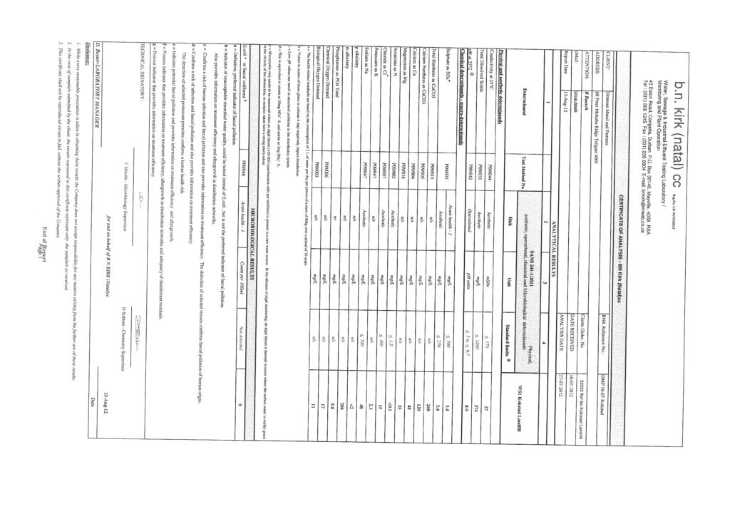
108
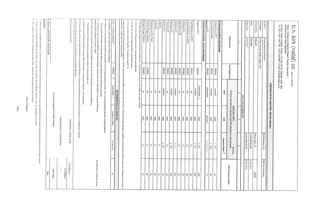
109
110 DRAWING No /1A LOCALITY PLAN


111 THE SITE DRENNAN, MAUD AND PARTNERS Consulting Civil Engineers DESIGNED : DRAWN : DATE : SCALE : CHECKED : B.R. S.P. 20/08/2012 N.T.S. LOCALITY PLAN PROPOSED LANDFILL DEVELOPMENT SITE 1 KRANTZ FONTEIN FARM, KOKSTAD REF. NO. FIG. NO A
112 DRAWING No /1B GEOLOGICAL PLAN


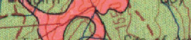

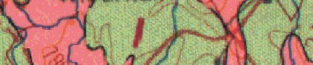
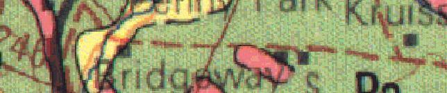

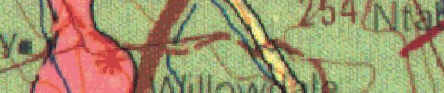
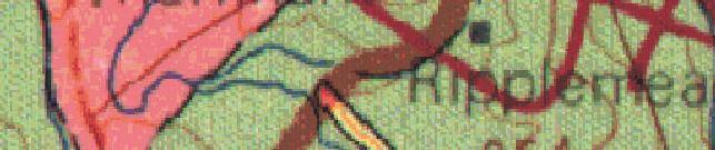


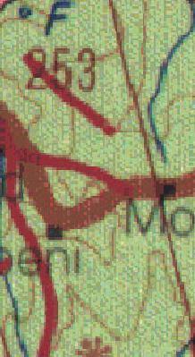


113 THE SITE TH E SITE KEY SHALE, FINE GRAINED SANDSTONE QUARTZITE (ADELAIDE FORMATION, BEAUFORT GROUP) DRENNAN, MAUD AND PARTNERS Consulting Civil Engineers KAROO DOLERITE (INTRUSIVE) DESIGNED : DRAWN : DATE : SCALE : CHECKED : B.R. S.P. 22/08/2012 N.T.S. REF. NO. GEOLOGICAL PLAN PROPOSED LANDFILL DEVELOPMENT SITE 1 KRANTZ FONTEIN FARM, KOKSTAD FIG. NO. 1B
DRENNAN, MAUD & PARTNERS
 DRENNAN, MAUD & PARTNERS Consulting Civil Engineers and Engineering Geologists Registered Member : S.A. Association of Consulting Engineers PARTNERS: R.D. COLLYER, Pr.Eng.,B.Sc.(Eng.),M.Sc.(Eng.),MSAICE.
Telephone : G. Ntaka : Fax : M. Bénet :
 Our Ref: P 24058 Your Ref: Drennan Maud cc. CK 95/54198/23 Consulting Geotechnical Engineers & Engineering Geologists VAT Reg ¹ 4770223594 P.O. Box 22997 Unit 7, Gayridge Business Park ¹ 2 MARGATE 13 Wingate
GEOLOGICAL PROCESSES AND MATERIALS SGM210
 University of Pretoria GEOLOGICAL PROCESSES AND MATERIALS SGM210 23 April 2014 1 SOIL PROFILING According to Jennings, Brink & Williams (1973) Very important part of a geotechnical site investigation.
APPENDIX 6: GEOTECHNICAL FEASIBILITY INVESTIGATION
 APPENDIX 6: GEOTECHNICAL FEASIBILITY INVESTIGATION ENVIRONMENTAL SCIENCE ASSOCIATES SAMANCOR CHROME, MIDDELBURG GEOTECHNICAL FEASIBILITY INVESTIGATION FOR NEW CHROME PLANT FACILITY J VAN TONDER (PrSciNat)
DRENNAN MAUD (PTY) LTD
 LTD") DRENNAN MAUD (PTY) LTD GEOTECHNICAL ENGINEERS AND ENGINEERING GEOLOGISTS Incorporating Drennan Maud & Partners (Est.1975) and GAP Consulting Reg. No. 2014/038872/07 Durban Head Office Info@drennanmaud.com
DRENNAN MAUD (PTY) LTD GEOTECHNICAL ENGINEERS AND ENGINEERING GEOLOGISTS Incorporating Drennan Maud & Partners (Est.1975) and GAP Consulting Reg. No. 2014/038872/07 Durban Head Office Info@drennanmaud.com
Geology and Soil Mechanics /1A ( ) Mark the best answer on the multiple choice answer sheet.
 Mark the best answer on the multiple choice answer sheet.") Geology and Soil Mechanics 55401 /1A (2003-2004) Mark the best answer on the multiple choice answer sheet. 1. Soil mechanics is the application of hydraulics, geology and mechanics to problems relating
Geology and Soil Mechanics 55401 /1A (2003-2004) Mark the best answer on the multiple choice answer sheet. 1. Soil mechanics is the application of hydraulics, geology and mechanics to problems relating
Report to Tyris Realty on a Geotechnical Investigation for a Proposed Warehouse Development at Sprite Place, Westmead
 Report to Tyris Realty on a Geotechnical Investigation for a Proposed Warehouse Development at Sprite Place, Westmead Reference : 11-358 Dated : February 2012 MOORE SPENCE JONES (PTY) LTD Consulting Geotechnical,
A. V T = 1 B. Ms = 1 C. Vs = 1 D. Vv = 1
 Geology and Soil Mechanics 55401 /1A (2002-2003) Mark the best answer on the multiple choice answer sheet. 1. Soil mechanics is the application of hydraulics, geology and mechanics to problems relating
Project No.: R01
 Report to Voigts Construction on a Geotechnical Investigation carried out for the Royal Albert Lodge, Albert Falls Dam, KwaZulu-Natal Project No.: 18-156R01 Date Issued: November 2018 Report to Voigts
REPORT NO 12/115/D NOVEMBER 2012 GEOTECHNICAL INVESTIGATION FOR THE PROPOSED SOLAR PHOTOVOLTAIC FACILITY, GROOTVLEI POWER STATION
 Consulting Geotechnical Engineers & Engineering Geologists P.O.Box 3557 Cramerview 2060. Tel: (011) 465-1699. Fax: (011) 465-4586. Cell 082 556 7302 & 076 966 8445 REPORT NO 12/115/D NOVEMBER 2012 GEOTECHNICAL
 TP-1 N61E 0 DARK BROWN SANDY SILT (ML) stiff, wet with roots (Disturbed Surficial Soil) DEPTH (FEET) 5 REDDISH BROWN SANDSTONE intensely fractured, weak to friable, deeply weathered, tight (Franciscan
 Project: ITHACA-TOMPKINS REGIONAL AIRPORT EXPANSION Project Location: ITHACA, NY Project Number: 218-34 Key to Soil Symbols and Terms TERMS DESCRIBING CONSISTENCY OR CONDITION COARSE-GRAINED SOILS (major
 Photo 1 - Southerly view across 2700 parking lot toward existing building. Multi-residential building borders western side of property in upper right of view. Photo 2 - Southerly view across 2750 parking
APPENDIX A. Borehole Logs Explanation of Terms and Symbols
 APPENDIX A Borehole Logs Explanation of Terms and Symbols Page 153 of 168 EXPLANATION OF TERMS AND SYMBOLS The terms and symbols used on the borehole logs to summarize the results of field investigation
DRENNAN MAUD (PTY) LTD
 LTD") DRENNAN MAUD (PTY) LTD GEOTECHNICAL ENGINEERS AND ENGINEERING GEOLOGISTS Incorporating Drennan Maud & Partners (Est.1975) and GAP Consulting Reg. No. 2014/038872/07 Durban Head Office Info@drennanmaud.com
DRENNAN MAUD (PTY) LTD GEOTECHNICAL ENGINEERS AND ENGINEERING GEOLOGISTS Incorporating Drennan Maud & Partners (Est.1975) and GAP Consulting Reg. No. 2014/038872/07 Durban Head Office Info@drennanmaud.com
Appendix A. Producer Statement Advisory Note
 Appendix A Producer Statement Advisory Note Ref. No. 17095 26 May 2017 PRODUCER STATEMENT CONSTRUCTION REVIEW (PS4) IMPORTANT ADVISORY NOTE The Building Consent Authority (BCA) frequently requires Producer
 SOIL CLASSIFICATION CHART COARSE-GRAINED SOILS MORE THAN 50% RETAINED ON NO.200 SIEVE FINE-GRAINED SOILS 50% OR MORE PASSES THE NO.200 SIEVE PRIMARY DIVISIONS GRAVELS MORE THAN 50% OF COARSE FRACTION RETAINED
16 January 2018 Job Number: RICHARD NEWMAN C\- CLARK FORTUNE MCDONALD AND ASSOCIATES PO BOX 553 QUEENSTOWN
 16 January 2018 Job Number: 50595 RICHARD NEWMAN C\- CLARK FORTUNE MCDONALD AND ASSOCIATES PO BOX 553 QUEENSTOWN CHANSEN@CFMA.CO.NZ STORMWATER DISPOSAL ASSESSMENT Dear Richard, RDAgritech were requested
 5.2 APPENDIX D2 Geotechnical Report Jeffares & Green: 03524: Ilinge and Lesseyton Cemetery Development ILINGE AND LESSEYTON CEMETERY DEVELOPMENT - GEOTECHNICAL INVESTIGATION FINAL REPORT SEPTEMBER 2014
DATE: 5/17/2012. LOGGED BY: Geoff Richards. COMPANY: Tetra Tech EM, Inc. DRILL FOREMAN: Walter
 ATTACHMENT 2 Page 1 of 1 B1 0 1 2 FILL, Dry; brownish red; clayey silt and gravel; ~30% gravel size fragments of dark grey microcrystalline (aphanetic), extrusive, igneous, rock 3 B1-4a 1100 B1-4b-duplicate
 5.2 APPENDIX D2 Geotechnical Report Jeffares & Green: 03524: Ilinge and Lesseyton Cemetery Development ILINGE AND LESSEYTON CEMETERY DEVELOPMENT - GEOTECHNICAL INVESTIGATION FINAL REPORT SEPTEMBER 2014
 UNIT DESCRIPTIONS: Artificial Fill, Undocumented (Afu): Locally derived sandy silt and silty sand, locally with clay and varying amounts of gravel and man-made debris. Abundant concrete rubble, in places
Hydro One (Sept 2014) Hydro One (Sept 2014) Hydro One (Sept 2014)
 Hydro One (Sept 2014) Hydro One (Sept 2014)") TABLE 1 WELL CONSTRUCTION DETAILS MOE WWR No Well ID Location Installation Date Status Easting Coordinates Northing Source Elevation Screened Interval Screened Material Borehole Well Stick-up Ground Top
TABLE 1 WELL CONSTRUCTION DETAILS MOE WWR No Well ID Location Installation Date Status Easting Coordinates Northing Source Elevation Screened Interval Screened Material Borehole Well Stick-up Ground Top
GEOTECHNICAL INVESTIGATION FOR REDHOUSE CHELSEA ARTERIAL AND WALKER DRIVE EXTENSION, PORT ELIZABETH, EASTERN CAPE
 GEOTECHNICAL INVESTIGATION FOR REDHOUSE CHELSEA ARTERIAL AND WALKER DRIVE EXTENSION, PORT ELIZABETH, EASTERN CAPE MAY 2010 Prepared for: Prepared by: BKS (PTY) LTD TERRATEST (PTY) LTD P.O. Box 272 P.O.
June 9, R. D. Cook, P.Eng. Soils Engineer Special Services Western Region PUBLIC WORKS CANADA WESTERN REGION REPORT ON
 PUBLIC WORKS CANADA WESTERN REGION REPORT ON GEOTECHNICAL INVESTIGATION PROPOSED MARTIN RIVER BRIDGE MILE 306.7 MACKENZIE HIGHWAY Submitted by : R. D. Cook, P.Eng. Soils Engineer Special Services Western
Pierce County Department of Planning and Land Services Development Engineering Section
 Page 1 of 7 Pierce County Department of Planning and Land Services Development Engineering Section PROJECT NAME: DATE: APPLICATION NO.: PCDE NO.: LANDSLIDE HAZARD AREA (LHA) GEOLOGICAL ASSESSMENT REPORT
Field Exploration. March 31, J-U-B ENGINEERS, Inc. 115 Northstar Avenue Twin Falls, Idaho Attn: Mr. Tracy Ahrens, P. E. E:
 March 31, 201 11 Northstar Avenue 83301 Attn: Mr. Tracy Ahrens, P. E. E: taa@jub.com Re: Geotechnical Data Report Preliminary Phase 1 Field Exploration Revision No. 1 Proposed Rapid Infiltration Basin
GEOTECHNICAL PHASE 1
 GEOTECHNICAL PHASE 1 FOR PROPOSED SKUKUZA SAFARI LODGE FOR KRUGER NATIONAL PARK MPUMALANGA PROVINCE SEPTEMBER 2014 Report No: G14-0902 Issue 2 Prepared by: Conic North Consulting Engineers PO Box 11862
University of Fort Hare, Alice Campus
 University of Fort Hare, Alice Campus Geotechnical Investigation COMPILED FOR: MBB Consulting Engineers P O Box 509 Grahamstown 6140 Telephone: +27 (0)46 622 7223 Facsimile: +27 (0)86 570 7844 COMPILED
Depth (ft) USCS Soil Description TOPSOIL & FOREST DUFF
 USCS Soil Description TOPSOIL & FOREST DUFF") Test Pit No. TP-6 Location: Latitude 47.543003, Longitude -121.980441 Approximate Ground Surface Elevation: 1,132 feet Depth (ft) USCS Soil Description 0 1.5 1.5 5.0 SM 5.0 8.0 SM Loose to medium dense,
Test Pit No. TP-6 Location: Latitude 47.543003, Longitude -121.980441 Approximate Ground Surface Elevation: 1,132 feet Depth (ft) USCS Soil Description 0 1.5 1.5 5.0 SM 5.0 8.0 SM Loose to medium dense,
ECoast Homes Pty Ltd: Proposed 76-lot subdivision, Penquite Road, Newstead GEOTECHNICAL ASSESSMENT 7 April 2009
 99 Attachment 11 (8 pages including this page) Interpretation of site geology and soils, laboratory test results, and generalised AS2870 classifications 100 Geological setting The proposed subdivision
APPENDIX C HYDROGEOLOGIC INVESTIGATION
 Figure B-5.7 Figure B-5.8 Preliminary Geotechnical and Environmental Report Appendix C Hydrogeologic Investigation APPENDIX C HYDROGEOLOGIC INVESTIGATION December 21, 2011 WESTSIDE SUBWAY EXTENSION PROJECT
Soil Mechanics. Chapter # 1. Prepared By Mr. Ashok Kumar Lecturer in Civil Engineering Gpes Meham Rohtak INTRODUCTION TO SOIL MECHANICS AND ITS TYPES
 Soil Mechanics Chapter # 1 INTRODUCTION TO SOIL MECHANICS AND ITS TYPES Prepared By Mr. Ashok Kumar Lecturer in Civil Engineering Gpes Meham Rohtak Chapter Outlines Introduction to Soil Mechanics, Soil
SITE INVESTIGATION 1
 SITE INVESTIGATION 1 Definition The process of determining the layers of natural soil deposits that will underlie a proposed structure and their physical properties is generally referred to as site investigation.
3.0 SUMMARY OF FINDINGS
 AECOM 500 W Jefferson St. Suite 1600 Louisville, KY 40202 www.aecom.com 502-569-2301 tel 502-569-2304 fax October 17, 2018 Big Rivers Electric Corporation Sebree Generating Station 9000 Highway 2096 Robards,
Geotechnical Data Report
 Geotechnical Data Report Downtown Greenville Future Conveyance Study December 1, 2015 Terracon Project No. 86155032 Prepared for: Prepared by: Terracon Consultants, Inc. December 1, 2015 561 Mauldin Road
ENCE 3610 Soil Mechanics. Site Exploration and Characterisation Field Exploration Methods
 ENCE 3610 Soil Mechanics Site Exploration and Characterisation Field Exploration Methods Geotechnical Involvement in Project Phases Planning Design Alternatives Preparation of Detailed Plans Final Design
5.2 APPENDIX D2 Geotechnical Report
 5.2 APPENDIX D2 Geotechnical Report Jeffares & Green: 03524: Ilinge and Lesseyton Cemetery Development ILINGE AND LESSEYTON CEMETERY DEVELOPMENT - GEOTECHNICAL INVESTIGATION FINAL REPORT SEPTEMBER 2014
Converse Consultants Geotechnical Engineering, Environmental & Groundwater Science, Inspection & Testing Services
 Converse Consultants Geotechnical Engineering, Environmental & Groundwater Science, Inspection & Testing Services July 27, 2017 Ms. Rebecca Mitchell Mt. San Antonio College Facilities Planning & Management
SLOPE STABILITY EVALUATION AND ACCEPTANCE STANDARDS
 INFORMATION BULLETIN / PUBLIC - BUILDING CODE REFERENCE NO.: LABC 7006.3, 7014.1 Effective: 01-01-2017 DOCUMENT NO.: P/BC 2017-049 Revised: 12-21-2016 Previously Issued As: P/BC 2014-049 SLOPE STABILITY
Project No: 68R3056 Client: City of Frederick Project: RFQ 14-H Future North Side Water Tank City/State: 7516 Hayward Road, Frederick, MD
 Boring: SB-1 (1 of 1) Moist, brown to orange brown CLAY and SILT, trace sand with fine weathered rock fragments. POSSIBLE FILL. Dry, orange brown sandy SILT trace clay (SM-ML). RESIDUAL SOIL : Not Surveyed
Boreholes. Implementation. Boring. Boreholes may be excavated by one of these methods: 1. Auger Boring 2. Wash Boring 3.
 Implementation Boreholes 1. Auger Boring 2. Wash Boring 3. Rotary Drilling Boring Boreholes may be excavated by one of these methods: 4. Percussion Drilling The right choice of method depends on: Ground
UNDP HARARE HOSPITAL PROPOSED NATPHARM WAREHOUSE
 UNDP HARARE HOSPITAL PROPOSED NATPHARM WAREHOUSE January 17 2016 TO CARRY OUT IN-SITU SOIL SURVEY, LABORATORY TESTS AND GEOTECHNICAL REPORTING. GEOTECHNICAL INVESTIGATIONS REPORT 1 2 Re: GEOTECHNICAL INVESTIGATIONS
patersongroup Consulting Engineers April 20, 2010 File: PG1887-LET.01R Novatech Engineering Consultants Suite 200, 240 Michael Cowpland Drive
 patersongroup April 20, 2010 File: PG1887-LET.01R Novatech Engineering Consultants Suite 200, 240 Michael Cowpland Drive Ottawa, Ontario K2M 1P6 Attention: Mr. Adam Thompson Consulting Engineers 28 Concourse
B-1 BORE LOCATION PLAN. EXHIBIT Drawn By: 115G BROOKS VETERINARY CLINIC CITY BASE LANDING AND GOLIAD ROAD SAN ANTONIO, TEXAS.
 N B-1 SYMBOLS: Exploratory Boring Location Project Mngr: BORE LOCATION PLAN Project No. GK EXHIBIT Drawn By: 115G1063.02 GK Scale: Checked By: 1045 Central Parkway North, Suite 103 San Antonio, Texas 78232
Re: Steep Slope Assessment for 2465 Waverly Drive, Blind Bay, BC; Legal Address: Lot 39, Section 18, Township 22, Range 10, Plan 25579, W6M, KDYD.
 OEL File 1563-1 May 30, 2017 Doug Wall PO Box 774 Salmon Arm, BC V1E 4N7 Re: Steep Slope Assessment for 2465 Waverly Drive, Blind Bay, BC; Legal Address: Lot 39, Section 18, Township 22, Range 10, Plan
REPORT OF PRELIMINARY GEOTECHNICAL EXPLORATION
 REPORT OF PRELIMINARY GEOTECHNICAL EXPLORATION ENKA INTERMEDIATE SCHOOL Sand Hill Road Candler, North Carolina Prepared For: BUNCOMBE COUNTY SCHOOLS Prepared By: AMEC ENVIRONMENT & INFRASTRUCTURE, INC.
SUPPLEMENTARY INVESTIGATION AND LABORATORY TESTING Aggregate Resource Evaluation Proposed Bernand Quarry San Diego County, California
 October 3, 2 Mr. Mark San Agustin Project No. 28-- Home Land Investments Document No. -92 2239 Curlew Street San Diego, CA 92 SUBJECT: SUPPLEMENTARY INVESTIGATION AND LABORATORY TESTING Aggregate Resource
ATTACHMENT A PRELIMINARY GEOTECHNICAL SUMMARY
 ATTACHMENT A PRELIMINARY GEOTECHNICAL SUMMARY Kevin M. Martin, P.E. KMM Geotechnical Consultants, LLC 7 Marshall Road Hampstead, NH 0384 603-489-6 (p)/ 603-489-8 (f)/78-78-4084(m) kevinmartinpe@aol.com
Superficial Geology Map - Slice A. Order Details: Order Number: Customer Reference: National Grid Reference: Slice: Site Area (Ha): Search Buffer (m):
: Search Buffer (m):") Superficial Geology Superficial Deposits are the youngest geological deposits formed during the most recent period of geological time, the Quaternary, which extends back about 1.8 million years from the
Superficial Geology Superficial Deposits are the youngest geological deposits formed during the most recent period of geological time, the Quaternary, which extends back about 1.8 million years from the
Prof. B V S Viswanadham, Department of Civil Engineering, IIT Bombay
 19 Module 5: Lecture -1 on Stability of Slopes Contents Stability analysis of a slope and finding critical slip surface; Sudden Draw down condition, effective stress and total stress analysis; Seismic
(C) Global Journal of Engineering Science and Research Management
 Global Journal of Engineering Science and Research Management") GEOTECHNCIAL ASSESSMENT OF PART OF PORT HARCOURT, NIGER DELTA FOR STRUCTURAL ANALYSIS Warmate Tamunonengiyeofori Geostrat International Services Limited, www.geostratinternational.com. *Correspondence
GEOTECHNCIAL ASSESSMENT OF PART OF PORT HARCOURT, NIGER DELTA FOR STRUCTURAL ANALYSIS Warmate Tamunonengiyeofori Geostrat International Services Limited, www.geostratinternational.com. *Correspondence
Geotechnical Engineering Report
 Geotechnical Engineering Report Turner Turnpike Widening Bridge B Bridge Crossing: South 257 th West Avenue Creek County, Oklahoma June 1, 2016 Terracon Project No. 04155197 Prepared for: Garver, LLC Tulsa,
GEOTECHNICAL INVESTIGATION OF RAILWAYS
 GEOTECHNICAL INVESTIGATION OF RAILWAYS Prof. Hannes Gräbe University of Pretoria Transnet Chair in Railway Engineering May 2011 Contents Cost considerations Objectives Phased approach to site investigation
ENGINEER S CERTIFICATION OF FAULT AREA DEMONSTRATION (40 CFR )
") PLATTE RIVER POWER AUTHORITY RAWHIDE ENERGY STATION BOTTOM ASH TRANSFER (BAT) IMPOUNDMENTS LARIMER COUNTY, CO ENGINEER S CERTIFICATION OF FAULT AREA DEMONSTRATION (40 CFR 257.62) FOR COAL COMBUSTION RESIDUALS
PLATTE RIVER POWER AUTHORITY RAWHIDE ENERGY STATION BOTTOM ASH TRANSFER (BAT) IMPOUNDMENTS LARIMER COUNTY, CO ENGINEER S CERTIFICATION OF FAULT AREA DEMONSTRATION (40 CFR 257.62) FOR COAL COMBUSTION RESIDUALS
14 Geotechnical Hazards
 Volume 2: Assessment of Environmental Effects 296 14 Geotechnical Hazards Overview This Chapter provides an assessment of the underlying geotechnical conditions to identify: any potential liquefaction
BKS Palace Consortium conducted the geotechnical investigation for the proposed pumped storage scheme (PSS) in the Steelpoort area.
 in the Steelpoort area.") 6. GEOLOGY 6.1 Introduction The high-lying Nebo Plateau to the west of the Steelpoort Valley comprises gently undulating terrain at elevations of around 1700m at the upper reservoir site. To the east,
6. GEOLOGY 6.1 Introduction The high-lying Nebo Plateau to the west of the Steelpoort Valley comprises gently undulating terrain at elevations of around 1700m at the upper reservoir site. To the east,
Geotechnical Data Report
 Geotechnical Data Report ReWa Solar Farm at Durbin Creek Fountain Inn, South Carolina September 1, 2017 Terracon Project No. 86165043 Prepared for: Renewable Water Resources Greenville, South Carolina
Proposed Cemetery Thornhill Road. Tier One Hydrogeological Risk Assessment. Peter Mitchell Associates
 Proposed Cemetery Thornhill Road Tier One Hydrogeological Risk Assessment Peter Mitchell Associates January 2015 Executive Summary This report uses a desk-based risk assessment technique published by the
Soil Mechanics Brief Review. Presented by: Gary L. Seider, P.E.
 Soil Mechanics Brief Review Presented by: Gary L. Seider, P.E. 1 BASIC ROCK TYPES Igneous Rock (e.g. granite, basalt) Rock formed in place by cooling from magma Generally very stiff/strong and often abrasive
MERCURY - PERSEUS TRANSMISSION LINE ENGINEERING GEOLOGICAL ASSESSMENT FOR ROUTE 1
 MERURY - PERSEUS TRANSMISSION LINE ENGINEERING GEOLOGIAL ASSESSMENT FOR ROUTE 1 Prepared by: I KLEINHANS KNIGHT HALL HENDRY P.O. Box 72292 Lynnwood Ridge 0040 Prepared for: STRATEGI ENVIRONMENTAL FOUS
Appendix G GEOLOGICAL INVESTIGATION
 Appendix G GEOLOGICAL INVESTIGATION JOB NUMBER: 3268.001 DATE: 10-14-13 BY: CC SITE 0 2000 1"=2000' VICINITY MAP CARGILL PARCEL HICKORY STREET AND ENTERPRISE DRIVE NEWARK, CALIFORNIA FOR
SOIL REPORT FOR BINGARA GORGE DEVELOPMENT SITE Introduction
 SOIL REPORT FOR BINGARA GORGE DEVELOPMENT SITE Introduction On 16 March, 1 April 2016 and 21 September 2016 I undertook soil surveys at Bingara Gorge Development Site, Wilton, and prepared this soil report
Geotechnical verification of impact compaction
 PII-73 Geotechnical verification of impact compaction P. J. Waddell1, R. A. Moyle2 & R. J. Whiteley1 1 2 Coffey Geotechnics, Sydney, Australia Coffey Geotechnics, Harrogate, UK Abstract Remediation of
Geotechnical Engineering Report
 Geotechnical Engineering Report Turner Turnpike Widening Polecat Creek Bridge (Bridge A) June 1, 2016 Terracon Project No. 04155197 Prepared for: Garver, LLC Prepared by: Terracon Consultants, Inc. TABLE
Report of Preliminary Geotechnical Exploration. CSO-012 Sewer Separation Cincinnati, Hamilton County, Ohio. February, 2011
 11242843_GeoTech_Preliminary - Feburary 2011_1/40 Report of Preliminary Geotechnical Exploration CSO-012 Sewer Separation Cincinnati, Hamilton County, Ohio February, 2011 11242843_GeoTech_Preliminary -
J. Paul Guyer, P.E., R.A.
 J. Paul Guyer, P.E., R.A. Paul Guyer is a registered mechanical engineer, civil engineer, fire protection engineer and architect with over 35 years experience in the design of buildings and related infrastructure.
3.12 Geology and Topography Affected Environment
 3 Affected Environment and Environmental Consequences 3.12 Geology and Topography 3.12.1 Affected Environment 3.12.1.1 Earthquakes Sterling Highway MP 45 60 Project Draft SEIS The Kenai Peninsula is predisposed
Reference: R01. Dated: 18 July 2013 LEVEL 1 BEE SUPPLIER
 Geotechnical Engineering Services Engineering Geology Environmental and Groundwater Pile Integrity Testing Civil Engineering Laboratory Earthworks/Materials Supervision & Control Geotechnical Monitoring
GEOTECHNICAL REPORT. Matanuska-Susitna Borough. Parks Highway Connections Museum Drive. Matanuska-Susitna Borough, Alaska.
 Matanuska-Susitna Borough GEOTECHNICAL REPORT Parks Highway Connections Museum Drive Matanuska-Susitna Borough, Alaska March 2, 20 Prepared By: John Thornley, PE Geotechnical Engineer 333 Arctic Blvd.,
Converse Consultants Geotechnical Engineering, Environmental & Groundwater Science, Inspection & Testing Services
 Converse Consultants Geotechnical Engineering, Environmental & Groundwater Science, Inspection & Testing Services Ms. Rebecca Mitchell Mt. San Antonio College Facilities Planning & Management 1100 North
SOIL AND AGGREGATE FUNDAMENTALS STUDENT GUIDE AMRC April, 2006 AREA MANAGER ROADS CERTIFICATION PROGRAM FOR EDUCATIONAL PURPOSES ONLY
 AREA MANAGER ROADS CERTIFICATION PROGRAM AMRC 2011 SOIL AND AGGREGATE FUNDAMENTALS STUDENT GUIDE FOR EDUCATIONAL PURPOSES ONLY April, 2006 WPC #28013 07/09 2009 by British Columbia Institute of Technology
Ardaman & Associates, Inc. Geotechnical, Environmental and Materials Consultants
 SUBSURFACE SOIL EXPLORATION DRAINAGE IMPROVEMENTS TO THE HENDRY COUNTY, FLORIDA Ardaman & Associates, Inc. Geotechnical, Environmental and Materials Consultants OFFICES Orlando, 88 S. Orange Avenue, Orlando,
Gotechnical Investigations and Sampling
 Gotechnical Investigations and Sampling Amit Prashant Indian Institute of Technology Gandhinagar Short Course on Geotechnical Investigations for Structural Engineering 12 14 October, 2017 1 Purpose of
APPENDIX A GEOTECHNICAL REPORT
 The City of Winnipeg Bid Opportunity No. 529-2017 Template Version: C420170317 - RW APPENDIX A GEOTECHNICAL REPORT Quality Engineering Valued Relationships KGS Group 2017 Industrial Street Rehabilitation
Safe bearing capacity evaluation of the bridge site along Syafrubesi-Rasuwagadhi road, Central Nepal
 Bulletin of the Department of Geology Bulletin of the Department of Geology, Tribhuvan University, Kathmandu, Nepal, Vol. 12, 2009, pp. 95 100 Safe bearing capacity evaluation of the bridge site along
Chapter 12 Subsurface Exploration
 Page 12 1 Chapter 12 Subsurface Exploration 1. The process of identifying the layers of deposits that underlie a proposed structure and their physical characteristics is generally referred to as (a) subsurface
Geotechnical Engineering Report
 Geotechnical Engineering Report Richland Creek Trunk Sewer Greenville, South Carolina March 31, 2014 Terracon Project No. 86145008 Prepared for: Renewable Water Resources Greenville, South Carolina Prepared
Central Queensland Coal Project Appendix 4b Geotechnical Assessment. Environmental Impact Statement
 Central Queensland Coal Project Appendix 4b Geotechnical Assessment Environmental Impact Statement GEOTECHNICAL ASSESSMENT OF OPEN CUT MINING ADJACENT TO THE BRUCE HIGHWAY, CENTRAL QUEENSLAND COAL PROJECT
Landslide stability analysis using the sliding block method
 Landslide stability analysis using the sliding block method E. Lino, R. Norabuena, M. Villanueva & O. Felix SRK Consulting (Peru) S.A., Lima, Peru A. Lizcano SRK Consulting (Vancouver) S.A., British Columbia,
Mass Wasting. Revisit: Erosion, Transportation, and Deposition
 Mass Wasting Revisit: Erosion, Transportation, and Deposition While landslides are a normal part of erosion and surface processes, they can be very destructive to life and property! - Mass wasting: downslope
Connecticut's Aquifers
 Page 1 of 5 DEP Search: Connecticut's Aquifers The technical definition of the word "aquifer" is: any geologic formation capable of yielding significant quantities of water to wells. By that definition,
December 5, Junction Gateway, LLC 7551 W. Sunset Boulevard #203 Los Angeles, CA Mr. James Frost P: Dear Mr.
 December 5, 2014 Junction Gateway, LLC 7551 W. Sunset Boulevard #203 90046 Attn: Re: Mr. James Frost P: 323.883.1800 Geotechnical Update Letter Sunset & Effie Mixed Use Development 4301 to 4311 Sunset
patersongroup Design for Earthquakes Consulting Engineers May 19, 2016 File: PG3733-LET.01
 patersongroup May 19, 2016 File: PG3733-LET.01 Hydro Ottawa Limited c/o Cresa Toronto 170 University Avenue, Suite 1 Toronto, Ontario M5H 3B3 Attention: Ms. Barbara Wright Consulting Engineers 154 Colonnade
ARCH 1250 APPLIED ENVIRONMENTAL STUDIES
 John Seitz, RA, LEED AP Assistant Adjunct Professor Professor Paul C. King, RA, AIA, ARA Assistant Professor Geology Geology is the scientific study of the structure and composition of the earth s surface
REPORT. Housing Re-Zone. Middle Road and Iona Road - Geotechnical Investigation Report
 REPORT Housing Re-Zone Middle Road and Iona Road - Geotechnical Investigation Report Prepared for Hastings istrict Council Prepared by Tonkin & Taylor Ltd ate April 06 Job Number 464.000 istribution: Hastings
Civil Engineering, Surveying and Environmental Consulting WASP0059.ltr.JLS.Mich Ave Bridge Geotech.docx
 2365 Haggerty Road South * Canton, Michigan 48188 P: 734-397-3100 * F: 734-397-3131 * www.manniksmithgroup.com August 29, 2012 Mr. Richard Kent Washtenaw County Parks and Recreation Commission 2330 Platt
Lake Rotoiti Wastewater Scheme - Stage 1 Investigations. Rotorua Lakes Council
 Lake Rotoiti Wastewater Scheme - Stage 1 Investigations Rotorua Lakes Council i Contents 1 Introduction...1 2 Site Description...1 3 Geological Setting...1 4 Geotechnical Investigation...1 4.1 Borehole
Cape Cross Salt Works PO Box 81307, Windhoek, Namibia. FINAL REPORT rev1 NHN170 NOVEMBER 2016
 Cape Cross Salt Works PO Box 81307, Windhoek, Namibia GROUNDWATER EXPLORATION FOR SUPPLY TO THE CAPE CROSS SALT WORKS FINAL REPORT rev1 NHN170 NOVEMBER 2016 Namib Hydrosearch, PO Box 11546 Windhoek Namibia,
3.0 GEOLOGY AND HYDROGEOLOGY
 3.0 GEOLOGY AND HYDROGEOLOGY 3.1 Methodology The Geological Survey of Ireland (GSI) publication Geology of South Cork was consulted to establish the nature of the bedrock lithology and Quaternary sediments.
APPENDIX C. Borehole Data
 APPENDIX C Borehole Data MAJOR DIVISIONS SOIL CLASSIFICATION CHART SYMBOLS GRAPH LETTER TYPICAL DESCRIPTIONS ADDITIONAL MATERIAL
Geotechnical Engineering Report
 Geotechnical Engineering Report Turner Turnpike Widening Bridge D Bridge Crossing: South 209 th West Avenue Creek County, Oklahoma June 1, 2016 Terracon Project No. 04155197 Prepared for: Garver, LLC Tulsa,
patersongroup Mineral Aggregate Assessment 3119 Carp Road Ottawa, Ontario Prepared For Mr. Greg LeBlanc March 7, 2014 Report: PH2223-REP.
 Geotechnical Engineering Environmental Engineering group Hydrogeology Geological Engineering Archaeological Studies Materials Testing 3119 Carp Road Prepared For Mr. Greg LeBlanc March 7, 2014 Paterson
6.2 Geotechnical Investigation and Construction Material Survey
 6.2 Geotechnical Investigation and Construction Material Survey Geological surveys and investigations were conducted to obtain information on the subsurface geological condition required for the preliminary
M E M O R A N D U M. Mr. Jonathan K. Thrasher, P.E., Mr. Ian Kinnear, P.E. (FL) PSI
 PSI") M E M O R A N D U M TO: FROM: Mr. Mark Schilling Gulf Interstate Engineering Mr. Jonathan K. Thrasher, P.E., Mr. Ian Kinnear, P.E. (FL) PSI DATE: November 11, 2014 RE: Summary of Findings Geotechnical
M E M O R A N D U M TO: FROM: Mr. Mark Schilling Gulf Interstate Engineering Mr. Jonathan K. Thrasher, P.E., Mr. Ian Kinnear, P.E. (FL) PSI DATE: November 11, 2014 RE: Summary of Findings Geotechnical
Reference No S072 APRIL 2012
 A REPORT TO SOLMAR DEVELOPMENT CORP. A PRELIMINARY SOIL INVESTIGATION FOR PROPOSED SUBDIVISION DEVELOPMENT NORTHEAST OF SIDEROAD 5 AND 0 LINE TOWN OF ERIN Reference No. 202-S072 APRIL 202 DISTRIBUTION
REPORT ON THE ASSESSMENT OF TRENCHING INTHE ROAD RESERVE OF THE ROAD BETWEEN BEAUFORT WEST AND CARNAVON.
 Contract Report CSIR/BE/TIE/SKA/59E2214 August 2018 REPORT ON THE ASSESSMENT OF TRENCHING INTHE ROAD RESERVE OF THE ROAD BETWEEN BEAUFORT WEST AND CARNAVON. Authors: Dave Ventura Anele Sambo Michael Roux
Site Investigation and Landfill Construction I
 Site Investigation and Landfill Construction I Gernot Döberl Vienna University of Technology Institute for Water Quality, Resources and Waste Management Contents Site Investigation Base Liners Base Drainage
PRINCIPLES OF GEOTECHNICAL ENGINEERING
 PRINCIPLES OF GEOTECHNICAL ENGINEERING Fourth Edition BRAJA M. DAS California State University, Sacramento I(T)P Boston Albany Bonn Cincinnati London Madrid Melbourne Mexico City New York Paris San Francisco
BR-01 PAINT BRIDGE NO. 55 C GENERAL PLAN 720'-0" VC 605'-0" VC 1. FOR INDEX TO PLANS, QUANTITIES, AND GENERAL NOTES, SEE "INDEX TO PLANS" SHEET.
 2'-" VC 6'-" VC BB EB 1 1 1 1 1 TV - " TV CONDUITS (COX E 8 - " ELECTRIC CONDUITS (SDG & E T - " TELEPHONE CONDUITS 1. FOR INDEX TO PLANS, QUANTITIES, AND GENERAL NOTES, SEE "INDEX TO PLANS" SHEET. 2.