DEFENSE MAPPING AGENCY TECHNICAL MANUAL DATUMS, ELLIPSOIDS, GRIDS, AND GRID REFERENCE SYSTEMS
|
|
|
- Miles Barber
- 6 years ago
- Views:
Transcription
1
2 DEFENSE MAPPING AGENCY TECHNICAL MANUAL DATUMS, ELLIPSOIDS, GRIDS, AND GRID REFERENCE SYSTEMS Abstract: This manual describes the basic principles of the Military Grid Reference System and the nonstandard reference systems. It describes the method for determining references on maps and charts at scales of 1:1,000,000 and larger. It contains identifications for the grid zone designations and for the 100,000 meter squares of the Universal Transverse Mercator Grid and the Universal Polar Sterographic Grid. It also contains the specifications and grid identifications for the various non-standard grids. It provides diagrams and textual information for delineating geodetic datums and ellipsoids. Subject Terms: Position location, military grid, geodetic datum, coordinate reference system, ellipsoid, spheroid, graticule, chart, projection.
3 DEFENSE MAPPING AGENCY MISSION: To enhance national security and support the Office of the Secretary of Defense, the Joint Chiefs of Staff, Unified and Specified Commands, Military Departments, and other users, by producing and distributing timely and tailored mapping, charting, and geodetic products, services, and training, and advising on such matters. To provide nautical charts and marine navigational data to worldwide merchant marine and private vessel operators. To maintain liaison with civil agencies and other national and international scientific and other mapping, charting, and geodetic activities.
4 DEFENSE MAPPING AGENCY 8613 LEE HIGHWAY FAIRFAX, VIRGINIA SEP 1990 DEFENSE MAPPING AGENCY TECHNICAL MANUAL DATUMS, ELLIPSOIDS, GRIDS, AND GRID REFERENCE SYSTEMS FOREWORD 1. This manual states current authoritative guidance for the use and portrayal of grids and grid reference systems information as applicable to maps and charts compiled for the United States Department of Defense (DoD). 2. This publication contains no copyrighted material and has been approved for public release. Distribution is unlimited. DoD users may order copies from the Defense Mapping Agency Combat Support Center, ATTN: PMSR, Washington, D.C All other requests should be directed to the National Technical Information Center, Cameron Station, Alexandria, VA STANLEY O. SMITH Brigadier General, USAF Chief of Staff
5 DMA TM FRONT MATTER FOREWORD LIST OF FIGURES LIST OF TABLES CHAPTER 1 GENERAL CONTENTS Authority References Purpose Scope Utilization Definitions Reference Systems Standard and Nonstandard Grids Multiple Grids Overlapping Grids Extended Grids Grid and Datum Related Marginal Notes Supercession CHAPTER 2 DATUMS, ELLIPSOIDS, PROJECTIONS AND MILITARY GRIDS General Horizontal Datums Transforming Coordinates from one Horizontal Datum to Another Horizontal Datum Ellipsoids Projections Military Grids Transforming Coordinates from one Grid System to Another Grid System
6 CHAPTER 3 THE U. S. MILITARY GRID REFERENCE SYSTEM (MGRS) General Description The Grid Zone Designation ,000-Meter Square Identification The Military Grid Reference MGRS Application CHAPTER 4 THE NONSTANDARD GRID SYSTEMS IN CURRENT USE PAGE Nonstandard Grids on Maps and Charts Diagrams of Nonstandard Grids CHAPTER 5 GEOGRAPHIC COORDINATE REFERENCES Use The Geographic Reference Geographic Coordinates on Maps and Charts The World Geographic Reference System CHAPTER 6 PORTRAYAL OF GRIDS ON MAPS AT 1:100,000 SCALE AND LARGER General The Major Grid Multiple Major Grids Overlapping Grids Secondary Grids The Declination Diagram (One Grid) The Declination Diagram (More Than One Grid) The Grid Reference Box CHAPTER 7 PORTRAYAL OF GRIDS ON MAPS AT 1:250,000 AND 1:500,000 SCALE General The Major Grid
7 7-3 - Multiple Major Grids Overlapping and Extended Grids Secondary Grids Grid Declination Magnetic Dechnotion The Grid Reference Box CHAPTER 8 PORTRAYAL OF GRIDS ON MAPS AT 1:1,000,000 SCALE General The Major Grid Multiple Major Grids Overlapping, Extended, and Secondary Grids Grid and Magnetic Declinations The Grid Reference Box CHAPTER 9 GRIDS ON NAUTICAL CHARTS AT 1:75,000 SCALE AND LARGER General The Major Grid on Combat Charts and Amphibious Assault Charts The Major Grid on Mine Warfare Charts The Major Grid on Harbor, Approach, and Coastal Charts Multiple Major Grids on Combat Charts and Amphibious Assault Charts Multiple Major Grids on Harbor, Approach, and Coastal Charts Overlapping Grids on Combat Charts, Amphibious Assault Charts, and Mine Warfare Charts Overlapping Grids on Harbor, Approach, and Coastal Charts Secondary Grids The Declination Note The Grid Reference Box World Geodetic System (WGS) Datum Note CHAPTER 10 GRIDS ON NAUTICAL CHARTS AT SCALES SMALLER THAN
8 175, General The Major Grid Multiple Grids Secondary Grids The Grid Reference Box (or Notes) World Geodetic System (WGS) Datum Note CHAPTER 11 GRIDS ON AERONAUTICAL CHARTS AT 1-500,000 SCALE AND LARGER General The Major Grid Grid Declination Magnetic Declination The Grid Reference Box APPENDIXES A - Table of Mil Equivalents *B - 100,000-Meter Square Identifications of the Military Grid Reference System (Graphics), Figures B-1 through B-4 *C - Guide To Geodetic Status Of Large Scale Mapping *D -Index to Preferred Grids, Datums and Ellipsoids Specified for New Mapping * Requires periodic update and revision.
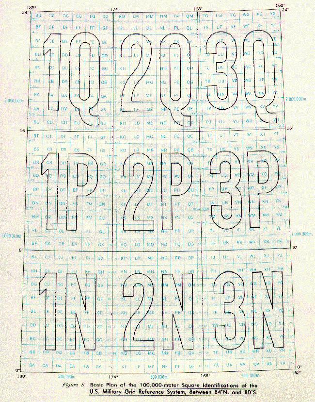
9 LIST OF FIGURES 1 Defining Parameters of Ellipsoids 2 Mercator Projection 3 Transverse Mercator Projection 4 Secant Condition of Transverse Mercator Projection; Typical 6-degree Projection Zone 5 Polar Stereographic Projection 6 Lambert Conformal Conic Projection 7 Grid Zone Designations of the Military Grid Reference System 8 Basic Plan of the 100,000-meter Square Identifications of the U.S. Military Grid Reference System, Between 84 N. and 80 s. 9 Method of Reading a U.S. Military Grid Reference from a 1:250,000 Scale Map 10 Method of Reading a U.S. Military Grid Reference from a Large Scale Map 11 Normal Lettering Plan of the 500, ,000-unit squares of the British Grid System 12 World Geographic Reference (GEOREF) System 13 The Major Grid as Shown a 1:50,000 Scale Map 14 The Major Grid as Shown on a 1:100,000 Scale Map 15 Two Major Grids (in this case, Zones of the UTM) Separated 16 Three Major Nonstandard Grids as Shown on a Large Scale Map 17 Major and Overlapping Grids as Shown on a Large Scale 18 Overlapping Grid in Combination with Two Major Grids Separated by a Grid Junction as Shown on a Large Scale Map 19 Major and Secondary (Obsolete) Grids as Shown on a Large Scale Map 20 The Declination Diagram and Accompanying Notes with True North Appearing as the Center Prong 21 The Declination Diagram and Accompanying Notes with True North Appearing as an Outside Prong 22 The Declination Data when a Sheet Contains an Overlapping rid and/or More Than One Major Grid 23 Grid Reference Boxes Most Commonly Used on Maps at Coles of 1:100,000 and Larger 24 Methods of Showing Grid Zone Designations and 100,000- meter Squares of the UTM in the Grid Reference Boxes of Large Scale Maps 25 Methods of Showing 100,000-unit, and Larger, Square Identifications of Nonstandard Grids in the Grid Reference Boxes of Large Scale Maps 26 Treatment for the Major Grid in UTM Areas as Shown on a 1:250,000 Map 27 Treatment for the Major Grid in UTM Areas as Shown on Maps Smaller than 1:250,000 Scale and Larger than 1:1,000, Two Major UTM Grid Zones Separated by a Grid Junction as Shown on a i:250,000 Scale Map 29 Three Major Nonstandard Grids Separated by Grid Junctions 30 Two Major Grids (UTM) Separated by an Ellipsoid Junction as Shown on a 1:250,000 Scale Map 31 Treatment when Grid Falls within More than One UTM Grid Zone Designation Area as Shown on a 1:250,000 Scale Map 32 Major and Secondary (Obsolete) Grids as Shown on a 1:250,000 Scale Map 33 Grid Reference Boxes Most Commonly Used on Maps at 1:250,000 and 1:500,000 Scale 34 Treatment for the Major Grid in UTM Areas as Shown on Maps at 1:1,000,000 Scale 35 Two Major Grids (in this case, Zones of the UTM) Separated by a Grid Junction, as Shown on a Map at 1:1,000,000 Scale 36 Three Major Nonstandard Grids as Shown on a Map at 1:1,000,000 Scale 37 Grid Reference Box for 1:1,000,000 Scale Map 38 The Major Grid as Shown on Combat, Amphibious Assault Charts 39 Two Major Grids (in this case, Zones of the UTM) Separated by a Grid Junction as Shown on Combat, Amphibious Assault Charts 40 Treatment for the Major Grid on Mine Warfare Charts at 1:75,000 Scale and Larger 41 Treatment for the Major Grid on Harbor and Approach Charts at 1:75,000 Scale and Larger 42 Treatment for the Multiple Major Grids on Harbor and Approach Charts at 1:75,000 scale and Larger 43 Grid Reference Boxes Commonly Used on Nautical Charts at Scales of 1:75,000 and Larger 44 Treatment for the Major Grid on Nautical Charts at Scales Smaller than 1:75,000
10 45 Treatment for Multiple Grids on Nautical Charts at Scales Smaller than 1:75, Treatment for Major and Secondary Grids on Nautical Charts at Scales Smaller than 1:75, Grid Reference Box Commonly Used on Aeronautical Charts at 1:500,000 Scale and Larger
11 LIST OF TABLES 1 Geodetic Datums Used in Map Production 2 Molodenskiy Transformation Constants to Convert from Local Datum to WGS 84 3 Characteristics of Projections 4 Grid Unit Intervals for Various Scale Topographic Maps 5 Dimensions of Grid Zone Designation Areas 6 Specifications for Secondary Grids 7 Corner Labeling on Topographic Maps 8 The Equivalents of 40 Kilometers when Measured Along a Given Parallel of Latitude Expressed in Degrees, Minutes, and Seconds of Longitude 9 Maximum Acceptable Deviation of the Constructed Grid from the True Grid
12 CHAPTER I GENERAL 1-1 AUTHORITY. This document is issued under the authority delegated by DoD Directive , subject: Defense Mapping Agency (DMA), 12 December REFERENCES The DMA TM series replaces the DA TM series of manuals JCS-MOP 88, Position Reference Procedures, 8 May STANAG 2211, subject: Geodetic Datums, Ellipsoids, Grids, and Grid References STANAG 3676, subject: Marginal Information on Land Maps and Aeronautical Charts QSTAG 544, subject: Geodetic Datums, Spheroids, Grids, and Grid References IHO Circular Letter 9, International Horizontal Datum for Chart Reference, 15 March IHO Circular Letter 28, Transformation Notes, WGS-84, 15 July IHO Circular Letter 46, International Horizontal Datum for Chart Reference, 16 December IHO Circular Letter 18, Indication on Charts of Relationship of Horizontal Datum to Worldwide and Other Datums, 17 May IHO Circular Letter 46, Indication on Charts of Relationship of Horizontal Datum to Worldwide and Other Datums, 14 December DMA TM The Universal Grids: Universal Transverse Mercator (UTM) and Universal Polar Stereographic (UPS) DMA TR (and supplements) Department of Defense World Geodetic System PURPOSE This manual provides guidance to DoD Mapping, Charting and Geodesy (MC&G) production elements, product users, and system developers on the application of datums, ellipsoids, grids, and grid reference systems within the DoD It describes the standard methods for selecting and portraying grids orf maps and charts at scales of 1:1,000,000 and larger. Descriptions are based on the following categories Topographic Maps Hydrogrophic Charts Aeronautical Charts.
13 1-4 SCOPE This manual specifies the use of geodetic datums, ellipsoids, grids and grid reference systems used in the production of maps and charts for the DoD. The Universal Transverse Mercator an d Universal Polar Stereographic grids, the Military Grid Reference System, and nonstandard grid reference systems are described Detailed instructions and formats for grid depictions and labeling, grid margin data, declination data, etc. are contained in the DMA product specifications for approved topographic, hydrographic, and aeronautical products. 1-5 UTILIZATION TM is to be used by DoD MC&G production elements, product users, and DoD system developers in the application of datums, ellipsoids, grids, and grid reference systems Users are cautioned that the information contained herein applies to current and future MC&G production, and does not necessarily apply to products that are currently available through the DoD supply system. 1-6 DEFINITIONS Major Grid. The primary grid or grids on a map or chart Military Grid Reference System (MGRS). The alphanumeric position reporting system used by U.S. military. A full description is provided in Chapter Nonstandard Grids. Grids other than UTM and UPS, such as Ceylon Belt, India Zone IIA, West Malaysian RSO (Metric) Grid, etc Operational Grid. A grid in current operational use. Generally this would be the preferred grid but could be a previously prescribed grid Overlapping Grid. A major grid from a neighboring area primarily intended to facilitate military surveying anti fire-control Preferred Grid. The grid designated by the DoD for production of new maps, charts, and digital geographic data; and shown on the "Index to Preferred Grids, Datums, and Ellipsoids Specified for New Mapping" (Appendix D) Prescribed Grid. The grid that is locally prescribed, by the country of origin or military commander Primary Grid. The major, or principal, grid on a map or chart Secondary Grid. Any grid, other than the primary grid, required for combined operations application. Tick marks along the neat lines are the preferred method of portrayal. Such grids should remain on the maps or charts so long as the secondary grid remains in use Standard Grids. The Universal Transverse Mercator (UTM) grid and the Universal Polar Stereographic (UPS) grid World Geographic Reference System (GEOREF). A worldwide position reference system that may be applied to any map or chart graduated in latitude and longitude regardless of projection. It provides a method of expressing positions in a form suitable for reporting and plotting. The primary use is for interservice and interallied reporting of aircraft and air target positions Other Key Terms.
14 Bleeding Edge. That edge of a map or chart on which cartographic detail is extended beyond the neatline to the edge of the sheet Coordinate Reference Notation Grid coordinates are given in terms of linear in meters. Geographic coordinates are given in terms of angular measurement, usually in degrees, minutes, and seconds but occasionally in grads Datum. As used in this manual, datum refers to the geodetic or horizontal datum. The classical datum is defined by a minimum of five elements giving the position of the origin (two elements), the orientation of the network (one element), and the parameters of a reference ellipsoid (two elements). More recent definitions express the position and orientation as functions of the deviations in the meridian and in the prime vertical, the geoidellipsoid separation, and the parameters of a reference ellipsoid. The World Geodetic System is a geocentric system that provides a basic reference frame and geometric figure for the earth, models the earth gravimetrically, and provides the means for relating positions on various datums to an earth-centered, earth fixed coordinate system Easting. Eastward (that is left to right) reading of grid values on a map Ellipsoid. An ellipsoid is a mathematical figure generated by the revolution of of an ellipse about one of its axes. The ellipsoid that approximates the geoid is an ellipse rotated about its minor axis, or an oblate spheroid False Easting. A value assigned to the origin of eastings, in a grid coordinate system, to avoid the convenience of using negative coordinates False Northing. A value assigned to the origin of northings, in a grid coordinate system, to avoid the inconvenience of using negative coordinates Geoid. The equipotential surface in the gravity field of the Earth which approximates the undisturbed mean sea level extended continuously through the continents. The direction of gravity is perpendicular to the geoid at every point. The geoid is the surface of reference for astronomic observations and for geodetic leveling Graticule. A network of lines representing parallels of latitude and meridians of longitude forming a map projection Grid. Two sets of parallel lines intersecting at right angles and forming squares; a rectangular Cartesian coordinate system that is superimposed on maps, charts, and other similar representations of the earth s surface in an accurate and consistent manner to permit identification of ground locations with respect to other locations and the computation of direction and distance to other points Isogonic Line. A line drawn on a map or chart joining points of equal magnetic declination for a given time. The line connecting points of zero declination is the agonic line. Lines connecting points of equal annual change are isopors. The Magnetic Variation chart for the current 5-year epoch is available from the DMACSC Loxodrome. A line on the surface of the Earth cutting all meridians at the same angle, a rhumb line Map Projection. An orderly system of lines on a plane representing a corresponding sytem of imaginary lines on an adopted terrestrial datum surface. A map projection may be derived by geometrical construction or by mathematical analysis Neatline. The lines that bound the body of a map, usually parallels and meridians (but may be conventional or arbitrary grid lines); also called sheet lines.
15 Northing. Northward (that is from bottom to top) reading of grid values on a map Sheroid. A mathematical figure closely approaching the geoid in form and size. Ellipsoid will be used in this manual. 1-7 REFERENCE SYSTEMS Rectangular grid reference systems are usually shown on military maps and chart at scales of 1:1,000,000 and larger. Maps and charts at all scales show the geographic graticule. Maps and aeronautical charts at 1:250,000 scale and smaller show the GEOREF The Military Grid Reference System is described in Chapter Grid reference systems used with operational nonstandard grids are described in Chapter The geographic coordinates are described in Chapter STANDARD AND NONSTANDARD GRIDS The standard grid for polar areas north of 84 north, and south of 80 south, is the Universal Polar Stereographic (UPS) grid Between 84 north and 80 south, the standard grid is the Universal Transverse Mercator (UTM) grid. Other grid systems are being phased out. The long term objective is to convert the mapping of all areas of the world to UTM and UPS grids Normally, grids are not portrayed on maps at scales smaller than 1:1,000, MULTIPLE GRIDS. The use of military grids presents complex conditions in junction areas, i.e., grid zone junctions within a grid system, grid junctions between various grid systems, datum junctions, and junctions between ellipsoids. Despite this complexity, these conditions lend themselves to a uniform graphical treatment of the grids with differences in grid orientation and grid color, labels, and values. The treatment of grids under various junction conditions is prescribed in later chapters of this manual OVERLAPPING GRIDS. Maps at scales of 1:100,000 and larger, falling within approximately 40 kilometers of a grid junction, datum junctions or ellipsoid junction, usually show the adjacent (overlapping) grid by ticks and values around the neatline. In some instances, a coordinate conversion note may be used instead of an overlapping grid EXTENDED GRIDS. An extended grid is form of overlapping grid used on city maps. It provides total coverage of a map on a single grid when a portion of the map falls on an adjacent grid. The major grid is extended to cover the adjacent area and is shown by full lines GRID AND DATUM RELATED MARGINAL NOTES. Marginal notes on maps and charts should include projection, ellipsoid, grid zone or belt, horizontal datum, and magnetic declination data. Specific treatment of these items on each product is covered in the various product specifications.
16 1-13 SUPERCESSION. This document supercedes DMA , Preliminary Edition.
17 CHAPTER 2 DATUMS, ELLIPSOIDS, PROJECTIONS AND MILITARY GRIDS 2-1 GENERAL The Earth is not a sphere, but an ellipsoid, flattened slightly at the poles and bulging somewhat at the Equator. The ellipsoid is used as a surface of reference for the mathematical reduction of geodetic and cartographic data A map projection is the systematic drawing of lines representing the meridians and parallels (the graticule) on a flat surface. Different projections have unique characteristics and serve differing purposes. They are depicted by projecting the graticule of the ellipsoid onto a plane; the intersections of the graticule are computed in terms of the ellipsoid U.S. Military maps use the sexagesimal system of angular measurement (the division of a full circle into 360 ) for designating the values of the graticule. A degree is divided into 60 minute, and each minute into 60 seconds. Parallels are numbered north and south from O at the equator to 90 at the poles. Meridians are numbered east and west from O at the prime meridian to a common 180 meridian. The prime meridian used for U.S. Military mapping and charting is related to the Bureau International de I'Heure defined Zero Meridian, located near Greenwich, England. Some foreign produced maps may use the centesimal (decimal) system of angular measurement (the division of a full circle into 400 grads). A grad (or gon) is divided into 100 centigrade (grad minutes), and each centigrad into 100 deci-milligrads (grad seconds). Other prime meridians may be used in non-u.s. mapping Grids are applied to maps to provide a rectangular system for referencing and making measurements. There is a definite relationship between the grid and the graticule so that a corresponding geographic position can be determined for each grid position. 2-2 HORIZONTAL DATUMS The identification, pertinent descriptive information, parameters, and attendant explanatory footnotes for some geodetic datums currently in use are contained in table 1. The datums preferred for use in the production of new and revised topographic maps, joint operations graphics, and selected large scale nautical charts are shown in Appendix D which also graphically depicts their areas of application. 2-3 TRANSFORMING COORDINATES FROM ONE HORIZONTAL DATUM TO ANOTHER HORIZONTAL DATUM Coordinates may be transformed from one geodetic datum to another geodetic datum by using the Abridged Molodenskiy Datum Transformation Formulas: where
18 Phi = geodetic latitude. Lambda = geodetic longitude H = the distance of a point above or below the ellipsoid measured along the ellipsoid normal through the point.
19
20 Table 1: (page 3 - footnotes): FOOTNOTES-GEODETIC DATUMS FOR MAP PRODUCTION 3. The World Geodetic System (WGS) is not referenced to a single datum point. represents an ellipsoid whose placement, orientation, and dimensions best fit the Earth s equipotential surface which coincides with the geoid. The system was developed from a worldwide distribution of terrestrial gravity measurements and geodetic satellite observations. Several different ellipsoids have been used in conjunction with the various date WGS determinations. The dimensions of the WGS 72 Ellipsoid are: a = 6,378,135 meters f = 1/ The dimensions of the WGS 84 Ellipsoid are: a = 6,378,137 meters f = 1/ This datum is not defined in terms of an origin. It results from a retriangulation of the area to a number of points whose latitude and longitude were known with respect to Greenwich. 5. The dimensions of the Clarke 1880 Ellipsoid adopted by different countries vary in accordance with which of Clarke s original dimensions are used: (a, b) or (a, f), or which foot-meter relationship is used to convert the units from feet to meters. In the area referenced to Arc 1950 datum, the dimensions adopted are: Semimajor axis: a = 6,378, meters Semiminor axis: b = 6,356, meters The above figures yield: Flattening: f = 1/ In the areas of Merchich and Voirol datum, the dimensions adopted are: a = 6,378,249.2 meters b = 6,356,515.0 meters and f = 1/ The values adopted by the Department of Defense are: a = 6,378, meters f = 1/ The above figures yield: b = 6,356, meters 6. Dimensions of the War Office Ellipsoid derived by G. T. McCaw (1924) are: a = 6,378, meters f = 1/ Local Astro refers to several independently determined datum origins or to areas where maps are positioned by a network of astronomic positions that are not interconnected.
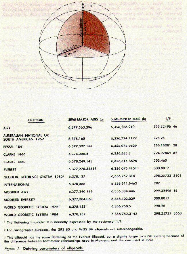
21 Table 1: Geodetic Datums Used in Map Production - End Table 2 (Molodenskiy Transformation Constants to convert from local datum to WGS 84) lists the Delta X, Delta Y, Delta Z, Delta a, and Delta f to transform coordinates from the various datums shown in Appendix D to WGS 84. Values for a and f are listed with figure The direction of the transformation may be reversed by changing the signs of Delta X, Delta Y, Delta Z, Delta a, and Delta f. Note also that R m and R n must be computed with respect to the input ellipsoid Transformation procedures and constants are published in DMA TR , Department of Defense World Geodetic System ELLIPSOIDS Several ellipsoids are presently used in U.S. Military mapping. The goal is to eventually refer all positions to the World Geodetic System (WGS), which has a specific set of defining parameters, or to a WGS compatible ellipsoid. Ellipsoids may be defined by a combination of algebraically related dimensions such as the semi-major and semi- minor axes or the semi-major axis and the flattening. Figure 1 illustrates the defining elements and lists the dimensions of the ellipsoids used by the Defense Mapping Agency Appendix D (index of Preferred Grids, Datums, and Ellipsoids Specified for New Mapping) identifies the extent of currently effective ellipsoids. 2-5 PROJECTIONS The projections used as the framework of all U.S. Military maps and charts have a common characteristic in that they are conformal. Conformality indicates that small areas retain their true shape; angles closely approximate their true values; and, at any point, the scale is the same in all directions Certain projections are prescribed for U.S. Military topographic mapping and charting that shows military grids: Maps at scales of 1:500,000 and larger for areas between 80 south and 84 north, and some hydrographic charts at 1:50,000 and larger, are based on the Transverse Mercator Projection.
22
23
24
25 Maps at 1:1,000,000 scale between 80 south and 84 north, some hydrographic charts, and aeronautical charts at 1:500,000 between 80 south and 80 north, are based on the Lambert Conformal Conic Projection Maps at 1:1,000,000 scale and larger of the polar regions (south of 80 south and north of 84 north), some hydrographic charts smaller than 1:50,000 and at latitude between 70 and the poles, and aeronautical charts at 1:500,000 north of 80 north or south of 80 south, are base, on the Polar Stereographic Projection Coastal charts at 1:75,000 scale and smaller are based on the Mercator Projection General maps at scales smaller than 1:1,000,000 are based on projections individually selected to conform with the intended use of the map. Because of their variety, complexity, and limited use, such projections are not described in this manual Maps produced by coproducing nations in non-u.s. areas of responsibility may be based on other projections such as the Transverse Mercator Projection, the Lambert Conical Orthomorphic Projection (Lambert Conformal Conic Projection), Laborde Projection, New Zealand Map Grid Projection, the Rectified Skew Orthomorphic Projection, etc The following paragraphs contain concepts of some of the prescribed projections; in practice, however, the projections are reduced to a plane surface by use of mathematical formulas. (See Chapter 1 for references to mathematical tables.) Figures 2, 3, 4, 5, and 6 are provided as an aid in the, understanding of these concepts The Mercator Projection is not normally used for military topographic maps; however, it is used extensively for naval ocean navigation and bathymetric charts. Its description also serves as a basis for understanding the Transverse Mercator Projection. The Mercator Projection can be visualized as an ellipsoid projected onto a cylinder with tangency established at the Eqaator and with the polar axis of the ellipsoid in coincidence with the cylinder axis as shown in figure 2. The origins of the projection lines vary and are about three-quarters of the way back along the diameters in the equatorial plane. When the cylinder is opened and flattened, a distortion appears in the polar regions, in as much as the line representing the Equator is the true distance and each parallel is represented by a line as long as the Equator. The poles are infinitely distant from the Equator and can not be shown on the projection. Distortion becomes more pronounced as the distance north and south of the Equator increases. For example, the map scale at 60 north and 60 south is approximately twice that at the Equator A Transverse Mercator Projection is a Mercator Projection where the cylinder has been rotated or transversed 90. The ellipsoid and cylinder are thus tangent along a meridian. By projecting the surface of the ellipsoid onto the cylinder, as shown in figure 3, in the same manner as for the Mercator Projection, the Transverse Mercator Projection is developed on the surface of the cylinder, which is then opened and flattened Distortion - The east and west extremities appear distorted at the outer edges when projected onto a cylinder. The two shaded areas of figure 3 show the varying distortion of two equivalent geographic areas on the some projection. Note that both areas extend 15 in longitude within the 30 to 45 south latitude bond. The area bounded by the 30 and 45 east meridians is greatly magnified in comparison to the area bounded by the 90 and 105 east meridians. When a meridian is tangent to the cylinder of projection, there is no distortion along that meridian. Distances along the tangent meridians are true distances, and all distances within 3 of the meridians are relatively accurate. Therefore, to minimize distortion, the Transverse Mercator Projection, for military purposes, uses 60 longitudinal zones, each zone 6 wide. For example, a zone centered on 3 (central meridian) is bounded by the O and 6 meridians, and a zone centered on 9 is bounded by the 6 and 12 meridians.
26
27
28
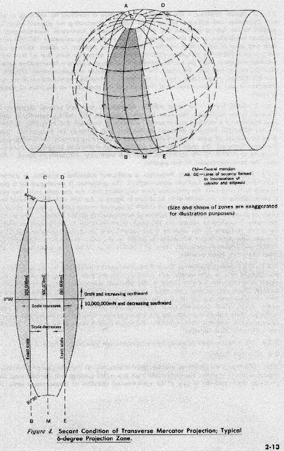
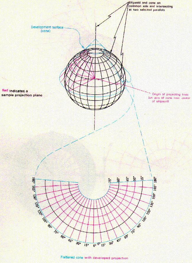
29 Secant condition - The cylinder of projection is modified by reducing its elliptical dimensions and making it secant to the ellipsoid, intersecting the ellipsoid along lines parallel to the central meridian (fig. 4). For the Universal Transverse Mercator grid this condition establishes, in one 6 zone, two lines of secancy approximately 180,000 meters east and west of the central meridian. These lines of seconcy, in effect, allow a more congruous relationship between ellipsoid and map distances than that of the central meridian tangency. Since the central meridian of all zones is given a false easting value of 500,000 meters east (me), the secant lines have coordinates of approximately 320,000 me and 680,000 me respectively. Figure 4 also gives a schematic representation of the scale distortion in any 6 zone. Note that the scale of the projection at the lines of secancy is exact Scale factor - For Most military operations, map and ground distances are assumed to be equivalent. However, in certain geodetic and artillery operations, where long distances are involved and accuracy of results is essential, it is necessary to correct for the difference between distances on the map and distances on the ground. This is done by the use of scale factors from prepared tables or by formula. For the Transverse Mercator Projection, the scale factor is (unity) at the lines of secancy, decreasing inwardly to at the central meridian, and increasing outwardly to about near the zone boundaries at The equator The Polar Stereographic Projection, a conformal azimuthal projection, is similar in both the northern and southern polar regions. The projection is developed on a plane tangent at a pole with the projection lines originating from the opposite pole. The plane is perpendicular to the minor axis, as shown in figure 5. For use with the Universal Polar Stereographic grid, a scale factor of is applied at the origin (pole) to lower the plane of projection to intersect the sphere at approximately 81 07' latitude. This arbitrary geometry is applied to reduce the maximum scale distortion of the tangent projection. As shown in figure 5, the scale is exact (unity scale factor) at approximately 81'07' latitude. The scale factor decreases to at the pole, increases to at 80 00' and attains its maximum value of at 79 30'. The scale factor is constant along any given parallel The Lambert Conformal Conic Projection can be visualized as the projection of the ellipsoid onto a cone whose axis coincides with the polar axis of the ellipsoid as in figure 6. Usually, the cone is secant to the ellipsoid, intersecting along two parallels of latitude. These two parallels are called standard parallels. Meridians appear as straight lines radiating from a point beyond the mapped areas. Parallels appear as arcs of concentric circles which are centered at the point from which the meridians radiate. None of the parallels appear in exactly the projected positions; they are mathematically adjusted to produce the property of conformality. This adjustment is slight if the standard parallels are sufficiently close together The characteristics of prescribed projections are tabulated in table 3.

30 Figure 5. Polar Stereographic Projection
31
32 Figure 6. Lambert Conformal Conic Projection
33 2-6 MILITARY GRIDS Military grids consist of parallel lines intersecting at right angles and forming a regular series of squares. The north-south lines are called eastings and the east-west lines northings. Each grid line is one of an even-interval selection of measurement units. The interval is selected in accordance with the map scale. The unit intervals shown on military map scales are: MAP SCALES UNIT INTERVALS 1:12,500 1,000 1:25,000 1,000 1:50,000 1,000 1:100,000 1,000 or 10,000 1:250,000 10,000 1:500,000 10,000 1:1,000, ,000 with ticks at 10,000 Table 4. Grid Unit Intervals for Various Scale Topographic Maps The grids preferred for military maps are: Universal Transverse Mercator (UTM) grid for areas between 80 south and 84 north Universal Polar Stereographic (UPS) grid for the polar regions south of 80 south and north of 84 north Other grids for certain parts of the world as shown in Appendix D. These grids are being progressively replaced by the UTM grid, with the intent to eventually cover all military mapping of the world with a universal metric grid system Area of application for the various other grids are given in Appendix D. A general description of the grids and numbering systems is given in Chapter 4.
34 2-6.3 Specifications for the Universal Grid Systems follow: Universal Transverse Mercator (UTM) Grid. Projection: Transverse Mercator (Gauss-Kruger type) in zones 6 wide. Ellipsoid: International Bessel 1841 World Geodetic System 1984 Geodetic Reference System (GRS 1980) Longitude of Origin: Central meridian (CM) of each projection zone (3, 9, 15, 21, 27, 33, 39, 45, 51, 57, 63, 69, 75, 81, 87, 93, 99, 105, 111, 117, 123, 129, 135, 141, 147, 153, 159, 165, 171, 177, E and W). Latitude of Origin: O (the Equator). Unit: Meter. False Northing: 0 meters at the Equator for the Northern Hemisphere; 10,000,000 meters at the Equator for the Southern Hemisphere. False Easting: 500,000 meters at the CM of each zone. Scale Factor at the Central Meridian: Grid Zone Designations: See Chapter 3 and Appendix B. Latitude Limits of System: From 80 S to 84 N. Limits of Projection Zones: The zones are bounded by meridians, the longitudes of which are multiples of 6 east and west of the prime meridian. Overlap: On large-scale maps and trig lists, the data for each zone, datum, or ellipsoid overlaps the adjacent zone, datum, or ellipsoid a minimum of 40 kilometers. The UTM grid extends to 80 30'S and 84 30'N, providing a 30-minute overlap with the UPS grid Universal Polar Stereographic (UPS) Grid. Projection: Polar Stereographic. Ellipsoid: World Geodetic System 1984 Longitude of Origin: O and 180 E-W. Latitude of Origin: 90 N and 90 S. Unit: Meter. False Northing: 2,000,000 meters. False Easting: 2,000,000 meters. Scale Factor at the Origin: Grid Zone Designations: See Chapter 3 and Appendix B. Limits of System: North Zone: Polar area north of 84 N. South Zone: Polar area south of 8O S. Overlap: The UPS grid extends to 83 30'N and 79 30'S, providing a 30-minute overlap with the UTM grid Formulas for constructing UTM and UPS grids are contained in DMA TM TRANSFORMING COORDINATES FROM ONE GRID SYSTEM TO ANOTHER GRID SYSTEM. Coordinates may be transformed from one grid system to another grid system, for instance, between a Lambert grid and a UTM grid or between different grid zones. The preferred procedure is to transform the grid coordinates from the first grid system to geographic positions. Then transform the geographic positions to grid coordinates of the second grid system. Note: This procedure does not change the datum. See paragraph 2-3 for the procedure to use when changing from one datum to another datum.
35 CHAPTER 3 THE U.S. MILITARY GRID REFERENCE SYSTEM (MGRS) 3-1 GENERAL DESCRIPTION The U.S. Military Grid Reference System (MGRS) is designed for use with the UTM and UPS grids For convenience, the world is generally divided into 6 by 8 geographic areas, each of which is given a unique identification, called the Grid Zone Designation (fig. 7). These areas are covered by a pattern of 100,000-meter squares. Each square is identified by two letters called tie 100,000-meter square identification. This identification is unique within the area covered by the Grid Zone Designation. Exceptions to this general rule have been made in the post to preserve the 100,000-meter identifications on mapping that already exists. Appendix B shows the method for finding the 100,000-meter square identifications A reference keyed to a gridded map of any scale is made by giving the 100,000- meter square identification together with the numerical location. Numerical references within the 100,000-mater square are given to the desired accuracy in terms of the easting (E) and northing (N) grid coordinates for the point. The Grid Zone Designation usually is prefixed to the identification when references are made in more than one grid zone designation area. 3-2 THE GRID NORTH DESIGNATION An MGRS position location uses the standard military practice of reading "right (easting) and up (northing)". In each portion of a military grid reference (grid zone designation, 100,000-meter square identification, and grid coordinates), the first part provides the easting component and the second part provides the northing component The MGRS is on alphanumeric version of a numerical UTM or UPS grid coordinate For that portion of the world where the UTM grid is specified (80 south to 84 north), the UTM grid zone number is the first element of a Military Grid reference. This number sets the zone longitude limits. Zone 32 has been widened to 9 (at the expense of zone 31) between latitudes 56 and 64 to accommodate southwest Norway. Similarly, between 72 and 84, zones 33 and 35 have been widened to 12 to accommodate Svalbard. To compensate for these 12 wide zones, zones 31 and 37 are widened to 9 and zones 32, 34, and 36 are eliminated The next element is a letter which designates a latitude bond. Beginning at 80 south and proceeding northward, twenty bands are lettered C through X, omitting I and O. The bands are all 8 wide except for bond X which Is 12 wide. Thus, in the UTM portion of the MGRS, the first three characters designate one of the 1197 areas with the dimensions as shown in Table In the Polar regions, there is no zone number. A single letter designates the semicircular area and hemisphere. Since the letters A, B, Y, and Z are used only in the Polar regions, their presence in an MGRS, with the omission of a zone number, designates that the coordinates are UPS.
36 3-2.3 The grid zones are divided into a pattern of 100,000-meter grid squares forming a matrix of rows and columns. Each row and each column is sequentially lettered such that two letters provide, a unique identification, within approximately 9, for each 100,000- meter grid square. Appendix B provides the location and identification of the grid zones and 100,000-meter grid squares. Latitude Longitude Number Table 5. Dimensions of Grid Zone Designation Areas For many years efforts hove been made to reduce the complexity of grid reference systems by standardization to a single world-wide grid reference system. This effort is continuing and will generate additional changes to Appendixes B and D The remainder of this chapter describes the determination of the 100,000-meter square identification, and the military grid reference ,000-METER SQUARE IDENTIFICATION The 100,000-meter columns, including partial columns along zone, datum, and ellipsoid junctions, are lettered alphabetically, A through Z (with I and O omitted), north and south of the Equator, starting at the 180 meridian and proceeding easterly for 18. The alphabetical sequence repeats at 18 intervals To prevent ambiguity of identifications along ellipsoid junctions changes in the order of the row letters are necessary. The row alphabet (second letter) is shifted ten letters. This decreased the maximum distance in which the 100,000-meter square identification is repeated.
37 3-3.3 The 100,000-meter row lettering is based on a 20-letter alphabetical sequence (A through V with I and O omitted). This alphabetical sequence is read from south to north, and repeated at 2,000,000-meter intervals from the Equator The row letters in each odd numbered 6 grid zone are read in an A through V sequence from south to north In each even-numbered 6 grid zone, the some lettering sequence is advanced five letters to F, continued sequentially through V and followed by A through V The advancement or staggering of row letters for the even-numbered zones lengthens the distance between 100,000-meter squares of the same identification Users are cautioned that deviations from the preceding rules were mode in the past. These deviations were an attempt to provide unique grid references within a complicated and disparate world-wide mapping system Determination of 100,000-meter grid square identification is further complicated by the use of different ellipsoids. Figure 8 shows the basic lettering system. Appendix B provides detailed guidance for finding the correct identification in each ellipsoid area.
38
39 3-4 THE MILITARY GRID REFERENCE The MGRS coordinate for a position consists of a group of letters and numbers which include the following elements: The Grid Zone Designation The 100,000-meter square letter identification The grid coordinates (also referred to as rectangular coordinates); the numerical portion of the reference expressed to a desired refinement A reference is written as an entity without spaces, parentheses, dashes, or decimal points. Examples 18S (Locating a point within the Grid Zone Designation) 18SUU (Locating a point within a 100,000-meter square) 18SUU80 (Locating a point within a 10,000-meter square) 18SUU8401 (Locating a point within a 1,000-meter square) 18SUU (Locating a point within a 100-meter square) To satisfy special needs, a reference can be given to a 10-meter square and a 1-meter square as: 18SUU (Locating a point within a 10-meter square) 18SUU (Locating a point within a 1-meter square) 3-5 MGRS APPLICATION All elements of a grid reference need not be used. Their use depends upon the size of the area of Activities, the type of military operations, and the scale of the map to which the reference is keyed. The military area commander usually designates the elements of the grid references to be used. The following paragraphs provide guidance for the use of Grid Zone Designations and 100,000-meter square identifications For military operations spanning large geographical areas, the Grid Zone Designation is usually given (such as IBS). This designation will alleviate ambiguity between identical references that may occur when reporting to a station outside the area. The Grid Zone Designation is always used in giving references on 1:1,000,000 scale and 1:500,000 scale maps For operational areas of lesser extent, but exceeding 100,000 meters, the 100,000-meter square identification is used (such as UU80). The 100,000-meter square identification is uses in reporting references on the 1:250,000 and larger scale maps to avoid ambiguity between identical references which occur every 100,000 motors, and near grid zone junctions and ellipsoid junctions.

40 Figure 9. Method of Reading a U.S. Military Grid Reference from a 1:250,000 Scale Map For small and localized operational areas, the Grid Zone Designations and 100,000-meter square identifications are not used, unless reporting falls within the parameters explained in preceding paragraphs. In the instance of local report only the numerical part of the grid reference is used (such as ). This condition applies to 1:100,000 scale maps and larger Topographic maps at scales 1:500,000 and larger provide a grid reference box with the elements and instructions for making a complete grid reference.
 and up (northing)\" is employed. 3-5.2.")
41 Figure 10. Method of Reading a U.S. Military Grid Reference from a Large Scale Map The numerical part of a grid reference always contains an even number of digits. The first half of the total number of digits represents the easting, and second half the northing. The standard military practice of reading "right (easting) and up (northing)" is employed To read the easting coordinate, locate the first easting (vertical) grid line to the left of the point of reference and read the large digit (or digits), the principal digit labeling the line either in the top or bottom margin or on the line itself. Smaller digits shown as part of a grid number are ignored. Estimate, or scale to the closest tenth of the grid interval, the distance between the easting grid line to the left of the point and the point itself.
42 The reading of the northing coordinate is made in a similar manner. Locate the first northing (horizontal) grid line below the point of reference and read the principal digits labeling the line located in the left or right margin or on the line itself. Then estimate, or scale to the closest tenth of the grid interval, the distance between the northing grid line below the point and the point itself The numerical part of a point reference taken from a 100,000-meter grid (on maps of 1:1,000,000 scale) is a two-digit number; for example: 80. Reading from left to right, the 8 represents the 10,000 digit of the first easting grid line (or grid tick) to the left of the point; the 0 represents the 10,000 digit of the first northing grid line (or grid tick) below the point The numerical part of a point reference taken from a 10,000-meter grid (on maps smaller than 1:100,000 scale and larger than 1:1,000,000 scale) is a four-digit number; for example: Reading from left to right, the 8 represents the 10,000 digit of the first easting grid line to the left of the point, the 4 represents the estimated tenths (nearest 1,000 meters) from the easting grid line to the point, the 0 represents the 10,000 digit of the first northing grid line below the point, and the 1 represents the estimated tenths (nearest 1,000 meters) from the northing grid line to the point. See figure Normally, the numerical part of a point reference taken from a 1,000-meter grid (on maps at scales of 1:100,000 and larger) is a six-digit number; for example: Reading from left to right, the 83 represents the 10,000 and 1,000 digits of the first easting grid line to the left of the point, the 6 represents the estimated or scaled tenths (nearest 100 meters) from the easting line to the point, the 01 represents the 10,000 and 1,000 digits of the first northing grid line below the point, and the 4 represents the estimated or scaled tenths (nearest 100 meters) from the northing grid line to the point. See figure 10.
43 CHAPTER 4 THE NONSTANDARD GRID SYSTEMS IN CURRENT USE CHAPTER 4 THE NONSTANDARD SYSTEMS IN CURRENT USE 4-1 NONSTANDARD GRIDS ON MAPS AND CHARTS Nonstandard Grids There is no regular or uniform global plan for the various grids which make up the nonstandard grid systems. Some were originally developed by the native country and later conveniently adopted by the British and U.S. with or without modifications. Others are of British or French origin. The systems were devised or adopted at different times and, except in certain geographic areas, do not have a direct relationship with one another. Primary considerations in the selection of a grid were the projection, ellipsoid, origin, false coordinates for the origin, and limits which would best suit the particular area. Consequently, various projections and ellipsoids have been employed. Nomenclature, sizes, predominant directions, and outlines of the grids vary considerably. This is demonstrated in Appendix D, which illustrates the layout of the nonstandard grids. This displays what is currently specified for new products and maintenance The nomenclature for the nonstandard grids includes the terms grid, zone, and belt to characterize the systems A grid covers a relatively small area. Its limits consist of combinations of meridians, parallels, loxodomes (rhumb lines), or grid lines. The origin of each grid is arbitrary. It is generally located approximately in the center of the grid and may bear no relation to the origins of other grids or to those of adjacent grids A zone usually is wide in longitude and comparatively narrow in latitude. Its limits, which are regular or in a few cases but irregular in most, consist of parallels and meridians. Each zone has its own origin which, with some few exceptions, falls within the limits of the zone. There is no relation between the origins of the zones, although, in a regional geographic area, those of adjacent zones may be on a common meridian or parallel A belt originally referred to a grid that was extensive in latitude, but narrow in longitude Each grid, zone, and belt has a name. Where groups of adjacent grids or zones cover a regional geographic area, the some name may be used for each; distinction is preserved by adding either a cardinal point or a number and a letter to the name The unit of measure is either meters or yards Normally, a British grid or zone is divided into 500,000-unit squares with each square identified by a letter of the alphabet. In a square composed of twenty-five 500,000- unit squares the letters are arranged alphabetically (the letter I is omitted) in a left to right - top to bottom fashion. Each 500,000-unit is similarly divided into twenty-five 100,000-unit squared, each of which is Identified by a letter following the some plan as for the 500,000-unit squares. The Normal Lettering Plan is illustrated in figure 11. This basic lettering plan is repeated for India Zone IIIA where it exceeds 2,500,000 yards in easting Among the British grids, deviations from the normal lettering system exist for the Irish Transverse Mercator Grid.

44 No letters are used for the Ceylon Belt, New Zealand Map Grid, Nord Algerie Grid, Nord Maroc Grid, Nord Tunisie Grid, Sud Algerie Grid, Sud Maroc Grid, and Sud Tunisie Grid The secondary grids are constantly changing. Specifications for those grids currently in this category are given in table 6.
Georeferencing, Map Projections, Cartographic Concepts. -Coordinate Systems -Datum
 Georeferencing, Map Projections, Cartographic Concepts -Map Projections -Coordinate Systems -Datum Map projection is "the process of systematically transforming positions on the Earth's spherical surface
Downloaded from MILITARY STANDARD DEPARTMENT OF DEFENSE WORLD GEODETIC SYSTEM (WGS)
") METRIC 11 JANUARY 1994 MILITARY STANDARD DEPARTMENT OF DEFENSE WORLD GEODETIC SYSTEM (WGS) AMSC N/A AREA MCGT DISTRIBUTION STATEMENT A. Approved for public release; distribution is unlimited. FOREWORD
METRIC 11 JANUARY 1994 MILITARY STANDARD DEPARTMENT OF DEFENSE WORLD GEODETIC SYSTEM (WGS) AMSC N/A AREA MCGT DISTRIBUTION STATEMENT A. Approved for public release; distribution is unlimited. FOREWORD
Geographic coordinate systems
 1 Geographic coordinate systems In this chapter you ll learn about longitude and latitude. You ll also learn about the parts that comprise a geographic coordinate system including Spheres and spheroids
MILITARY SPECIFICATION DIGITAL LANDMASS BLANKING (DLMB) DATA PROGRAM
 DATA PROGRAM") METRIC MIL-D-89021 15 June 1991 SUPERSEDING PS/1CJ/010 September 1983 MILITARY SPECIFICATION DIGITAL LANDMASS BLANKING (DLMB) DATA PROGRAM This specification is approved for use by all Departments and
METRIC MIL-D-89021 15 June 1991 SUPERSEDING PS/1CJ/010 September 1983 MILITARY SPECIFICATION DIGITAL LANDMASS BLANKING (DLMB) DATA PROGRAM This specification is approved for use by all Departments and
Map projections. Rüdiger Gens
 Rüdiger Gens Coordinate systems Geographic coordinates f a: semi-major axis b: semi-minor axis Geographic latitude b Geodetic latitude a f: flattening = (a-b)/a Expresses as a fraction 1/f = about 300
Shape e o f f the e Earth
 1 Coordinate Systems & Projections Coordinate Systems Two map layers are not going to register spatially unless they are based on the same coordinate system. 2 Contents Shape of the earth Datum Projections
This week s topics. Week 6. FE 257. GIS and Forest Engineering Applications. Week 6
 FE 257. GIS and Forest Engineering Applications Week 6 Week 6 Last week Chapter 8 Combining and splitting landscape features and merging GIS databases Chapter 11 Overlay processes Questions? Next week
CHAIRMAN OF THE JOINT CHIEFS OF STAFF INSTRUCTION
 CHAIRMAN OF THE JOINT CHIEFS OF STAFF INSTRUCTION J-3 CJCSI 3900.01C DISTRIBUTION: A, B, C, J POSITION (POINT AND AREA) REFERENCE PROCEDURES Reference: DODD 5105.60, 11 October 1996, National Imagery and
Outline. Shape of the Earth. Geographic Coordinates (φ, λ, z) Ellipsoid or Spheroid Rotate an ellipse around an axis. Ellipse.
 Ellipsoid or Spheroid Rotate an ellipse around an axis. Ellipse.") Map Projections Outline Geodesy and map projections Prof. D. Nagesh Kumar Department of Civil Engineering Indian Institute of Science Bangalore 560 012, India http://www.civil.iisc.ernet.in/~nagesh Shape
Map Projections Outline Geodesy and map projections Prof. D. Nagesh Kumar Department of Civil Engineering Indian Institute of Science Bangalore 560 012, India http://www.civil.iisc.ernet.in/~nagesh Shape
WHERE ARE YOU? Maps & Geospatial Concepts Fall 2015
 WHERE ARE YOU? Maps & Geospatial Concepts Fall 2015 Where are you? Relative location I m at school Absolute Location 45 26 18.07 122 43 50.78 Where is Boston? Introducing Geodesy, Ellipsoids & Geoids Geodesy
FM Map Reading and Land Navigation
 FM 3-25.26 Map Reading and Land Navigation CHAPTER 4 GRIDS This chapter covers how to determine and report positions on the ground in terms of their locations on a map. Knowing where you are (position
WHERE ARE YOU? Maps & Geospatial Concepts Fall 2012
 WHERE ARE YOU? Maps & Geospatial Concepts Fall 2012 Where are you? Relative location I m at school Absolute Location 45 26 18.07 122 43 50.78 Datums Datums A reference surface of the Earth Used as the
What is a Map Projection?
 What is a Map Projection? It is how we represent a three dimensional Earth on a flat piece of paper However The process of transferring information from the Earth to a map causes every projection to distort
ch02.pdf chap2.pdf chap02.pdf
 Introduction to Geographic Information Systems 8th Edition Karl Solutions Manual Full Download: http://testbanklive.com/download/introduction-to-geographic-information-systems-8th-edition-karl-solutions-manu
Georeferencing. Place names Postal addresses Postal codes Coordinate systems (lat/long, UTM, etc.)
") Georeferencing Georeferencing Used to describe the act of assigning locations to data or information Certain requirements include that they are: unique, have shared meaning, and are persistent through
Georeferencing Georeferencing Used to describe the act of assigning locations to data or information Certain requirements include that they are: unique, have shared meaning, and are persistent through
EnvSci360 Computer and Analytical Cartography
 EnvSci360 Computer and Analytical Cartography Lecture 3 Geodesy Map Projections, Datums, and Coordinate Systems 1 Geodesy The science of measuring and representing the shape and size of the earth, and
Map projections. Rüdiger Gens
 Rüdiger Gens 2 Outline! Relevant terms! Why map projections?! Map projection categories " Projection surfaces " Features preserved from distortions! Map projection examples! Right choice Relevant terms!
NR402 GIS Applications in Natural Resources Lesson 4 Map Projections
 NR402 GIS Applications in Natural Resources Lesson 4 Map Projections From http://www.or.blm.gov/gis/ 1 Geographic coordinates Coordinates are expressed as Latitude and Longitude in Degrees, Minutes, Seconds
Map Projections. What does the world look like? AITOFF AZIMUTHAL EQUIDISTANT BEHRMANN EQUAL AREA CYLINDRICAL
 Map Projections What does the world look like? AITOFF AZIMUTHAL EQUIDISTANT BEHRMANN EQUAL AREA CYLINDRICAL 1 CYLINDRICAL EQUAL AREA BONNE CRASTER PARABOLIC 2 ECKERT I ECKERT III ECKERT V There are many
Lecture 4. Coordinate Systems & Projections
 Lecture 4 Coordinate Systems & Projections Outline Geodesy Geoids Ellipsoids Geographic Coordinate Systems Magnetic North vs. True North Datums Projections Applying Coordinate Systems and Projections Why
Lesson 5: Map Scale and Projections
 Organizing Data and Information Lesson 5: Map Scale and Projections Map Scales Projections Information can be organized as lists, numbers, tables, text, pictures, maps, or indexes. Clusters of information
Map Projections. Chapter 4 MAP PROJECTION
 Map Projections Chapter 4 Map Projections What is map projection? Why are map projections drawn? What are the different types of projections? Which projection is most suitably used for which area? In this
Military Map Reading 201
 Military Map Reading 201 This information paper is designed to resolve the confusion between the Universal Transverse Mercator (UTM) and the Military Grid Reference System (MGRS) coordinates. The two systems
Importance of Understanding Coordinate Systems and Map Projections.
 Importance of Understanding Coordinate Systems and Map Projections. 1 It is extremely important that you gain an understanding of coordinate systems and map projections. GIS works with spatial data, and,
Map Projections & Coordinate Systems
 Map Projections & Coordinate Systems 9/7/2017 1 Why? Laying the Earth Flat Need convenient means of measuring and comparing distances, directions, areas, shapes. Traditional surveying instruments measure
A PRIMER ON COORDINATE SYSTEMS Commonly Used in Michigan
 A PRIMER ON COORDINATE SYSTEMS Commonly Used in Michigan David P. Lusch, Ph.D., GISP Department of Geography Remote Sensing & GIS Research and Outreach Services Group Michigan State University September,
Dr. ABOLGHASEM AKBARI Faculty of Civil Engineering & Earth Resources, University Malaysia Pahang (UMP)
") Workshop on : Dr. ABOLGHASEM AKBARI Faculty of Civil Engineering & Earth Resources, University Malaysia Pahang (UMP) 14-15 April 2016 Venue: Tehran, Iran GIS definitions GIS: A simplified view of the real
Workshop on : Dr. ABOLGHASEM AKBARI Faculty of Civil Engineering & Earth Resources, University Malaysia Pahang (UMP) 14-15 April 2016 Venue: Tehran, Iran GIS definitions GIS: A simplified view of the real
Coordinate Systems. Location on earth is defined by coordinates
 Coordinate Systems We think of the earth as a sphere It is actually a spheroid (ellipsoid), slightly larger in radius at the equator than at the poles Shape of the Earth Location on earth is defined by
GIST 3300 / Geographic Information Systems. Last Time. Today
 GIST 3300 / 5300 Last Time Ellipsoids and Datums Today Map Projections Map Projections Today we will build on the concepts of Geographic Coordinate Systems, Ellipsoids and Datums and add the concepts of
Georeferencing. datum. projection. scale. The next few lectures will introduce you to these elements. on the Earth, you ll need to understand how
 Georeferencing GOAL: To assign a location to all the features represented in our geographic information data In order to do so, we need to make use of the following elements: ellipsoid/geoid To determine
Intro to GIS Fall 2010 Georeferencing & Map Projections
 Intro to GIS Fall 2010 Georeferencing & Map Projections SHAPE OF THE EARTH Earth's Shape Geoid: shape of earth minus topographic features (irregular due to local variations in gravity) Ellipsoid: elongated
Map Projections 2/4/2013. Map Projections. Rhumb Line (Loxodrome) Great Circle. The GLOBE. Line of constant bearing (e.g., 292.
 Great Circle. The GLOBE. Line of constant bearing (e.g., 292.") The GLOBE ADVANTAGES Directions True Distances True Shapes True Area True DISADVANTAGES Very small scale with little detail. Costly to reproduce and update. Difficult to carry around. Bulky to store. FACTS
The GLOBE ADVANTAGES Directions True Distances True Shapes True Area True DISADVANTAGES Very small scale with little detail. Costly to reproduce and update. Difficult to carry around. Bulky to store. FACTS
The Elements of GIS. Organizing Data and Information. The GIS Database. MAP and ATRIBUTE INFORMATION
 GIS s Roots in Cartography Getting Started With GIS Chapter 2 Dursun Z. Seker MAP and ATRIBUTE INFORMATION Data (numbers and text) store as files refer to them collectively as a database gather inform.
Control Surveys and Coordinate Systems
 Control Surveys and Coordinate Systems The Earth is Round Basic Shape of the Earth: Oblate Spheroid of Revolution The length of the equatorial axis is approximately 27 miles greater than the polar axis.
Introduction to Cartography GEOG 2016 E. Lecture-2 Geodesy and Projections
 Introduction to Cartography GEOG 2016 E Lecture-2 Geodesy and Projections What is Geodesy? The science of geodesy determines: Earth s shape and Interrelation of different points on earth s surface The
Understanding Projections for GIS
 Presented by John Schaeffer Juniper GIS Services, Inc. This PowerPoint is available at JuniperGIS.com Presentation Objectives To understand basic concepts on projections and coordinate systems for the
Working with georeferenced data. What is georeferencing? Coordinate Systems. Geographic and Projected Coordinate System
 GIS501 Fundamentals of Geographical Information Systems (GIS) Coordinate Systems Working with georeferenced data What is georeferencing? Geographically referenced data which is, in some way, referenced
Chapter 3 Models of the Earth. 3.1 Finding Locations on the Earth. 3.1 Objectives
 Chapter 3 Models of the Earth 3.1 Finding Locations on the Earth 3.1 Objectives Explain latitude and longitude. How can latitude and longitude be used to find locations on Earth? How can a magnetic compass
Map Projections. Displaying the earth on 2 dimensional maps
 Map Projections Displaying the earth on 2 dimensional maps Map projections Define the spatial relationship between locations on earth and their relative locations on a flat map Are mathematical expressions
Introduction to Geographic Information Science. Updates/News. Last Lecture. Geography 4103 / Map Projections and Coordinate Systems
 Geography 4103 / 5103 Introduction to Geographic Information Science Map Projections and Coordinate Systems Updates/News Thursday s lecture Reading discussion 1 find the readings online open questions,
Geographers Perspectives on the World
 What is Geography? Geography is not just about city and country names Geography is not just about population and growth Geography is not just about rivers and mountains Geography is a broad field that
EN5302. US ARMY ENGINEER SCHOOL CARTOGRAPHY II Grid Construction, Plotting and Projection Graticules
 SUBCOURSE EN5302 EDITION 6 US ARMY ENGINEER SCHOOL CARTOGRAPHY II Grid Construction, Plotting and Projection Graticules TABLE OF CONTENTS PAGE INTRODUCTION... iii GRADING AND CERTIFICATION INSTRUCTIONS...
1. Geospatial technology rarely links geospatial data to nonspatial data. a. True *b. False
 Chapter 2 Where in the Geospatial World Are You? 1. Geospatial technology rarely links geospatial data to nonspatial data. 2. For geospatial technology to work, every location on Earth must be: a. inhabited
What is Geodesy? Types of Geodesy terrestrial or classical geodesy space geodesy theoretical geodesy
 What is Geodesy? Geodesy is the study of: The size, shape and motion of the earth The measurement of the position and motion of points on the earth's surface, and The study of the earth's gravity field
NAVIGATION THEORY QUESTIONS Basics of Navigation
 NAVIGATION THEORY QUESTIONS Basics of Navigation Q610065 look at it The angle between the plane of the ecliptic and the plane of equator is approx? 23.5 degrees In which two months of the year is the difference
Applied Cartography and Introduction to GIS GEOG 2017 EL. Lecture-1 Chapters 1 and 2
 Applied Cartography and Introduction to GIS GEOG 2017 EL Lecture-1 Chapters 1 and 2 What is GIS? A Geographic Information System (GIS) is a computer system for capturing, storing, querying, analyzing and
Lecture 10-14: Map Projections and Coordinate System
 URP 1281 Surveying and Cartography Lecture 10-14: Map Projections and Coordinate System December 27, 2015 Course Teacher: Md. Esraz-Ul-Zannat Assistant Professor Department of Urban and Regional Planning
Welcome to Lesson 4. It is important for a GIS analyst to have a thorough understanding of map projections and coordinate systems.
 Welcome to Lesson 4. It is important for a GIS analyst to have a thorough understanding of map projections and coordinate systems. A GIS without coordinates would simply be a database like Microsoft Excel
Plane coordinates ~~~~~~~~~~
 Coordinate Systems & Map Projections Geographic coordinates A Basic Introduction to Coordinate Systems & Map Projections Latitude & longitude Angles Parallels & meridians Lines Plane coordinates ~~~~~~~~~~
Chapter 3 Geographic Location Systems
 Chapter 3 Geographic Location Systems In this chapter you will learn about: Latitude and longitude Universal Transverse Mercator (UTM) U.S. Public Land Survey Other geographic location systems Geographic
Notes on Projections Part II - Common Projections James R. Clynch February 2006
 Notes on Projections Part II - Common Projections James R. Clynch February 2006 I. Common Projections There are several areas where maps are commonly used and a few projections dominate these fields. An
DRAFT MARINE ARTILLERY SURVEY
 MARINE ARTILLERY SURVEY Table of Contents Chapter 1: Mission, Organization, and Duties Section I: Mission PARA TITLE PAGE 1-1 Common Grid 1-1 1-2 Components of a Common Grid 1-1 1-3 Fundamentals of Survey
Projections & GIS Data Collection: An Overview
 Projections & GIS Data Collection: An Overview Projections Primary data capture Secondary data capture Data transfer Capturing attribute data Managing a data capture project Geodesy Basics for Geospatial
THE EVOLUTION OF MATHEMATICAL BASES OF POLISH TOPOGRAPHIC MAPS DURING THE RECENT 80 YEARS
 Michal Stankiewicz is a lecturer in map redaction, topography and topographic cartography in Department of Geodesy and Cartography, Warsaw University of Technology. In 1979 he obtained the degree of Doctor
Geo Referencing & Map projections CGI-GIRS 0910
 Geo Referencing & Map projections CGI-GIRS 0910 Where are you? 31UFT8361 174,7 441,2 51 58' NB 5 40' OL 2/60 Who are they? 3/60 Do geo data describe Earth s phenomena perfectly? Georeference systems ellipsoid
SECTION 4 PARCEL IDENTIFIERS 4.1 LONGITUDE AND LATITUDE
 SECTION 4 PARCEL IDENTIFIERS 4.1 LONGITUDE AND LATITUDE Most maps must be drawn in such a way that points and areas can be located accurately on the earth's surface and described objectively. A uniform
1/28/16. EGM101 Skills Toolbox. Oblate spheroid. The shape of the earth Co-ordinate systems Map projections. Geoid
 EGM101 Skills Toolbox Oblate spheroid The shape of the earth Co-ordinate systems Map projections The geoid is the shape that the surface of the oceans would take under the influence of Earth's gravitation
REFERENCING COORDINATE SYSTEMS MAP PROJECTIONS GEOREFERENCING
 GIS in Ecology SPATIAL REFERENCING COORDINATE SYSTEMS MAP PROJECTIONS GEOREFERENCING : :1 Where on earth? Early mapmakers recognized the need for a system that could locate features on the earth's surface.
Lecture 2. Map Projections and GIS Coordinate Systems. Tomislav Sapic GIS Technologist Faculty of Natural Resources Management Lakehead University
 Lecture 2 Map Projections and GIS Coordinate Systems Tomislav Sapic GIS Technologist Faculty of Natural Resources Management Lakehead University Map Projections Map projections are mathematical formulas
Geo Referencing & Map projections CGI-GIRS 0910
 Geo Referencing & Map projections CGI-GIRS 0910 Where are you? 31UFT8361 174,7 441,2 51 58' NB 5 40' OL 2/60 Who are they? 3/60 Do geo data describe Earth s phenomena perfectly? Georeference systems ellipsoid
Data acquisition and integration 1.
 Data acquisition and integration 1. Ferenc Végső Data acquisition and integration 1.: Ferenc Végső Lector: Árpád Barsi This module was created within TÁMOP - 4.1.2-08/1/A-2009-0027 "Tananyagfejlesztéssel
GEOMATICS ENGINEERING / SURVEYING
 1 GEOMATICS ENGINEERING / SURVEYING CHAPTER 1 Dr. Muhammad Ashraf Javid Assistant Professor Department of Civil and Environmental Engineering Email: muhammad.javid@unizwa.edu.om 2 Geomatics Engineering
GEOGRAPHIC COORDINATE SYSTEMS
 GEOGRAPHIC COORDINATE SYSTEMS Introduction to GIS Winter 2015 What is Georeferencing? Used to establish a location on the Earth s surface 1 st order polynomial transformation Georeferencing toolbar What
Projections Part I - Categories and Properties James R. Clynch February 2006
 I. Introduction and References Projections Part I - Categories and Properties James R. Clynch February 2006 The world is, approximately, a sphere. Maps are flat. Making maps requires some method of putting
12/26/2012. Geographic Information Systems * * * * GIS (... yrezaei
 ( - Geographic Information Systems ( ( 1 2 3 Information System Data base DB IS IS DB (Knowledge ( ( (System (Information System - (Georefrence Analysis Data + Knowledge ======== Information 4 5 ( < 10%
Overview key concepts and terms (based on the textbook Chang 2006 and the practical manual)
") Introduction Geo-information Science (GRS-10306) Overview key concepts and terms (based on the textbook 2006 and the practical manual) Introduction Chapter 1 Geographic information system (GIS) Geographically
Introduction Geo-information Science (GRS-10306) Overview key concepts and terms (based on the textbook 2006 and the practical manual) Introduction Chapter 1 Geographic information system (GIS) Geographically
Navigation. Longitude and Latitude Foundations of Navigation. MTPs:
 Navigation 3.01 Foundations of Navigation References: FTGU pages 177-178, 184-190 Transport Canada Study and Reference Guide Glider Pilot Canada Flight Training Manual Pilot Navigation http://en.wikipedia.org/wiki/transverse_mercator_projection#spherical_transverse_mercator
2. Which geometric model has been used at some time to describe the earth? a. Sphere b. Oblate ellipsoid c. Flat disk. d. Geoid e.
 01 02 03 04 05 06 07 08 09 10 11 12 13 14 15 16 17 18 19 20 21 22 23 24 25 26 27 28 29 30 31 32 33 34 35 36 37 38 39 40 41 42 43 44 45 46 47 48 49 50 Geography 12 Sample Mid-Term Examination Before you
A map is a small-scale flat-surface representation of some portion of the earth s surface.
 MAPS AND CHARTS A map is a small-scale flat-surface representation of some portion of the earth s surface. A representation that is designed for plotting navigational information is called a chart. Often
4 Survey Datums. 4.1 Horizontal Datum Policy SURVEY DATUMS SEPTEMBER 2006
 4 Survey Datums Today s multi-organizational Project Development efforts require the use of common, accurate horizontal and vertical survey datums and consistent, precise control-survey procedures to ensure
Fundamentals of Surveying (LE/ESSE )
") Fundamentals of Surveying (LE/ESSE 2620 3.0) Lecture 2 Basics of Surveying Dr.-Ing. Jian-Guo Wang Geomatics Engineering York University Fall 2017 1 2-1. Overview Part 1: Basics - The Earth s Shape & Size.
Fundamentals of Surveying (LE/ESSE 2620 3.0) Lecture 2 Basics of Surveying Dr.-Ing. Jian-Guo Wang Geomatics Engineering York University Fall 2017 1 2-1. Overview Part 1: Basics - The Earth s Shape & Size.
Projections and Coordinate Systems
 Projections and Coordinate Systems Overview Projections Examples of different projections Coordinate systems Datums Projections Overview Projections and Coordinate Systems GIS must accurately represent
Map Projections & Coordinate Systems 9/10/2013. Why? M. Helper GEO327G/386G, UT Austin 2. M. Helper GEO327G/386G, UT Austin 4
 Map Projections & Coordinates Laing the earth flat Wh? Need convenient means of measuring and comparing distances, directions, areas, shapes. Traditional surveing instruments measure in meters or feet,
Choosing a Suitable Projection for Navigation in the Arctic
 Choosing a Suitable Projection for Navigation in the Arctic Dr. Andriani Skopeliti, Prof. Lysandros Tsoulos Cartography Laboratory, School of Rural and Surveying Engineering, National Technical University
LAND NAVIGATION 2-1. DEFINITION
 LAND NAVIGATION MAPS Cartography is the art and science of expressing the known physical features of the earth graphically by maps and charts. No one knows who drew, molded, laced together, or scratched
Data acquisition and integration 1.
 University of West Hungary, Faculty of Geoinformatics Ferenc Végső Data acquisition and integration 1. module DAI1 The basics of positioning SZÉKESFEHÉRVÁR 2010 The right to this intellectual property
Map Projections & Coordinate Systems 9/7/2017
 Map Projections & Coordinate Sstems Laing the Earth Flat Wh? Need convenient means of measuring and comparing distances, directions, areas, shapes. Traditional surveing instruments measure in meters or
Spatial Reference Systems. Introduction
 Spatial Reference Systems Wolfgang Kainz Professor of Cartography and Geoinformation Department of Geography and Regional Research University of Vienna wolfgang.kainz@univie.ac.at Introduction Historic
ROYAL CANADIAN AIR CADETS PROFICIENCY LEVEL FOUR INSTRUCTIONAL GUIDE SECTION 4 EO C USE A VISUAL FLIGHT RULES (VFR) NAVIGATION CHART (VNC)
 NAVIGATION CHART (VNC)") ROYAL CANADIAN AIR CADETS PROFICIENCY LEVEL FOUR INSTRUCTIONAL GUIDE SECTION 4 EO C437.02 USE A VISUAL FLIGHT RULES (VFR) NAVIGATION CHART (VNC) Total Time: 60 min PREPARATION PRE-LESSON INSTRUCTIONS Resources
ROYAL CANADIAN AIR CADETS PROFICIENCY LEVEL FOUR INSTRUCTIONAL GUIDE SECTION 4 EO C437.02 USE A VISUAL FLIGHT RULES (VFR) NAVIGATION CHART (VNC) Total Time: 60 min PREPARATION PRE-LESSON INSTRUCTIONS Resources
2. GETTING STARTED WITH GIS
 2. GETTING STARTED WITH GIS What are geographic information systems and what are they used for? ArcGIS: ArcMap, ArcCatalog and ArcToolbox Vector data vs. raster data vs. attribute tables Polygons, polylines,
The Wildlife Society Meet and Greet. Come learn about what the UNBC Student Chapter of TWS is all about!
 Georeferencing I GEOG 300, Lecture 4 Dr. Anthony Jjumba 1 The Wildlife Society Meet and Greet Quiz Come learn about what the UNBC Student Chapter of TWS is all about! 5:30 7:30 PM, Wednesday September
The Gauss Conform Coordinate
 Surveying The South African Coordinate Reference System (Part 2) by Aslam Parker, Chief Directorate: National Geo-spatial Information Part 1 of this article (see PositionIT Nov/Dec 2011) focused on the
DIPA Flowchart All you need to know
 DIPA Flowchart All you need to know 0. Overview of Remote Sensing 1. Radiometric correction (Step 1,2,3) System radiometric correction Atmospheric correction Bidirectional correction 2. Geometric registration
Recall: The scale transformation
 Recall: The scale transformation Geography 12: Maps and Spatial Reasoning Lecture 3: Map Projection Basics Professor Keith Clarke 1:400M The real world A representation of the world A cartographic problem
The Earth is a Rotating Sphere
 The Earth is a Rotating Sphere The Shape of the Earth Earth s Rotation ( and relative movement of the Sun and Moon) The Geographic Grid Map Projections Global Time The Earth s Revolution around the Sun
Lab #3 Map Projections.
 Lab #3 Map Projections http://visual.merriam-webster.com/images/earth/geography/cartography/map-projections.jpg Map Projections Projection: a systematic arrangement of parallels and meridians on a plane
Boolean Operators and Topological OVERLAY FUNCTIONS IN GIS
 Boolean Operators and Topological OVERLAY FUNCTIONS IN GIS Query asking a question of the attribute data Standard Query Language (SQL) is used to query the data There are 4 basic statements used to get
Map Projections & Coordinate Systems 1/25/2018
 Map Projections & Coordinate Sstems Laing the Earth Flat How? Projections transformation of curved earth to a flat map; sstematic rendering of the lat. & lon. graticule to rectangular coordinate sstem.
Georeferencing. Where on earth are we? Critical for importing and combining layers for mapping
 Georeferencing Where on earth are we? Critical for importing and combining layers for mapping 1. The Geoid Earth is not a perfect sphere, it is ellipsoidal.. earth is the 'Geoid'. The difference between
Susan Cutter et al. Aug, 2002, The Professional Geographer, 54(3): David Tenenbaum GEOG 070 UNC-CH Spring 2005
: David Tenenbaum GEOG 070 UNC-CH Spring 2005") What is Geography? Geography is not just about city and country names Geography is not just about population and growth Geography is not just about rivers and mountains Geography is a broad field that
What is Geography? Geography is not just about city and country names Geography is not just about population and growth Geography is not just about rivers and mountains Geography is a broad field that
Mapping coordinate systems
 Mapping coordinate systems 1. The Earth's Graticule Latitude and Longitude The graticule is the imaginary grid of lines running east-west (lines of latitude = parallels) and north-south lines of longitude
Modern Navigation. Thomas Herring
 12.215 Modern Navigation Thomas Herring Today s class Map Projections: Why projections are needed Types of map projections Classification by type of projection Classification by characteristics of projection
Geodetics: Implications for GIS Professionals May 10, 2018
 Experts in Geomatics, Surveying, Positioning, Geospatial Data, and Mapping Sciences Geodetics: Implications for GIS Professionals May 10, 2018 Michael Barnes APSG Education Foundation Chair 2010-2020 APSG
Dirty REMOTE SENSING : Lecture 8 A mapping interlude..
 Dirty REMOTE SENSING : Lecture 8 A mapping interlude.. Stuart Green Teagasc Spatial Analysis Group Stuart.green@teagasc.ie Web for the Week: http://electronics.howstuffworks.com/gps.htm http://www.cstars.ucdavis.edu/classes/ers186-w03/lecture17/lecture17.ppt
Modern Navigation. Thomas Herring
 12.215 Modern Navigation Thomas Herring Today s Class Latitude and Longitude Simple spherical definitions Geodetic definition: For an ellipsoid Astronomical definition: Based on direction of gravity Relationships
Analytical and Computer Cartography Lecture 3: Review: Coordinate Systems
 Analytical and Computer Cartography Lecture 3: Review: Coordinate Systems Geographic Coordinates NAD83 NAD27 remained in use until the earthcentered international GRS80 was complete (Geodetic Reference
P R O J E C T I O N S. Map Projections. Introduction to. Map Projections. with. TNTmips. TNTedit TNTview. page 1
 P R O J E C T I O N S Introduction to Map Projections Map Projections with TNTmips page 1 TNTedit TNTview Before Getting Started Positions in a georeferenced spatial object must refer to a particular coordinate
How does an ellipsoid differ from a sphere in approximating the shape and size of the Earth?
 Chapter 02 Test Bank Worksheet Questions 1. What is a map projection? Topic: Map Projection 2. How does an ellipsoid differ from a sphere in approximating the shape and size of the Earth? Topic: Ellipsoid
The Nature of Spatial Data. Keith C. Clarke Geography UCSB
 The Nature of Spatial Data Keith C. Clarke Geography UCSB Geographic primitives G = g (x, y, z, s, A, t) [x, y, z] = f(λ, φ, d) Geography also highly dependent upon model First, the datum (d) Models of
B. Topographic maps are also called. contour maps
 Topographic Maps Introduction A. Topographic maps are essential tools in geologic and engineering studies because they show the configuration of Earth's surface in remarkable detail and permit one to measure