What s s in YOUR toolkit?
|
|
|
- Bryan Baldwin
- 5 years ago
- Views:
Transcription


1 New Microscopies for Polymer Analyses What s s in YOUR toolkit? Barbara Foster Microscopy/Marketing & Education bfoster@mme1.com
2 *IDKYCDT! Light/Confocal +(Chemical Fingerprints) FT-IR Raman AFM +++ In Liquids (including electrochemistry) Thermal Analysis Ultramicrotomy With NSOM, Raman confocal and fluorescence spectroscopy *I didn t know you could do that!

3 FT-IR + Microscopy Light from the microscope impinges on the surface and undergoes total internal reflection In the process of reflecting, the beam generates a small, evanescent field at the interface, which penetrates the second material. If the second material absorbs this e n e r g y, the intensity for the reflected beam is reduced or attenuated. This absorption is selective, dependent on the chemistry of the second material. Scanning the attenuation over a specific wavelength region ( ,250 nm or 4000 to 650cm-1) produces a spectrum that provides a specific molecular fingerprint for the second material. Smiths Detection
4 Target Measure Locate glass particle in oil (No contact) Spectrum of oil Mixed spectrum oil + glass Pure spectrum, glass

5 Raman Confocal Like FT-IR: another Vibrational Spectroscopy Inelastic scattering Compliments FT-IR FT-IR does not work well with materials exhibiting strong O-H H or N-H N H effects; Raman does The Challenges: Very weak signal! (10-4 of fluorescence; 10-7 or 10-8 of ambient) Often in same spectral range as fluorescence


6 Raman + Renishaw Horiba/JY
 cast on vanadium oxide ceramic Mobile cation: Li+ Anion:")
7 Ion diffusion across a polymer membrane Triflate in water (anion) Trifluoromethane sulfonate Note peaks at 766 nm and 1034 nm for un-coordinated anion Li+ triflate complex at varying depths > d Li+ doped p(eto) cast on vanadium oxide ceramic Mobile cation: Li+ Anion: Triflate Horiba/JY
8 Scanning Probe Microscopy (SPM) Atomic Force Microscopy (AFM) Scanning Tunneling Microscopy (STM)


9 What do YOU need to do? STM 300 C Lithography Resistance Near Field Vacuum Nanotechnology Education Adhesion Roughness Conductivity Shear Force Magnetism Elasticity Liquid Biology Nanotubes Polymers Raman
10 How does AFM work? Photodiode Feedback loop Laser Piezo Tip Image Sample


11 Multiple configurations


12 Critical Atomic Resolution 12x12 nm STM image of carbon nanotube deposited on HOPG substrate. Atomic structure of nanotube is clearly visible. Image courtesy of Prof. V.K. Nevolin, Moscow Institute of Electronic Engineering.


13 AFM Topography & Phase images Polyethylene Topography Phase Scan size: 4x4μm


14 AFM Topography & Phase images Polyethylene oxide Topography Phase Scan size: 25x25 µm

15 Electromotive Force Microscopy (EFM) Polymer blend: app-ma Polymer blend (app-ma) with two different dielectric constants Scan size: 1.5 x 1.5 μm A.V. Krayev et al. Polymer 45 (2004)
 Topography Potential")

16 Surface potential distribution Scanning Kelvin Mode (SKM) Topography Potential (2-pass, semi-contact) Azobenzene derivative - self-assembled film Scan size: 45x45 µm
 Topography AFAM")

17 Atomic Force Acoustical Microscopy Polyethylene strips (HD/LD) Topography AFAM AFAM senses local surface elasticity with high lateral resolution + Quantitation Scan size: 10x10 μm

 Scan Size:")
18 AFAM Spherulite, branched-chain chain polyethylene Topography AFAM (Highlights growth in radial direction) Scan Size: 12x12 μm


19 Nanolithography & manipulation Nanolithography (mechanical or oxidative)

20 Nanomanipulation Manipulation of the Nanotubes by Lithography Illustrating movement in a specified direction MIEE, Institute of Fullerene & Nanomaterials of RAS, Russia


21 External Magnetic Field - setup


22 Demagnetization of hard disk (MFM/external) a) H=0Oe b) H=1050Oe c) H=1280Oe d) H=1380Oe e) H=1460Oe f) H=1520Oe

23 High Throughput AFM (HTCM) AFM + RL stage Automation software Applications Polymer batch studies* Biotech


24 Optimization Synthesis Property Characterization Database/Libraries Data Processing


25

26 Atomic Force Microscopy. Influence of Processing Conditions for Polyethylene Compositions. Structural Dispersion Parameters and Mechanical Properties. NT-LAB, KAZAN GROUP.

27 Carbon black particle distribution within LDPE, Banbury batch mixer 004 Particle vol. fraction AFM, Topography Scan size: 7x7 µm Carbon particles size, nm *Dutch Polymer Institute, TUE, Eindhoven, The Netherlands
28 Carbon black particles distribution within LDPE, Tyson mixer (7-section screw ) 0,003 Объемная Particle vol. доля fraction частиц 0,002 0,001 0, AFM/Topography Scan size: 4x4 µm Carbon particles size, nm *Dutch Polymer Institute, TUE, Eindhoven, The Netherlands
29 Carbon black particles distribution within HDPE, Tyson mixer (7-section screw. 04 Particle vol. fraction AFM/Topography Scan size: 7x7 µm Carbon particles size, nm *Dutch Polymer Institute, TUE, Eindhoven, The Netherlands
30 High Throughput Applications MORPHOLOGY Structure determines function Morphology is a clue to internal chemical structure and determines material properties THERMAL PROPERTIES DISTRIBUTION LOCAL Tm and Tg, MELTING, CRYSTALLIZATION MECHANICAL PROPERTIES HARDNESS, STIFFNESS, FRICTION, ADHESION OPTICAL PROPERTIES CHEMICAL COMPOSITION, REFLECTION
31 AFM: Thermal Studies
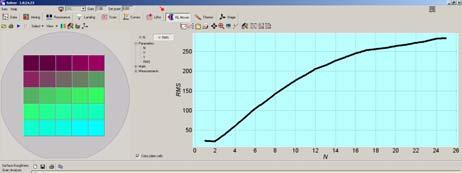
32 Polymer Relaxation Study Experimental: A polymer test grating was heated at the constant rate up to 105 o C, held at this temperature for 5 minutes, then heated further to a maximum temperature of 155 o C. Requires extreme thermal stability >5nm XY drift over 1 hr at 150 o C Results: The general softening of the sample features shown in these images coincides well with the decreasing peak-to to-valley roughness shown in the final graph. Also, note the melting point prior to the final dramatic relaxation. Sample courtesy of Dr. Yen Peng Kong, University of California, Irvine

33 28C 95C 115C 155C
34 Polymer relaxation Polymer relaxation 120 Peak-to-valley [nm] Temperature [C]
35 AFM + Liquid Cells

36 Three approaches to liquid cells Quasi-hermetic flow-through device Hermetically sealed flow-through device Compatible with standard Petri dishes Provides simultaneous optical and AFM observation For experiments in a closed environment
37 The smaller device the better resolution Miniature Liquid Cell for Molecular Resolution


38 Thermally controlled Liquid Cell Heater Petri Dish


39 Images obtained in liquid Block-copolymer Scan size: 0.5x0.5 mm PTFE Scan Size: 2x2 mm


40 STM - Electrochemistry


41 STM Electrochemistry A B C A and B: -50mV Cu crystal growth C: + 30mV Cu crystals dissolved (clear surface) Work Electrode: Cu Substrate: Platinum Electrolyte: H 2 SO 4 +CuSO 4 Scan area: 1x1 μm


42 AFM for the Classroom Scanner Approach mechanism* Base with manual sample positioning Controller PCI/PCMCIA card Nova Software Compact, Robust, Road-worthy
43 New AFM Hybrids

44 AFM/Ultramicrotome Fully integrated AFM plus Ultramicrotome Images directly from the block face, producing pre-aligned serial sections True 3D From the bulk At the nanoscale

45 3D-tomography AFM module scans the surface to make forcecontrasted high resolution image Ultramicrotome module removes thin slice to prepare the surface for next AFM scanning File of 2D AFM images is then reconstructed into the 3D model


46 Ultrastructure TEM image of similar nematode part AFM phase image Nematode section, 10x10 µm. Sample and TEM image courtesy of Dr. M. Mueller and Dr. N. Matsko, ETH Zurich

47 Filled Polymer AFM Topography PS/HIPS blend with silica Scan size: 12x12 µm


48 Composite polymer Inner structure PS/HIPS blend with silica 15 sequential AFM images Each section is 40x20 µm Space between sections: 200 nm (Sample courtesy of Dr. Aliza Tzur, Technion, Israel) 3-D reconstruction: (Can be animated in actual software application)
.. Sample courtesy of Dr. J. P.")
49 3D model of cotton fibers 3D reconstruction Cotton fibers coated with polyelectrolytes. Scan area: um 24 sections Spaces between sections 250 nm).. Sample courtesy of Dr. J. P. Hinestroza, Cornell University.
50 The full workstation Light microscopy Fluorescence Laser Scanning Confocal microscopy (CM) Nearfield Scanning microscopy (NSOM) AFM (40 different techniques) Raman Spectroscopy (Confocal Raman, TERS) Fluorescence Spectroscopy


51 Fully Integrated NTEGRA-TERS LM/CM/AFM/NSOM/ equipment Raman/Fluorescence/TERS Work Station PMT Ext2 AFM\SNOM Heads PC X Y - Stage Ntegra base Objective Z - Scanner Controller


52 Light Microscopy (XP) + AFM Isotactic polypropylene Light Microscopy, X Pol AFM Phase Image Taken from the red inset Scan area: 50 x 50μm


53 SNOM images Mitochondria Shear-force Topography Fluorescence SNOM Scan size: 15x15 μm


54 Carbon nanotubes 1593 cm cm cm -1 AFM Scan size: 5x5 μm R A M A N S P E C T R A
55 TERS Principle Au or Ag coated AFM tip Zone of strong field enhancement Sample Glass wafer To the enhanced Raman signal detection system Tightly focused laser beam Au or Ag coated tip placed 1-2 nm above the sample surface (in semicontact mode) will provide strong Raman signal enhancement (by several orders of magnitude). Au or Ag glass coating creates for additional plasmon resonance enhancement. Because the Raman signal immediately below the tip is much larger than neighboring far-field signals, the whole system resolution is limited only by the zone of field enhancement which in turn depends on the tip size. Multiple modes: Localized, single point spectroscopy Line scan Full image map


 protected with")
56 TERS-active probes 500 nm SEM image of etched silver tip 500 nm SEM image of the cantilever tip with electrochemically deposited Ag nanoparticles (originated from Ag hydrosol) protected with polymer matrix
57 Raman spectra, single-wall SiC nanotubes Intensity, a.u Raman spectrum of SWNT (bulk) TERS spectra of a single nanotube 1595 Tip-on mode 2697 Top: Spectrum from highly concentrated specimen of the SWCNTs (scale: 1/15). Bottom: Spectrum, single SWCNT, without TERS Middle: Spectrum, single SWCNT, with TERS Raman shift, cm -1 Tip-off mode λ ex = 488nm, P ex ~200μW t int =5sec.


 and 2697 cm-1")
58 Simultaneous TERS/AFM imaging AFM image nm 2 1 Raman signal map AFM line profile: Ht = 4.5 nm. Confirms: single nanotube nm TERS image: W, narrow point = 40 nm. TERS images of single SWNT were acquired simultaneously in 1595 cm- 1 (pictured) and 2697 cm-1 Raman bands, with simultaneous AFAM acquisition using TERS-active cantilever.


59 Transmitted light or Epi versions Conventional Transmitted Light Version New High Aperture Head Sees around corners Integrates well
60 Getting started. Coates, J., Ency of Analyt Chem Interpretation of IR spectra JY Raman Tutorial (lists of AFM,FT-IR, and Raman providers) (go to Articles archive) FT-IR Foster, B. AL, Nov 2001 Raman AFM Foster, B., AL, Apr 2003 Foster, B., AL, May 2003 Foster, B., AL, May 2004 (AFAM) Foster, B., AL, May 2005 (AFM + ultramicrotomy) Foster, B., AL, Nov 2005 (Raman/AFM/LM/CM/SNOM)
61 Thanks to Smiths Detection (FT-IR) Horiba JY and Renishaw (Raman confocal) (Go to PRODUCTS, then microscopy) NT-MDT and NTA (AFM) america.com
62 Later this week, this presentation will be available for download from:
Other SPM Techniques. Scanning Probe Microscopy HT10
 Other SPM Techniques Scanning Near-Field Optical Microscopy (SNOM) Scanning Capacitance Microscopy (SCM) Scanning Spreading Resistance Microscopy (SSRM) Multiprobe techniques Electrostatic Force Microscopy,
Scanning Probe Microscopy. Amanda MacMillan, Emmy Gebremichael, & John Shamblin Chem 243: Instrumental Analysis Dr. Robert Corn March 10, 2010
 Scanning Probe Microscopy Amanda MacMillan, Emmy Gebremichael, & John Shamblin Chem 243: Instrumental Analysis Dr. Robert Corn March 10, 2010 Scanning Probe Microscopy High-Resolution Surface Analysis
Instrumentation and Operation
 Instrumentation and Operation 1 STM Instrumentation COMPONENTS sharp metal tip scanning system and control electronics feedback electronics (keeps tunneling current constant) image processing system data
Chapter 12. Nanometrology. Oxford University Press All rights reserved.
 Chapter 12 Nanometrology Introduction Nanometrology is the science of measurement at the nanoscale level. Figure illustrates where nanoscale stands in relation to a meter and sub divisions of meter. Nanometrology
Bringing optics into the nanoscale a double-scanner AFM brings advanced optical experiments within reach
 Bringing optics into the nanoscale a double-scanner AFM brings advanced optical experiments within reach Beyond the diffraction limit The resolution of optical microscopy is generally limited by the diffraction
NTEGRA for EC PRESENTATION
 NTEGRA for EC PRESENTATION Application Purpose: In-situ control/modification of the surface morphology of single crystal and polycrystal electrodes (samples) during electrochemical process (in situ) in
Imaging Methods: Scanning Force Microscopy (SFM / AFM)
") Imaging Methods: Scanning Force Microscopy (SFM / AFM) The atomic force microscope (AFM) probes the surface of a sample with a sharp tip, a couple of microns long and often less than 100 Å in diameter.
Imaging Methods: Scanning Force Microscopy (SFM / AFM) The atomic force microscope (AFM) probes the surface of a sample with a sharp tip, a couple of microns long and often less than 100 Å in diameter.
Low Temperature Physics Measurement Systems
 PAGE 6 & 2008 2007 PRODUCT CATALOG Accelerate your Semiconductor Research & Developments towards Nanoscale Products. Experience your new working horse in the emerging field of semiconductor research for
Basic Laboratory. Materials Science and Engineering. Atomic Force Microscopy (AFM)
") Basic Laboratory Materials Science and Engineering Atomic Force Microscopy (AFM) M108 Stand: 20.10.2015 Aim: Presentation of an application of the AFM for studying surface morphology. Inhalt 1.Introduction...
Basic Laboratory Materials Science and Engineering Atomic Force Microscopy (AFM) M108 Stand: 20.10.2015 Aim: Presentation of an application of the AFM for studying surface morphology. Inhalt 1.Introduction...
Clark Atlanta University Center for Surface Chemistry and Catalysis Instrument Capabilities
 Center for Surface Chemistry and Catalysis Instrument Capabilities For information contact: Dr. Eric Mintz Research Center for Science and Technology Clark Atlanta University Atlanta, Georgia 30314 Phone:
Reducing dimension. Crystalline structures
 Reducing dimension 2D surfaces, interfaces and quantum wells 1D carbon nanotubes, quantum wires and conducting polymers 0D nanocrystals, nanoparticles, lithographically patterned quantum dots Crystalline
Introduction to Scanning Probe Microscopy Zhe Fei
 Introduction to Scanning Probe Microscopy Zhe Fei Phys 590B, Apr. 2019 1 Outline Part 1 SPM Overview Part 2 Scanning tunneling microscopy Part 3 Atomic force microscopy Part 4 Electric & Magnetic force
Chapter 10. Nanometrology. Oxford University Press All rights reserved.
 Chapter 10 Nanometrology Oxford University Press 2013. All rights reserved. 1 Introduction Nanometrology is the science of measurement at the nanoscale level. Figure illustrates where nanoscale stands
Review. Surfaces of Biomaterials. Characterization. Surface sensitivity
 Surfaces of Biomaterials Three lectures: 1.23.05 Surface Properties of Biomaterials 1.25.05 Surface Characterization 1.27.05 Surface and Protein Interactions Review Bulk Materials are described by: Chemical
Nanotechnology Fabrication Methods.
 Nanotechnology Fabrication Methods. 10 / 05 / 2016 1 Summary: 1.Introduction to Nanotechnology:...3 2.Nanotechnology Fabrication Methods:...5 2.1.Top-down Methods:...7 2.2.Bottom-up Methods:...16 3.Conclusions:...19
Kavli Workshop for Journalists. June 13th, CNF Cleanroom Activities
 Kavli Workshop for Journalists June 13th, 2007 CNF Cleanroom Activities Seeing nm-sized Objects with an SEM Lab experience: Scanning Electron Microscopy Equipment: Zeiss Supra 55VP Scanning electron microscopes
Optics and Spectroscopy
 Introduction to Optics and Spectroscopy beyond the diffraction limit Chi Chen 陳祺 Research Center for Applied Science, Academia Sinica 2015Apr09 1 Light and Optics 2 Light as Wave Application 3 Electromagnetic
Atomic Force Microscopy imaging and beyond
 Atomic Force Microscopy imaging and beyond Arif Mumtaz Magnetism and Magnetic Materials Group Department of Physics, QAU Coworkers: Prof. Dr. S.K.Hasanain M. Tariq Khan Alam Imaging and beyond Scanning
And Manipulation by Scanning Probe Microscope
 Basic 15 Nanometer Scale Measurement And Manipulation by Scanning Probe Microscope Prof. K. Fukuzawa Dept. of Micro/Nano Systems Engineering Nagoya University I. Basics of scanning probe microscope Basic
STM: Scanning Tunneling Microscope
 STM: Scanning Tunneling Microscope Basic idea STM working principle Schematic representation of the sample-tip tunnel barrier Assume tip and sample described by two infinite plate electrodes Φ t +Φ s =
Lecture 4 Scanning Probe Microscopy (SPM)
") Lecture 4 Scanning Probe Microscopy (SPM) General components of SPM; Tip --- the probe; Cantilever --- the indicator of the tip; Tip-sample interaction --- the feedback system; Scanner --- piezoelectric
Lecture 4 Scanning Probe Microscopy (SPM) General components of SPM; Tip --- the probe; Cantilever --- the indicator of the tip; Tip-sample interaction --- the feedback system; Scanner --- piezoelectric
Imaging Carbon materials with correlative Raman-SEM microscopy. Introduction. Raman, SEM and FIB within one chamber. Diamond.
 Imaging Carbon materials with correlative Raman-SEM microscopy Application Example Carbon materials are widely used in many industries for their exceptional properties. Electric conductance, light weight,
International Journal of Pure and Applied Sciences and Technology
 Int. J. Pure Appl. Sci. Technol., 9(1) (2012), pp. 1-8 International Journal of Pure and Applied Sciences and Technology ISSN 2229-6107 Available online at www.ijopaasat.in Research Paper Preparation,
Nanostructure. Materials Growth Characterization Fabrication. More see Waser, chapter 2
 Nanostructure Materials Growth Characterization Fabrication More see Waser, chapter 2 Materials growth - deposition deposition gas solid Physical Vapor Deposition Chemical Vapor Deposition Physical Vapor
Contents. What is AFM? History Basic principles and devices Operating modes Application areas Advantages and disadvantages
 Contents What is AFM? History Basic principles and devices Operating modes Application areas Advantages and disadvantages Figure1: 2004 Seth Copen Goldstein What is AFM? A type of Scanning Probe Microscopy
Nanotechnology. Gavin Lawes Department of Physics and Astronomy
 Nanotechnology Gavin Lawes Department of Physics and Astronomy Earth-Moon distance 4x10 8 m (courtesy NASA) Length scales (Part I) Person 2m Magnetic nanoparticle 5x10⁻⁹ m 10 10 m 10 5 m 1 m 10-5 m 10-10
OPTICAL PROPERTIES AND SPECTROSCOPY OF NANOAAATERIALS. Jin Zhong Zhang. World Scientific TECHNISCHE INFORMATIONSBIBLIOTHEK
 OPTICAL PROPERTIES AND SPECTROSCOPY OF NANOAAATERIALS Jin Zhong Zhang University of California, Santa Cruz, USA TECHNISCHE INFORMATIONSBIBLIOTHEK Y World Scientific NEW JERSEY. t'on.don SINGAPORE «'BEIJING
Contents. Principles: Theory and Practice
 Contents Part I Principles: Theory and Practice 1 Physical Principles of Scanning Probe Microscopy Imaging... 3 1.1 Introduction... 3 1.2 The Physical Principles of Atomic Force Microscopy... 4 1.2.1 Forces
The most versatile AFM platform for your nanoscale microscopy needs
 The most versatile AFM platform for your nanoscale microscopy needs Atomic Force Microscopy (AFM) for nanometer resolution imaging with electrical, magnetic, thermal, and mechanical property measurement
Scanning Probe Microscopy. EMSE-515 F. Ernst
 Scanning Probe Microscopy EMSE-515 F. Ernst 1 Literature 2 3 Scanning Probe Microscopy: The Lab on a Tip by Ernst Meyer,Ans Josef Hug,Roland Bennewitz 4 Scanning Probe Microscopy and Spectroscopy : Theory,
General concept and defining characteristics of AFM. Dina Kudasheva Advisor: Prof. Mary K. Cowman
 General concept and defining characteristics of AFM Dina Kudasheva Advisor: Prof. Mary K. Cowman Overview Introduction History of the SPM invention Technical Capabilities Principles of operation Examples
INDIAN INSTITUTE OF TECHNOLOGY ROORKEE NPTEL NPTEL ONLINE CERTIFICATION COURSE. Biomedical Nanotechnology. Lec-05 Characterisation of Nanoparticles
 INDIAN INSTITUTE OF TECHNOLOGY ROORKEE NPTEL NPTEL ONLINE CERTIFICATION COURSE Biomedical Nanotechnology Lec-05 Characterisation of Nanoparticles Dr. P. Gopinath Department of Biotechnology Indian Institute
Electronic Supplementary Information
 Electronic Supplementary Material (ESI) for Journal of Materials Chemistry C. This journal is The Royal Society of Chemistry 2017 Electronic Supplementary Information Polymorphism and microcrystal shape
MS482 Materials Characterization ( 재료분석 ) Lecture Note 11: Scanning Probe Microscopy. Byungha Shin Dept. of MSE, KAIST
 Lecture Note 11: Scanning Probe Microscopy. Byungha Shin Dept. of MSE, KAIST") 2015 Fall Semester MS482 Materials Characterization ( 재료분석 ) Lecture Note 11: Scanning Probe Microscopy Byungha Shin Dept. of MSE, KAIST 1 Course Information Syllabus 1. Overview of various characterization
2015 Fall Semester MS482 Materials Characterization ( 재료분석 ) Lecture Note 11: Scanning Probe Microscopy Byungha Shin Dept. of MSE, KAIST 1 Course Information Syllabus 1. Overview of various characterization
High-resolution Characterization of Organic Ultrathin Films Using Atomic Force Microscopy
 High-resolution Characterization of Organic Ultrathin Films Using Atomic Force Microscopy Jing-jiang Yu Nanotechnology Measurements Division Agilent Technologies, Inc. Atomic Force Microscopy High-Resolution
Università degli Studi di Bari "Aldo Moro"
 Università degli Studi di Bari "Aldo Moro" Table of contents 1. Introduction to Atomic Force Microscopy; 2. Introduction to Raman Spectroscopy; 3. The need for a hybrid technique Raman AFM microscopy;
Characterization of Materials with a Combined AFM/Raman Microscope
 Application Note 089 short Characterization of Materials with a Combined AFM/Raman Microscope Marko Surtchev 1, Sergei Magonov 1 and Mark Wall 2 1 NT-MDT America, Tempe, AZ U.S.A. 2 Thermo Fisher Scientific,
TEOS characterization of 2D materials from graphene to TMDCs
 Marc Chaigneau Yoshito Okuno, Andrey Krayev, Filippo Fabbri HORIBA Scientific AIST-NT Inc. IMEM-CNR Institute TEOS characterization of 2D materials from graphene to TMDCs 30-03-2017 Graphene2017 2015 2017
Nanoscale Chemical Imaging with Photo-induced Force Microscopy
 OG2 BCP39nm_0062 PiFM (LIA1R)Fwd 500 279.1 µv 375 250 nm 500 375 250 125 0 nm 125 219.0 µv Nanoscale Chemical Imaging with Photo-induced Force Microscopy 0 Thomas R. Albrecht, Derek Nowak, Will Morrison,
INTRODUCTION TO SCA\ \I\G TUNNELING MICROSCOPY
 INTRODUCTION TO SCA\ \I\G TUNNELING MICROSCOPY SECOND EDITION C. JULIAN CHEN Department of Applied Physics and Applied Mathematics, Columbia University, New York OXFORD UNIVERSITY PRESS Contents Preface
MSE 321 Structural Characterization
 Auger Spectroscopy Auger Electron Spectroscopy (AES) Scanning Auger Microscopy (SAM) Incident Electron Ejected Electron Auger Electron Initial State Intermediate State Final State Physical Electronics
Improving nano-scale imaging of of intergrated micro-raman/afm systems using negativestiffness
 See vibration isolation technology @ www.minusk.com?pdf) Electronic Products and Technology - May 2014 Improving nano-scale imaging of of intergrated micro-raman/afm systems using negativestiffness vibration
SCANNING-PROBE TECHNIQUES OR APPARATUS; APPLICATIONS OF SCANNING-PROBE TECHNIQUES, e.g. SCANNING PROBE MICROSCOPY [SPM]
![SCANNING-PROBE TECHNIQUES OR APPARATUS; APPLICATIONS OF SCANNING-PROBE TECHNIQUES, e.g. SCANNING PROBE MICROSCOPY [SPM]](/thumbs/81/83165631.jpg "SCANNING-PROBE TECHNIQUES OR APPARATUS; APPLICATIONS OF SCANNING-PROBE TECHNIQUES, e.g. SCANNING PROBE MICROSCOPY [SPM]") G01Q SCANNING-PROBE TECHNIQUES OR APPARATUS; APPLICATIONS OF SCANNING-PROBE TECHNIQUES, e.g. SCANNING PROBE MICROSCOPY [SPM] Scanning probes, i.e. devices having at least a tip of nanometre sized dimensions
G01Q SCANNING-PROBE TECHNIQUES OR APPARATUS; APPLICATIONS OF SCANNING-PROBE TECHNIQUES, e.g. SCANNING PROBE MICROSCOPY [SPM] Scanning probes, i.e. devices having at least a tip of nanometre sized dimensions
Crystalline Surfaces for Laser Metrology
 Crystalline Surfaces for Laser Metrology A.V. Latyshev, Institute of Semiconductor Physics SB RAS, Novosibirsk, Russia Abstract: The number of methodological recommendations has been pronounced to describe
Characterization of MEMS Devices
 MEMS: Characterization Characterization of MEMS Devices Prasanna S. Gandhi Assistant Professor, Department of Mechanical Engineering, Indian Institute of Technology, Bombay, Recap Characterization of MEMS
Low Vibration Cryogenic Equipment
 PAGE 12 PAGE 13 ATTOCUBE S CRYOSTATS ATTODRY attodry1000....................... 14 cryogen-free cryostats with/without s attodry700.........................18 cryogen-free table-top cryostats with optical
Please allow us to demonstrate our capabilities and test us testing your samples!
 We determine properties of surfaces, thin films, and layer structures Hardness Young s modulus Scratch, friction, and wear tests Topography Mapping of thermal, magnetic, and electronic properties Please
Vibrational Spectroscopies. C-874 University of Delaware
 Vibrational Spectroscopies C-874 University of Delaware Vibrational Spectroscopies..everything that living things do can be understood in terms of the jigglings and wigglings of atoms.. R. P. Feymann Vibrational
Scanning Probe Microscopy
 1 Scanning Probe Microscopy Dr. Benjamin Dwir Laboratory of Physics of Nanostructures (LPN) Benjamin.dwir@epfl.ch PH.D3.344 Outline: Introduction: What is SPM, history STM AFM Image treatment Advanced
instruments anasys Nanoscale Thermal Analysis Craig Prater, CTO Research Challenges for Nanomanufacturing Systems Februay th, 2008
 Nanoscale Thermal Analysis Craig Prater, CTO Research Challenges for Nanomanufacturing Systems Februay 11-12 th, 2008 Motivations Nanomanufacturing needs characterization for research, product development
Supplementary information. Derivatization and Interlaminar Debonding of Graphite-Iron Nanoparticles Hybrid
 Electronic Supplementary Material (ESI) for Physical Chemistry Chemical Physics. This journal is the Owner Societies 2017 Supplementary information Derivatization and Interlaminar Debonding of Graphite-Iron
NIS: what can it be used for?
 AFM @ NIS: what can it be used for? Chiara Manfredotti 011 670 8382/8388/7879 chiara.manfredotti@to.infn.it Skype: khiaram 1 AFM: block scheme In an Atomic Force Microscope (AFM) a micrometric tip attached
Scanning Tunneling Microscopy and its Application
 Chunli Bai Scanning Tunneling Microscopy and its Application With 181 Figures SHANGHAI SCIENTIFIC & TECHNICAL PUBLISHERS Jpl Springer Contents 1. Introduction 1 1.1 Advantages of STM Compared with Other
SOLID STATE PHYSICS PHY F341. Dr. Manjuladevi.V Associate Professor Department of Physics BITS Pilani
 SOLID STATE PHYSICS PHY F341 Dr. Manjuladevi.V Associate Professor Department of Physics BITS Pilani 333031 manjula@bits-pilani.ac.in Characterization techniques SEM AFM STM BAM Outline What can we use
Carbon Nanomaterials
 Carbon Nanomaterials STM Image 7 nm AFM Image Fullerenes C 60 was established by mass spectrographic analysis by Kroto and Smalley in 1985 C 60 is called a buckminsterfullerene or buckyball due to resemblance
Secondary Ion Mass Spectrometry (SIMS)
") CHEM53200: Lecture 10 Secondary Ion Mass Spectrometry (SIMS) Major reference: Surface Analysis Edited by J. C. Vickerman (1997). 1 Primary particles may be: Secondary particles can be e s, neutral species
CHEM53200: Lecture 10 Secondary Ion Mass Spectrometry (SIMS) Major reference: Surface Analysis Edited by J. C. Vickerman (1997). 1 Primary particles may be: Secondary particles can be e s, neutral species
The design of an integrated XPS/Raman spectroscopy instrument for co-incident analysis
 The design of an integrated XPS/Raman spectroscopy instrument for co-incident analysis Tim Nunney The world leader in serving science 2 XPS Surface Analysis XPS +... UV Photoelectron Spectroscopy UPS He(I)
Atomic Force Microscopy (AFM) Part I
 Part I") Atomic Force Microscopy (AFM) Part I CHEM-L2000 Eero Kontturi 6 th March 2018 Lectures on AFM Part I Principles and practice Imaging of native materials, including nanocellulose Part II Surface force measurements
Atomic Force Microscopy (AFM) Part I CHEM-L2000 Eero Kontturi 6 th March 2018 Lectures on AFM Part I Principles and practice Imaging of native materials, including nanocellulose Part II Surface force measurements
Supporting Information s for
 Supporting Information s for # Self-assembling of DNA-templated Au Nanoparticles into Nanowires and their enhanced SERS and Catalytic Applications Subrata Kundu* and M. Jayachandran Electrochemical Materials
There's Plenty of Room at the Bottom
 There's Plenty of Room at the Bottom 12/29/1959 Feynman asked why not put the entire Encyclopedia Britannica (24 volumes) on a pin head (requires atomic scale recording). He proposed to use electron microscope
Nano fabrication and optical characterization of nanostructures
 Introduction to nanooptics, Summer Term 2012, Abbe School of Photonics, FSU Jena, Prof. Thomas Pertsch Nano fabrication and optical characterization of nanostructures Lecture 12 1 Optical characterization
CHARACTERIZATION of NANOMATERIALS KHP
 CHARACTERIZATION of NANOMATERIALS Overview of the most common nanocharacterization techniques MAIN CHARACTERIZATION TECHNIQUES: 1.Transmission Electron Microscope (TEM) 2. Scanning Electron Microscope
Optical imaging of metallic and semiconductor nanostructures at sub wavelength regime
 Optical imaging of metallic and semiconductor nanostructures at sub wavelength regime A. K. Sivadasan 1, Kishore K. Madapu 1 and Prajit Dhara 2 1 Nanomaterials Characterization and Sensors Section, Surface
Scattering-type near-field microscopy for nanoscale optical imaging
 Scattering-type near-field microscopy for nanoscale optical imaging Rainer Hillenbrand Nano-Photonics Group Max-Planck-Institut für Biochemie 82152 Martinsried, Germany Infrared light enables label-free
29: Nanotechnology. What is Nanotechnology? Properties Control and Understanding. Nanomaterials
 29: Nanotechnology What is Nanotechnology? Properties Control and Understanding Nanomaterials Making nanomaterials Seeing at the nanoscale Quantum Dots Carbon Nanotubes Biology at the Nanoscale Some Applications
Nanomaterials and their Optical Applications
 Nanomaterials and their Optical Applications Winter Semester 2013 Lecture 02 rachel.grange@uni-jena.de http://www.iap.uni-jena.de/multiphoton Lecture 2: outline 2 Introduction to Nanophotonics Theoretical
Magnetic Resonance Force Microscopy. Christian Degen Department of Physics, ETH Zurich, Switzerland
 Magnetic Resonance Force Microscopy Christian Degen Department of Physics, ETH Zurich, Switzerland CIMST Summer School 2014 From Andreas Trabesinger / Wikipedia Scale of things 1m 1mm 1µm 1-100 nm 1nm
Accurate thickness measurement of graphene
 Accurate thickness measurement of graphene Cameron J Shearer *, Ashley D Slattery, Andrew J Stapleton, Joseph G Shapter and Christopher T Gibson * Centre for NanoScale Science and Technology, School of
Magnetic Force Microscopy (MFM) F = µ o (m )H
 F = µ o (m )H") Magnetic Force Microscopy (MFM) F = µ o (m )H 1. MFM is based on the use of a ferromagnetic tip as a local field sensor. Magnetic interaction between the tip and the surface results in a force acting on
Magnetic Force Microscopy (MFM) F = µ o (m )H 1. MFM is based on the use of a ferromagnetic tip as a local field sensor. Magnetic interaction between the tip and the surface results in a force acting on
Spectroscopy at nanometer scale
 Spectroscopy at nanometer scale 1. Physics of the spectroscopies 2. Spectroscopies for the bulk materials 3. Experimental setups for the spectroscopies 4. Physics and Chemistry of nanomaterials Various
Scanning Probe Microscopy (SPM)
") http://ww2.sljus.lu.se/staff/rainer/spm.htm Scanning Probe Microscopy (FYST42 / FAFN30) Scanning Probe Microscopy (SPM) overview & general principles March 23 th, 2018 Jan Knudsen, room K522, jan.knudsen@sljus.lu.se
http://ww2.sljus.lu.se/staff/rainer/spm.htm Scanning Probe Microscopy (FYST42 / FAFN30) Scanning Probe Microscopy (SPM) overview & general principles March 23 th, 2018 Jan Knudsen, room K522, jan.knudsen@sljus.lu.se
Outline Scanning Probe Microscope (SPM)
") AFM Outline Scanning Probe Microscope (SPM) A family of microscopy forms where a sharp probe is scanned across a surface and some tip/sample interactions are monitored Scanning Tunneling Microscopy (STM)
AFM Outline Scanning Probe Microscope (SPM) A family of microscopy forms where a sharp probe is scanned across a surface and some tip/sample interactions are monitored Scanning Tunneling Microscopy (STM)
Graphene Fundamentals and Emergent Applications
 Graphene Fundamentals and Emergent Applications Jamie H. Warner Department of Materials University of Oxford Oxford, UK Franziska Schaffel Department of Materials University of Oxford Oxford, UK Alicja
XPS & Scanning Auger Principles & Examples
 XPS & Scanning Auger Principles & Examples Shared Research Facilities Lunch Talk Contact info: dhu Pujari & Han Zuilhof Lab of rganic Chemistry Wageningen University E-mail: dharam.pujari@wur.nl Han.Zuilhof@wur.nl
MSE 321 Structural Characterization
 Auger Spectroscopy Auger Electron Spectroscopy (AES) Scanning Auger Microscopy (SAM) Incident Electron Ejected Electron Auger Electron Initial State Intermediate State Final State Physical Electronics
NANOSCIENCE: TECHNOLOGY AND ADVANCED MATERIALS
 UNIVERSITY OF SOUTHAMPTON PHYS6014W1 SEMESTER 2 EXAMINATIONS 2012-2013 NANOSCIENCE: TECHNOLOGY AND ADVANCED MATERIALS DURATION 120 MINS (2 Hours) This paper contains 8 questions Answer ALL questions in
Nanomaterials and their Optical Applications
 Nanomaterials and their Optical Applications Winter Semester 2012 Lecture 04 rachel.grange@uni-jena.de http://www.iap.uni-jena.de/multiphoton Lecture 4: outline 2 Characterization of nanomaterials SEM,
Nanoscale Chemical Characterization: Moving to 3 Dimensions
 Nanoscale Chemical Characterization: Moving to 3 Dimensions Eric B. Steel Chemical Science & Technology Laboratory National Institute of Standards & Technology Outline What is and why do we need chemical
Highly efficient SERS test strips
 Electronic Supplementary Information (ESI) for Highly efficient SERS test strips 5 Ran Zhang, a Bin-Bin Xu, a Xue-Qing Liu, a Yong-Lai Zhang, a Ying Xu, a Qi-Dai Chen, * a and Hong-Bo Sun* a,b 5 10 Experimental
Remote Access to Hi-tech Equipment
 Remote Access to Hi-tech Equipment From Your Classroom to Ours Sebastien Maeder Outline What is Remote Access? The Method vs. the Goal The role within NACK Why should we try? Confines of Classroom Characterization
Scanning Probe Microscopy (SPM)
") Scanning Probe Microscopy (SPM) Scanning Tunneling Microscopy (STM) --- G. Binnig, H. Rohrer et al, (1982) Near-Field Scanning Optical Microscopy (NSOM) --- D. W. Pohl (1982) Atomic Force Microscopy (AFM)
Scanning Probe Microscopy (SPM) Scanning Tunneling Microscopy (STM) --- G. Binnig, H. Rohrer et al, (1982) Near-Field Scanning Optical Microscopy (NSOM) --- D. W. Pohl (1982) Atomic Force Microscopy (AFM)
Journal of Optoelectronics and Biomedical Materials Vol. 9, No.1, January - March 2017 p. 1-7
 Journal of Optoelectronics and Biomedical Materials Vol. 9, No.1, January - March 2017 p. 1-7 INFLUENCE TEMPERATURE TIME MODE OF CRYSTALLIZATION ON THE STRUCTURE AND PROPERTIES OF NANOCOMPOSITES BASED
Characterization Tools
 Lectures in Nanoscience & Technology Characterization Tools K. Sakkaravarthi Department of Physics National Institute of Technology Tiruchirappalli 620 015 Tamil Nadu India sakkaravarthi@nitt.edu ksakkaravarthi.weebly.com
From nanophysics research labs to cell phones. Dr. András Halbritter Department of Physics associate professor
 From nanophysics research labs to cell phones Dr. András Halbritter Department of Physics associate professor Curriculum Vitae Birth: 1976. High-school graduation: 1994. Master degree: 1999. PhD: 2003.
Fabrication at the nanoscale for nanophotonics
 Fabrication at the nanoscale for nanophotonics Ilya Sychugov, KTH Materials Physics, Kista silicon nanocrystal by electron beam induced deposition lithography Outline of basic nanofabrication methods Devices
Supporting Information. Fast Synthesis of High-Performance Graphene by Rapid Thermal Chemical Vapor Deposition
 1 Supporting Information Fast Synthesis of High-Performance Graphene by Rapid Thermal Chemical Vapor Deposition Jaechul Ryu, 1,2, Youngsoo Kim, 4, Dongkwan Won, 1 Nayoung Kim, 1 Jin Sung Park, 1 Eun-Kyu
Aluminum for nonlinear plasmonics: Methods Section
 Aluminum for nonlinear plasmonics: Methods Section Marta Castro-Lopez, Daan Brinks, Riccardo Sapienza, and Niek F. van Hulst, ICFO - Institut de Ciencies Fotoniques, and ICREA - Institució Catalana de
Improving Micro-Raman/AFM Systems Imaging Using Negative-Stiffness Vibration Isolation
 Photonics.com - February 2011 Improving Micro-Raman/AFM Systems Imaging Using Negative-Stiffness Vibration Isolation Negative-stiffness vibration isolators can easily support the heavy weight of a combined
AFM for Measuring Surface Topography and Forces
 ENB 2007 07.03.2007 AFM for Measuring Surface Topography and Forces Andreas Fery Scanning Probe : What is it and why do we need it? AFM as a versatile tool for local analysis and manipulation Dates Course
Scanning Probe Microscopy: Atomic Force Microscopy And Scanning Tunneling Microscopy (NanoScience And Technology) [Kindle Edition] By Bert Voigtl
![Scanning Probe Microscopy: Atomic Force Microscopy And Scanning Tunneling Microscopy (NanoScience And Technology) [Kindle Edition] By Bert Voigtl](/thumbs/81/83165600.jpg "Scanning Probe Microscopy: Atomic Force Microscopy And Scanning Tunneling Microscopy (NanoScience And Technology) [Kindle Edition] By Bert Voigtl") Scanning Probe Microscopy: Atomic Force Microscopy And Scanning Tunneling Microscopy (NanoScience And Technology) [Kindle Edition] By Bert Voigtl READ ONLINE If searched for a book Scanning Probe Microscopy:
Scanning Probe Microscopy: Atomic Force Microscopy And Scanning Tunneling Microscopy (NanoScience And Technology) [Kindle Edition] By Bert Voigtl READ ONLINE If searched for a book Scanning Probe Microscopy:
TERS Ready or Not? by Barbara Foster. Reprinted from American Laboratory September
 by Barbara Foster Reprinted from American Laboratory September 2016 AL TERS Ready or Not? Tip-enhanced Raman spectroscopy, or TERS, integrates scanning probe microscopy (SPM) for nano-scale imaging with
Spring 2009 EE 710: Nanoscience and Engineering
 Spring 2009 EE 710: Nanoscience and Engineering Part 1: Introduction Course Texts: Bhushan, Springer Handbook of Nanotechnology 2 nd ed., Springer 2007 Hornyak, et.al, Introduction ti to Nanoscience, CRC
Nanosphere Lithography
 Nanosphere Lithography Derec Ciafre 1, Lingyun Miao 2, and Keita Oka 1 1 Institute of Optics / 2 ECE Dept. University of Rochester Abstract Nanosphere Lithography is quickly emerging as an efficient, low
6. Plasmon coupling between a flat gold interface and gold nanoparticles.
 6. Plasmon coupling between a flat gold interface and gold nanoparticles. 6.1. Introduction In this outlook oriented chapter the applicability of the multilayered system used in chapter 4.1., for the study
Contents. Foreword by Darrell H. Reneker
 Table of Foreword by Darrell H. Reneker Preface page xi xiii 1 Introduction 1 1.1 How big is a nanometer? 1 1.2 What is nanotechnology? 1 1.3 Historical development of nanotechnology 2 1.4 Classification
Nanophysics: Main trends
 Nano-opto-electronics Nanophysics: Main trends Nanomechanics Main issues Light interaction with small structures Molecules Nanoparticles (semiconductor and metallic) Microparticles Photonic crystals Nanoplasmonics
A Plasmonic Photocatalyst Consisting of Silver Nanoparticles Embedded in Titanium Dioxide. Ryan Huschka LANP Seminar February 19, 2008
 A Plasmonic Photocatalyst Consisting of Silver Nanoparticles Embedded in Titanium Dioxide Ryan Huschka LANP Seminar February 19, 2008 TiO 2 Applications White Pigment Photocatalyst Previous methods to
GRAPHENE ON THE Si-FACE OF SILICON CARBIDE USER MANUAL
 GRAPHENE ON THE Si-FACE OF SILICON CARBIDE USER MANUAL 1. INTRODUCTION Silicon Carbide (SiC) is a wide band gap semiconductor that exists in different polytypes. The substrate used for the fabrication
nano-ta: Nano Thermal Analysis
 nano-ta: Nano Thermal Analysis Application Note #1 Failure Analysis - Identification of Particles in a Polymer Film Author: David Grandy Ph.D. Introduction Nano-TA is a local thermal analysis technique
NANONICS IMAGING FOUNTAIN PEN
 NANONICS IMAGING FOUNTAIN PEN NanoLithography Systems Methods of Nanochemical Lithography Fountain Pen NanoLithography A. Lewis et al. Appl. Phys. Lett. 75, 2689 (1999) FPN controlled etching of chrome.