PumpTech Customer Education
|
|
|
- Joshua Knight
- 5 years ago
- Views:
Transcription

1 PumpTech Customer Education Bellevue Moses Lake Canby


2 PumpTech Product Lines UL Listed Packaged Systems

3 Two full time Mechanical Engineers Licensed in OR, WA & ID SolidWorks & E-Drawings Viewer AutoCad Compatible Drawings All Systems UL QCZJ Listed Designed to HI Standards
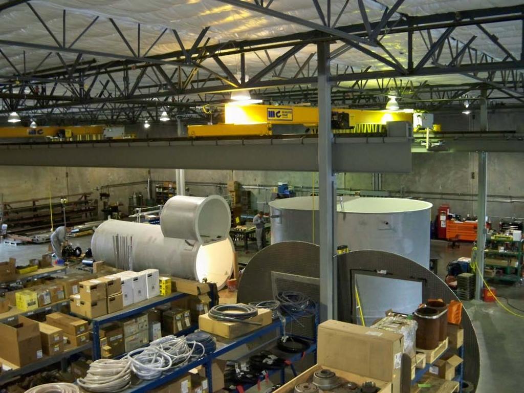
4 Manufacturing Facility Canby, OR

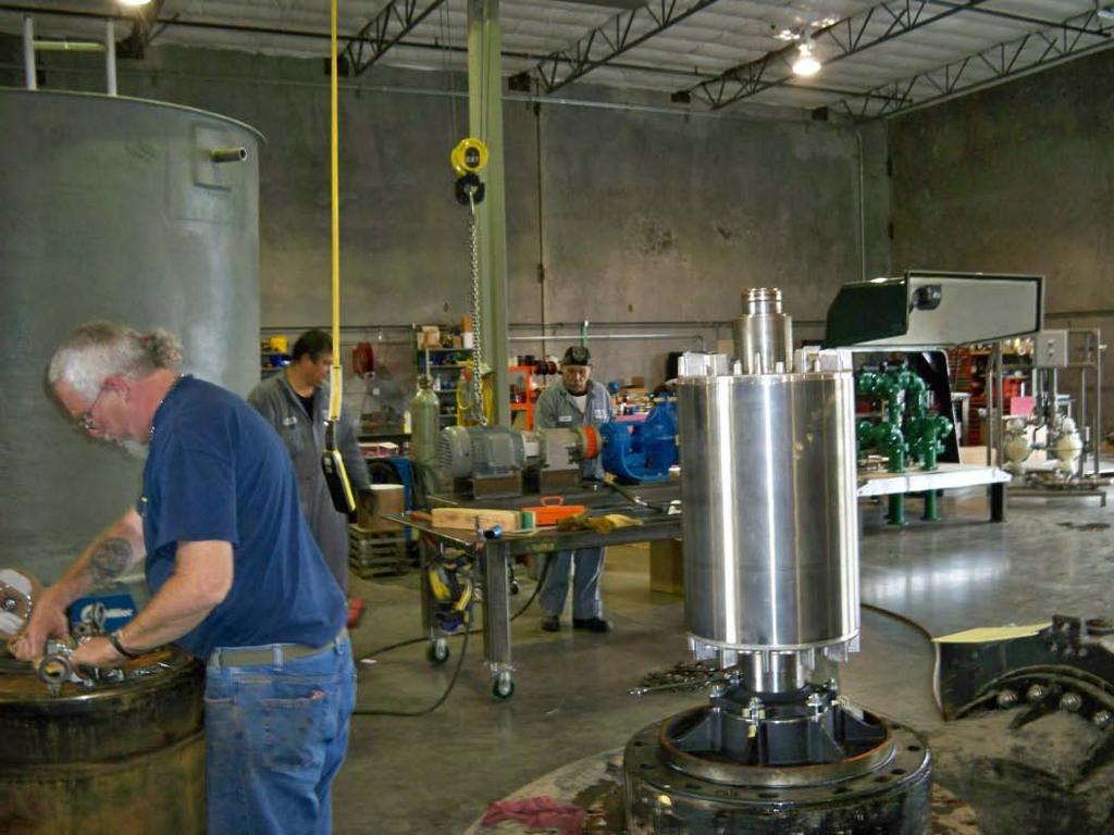
5 Installation, Maintenance & Repair 9 Full Time Service Technicians 3 Full Service Shops 6 Service Trucks 23 Ton Crane Truck 8 Ton Crane Truck 3 Ton Crane Truck 2 Ton Flatbed & Trailer 1 Ton Flatbed & Trailer

6 Pipeline
7 Pump Ed 101 Joe Evans, Ph.D Velocity Head
8 Hint * Centrifugal Pump Impeller Discharge Suction Cutwater Volute What Type of Energy is Added by the Impeller?
9 * Centrifugal Force It is defined as center fleeing
10 * Centrifugal Force Instead it actually moves in the same direction it was traveling at the exact instant it is released. When an object is traveling in a circle, it is actually moving in a straight line at any single point in time.

11 So, How Does It Work? * 1 Rotation of the impeller forces water from its entry point, at the eye, into its vanes. 2 Water moving through the vanes creates a partial vacuum at the eye allowing atmospheric, or some other outside pressure, to force more water into the eye. 3 As water travels through the vanes, it gains rotational velocity (kinetic energy) and reaches its maximum velocity just as it exits the vanes. 4 Upon exiting the vanes, water enters the volute where its kinetic energy of motion is transformed into pressure energy.
12 Linear versus Rotational Motion * Speed = d / t Rotational Speed (w) = rotations / t Linear Speed (v) radius (r) x w
13 * Linear Velocity in a Rotational Frame of Reference On the disc to the right there are two points, one at 6 from its center and one at 12. The circle described at 6 has a circumference of 37.7 and the one at 12 a circumference of At a speed of one rotation per second a point 12 from the center will travel twice the distance of a point that is 6 from the center. Therefore its velocity is twice as great. v = C x w
14 Water Energy * Water Can Possess Three Forms of Hydraulic Energy Potential Energy Due to Elevation Kinetic Energy Due to Velocity Pressure Energy Due to Weight (force) These Three Forms of Energy Must Live In Harmony Conservation of Energy
15 * Conservation of Energy Bernoulli s theorem states that, during steady flow, the energy at any point in a conduit is the sum of the velocity head, pressure head, and elevation head. It also states that this sum will remain constant if there are no losses. Daniel Bernoulli H = v + p + z = Constant 50 PSI 50 PSI 48 PSI 100 GPM
16 Daniel Bernoulli Hydrodynamica * Energy = v + P + z = Constant

17 Energy = v + P + z = Constant * Piezometer Measurement

18 Energy = v + P + z = Constant * Piezometer & Pitot Tube Measurement

19 Energy = v + P + z = Constant *
20 Total Dynamic Head What is the Total Head produced by a centrifugal pump? Total Head
21 Total Dynamic Head Total Dynamic Head H = h d - h s Where: h d = discharge head h s = suction head Total Suction Head h s = ± h gs + h vs ± Z s Total Discharge Head h d = h gd + h vd ± Z d Where: h g = gauge head h v = velocity head Z = gauge distance above or below datum Total Head
22 Velocity Head What is the effect of velocity? KE = 1/2mv 2 Falling Body Equation Velocity Head Equation V 2 = 2gh h = V 2 / 2g At a Velocity of 8 ft/sec h = 1 Total Head

23 The Performance Curve BEBOP BEP
.")
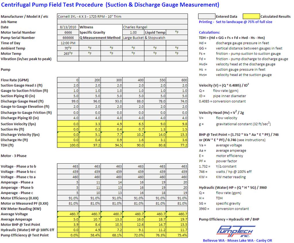
24 Pump Testing TDH Error 4.7% TDH Error 0.6% 3X4 End Suction GPM Velocity 3 = 28.2 ft/sec Velocity 5 = 10.4 ft/sec h v = V 2 / 2g 3 Section h v = 12.4 ft 5 Section h v = 1.7 ft Total Head Actual 3 Pressure = PSI (259.6 ft). Actual 5 Pressure = PSI (260 ft)
 Corrected for Friction = 10.8 (4.7 PSI) Corrected for Elevation = 20.8 (9 PSI) Corrected for Velocity Head (v = 16.4 ft/sec) = 25 (10.")
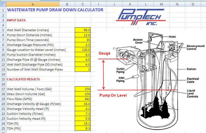
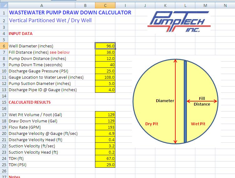
25 * Pump Testing Lift Station Pump (10.8 PSI) 4 Discharge Piping 10 ft Gauge Reading at Valve Box = 6.6 (2.8 PSI) Corrected for Friction = 10.8 (4.7 PSI) Corrected for Elevation = 20.8 (9 PSI) Corrected for Velocity Head (v = 16.4 ft/sec) = 25 (10.8 PSI) TDH Error Ignoring Velocity Head = 19%
26 *
27 *
28 *
29 *
30 *
31 Pump Ed 101 Joe Evans, Ph.D Velocity Head
Pressure and Flow Characteristics
 Pressure and Flow Characteristics Continuing Education from the American Society of Plumbing Engineers August 2015 ASPE.ORG/ReadLearnEarn CEU 226 READ, LEARN, EARN Note: In determining your answers to
Chapter Four Hydraulic Machines
 Contents 1- Introduction. - Pumps. Chapter Four Hydraulic Machines (لفرع الميكانيك العام فقط ( Turbines. -3 4- Cavitation in hydraulic machines. 5- Examples. 6- Problems; sheet No. 4 (Pumps) 7- Problems;
Chapter Four Hydraulic Machines
 Contents 1- Introduction. 2- Pumps. Chapter Four Hydraulic Machines (لفرع الميكانيك العام فقط ( Turbines. -3 4- Cavitation in hydraulic machines. 5- Examples. 6- Problems; sheet No. 4 (Pumps) 7- Problems;
CHAPTER EIGHT P U M P I N G O F L I Q U I D S
 CHAPTER EIGHT P U M P I N G O F L I Q U I D S Pupmps are devices for supplying energy or head to a flowing liquid in order to overcome head losses due to friction and also if necessary, to raise liquid
Pumping Stations Design For Infrastructure Master Program Engineering Faculty-IUG
 umping Stations Design For Infrastructure Master rogram Engineering Faculty-IUG Lecture : umping Hydraulics Dr. Fahid Rabah Water and environment Engineering frabah@iugaza.edu The main items that will
COURSE CODE : 3072 COURSE CATEGORY : B PERIODS/ WEEK : 5 PERIODS/ SEMESTER : 75 CREDIT : 5 TIME SCHEDULE
 COURSE TITLE : FLUID MECHANICS COURSE CODE : 307 COURSE CATEGORY : B PERIODS/ WEEK : 5 PERIODS/ SEMESTER : 75 CREDIT : 5 TIME SCHEDULE MODULE TOPIC PERIOD 1 Properties of Fluids 0 Fluid Friction and Flow
Department of Energy Fundamentals Handbook. THERMODYNAMICS, HEAT TRANSFER, AND FLUID FLOW, Module 3 Fluid Flow
 Department of Energy Fundamentals Handbook THERMODYNAMICS, HEAT TRANSFER, AND FLUID FLOW, Module 3 REFERENCES REFERENCES Streeter, Victor L., Fluid Mechanics, 5th Edition, McGraw-Hill, New York, ISBN 07-062191-9.
Applied Fluid Mechanics
 Applied Fluid Mechanics 1. The Nature of Fluid and the Study of Fluid Mechanics 2. Viscosity of Fluid 3. Pressure Measurement 4. Forces Due to Static Fluid 5. Buoyancy and Stability 6. Flow of Fluid and
Lecture 3 The energy equation
 Lecture 3 The energy equation Dr Tim Gough: t.gough@bradford.ac.uk General information Lab groups now assigned Timetable up to week 6 published Is there anyone not yet on the list? Week 3 Week 4 Week 5
EXPERIMENT No.1 FLOW MEASUREMENT BY ORIFICEMETER
 EXPERIMENT No.1 FLOW MEASUREMENT BY ORIFICEMETER 1.1 AIM: To determine the co-efficient of discharge of the orifice meter 1.2 EQUIPMENTS REQUIRED: Orifice meter test rig, Stopwatch 1.3 PREPARATION 1.3.1
Chapter (6) Energy Equation and Its Applications
 Energy Equation and Its Applications") Chapter (6) Energy Equation and Its Applications Bernoulli Equation Bernoulli equation is one of the most useful equations in fluid mechanics and hydraulics. And it s a statement of the principle of conservation
Chapter (6) Energy Equation and Its Applications Bernoulli Equation Bernoulli equation is one of the most useful equations in fluid mechanics and hydraulics. And it s a statement of the principle of conservation
9. Pumps (compressors & turbines) Partly based on Chapter 10 of the De Nevers textbook.
 Partly based on Chapter 10 of the De Nevers textbook.") Lecture Notes CHE 31 Fluid Mechanics (Fall 010) 9. Pumps (compressors & turbines) Partly based on Chapter 10 of the De Nevers textbook. Basics (pressure head, efficiency, working point, stability) Pumps
Lecture Notes CHE 31 Fluid Mechanics (Fall 010) 9. Pumps (compressors & turbines) Partly based on Chapter 10 of the De Nevers textbook. Basics (pressure head, efficiency, working point, stability) Pumps
Rate of Flow Quantity of fluid passing through any section (area) per unit time
 per unit time") Kinematics of Fluid Flow Kinematics is the science which deals with study of motion of liquids without considering the forces causing the motion. Rate of Flow Quantity of fluid passing through any section
Kinematics of Fluid Flow Kinematics is the science which deals with study of motion of liquids without considering the forces causing the motion. Rate of Flow Quantity of fluid passing through any section
LECTURE 6- ENERGY LOSSES IN HYDRAULIC SYSTEMS SELF EVALUATION QUESTIONS AND ANSWERS
 LECTURE 6- ENERGY LOSSES IN HYDRAULIC SYSTEMS SELF EVALUATION QUESTIONS AND ANSWERS 1. What is the head loss ( in units of bars) across a 30mm wide open gate valve when oil ( SG=0.9) flow through at a
Fluid Mechanics II 3 credit hour. Fluid flow through pipes-minor losses
 COURSE NUMBER: ME 323 Fluid Mechanics II 3 credit hour Fluid flow through pipes-minor losses Course teacher Dr. M. Mahbubur Razzaque Professor Department of Mechanical Engineering BUET 1 Losses in Noncircular
Objectives. Conservation of mass principle: Mass Equation The Bernoulli equation Conservation of energy principle: Energy equation
 Objectives Conservation of mass principle: Mass Equation The Bernoulli equation Conservation of energy principle: Energy equation Conservation of Mass Conservation of Mass Mass, like energy, is a conserved
2.The lines that are tangent to the velocity vectors throughout the flow field are called steady flow lines. True or False A. True B.
 CHAPTER 03 1. Write Newton's second law of motion. YOUR ANSWER: F = ma 2.The lines that are tangent to the velocity vectors throughout the flow field are called steady flow lines. True or False 3.Streamwise
CHAPTER 3 BASIC EQUATIONS IN FLUID MECHANICS NOOR ALIZA AHMAD
 CHAPTER 3 BASIC EQUATIONS IN FLUID MECHANICS 1 INTRODUCTION Flow often referred as an ideal fluid. We presume that such a fluid has no viscosity. However, this is an idealized situation that does not exist.
vector H. If O is the point about which moments are desired, the angular moment about O is given:
 The angular momentum A control volume analysis can be applied to the angular momentum, by letting B equal to angularmomentum vector H. If O is the point about which moments are desired, the angular moment
Chemical Engineering 3P04 Process Control Tutorial # 1 Learning goals
 Chemical Engineering 3P04 Process Control Tutorial # 1 Learning goals 1. Sensor Principles with the flow sensor example 2. The typical manipulated variable: flow through a conduit Sensors: We need them
Mechanical Engineering Programme of Study
 Mechanical Engineering Programme of Study Fluid Mechanics Instructor: Marios M. Fyrillas Email: eng.fm@fit.ac.cy SOLVED EXAMPLES ON VISCOUS FLOW 1. Consider steady, laminar flow between two fixed parallel
Hydraulic (Piezometric) Grade Lines (HGL) and
 Grade Lines (HGL) and") Hydraulic (Piezometric) Grade Lines (HGL) and Energy Grade Lines (EGL) When the energy equation is written between two points it is expresses as in the form of: Each term has a name and all terms have
Hydraulic (Piezometric) Grade Lines (HGL) and Energy Grade Lines (EGL) When the energy equation is written between two points it is expresses as in the form of: Each term has a name and all terms have
WATER DISTRIBUTION NETWORKS
 WATER DISTRIBUTION NETWORKS CE 370 1 Components of Water Supply System 2 1 Water Distribution System Water distribution systems are designed to adequately satisfy the water requirements for a combinations
Introduction to Fluid Machines, and Compressible Flow Prof. S. K. Som Department of Mechanical Engineering Indian Institute of Technology, Kharagpur
 Introduction to Fluid Machines, and Compressible Flow Prof. S. K. Som Department of Mechanical Engineering Indian Institute of Technology, Kharagpur Lecture - 09 Introduction to Reaction Type of Hydraulic
Northern Lesson 2 Gear Pump Terminology. Gear Pump 101. Lesson 2: Gear Pump Terminology. When your reputation depends on it!
 Gear Pump 101 Lesson 2: Gear Pump Terminology When your reputation depends on it! Symbol Term Metric Unit Abbreviation US Customary Unit Abbreviation Conversion factor a A Area square millimeter mm2 square
New Website: M P E il Add. Mr. Peterson s Address:
 Brad Peterson, P.E. New Website: http://njut009fall.weebly.com M P E il Add Mr. Peterson s Email Address: bradpeterson@engineer.com If 6 m 3 of oil weighs 47 kn calculate its If 6 m 3 of oil weighs 47
Fluid Mechanics. du dy
 FLUID MECHANICS Technical English - I 1 th week Fluid Mechanics FLUID STATICS FLUID DYNAMICS Fluid Statics or Hydrostatics is the study of fluids at rest. The main equation required for this is Newton's
Basic Fluid Mechanics
 Basic Fluid Mechanics Chapter 5: Application of Bernoulli Equation 4/16/2018 C5: Application of Bernoulli Equation 1 5.1 Introduction In this chapter we will show that the equation of motion of a particle
Chapter 4 DYNAMICS OF FLUID FLOW
 Faculty Of Engineering at Shobra nd Year Civil - 016 Chapter 4 DYNAMICS OF FLUID FLOW 4-1 Types of Energy 4- Euler s Equation 4-3 Bernoulli s Equation 4-4 Total Energy Line (TEL) and Hydraulic Grade Line
For example an empty bucket weighs 2.0kg. After 7 seconds of collecting water the bucket weighs 8.0kg, then:
 Hydraulic Coefficient & Flow Measurements ELEMENTARY HYDRAULICS National Certificate in Technology (Civil Engineering) Chapter 3 1. Mass flow rate If we want to measure the rate at which water is flowing
FE Fluids Review March 23, 2012 Steve Burian (Civil & Environmental Engineering)
") Topic: Fluid Properties 1. If 6 m 3 of oil weighs 47 kn, calculate its specific weight, density, and specific gravity. 2. 10.0 L of an incompressible liquid exert a force of 20 N at the earth s surface.
Topic: Fluid Properties 1. If 6 m 3 of oil weighs 47 kn, calculate its specific weight, density, and specific gravity. 2. 10.0 L of an incompressible liquid exert a force of 20 N at the earth s surface.
Properties and Definitions Useful constants, properties, and conversions
 Properties and Definitions Useful constants, properties, and conversions gc = 32.2 ft/sec 2 [lbm-ft/lbf-sec 2 ] ρwater = 1.96 slugs/ft 3 γwater = 62.4 lb/ft 3 1 ft 3 /sec = 449 gpm 1 mgd = 1.547 ft 3 /sec
1-Reynold s Experiment
 Lect.No.8 2 nd Semester Flow Dynamics in Closed Conduit (Pipe Flow) 1 of 21 The flow in closed conduit ( flow in pipe ) is differ from this occur in open channel where the flow in pipe is at a pressure
THE APPLICATION OF THERMODYNAMICS TO PUMP SYSTEMS
 THE APPLICATION OF THERMODYNAMICS TO PUMP SYSTEMS.0 ENERGY AND THERMODYNAMIC PROPERTIES This chapter requires some introduction to thermodynamic properties and states. No need to panic, we will use only
PUMP PERFORMANCE MEASUREMENTS Jacques Chaurette p. eng. April 2003
 PUMP PERFORMANCE MEASUREMENTS Jacques Chaurette p. eng. www.lightmypump.com April 003 Synopsis This article examines how to take flow and pressure measurement and then calculate the total head of a pump
CONCEPTS AND DEFINITIONS. Prepared by Engr. John Paul Timola
 CONCEPTS AND DEFINITIONS Prepared by Engr. John Paul Timola ENGINEERING THERMODYNAMICS Science that involves design and analysis of devices and systems for energy conversion Deals with heat and work and
Exam #2: Fluid Kinematics and Conservation Laws April 13, 2016, 7:00 p.m. 8:40 p.m. in CE 118
 CVEN 311-501 (Socolofsky) Fluid Dynamics Exam #2: Fluid Kinematics and Conservation Laws April 13, 2016, 7:00 p.m. 8:40 p.m. in CE 118 Name: : UIN: : Instructions: Fill in your name and UIN in the space
FLOW MEASUREMENT IN PIPES EXPERIMENT
 University of Leicester Engineering Department FLOW MEASUREMENT IN PIPES EXPERIMENT Page 1 FORMAL LABORATORY REPORT Name of the experiment: FLOW MEASUREMENT IN PIPES Author: Apollin nana chaazou Partner
Thermal & Fluids PE Exam Technical Study Guide Errata
 Thermal & Fluids PE Exam Technical Study Guide Errata This product has been updated to incorporate all changes shown in the comments on the webpage and email comments as of October, 30 2017. If you have
5 ENERGY EQUATION OF FLUID MOTION
 5 ENERGY EQUATION OF FLUID MOTION 5.1 Introduction In order to develop the equations that describe a flow, it is assumed that fluids are subject to certain fundamental laws of physics. The pertinent laws
V/ t = 0 p/ t = 0 ρ/ t = 0. V/ s = 0 p/ s = 0 ρ/ s = 0
 UNIT III FLOW THROUGH PIPES 1. List the types of fluid flow. Steady and unsteady flow Uniform and non-uniform flow Laminar and Turbulent flow Compressible and incompressible flow Rotational and ir-rotational
TOTAL HEAD, N.P.S.H. AND OTHER CALCULATION EXAMPLES Jacques Chaurette p. eng., June 2003
 TOTAL HEAD, N.P.S.H. AND OTHER CALCULATION EXAMPLES Jacques Chaurette p. eng., www.lightmypump.com June 2003 Figure 1 Calculation example flow schematic. Situation Water at 150 F is to be pumped from a
PART II. Fluid Mechanics Pressure. Fluid Mechanics Pressure. Fluid Mechanics Specific Gravity. Some applications of fluid mechanics
 ART II Some applications of fluid mechanics Fluid Mechanics ressure ressure = F/A Units: Newton's per square meter, Nm -, kgm - s - The same unit is also known as a ascal, a, i.e. a = Nm - ) English units:
Nicholas J. Giordano. Chapter 10 Fluids
 Nicholas J. Giordano www.cengage.com/physics/giordano Chapter 10 Fluids Fluids A fluid may be either a liquid or a gas Some characteristics of a fluid Flows from one place to another Shape varies according
n = Kinematic viscosity (cst) SG = specific gravity or 1 Poise = 100 cp 1 Stoke = 100 cst Q = capacity (m 3 /s) A = tube area (m 2 ) or
 SG = specific gravity or 1 Poise = 100 cp 1 Stoke = 100 cst Q = capacity (m 3 /s) A = tube area (m 2 ) or") Fmulas Designation Fmula Comments Product Viscosity n = m r n = Kinematic viscosity (mm /s) m = Absolute viscosity (mpa.s) n = m SG n = Kinematic viscosity (cst) m = Absolute viscosity (cp) m = n SG 1
Fmulas Designation Fmula Comments Product Viscosity n = m r n = Kinematic viscosity (mm /s) m = Absolute viscosity (mpa.s) n = m SG n = Kinematic viscosity (cst) m = Absolute viscosity (cp) m = n SG 1
PROPERTIES OF FLUIDS
 Unit - I Chapter - PROPERTIES OF FLUIDS Solutions of Examples for Practice Example.9 : Given data : u = y y, = 8 Poise = 0.8 Pa-s To find : Shear stress. Step - : Calculate the shear stress at various
Pipe Flow. Lecture 17
 Pipe Flow Lecture 7 Pipe Flow and the Energy Equation For pipe flow, the Bernoulli equation alone is not sufficient. Friction loss along the pipe, and momentum loss through diameter changes and corners
Therefore, the control volume in this case can be treated as a solid body, with a net force or thrust of. bm # V
 When the mass m of the control volume remains nearly constant, the first term of the Eq. 6 8 simply becomes mass times acceleration since 39 CHAPTER 6 d(mv ) CV m dv CV CV (ma ) CV Therefore, the control
Fluid Properties: := 1.35 cp liquid viscosoty. m 3 density of the flowing liquid. sg:= specific gravity of the flowing liquid. Pipe System Conditions:
 Control Valve Selection August 17 th 1997 Andrés Felipe Ortega Montoya Chemical Engineer - Universidad Pontificia Bolivariana - Medellín, Colombia. E - Mail: aortega@janua.upb.edu.co I originally obtained
Theory of turbo machine Effect of Blade Configuration on Characteristics of Centrifugal machines. Unit 2 (Potters & Wiggert Sec
 Theory of turbo machine Effect of Blade Configuration on Characteristics of Centrifugal machines Unit (Potters & Wiggert Sec. 1..1, &-607) Expression relating Q, H, P developed by Rotary machines Rotary
CHAPTER THREE FLUID MECHANICS
 CHAPTER THREE FLUID MECHANICS 3.1. Measurement of Pressure Drop for Flow through Different Geometries 3.. Determination of Operating Characteristics of a Centrifugal Pump 3.3. Energy Losses in Pipes under
Homework 6. Solution 1. r ( V jet sin( θ) + ω r) ( ρ Q r) Vjet
 + ω r) ( ρ Q r) Vjet") Problem 1 Water enters the rotating sprinkler along the axis of rotation and leaves through three nozzles. How large is the resisting torque required to hold the rotor stationary for the angle that produces
Problem 1 Water enters the rotating sprinkler along the axis of rotation and leaves through three nozzles. How large is the resisting torque required to hold the rotor stationary for the angle that produces
FLOW FRICTION CHARACTERISTICS OF CONCRETE PRESSURE PIPE
 11 ACPPA TECHNICAL SERIES FLOW FRICTION CHARACTERISTICS OF CONCRETE PRESSURE PIPE This paper presents formulas to assist in hydraulic design of concrete pressure pipe. There are many formulas to calculate
Pressure Head: Pressure head is the height of a column of water that would exert a unit pressure equal to the pressure of the water.
 Design Manual Chapter - Stormwater D - Storm Sewer Design D- Storm Sewer Sizing A. Introduction The purpose of this section is to outline the basic hydraulic principles in order to determine the storm
Piping Systems and Flow Analysis (Chapter 3)
") Piping Systems and Flow Analysis (Chapter 3) 2 Learning Outcomes (Chapter 3) Losses in Piping Systems Major losses Minor losses Pipe Networks Pipes in series Pipes in parallel Manifolds and Distribution
Piping Systems and Flow Analysis (Chapter 3) 2 Learning Outcomes (Chapter 3) Losses in Piping Systems Major losses Minor losses Pipe Networks Pipes in series Pipes in parallel Manifolds and Distribution
Guidelines for the Installation of SYGEF Pipes, Fittings and Valves
 Guidelines for the Installation of SYGEF Pipes, Fittings and Valves Calculation of Length Changes Length changes which occur in SYGEF can be calculated in the usual manner, taking into consideration the
Experiment (4): Flow measurement
: Flow measurement") Experiment (4): Flow measurement Introduction: The flow measuring apparatus is used to familiarize the students with typical methods of flow measurement of an incompressible fluid and, at the same time
Experiment (4): Flow measurement Introduction: The flow measuring apparatus is used to familiarize the students with typical methods of flow measurement of an incompressible fluid and, at the same time
June 9, Phosphate Conference Clearwater Convention June Abstract:
 PUMP CONSULTING & TRAINING LLC Joseph R. Askew 1811 Stonecrest Ct. Lakeland, Fl. 33813 863-644-3118-Office Phone 863-899-9896-Cell Phone E-mail: pmpcnslt@tampabay.rr.com Objectivity in pump selection,
Experimental and Numerical Investigations of the Effect of Net Positive Suction Head on Water Hammer In Pipeline Systems
 International Journal of Engineering and Advanced Technology (IJEAT) ISSN: 2249 8958, Volume-3, Issue-1, October 2013 Experimental and Numerical Investigations of the Effect of Net Positive Suction Head
BASIC EQUATION. Rotational speed. u = linear velocity in m/s r = radius in m ω = angular velocity in rad/s D = diameter in m N = rotation per minute
 CENTRIFUGAL PUMP BASIC EQUATION Rotational speed u = rω = πdn 60 u = linear velocity in m/s r = radius in m ω = angular velocity in rad/s D = diameter in m N = rotation per minute Power Power = F V = P
Lesson 6 Review of fundamentals: Fluid flow
 Lesson 6 Review of fundamentals: Fluid flow The specific objective of this lesson is to conduct a brief review of the fundamentals of fluid flow and present: A general equation for conservation of mass
Introduction to Fluid Machines and Compressible Flow Prof. S. K. Som Department of Mechanical Engineering Indian Institute of Technology, Kharagpur
 Introduction to Fluid Machines and Compressible Flow Prof. S. K. Som Department of Mechanical Engineering Indian Institute of Technology, Kharagpur Lecture - 21 Centrifugal Compressor Part I Good morning
S.E. (Mech.) (First Sem.) EXAMINATION, (Common to Mech/Sandwich) FLUID MECHANICS (2008 PATTERN) Time : Three Hours Maximum Marks : 100
 (First Sem.) EXAMINATION, (Common to Mech/Sandwich) FLUID MECHANICS (2008 PATTERN) Time : Three Hours Maximum Marks : 100") Total No. of Questions 12] [Total No. of Printed Pages 8 Seat No. [4262]-113 S.E. (Mech.) (First Sem.) EXAMINATION, 2012 (Common to Mech/Sandwich) FLUID MECHANICS (2008 PATTERN) Time : Three Hours Maximum
Total No. of Questions 12] [Total No. of Printed Pages 8 Seat No. [4262]-113 S.E. (Mech.) (First Sem.) EXAMINATION, 2012 (Common to Mech/Sandwich) FLUID MECHANICS (2008 PATTERN) Time : Three Hours Maximum
LEAKLESS COOLING SYSTEM V.2 PRESSURE DROP CALCULATIONS AND ASSUMPTIONS
 CH-1211 Geneva 23 Switzerland EDMS No. ST/CV - Cooling of Electronics & Detectors GUIDE LEAKLESS COOLING SYSTEM V.2 PRESSURE DROP CALCULATIONS AND ASSUMPTIONS Objectives Guide to Leakless Cooling System
Pipe Flow Design 1. Results Data
 Pipe Flow Design 1 Results Data Color of Pipe: Velocity in m/sec 1.9 2.2 2.4 2.7 2.9 3.2 Pipe Flow Expert Results Key f = flow in Modelling a 'Tee' fitting: The flow rate through the 'Tee' w ill be different
CEE 3310 Control Volume Analysis, Oct. 7, D Steady State Head Form of the Energy Equation P. P 2g + z h f + h p h s.
 CEE 3310 Control Volume Analysis, Oct. 7, 2015 81 3.21 Review 1-D Steady State Head Form of the Energy Equation ( ) ( ) 2g + z = 2g + z h f + h p h s out where h f is the friction head loss (which combines
FLUID MECHANICS. Dynamics of Viscous Fluid Flow in Closed Pipe: Darcy-Weisbach equation for flow in pipes. Major and minor losses in pipe lines.
 FLUID MECHANICS Dynamics of iscous Fluid Flow in Closed Pipe: Darcy-Weisbach equation for flow in pipes. Major and minor losses in pipe lines. Dr. Mohsin Siddique Assistant Professor Steady Flow Through
Chapter (3) Water Flow in Pipes
 Water Flow in Pipes") Chapter (3) Water Flow in Pipes Water Flow in Pipes Bernoulli Equation Recall fluid mechanics course, the Bernoulli equation is: P 1 ρg + v 1 g + z 1 = P ρg + v g + z h P + h T + h L Here, we want to study
Chapter (3) Water Flow in Pipes Water Flow in Pipes Bernoulli Equation Recall fluid mechanics course, the Bernoulli equation is: P 1 ρg + v 1 g + z 1 = P ρg + v g + z h P + h T + h L Here, we want to study
Useful concepts associated with the Bernoulli equation. Dynamic
 Useful concets associated with the Bernoulli equation - Static, Stagnation, and Dynamic Pressures Bernoulli eq. along a streamline + ρ v + γ z = constant (Unit of Pressure Static (Thermodynamic Dynamic
ACCOUNTING FOR FRICTION IN THE BERNOULLI EQUATION FOR FLOW THROUGH PIPES
 ACCOUNTING FOR FRICTION IN THE BERNOULLI EQUATION FOR FLOW THROUGH PIPES Some background information first: We have seen that a major limitation of the Bernoulli equation is that it does not account for
FACULTY OF CHEMICAL & ENERGY ENGINEERING FLUID MECHANICS LABORATORY TITLE OF EXPERIMENT: MINOR LOSSES IN PIPE (E4)
") FACULTY OF CHEMICAL & ENERGY ENGINEERING FLUID MECHANICS LABORATORY TITLE OF EXPERIMENT: MINOR LOSSES IN PIPE (E4) 1 1.0 Objectives The objective of this experiment is to calculate loss coefficient (K
FACULTY OF CHEMICAL & ENERGY ENGINEERING FLUID MECHANICS LABORATORY TITLE OF EXPERIMENT: MINOR LOSSES IN PIPE (E4) 1 1.0 Objectives The objective of this experiment is to calculate loss coefficient (K
Hydraulics and hydrology
 Hydraulics and hydrology - project exercises - Class 4 and 5 Pipe flow Discharge (Q) (called also as the volume flow rate) is the volume of fluid that passes through an area per unit time. The discharge
Hydraulics. B.E. (Civil), Year/Part: II/II. Tutorial solutions: Pipe flow. Tutorial 1
, Year/Part: II/II. Tutorial solutions: Pipe flow. Tutorial 1") Hydraulics B.E. (Civil), Year/Part: II/II Tutorial solutions: Pipe flow Tutorial 1 -by Dr. K.N. Dulal Laminar flow 1. A pipe 200mm in diameter and 20km long conveys oil of density 900 kg/m 3 and viscosity
Hydraulics B.E. (Civil), Year/Part: II/II Tutorial solutions: Pipe flow Tutorial 1 -by Dr. K.N. Dulal Laminar flow 1. A pipe 200mm in diameter and 20km long conveys oil of density 900 kg/m 3 and viscosity
Mass of fluid leaving per unit time
 5 ENERGY EQUATION OF FLUID MOTION 5.1 Eulerian Approach & Control Volume In order to develop the equations that describe a flow, it is assumed that fluids are subject to certain fundamental laws of physics.
MAKING MEASUREMENTS. I walk at a rate of paces per...or...my pace =
 MAKING MEASUREMENTS TIME: The times that are required to work out the problems can be measured using a digital watch with a stopwatch mode or a watch with a second hand. When measuring the period of a
Introduction to Fluid Machines and Compressible Flow Prof. S. K. Som Department of Mechanical Engineering Indian Institute of Technology, Kharagpur
 Introduction to Fluid Machines and Compressible Flow Prof. S. K. Som Department of Mechanical Engineering Indian Institute of Technology, Kharagpur Lecture - 07 Analysis of Force on the Bucket of Pelton
IJREAS Volume 2, Issue 2 (February 2012) ISSN:
 ISSN:") DESIGN AND CFD ANALYSIS OF SINGLE STAGE, END SUCTION, RADIAL FLOW CENTRIFUGAL PUMP FOR MINE DEWATERING APPLICATION Swapnil Urankar * Dr. H S Shivashankar ** Sourabh Gupta *** ABSTRACT Heavy centrifugal
DESIGN AND CFD ANALYSIS OF SINGLE STAGE, END SUCTION, RADIAL FLOW CENTRIFUGAL PUMP FOR MINE DEWATERING APPLICATION Swapnil Urankar * Dr. H S Shivashankar ** Sourabh Gupta *** ABSTRACT Heavy centrifugal
Angular momentum equation
 Angular momentum equation For angular momentum equation, B =H O the angular momentum vector about point O which moments are desired. Where β is The Reynolds transport equation can be written as follows:
Lecture on Francis Turbine. by Dr. Shibayan Sarkar Department of Mechanical Engg Indian Institute of Technology (ISM), Dhanbad
, Dhanbad") Lecture on Francis Turbine by Dr. Shibayan Sarkar Department of Mechanical Engg Indian Institute of Technology (ISM), Dhanbad Turbines: Francis (1849) di, Qo Ri ɵ Ra Stay ring Spiral casing π Q = v d 4
Lecture on Francis Turbine by Dr. Shibayan Sarkar Department of Mechanical Engg Indian Institute of Technology (ISM), Dhanbad Turbines: Francis (1849) di, Qo Ri ɵ Ra Stay ring Spiral casing π Q = v d 4
Introduction to Fluid Machines (Lectures 49 to 53)
") Introduction to Fluid Machines (Lectures 49 to 5) Q. Choose the crect answer (i) (ii) (iii) (iv) A hydraulic turbine rotates at N rpm operating under a net head H and having a discharge Q while developing
Introduction to Fluid Machines (Lectures 49 to 5) Q. Choose the crect answer (i) (ii) (iii) (iv) A hydraulic turbine rotates at N rpm operating under a net head H and having a discharge Q while developing
mywbut.com Hydraulic Turbines
 Hydraulic Turbines Hydro-electric power accounts for up to 0% of the world s electrical generation. Hydraulic turbines come in a variety of shapes determined by the available head and a number of sizes
ME 309 Fluid Mechanics Fall 2010 Exam 2 1A. 1B.
 Fall 010 Exam 1A. 1B. Fall 010 Exam 1C. Water is flowing through a 180º bend. The inner and outer radii of the bend are 0.75 and 1.5 m, respectively. The velocity profile is approximated as C/r where C
Chapter 9. Solids and Fluids. 1. Introduction. 2. Fluids at Rest. 3. Fluid Motion
 Chapter 9 Solids and Fluids 1. Introduction 2. Fluids at Rest 3. Fluid Motion 1 States of Matter Solid Liquid Gas Plasma 2 Density and Specific Gravity What is Density? How do I calculate it? What are
Design optimization of a centrifugal pump impeller and volute using computational fluid dynamics
 IOP Conference Series: Earth and Environmental Science Design optimization of a centrifugal pump impeller and volute using computational fluid dynamics To cite this article: J H Kim et al 2012 IOP Conf.
EXPERIMENT NO: F5. Losses in Piping Systems
 SJSU ME115 - THERMAL ENGINEERING LAB EXPERIMENT NO: F5 Losses in Piping Systems Objective One of the most common problems in fluid mechanics is the estimation of pressure loss. It is the objective of this
Theory of turbo machinery / Turbomaskinernas teori. Dixon, chapter 7. Centrifugal Pumps, Fans and Compressors
 Theory of turbo machinery / Turbomaskinernas teori Dixon, chapter 7 Centrifugal Pumps, Fans and Compressors And to thy speed add wings. (MILTON, Paradise Lost.) What do radial machines look like? Swept
Chapter 11. Fluids. continued
 Chapter 11 Fluids continued 11.2 Pressure Pressure is the amount of force acting on an area: Example 2 The Force on a Swimmer P = F A SI unit: N/m 2 (1 Pa = 1 N/m 2 ) Suppose the pressure acting on the
Lecture 22. Mechanical Energy Balance
 Lecture 22 Mechanical Energy Balance Contents Exercise 1 Exercise 2 Exercise 3 Key Words: Fluid flow, Macroscopic Balance, Frictional Losses, Turbulent Flow Exercise 1 It is proposed to install a fan to
Department of Civil and Environmental Engineering CVNG 1001: Mechanics of Fluids
 INTRODUCTION Hydrodynamic Machines A hydromachine is a device used either for extracting energy from a fluid or to add energy to a fluid. There are many types of hydromachines and Figure 1 below illustrates
SKM DRILLING ENGINEERING. Chapter 3 - Drilling Hydraulics
 1 SKM 3413 - DRILLING ENGINEERING Chapter 3 - Drilling Hydraulics Assoc. Prof. Abdul Razak Ismail Petroleum Engineering Dept. Faculty of Petroleum & Renewable Energy Eng. Universiti Teknologi Malaysia
Only if handing in. Name: Student No.: Page 2 of 7
 UNIVERSITY OF TORONTO FACULTY OF APPLIED SCIENCE AND ENGINEERING FINAL EXAMINATION, DECEMBER 10, 2014 2:00 PM 2.5 HOURS CHE 211F FLUID MECHANICS EXAMINER: PROFESSOR D.G. ALLEN ANSWER ALL SEVEN (7) QUESTIONS
Basics of fluid flow. Types of flow. Fluid Ideal/Real Compressible/Incompressible
 Basics of fluid flow Types of flow Fluid Ideal/Real Compressible/Incompressible Flow Steady/Unsteady Uniform/Non-uniform Laminar/Turbulent Pressure/Gravity (free surface) 1 Basics of fluid flow (Chapter
CHAPTER TWO CENTRIFUGAL PUMPS 2.1 Energy Transfer In Turbo Machines
 7 CHAPTER TWO CENTRIFUGAL PUMPS 21 Energy Transfer In Turbo Machines Fig21 Now consider a turbomachine (pump or turbine) the total head (H) supplied by it is The power delivered to/by the fluid simply
A Model Answer for. Problem Set #7
 A Model Answer for Problem Set #7 Pipe Flow and Applications Problem.1 A pipeline 70 m long connects two reservoirs having a difference in water level of 6.0 m. The pipe rises to a height of 3.0 m above
40 N 40 N. Direction of travel
 1 Two ropes are attached to a box. Each rope is pulled with a force of 40 N at an angle of 35 to the direction of travel. 40 N 35 35 40 N irection of travel The work done, in joules, is found using 2 Which
Design of Monoblock Centrifugal Pump Impeller
 Design of Monoblock Centrifugal Pump Impeller Authors Mr. Chetan Kallappa Tambake 1, Prof. P. V. Salunke 1 Department of Mechanical Engineering, Walchand Institute of Technology, Ashok Chowk, Solapur-413006,
Physics 220: Classical Mechanics
 Lecture /33 Phys 0 Physics 0: Classical Mechanics Lecture: MWF 8:40 am 9:40 am (Phys 4) Michael Meier mdmeier@purdue.edu Office: Phys Room 38 Help Room: Phys Room schedule on course webpage Office Hours:
Centrifugal Machines Table of Contents
 NLNG Course 017 Table of Contents 1 Introduction and Basic Principles... 1.1 Hydraulic Machines... 1.... 1.3 Pump Geometry... 1.4 Pump Blade Geometry...3 1.5 Diffusers...5 1.6 Pump Losses...6 1.7 Example
Hydraulic Considerations for Citrus Microirrigation Systems 1
 Cir1425 Hydraulic Considerations for Citrus Microirrigation Systems 1 Brian Boman and Sanjay Shukla 2 Introduction Hydraulics is the study of the behavior of liquids as they move through channels or pipes.
Reference : McCabe, W.L. Smith J.C. & Harriett P., Unit Operations of Chemical
 1 Course materials (References) Textbook: Welty J. R., Wicks, C. E., Wilson, R. E., & Rorrer, G., Fundamentals of Momentum Heat, and Mass Transfer, 4th Edition, John Wiley & Sons.2000 Reference : McCabe,