Electrical Current, Voltage and Resistance
|
|
|
- Stanley Ellis
- 6 years ago
- Views:
Transcription
1 PhysicsFactsheet January 2001 Number 07 Electrical Current, Voltage and Resistance What is current? Electricity can seem very abstract and difficult to understand. The key to grasping the subject, like so many in Physics, is to build up a picture of what is happening and follow the concepts through logically. The aim of this Factsheet is to help you do just that by explaining in simple terms what current, voltage and resistance are and how they all play a part in an electrical circuit. An electric current is nothing more than a net movement or flow of charge in a certain direction. In a conducting metal the charge carriers are free electrons; these electrons originate from the rigidly bonded metal atoms that form the structure of the conductor. Their outer electrons are only weakly bonded to the atom and so many escape and are free to move throughout the structure of the metal. As the metal atoms have lost electrons they are no longer neutral but are now positively charged. Good metallic conductors include silver and copper. Metals are not the only materials that conduct; semiconductors are a group of materials whose resistance lies somewhere between that of metallic conductors and insulators. A semiconductor is made from covalently bonded materials. Electrons in the outermost orbits only have a small jump to make to move to the next orbit a little further away. When an electron does this it has two implications. As there are not many electrons in these higher levels it can jump into a vacant site in the adjacent atom and in so doing move through the element. Secondly, when it jumps up it leaves a vacant site below it known as a hole, these holes act as though they were positively charged and move the opposite way through the metal, so we get double the current we would expect. Silicon and Germanium are examples of semiconductors. Finding current and average current from a graph Q Q tangent Q 1 t 1 t t 1 In both of the above graphs, we need to find the current at time t 1 In both cases, we use the gradient of the graph to find the current. In the first graph the gradient is constant and so therefore is the current. So dividing Q 1 by t 1 will give the right answer as you are taking the gradient of the graph. In example 2 dividing Q 1 by t 1 will give the average current up untilthat point. The gradient has been falling so the current at the time t 1 will be less than the average value. So instead we must use a tangent to the line at t 1. Watch out for the distinction between average and instantaneous values. Drift velocity All free electrons move around due to their thermal energy even if there is no current present. However as this motion is completely random then the net effect is no overall movement. To be part of a current they have to exhibit a drift velocity in a given direction Consider the two electron paths below: Q 1 t Liquids can also conduct as they long as they contain charged particles. For instance, impure water will conduct as the impurities in it exist in the form of ions, which move through the liquid. Pure water will not as the H 2 O molecules are neutral. Current is the rate of flow of charge If the current is constant, we have: Q I = t I = current (amps, A) Q = charge flowing past a point (coulombs, C) t = time taken for the amount of charge Q to flow (seconds, s). This formula will also give average current if the current is variable. If the current is not constant, then the gradient of a charge (y-axis) against time (x-axis) graph would give the current at a particular time Current and electrons We now know that current is rate of flow of charge. The flow of charge in solids depends on the movement of charge carriers; these are generally electrons. Current therefore depends on the number of free (meaning "able to move") charge carriers in the material and how quickly they move - the more charge carriers there are and the faster they move, the higher the current will be. 1 displacement Both display random motion as their thermal kinetic energy causes them to move, colliding with the fixed positive ions that make up a metal s structure as they go. The first electron shows very little change in displacement, the second has moved about the same distance as the first but shows a definite displacement to the right - it has a drift superimposed on its random motion. Therefore we can say the second electron is probably part of an electrical current and the first is not. When the overall effect on all the electrons is taken into account this small drift shown by each electron provides a current, whilst when all electrons in the first example are considered the net movement of charge is zero. Current can be calculated from: I = naqv I = current (amps, I) n = number of free charge carriers per m 3 Q: Charge on each charge carrier. (coulombs, C) A: Cross-sectional area (m 2 ) v : Drift velocity (ms -1 ) Exam hint: Many students lose marks by not using the correct units in the equation above. In particular, note that cross-sectional area must be in m 2. To convert cm 2 to m 2, divide by = To convert mm 2 to m 2, divide by =
2 Electrical Current, Voltage and Resistance Physics Factsheet If I, A and Q are constant, then v is inversely proportional to n. In other words, to carry the same current, if there are fewer charge carriers they must move at a higher speed. Metallic conductors have a far higher value of n; for a metal and semiconductor of the same dimensions, carrying the same current, v must be higher in the semiconductor typically around m/s, as opposed to mm/ s for a metal. In an insulator there are no free charges available to carry current, therefore n = 0m -3 and therefore, from the equation, I = 0A. Typical Exam Question: Calculate an average value for the drift velocity of free electrons moving through a wire of area 1.5mm 2, when they form a current of 6.1A. Copper contains free electrons per m 3. The charge on an electron is C [3] We are going to use the equation I = navq, so we need to convert the crosssectional area into the correct units: A in m 2 = = m 2 ü Substitute in to our equation: v = I/(nAQ) = 6.1/( ) ü = ms -1 (= 0.25 mms -1 ) ü Why does current flow? By now you should have a picture of a conductor, for instance a metal, as structure of fixed positive ions surrounded by a sea of free electrons, colliding and rebounding with these ions as they flow, but gradually making their way from one end of the wire to the other. These electrons behave much as an incompressible liquid which explains why current starts to flow immediately when a switch is closed and the rate of flow is the same throughout, just like water flowing along a pipe. The question is; what causes charged particles to flow? The answer electromotive force (EMF) or voltage. Voltage is one of most fundamental yet widely misunderstood quantities in electricity. It is a difference in potential between two points in an electrical circuit. You can compare this to gravitational potential energy. Imagine a ball held above the ground. The ball has more potential energy because it is above the ground. It tends to fall towards the point with lower potential energy. Similarly, a positive charge will "fall" from the higher (more positive) potential to the lower (more negative) potential. Negative charges - like electrons - behave in the opposite way, and move from a lower potential to a higher potential (this is where the analogy with a ball falling fails to work any more). Current is conventionally said to be in the direction that a positive charge would move. So electrons move in the opposite direction to the conventional current. To try and understand voltage further let s consider a simple electrical circuit. V I Electron Flow As the electrons approach the positive terminal they lose potential energy, in much the same way a mass loses potential energy as it approaches the earth. This potential energy cannot disappear - it must have been converted to a different form. In a vacuum the electrons would have gained kinetic energy as they would have accelerated towards the higher potential. However we know that electrons in a metal move with a constant (drift) velocity and therefore do not gain kinetic energy. In fact the energy is transferred to the bulb which converts it into heat and to a lesser extent light. The light bulb does not use electrons - this is why the current either side and indeed all the way around the circuit is the same; rather it converts the loss of PE of the electrons into heat and light. This is an example of the transfer of electrical energy. This is essentially what all components in an electrical circuit are designed to do. The electrons transfer energy from the voltage source (eg. a battery) to components as they are pushed around the circuit. When a cell has lost its extra electrons and the positive terminal has become neutral it is flat and must be recharged. Potential Difference and Electromotive Force Although potential difference is related to energy, strictly speaking it is defined as the amount of electrical energy dissipated by a unit charge when it moves between two points in a circuit. A p.d. of 1 volt between two points means that a charge of 1 coulomb will dissipate 1 joule of energy when it moves between them. V = W Q V: Potential difference between two points. W: Energy dissipated in moving between those two points. Q: Total charge that has moved between the two points. An EMF is also a difference in potential but it causes the current to flow. For the EMF, W would be electrical work done on the charge by the supply (i.e. energy supplied) instead of a measure of work done by the charge on a component (i.e. energy dissipated). Remember p.d. is relative: two points that are at 10,000 and 9998V and two points that are at 4 and 2V both have p.d.s of 2V across them. A bird standing on a high voltage power line does not get electrocuted as both its feet are at the same, albeit very high potential. If there is no p.d. then no current flows and it survives to fly another day. When dealing with circuits we are able define one point - usually the negative terminal of the battery -as having 0V potential and then measure all other potentials relative to this. Remember current is a flow and therefore is always through something. Potential difference is a difference between two points and is therefore always across something. Now you should have a picture of free electrons travelling through the structure of the metal delivering energy to any component they pass through. Imagine the electrons as a traffic jam in which the traffic is nose to tail; if there is a break in the circuit no current can flow as the front electrons have nowhere to flow to, meaning electrons throughout the circuit are stationary. If the traffic moves we will get the same number of cars past every point in the road, as they all travel as fast as the cars at the front allow. In more Physical terms the sea of free electrons behaves as an incompressible liquid, with any EMF providing a push but the liquid only flows if the pipe it is travelling in is not blocked. The cell imposes an EMF on the circuit - its negative terminal contains extra electrons and its positive terminal lacks them. As soon as a complete circuit is formed the free electrons in the wire are attracted towards the positive terminal and repelled from the negative so they start to drift and are replaced by the extra electrons from the cell. 2 Resistance Resistance in metals has its origins in the atoms that make up the material. In solid form the atoms are tightly bound into a lattice structure. It is their outermost electrons that escape to form a sea of free electrons. When the electrons escape they leave their atoms as fixed positive ions.
3 Electrical Current, Voltage and Resistance Physics Factsheet When we apply an emf, free electrons are pushed away from the negative terminal and towards the positive, so they try to flow from one end of the wire to the other. As they try to get past the fixed positive ions they collide repeatedly, rebounding after each collision, this generates the random component of their motion, with the applied emf imposing the drift. When they collide with the positive ions they transfer some of their kinetic energy to it. This explains why their kinetic energy does not increase as they lose potential energy - it is transferred to the wire, and also how energy is transferred to a component or wire by a current. The more the ions get in the way of the electrons, the higher the resistance and the lower the current that will flow If the current transfers energy to a component faster than it can dissipate the heat to the surroundings, its temperature will increase. As the fixed positive ions gain thermal KE their vibration around their fixed equilibrium positions increases and they get in the way more. The electrons find it harder to get through the metal hence the resistance increases. In all metals resistance goes up as temperature increases. We define resistance by Sea of free electrons L Fixed positive ion R = V I R: Resistance in ohms (Ω) V: potential difference across component (V) I: current across component (A). Ohm s law states that for a metallic conductor I α V as long as its temperature is constant, in other words if we double the voltage then the current will also double. As a semiconductor s temperature increases more electrons are promoted so they are free to conduct. This increase in the number of charge carriers more than compensates for the increased vibrations in the material. We say it has a negative coefficient of resistance - as its temperature increases its resistance falls. This can be seen from I = navq. If the number of charge carriers per unit volume increases, than the size of current for a given p.d. increases. Resistivity Different metals will inhibit currents by different amounts due to differences in their structures. We call this resistivity. We use resistivity for the same reason we use the Young Modulus - it is independent of a material s dimensions. Using our previous diagram, if the length of the conductor is increased then its resistance must also increase as the electrons have further to travel and therefore have more ions to get past. If we increase the cross-sectional area, then resistance falls because there are more gaps for the electrons to pass through. The relationships are directly and inversely proportional respectively, i.e: R α L/A A R = ρl A R: Resistance (Ω) ρ: Resistivity(Ωm) A: Cross-sectional area (m 2 ) L: Length of conductor (m) Remember whilst resistance depends on dimensions resisitivity, depends only on the type of metal. Sometimes you will be asked to calculate conductivity, this is just the inverse of resisitivity. Typical Exam Question: A heating coil made from 11 metres of wire is connected to a 240V mains supply. The wire has diameter of 0.25mm and resistivity of Ωm. (a) Calculate its resistance [4] (b) How much current will flow in it? [1] (a) As we are going to use R = ρl/a, we calculate the cross-sectional area: The radius is half the diameter r = 0.25/2 = 0.125mm ü A = πr 2 = π( ) 2 = m 2 ü Now we substitute into our equation involving resistivity: R = ρl/a = ( )/( ) ü = 224Ω ü (b) To calculate current we have a voltage and resistance: So using I = V/ R = 240/224 = 1.07Ω ü Now you should be able to understand current as a flow of charged particles under the influence of a potential difference. In a metal electrons drift from one end of the wire to the other with fixed positive ions impeding their progress. It is this resistance to their motion that causes the electron s loss in potential energy to be transferred to the component the current moves through. Ohm s law links the quantities of potential difference, current and resistance and, at a constant temperature, R remains constant. Typical Exam Question A 12 cm length of copper wire of area m 2 is connected across a potential difference of 2V. A current of 4A is measured flowing through the wire. Charge carrier density for copper = m -3. Calculate (a) The resistivity of copper. [4] (b) The drift velocity of the electrons in the wire. [3] (c) If the area of the wire is doubled what effect will this have on thedrift velocity, provided the current is unchanged? [3] (d) The current in the wire is increased to a point where the wire begins to heat up. What effect does this have on the resistance of the wire and why? [3] (a) Firstly find the resistance using Ohm s law. R = V/I = 2/4 = 0.5Ω ü Rearrange the formula and substitute in ρ = RA/l ü = ( )/12 = Ωm ü (b) Rearrange the equation containing drift velocity and substitute the values v = I/(nAQ) ü = 4/(1x m ) ü = ms -1 ü (c) As v = I/(nAQ) ü and I, n and Q are constant ü then if A doubles v will halve üas v α 1/A. (d) If the wire heats up then the resistance of the wire increases ü. This because the fixed positive ions in the wire vibrate more ü and so impede the flow of electrons more ü. The constant of proportionality is resistivity and it is constant for a any amount of a given metal. For a conductor it is defined as the product of resistance and cross-sectional area per unit length. 3
4 Electrical Current, Voltage and Resistance Physics Factsheet Exam Workshop This is a typical poor student s answer to an exam question. The comments explain what is wrong with the answers and how they can be improved. The examiner s answer is given below. (a) Define potential difference. [2] Potential difference is the energy lost ü between two points. 1/2 Student has forgotten about unit charge and answer should imply moving charge. (b)i) A constantan wire has a diameter of 0.4mm and a length of 150cm. Find its resistance given the resisitivity of constantan is Ωm. [5] A= πr 2 = π ü = 0.125m 2 û R = ρl/a = ( )/0.125 û = Ω û 1/4 Student has remembered to halve the diameter but not to convert mm 2 to m 2. Equation is correct but the incorrect answer is obtained as area is wrong. ii)what would happen to the resistance if the diameter and length were both doubled? [4] R = ρl/a If length is doubled resistance doubles ü If diameter is doubled then resistance halves û So overall resistance is unaffected û 1/4 Student has not realised that if the radius/diameter is doubled then the area increases by four times because we square radius to get area. Student s logic is correct with the answers worked out but does not give the correct answer. (c) A semiconductor of the same dimensions is connected into a circuit 0.5A semiconductor wire with the wire as shown below: Find the ratio of drift velocities of charges in the wire compared to the semiconductor if the semiconductor has charge carriers per m 3 and the wire m -3. [3] For the semiconductor: v = I/(nAQ) = 0.5/( ) = ms -1 üecf For the wire: v = I/(nAQ) = 0.5/( ) = ms -1 üecf 2/3 Answer is wrong due to the area but as student has already been penalised student attains marks due too error carried forward. Student has forgotten to take a ratio. Examiner's answers (a) Potential difference is defined as the amount of energy transferred ü by unit charge ü when it moves between two points. (b) i) A= πr 2 = π (0.2ü 10-3 ü) 2 = m 2 ü R = ρl/a = ( )/( ) ü = 6Ω ü ii) R = ρl/a R α length therefore if length is doubled resistance doubles ü A α r 2 therefore if diameter/radius is doubled then the area increases by four times. ü R α 1/A and so resistance falls to a quarter. ü So overall resistance falls by one half ü (c) For the semiconductor v = I/(nAQ) = 0.5/( ) = 0.35ms -1 ü For the wire: v = I/(nAQ) = 0.5/(1x ) = ms -1 ü v semiconductor :v conductor : : Timed test 19 marks 20minutes 1. (a) Define the following electrical terms and state the relevant SI units. i) Current [2] ii) Resitivity [3] iii) Potential difference [2] (b) What is the difference between the concepts of potential difference and EMF? [2] 2. (a) A p.d. of 1V is applied across the copper wire shown below. wire of length 70cm and i) cross-sectional area 7 10 Find its resistance. mm 2 [3] ii) Find the current flowing in the wire. [1] iii) Find the drift velocity [3] (b) Sketch the path you would expect an electron to follow when part of a current flowing in a metallic conductor. Show the polarity of your supply. [3] Answers 1. (a) i) Current is rate of flow of charge ü. SI unit is the amp/ampere. ü ii) Resistivity is defined as the product of resistance and area ü per unit lengthü. SI unit ohm metre/ Ωmü iii) Potential difference is the energy transferred per unit charge when a charge moves between two points in circuit ü. SI unit is the volt ü. (b) Emf is energy transferred to charge carriers üwhereas potential difference is energy transferred from charge carriers to componentsü. 2. (a) i) R = ρl/aü = /( )ü = 0.17Ω ü ii) I = V/R = 1/0.17 = 5.9A ü iii) v = I/(nAQ)ü=5.9/( )ü =5.3mms -1 ü (b) Drift element of motion shownü Random element of motion shownü Correct + and - shown.ü + Acknowledgements: This Physics Factsheet was researched and written by Alan Brooks. The Curriculum Press,Unit 305B, The Big Peg,120 Vyse Street, Birmingham, B18 6NF. Physics Factsheets may be copied free of charge by teaching staff or students, provided that their school is a registered subscriber. No part of these Factsheets may be reproduced, stored in a retrieval system, or transmitted, in any other form or by any other means, without the prior permission of the publisher. ISSN
5
6
7

8
9
10
11
12 PhysicsFactsheet September 2001 Number 23 Circuit Electricity I In this Factsheet we will: briefly explain what current, voltage and resistance are; investigate how and why electrical circuits function; look at examples of questions on electrical circuits. Vital to an understanding of electrical circuits is a basic knowledge of what current, voltage and resistance are. A more full explanation can be found in Factsheet No Electrical Current, Voltage and Resistance. Introduction An electrical current is a net movement or flow of charge in a given direction. In a metal, this charge is negative and is due to the movement of free electrons within the structure of the metal. You can imagine current as behaving in a similar way to cars in a nose-to-tail traffic queue or as molecules in an incompressible fluid. Cars at the rear of a traffic queue can only move forwards if the cars at the front do - otherwise they have no space to move in to. In a similar way you cannot depress the plunger of a water-filled, plastic syringe if the other end is blocked - the water molecules have nowhere to go. For this reason it is necessary to have a complete circuit loop, with no breaks, for a current to flow. We will examine circuit loops in more detail later on. This also means that current will be the same at any point around a series circuit - again more later on. Exam Hint: - Remember conventional current (the direction we assume the charge travels in a current) is in the opposite sense to the direction of electron travel (the direction they actually travel). Conventional current flows from positive to negative, electrons travel from negative to positive. You should always mark conventional current on diagrams unless specifically asked to do otherwise. In brief, an electromotive force causes electrons to move around a complete circuit giving up energy as they progress. The current transfers energy from the cell to components in the circuit. Kirchoff s Laws As already mentioned, current in a wire is composed of electrons. When this flow comes to a junction, unless they leak out of the wire (which they don t) the number of electrons that flows in must equal the number which flows out. This is Kirchoff s First Law. Kirchoff s First Law states that the sum of currents flowing into a junction must equal the sum of currents flowing out of a junction. It can be written using the shorthand ΣΙ = 0 and it is fundamentally a statement of conservation of charge. As you already know energy is always conserved. An emf is a measure of energy transformed into electrical energy per unit charge; voltage drop is a measure of the energy transformed from electrical energy to other forms per unit charge. Bearing in mind conservation of energy it stands to reason that the total energy supplied to each electron will equal the amount of energy lost. In other works the sum of emfs must equal the sum of voltage drops. Kirchoff s Second Law states that the sum of the potential differences across components in any complete loop around the circuit must equal the sum of the electromotive forces supplying it. In other words ΣE = IR. This is fundamentally a statement of the conservation of energy. A voltage is a measure of how much potential energy a unit charge has at a point, specifically here in an electric circuit. Remember - choose a direction around the circuit. If the emf opposes you then it must be given a negative sign. A potential difference exists between two points if a charge has a differing value of potential energy at each of the points. A voltage drop means the charge has lost energy; an emf (electromotive force) means the charge has been supplied with energy. For example: I E The easiest type of p.d. to understand is that produced by a cell which contains a surplus of electrons in the negative terminal and a lack in the positive terminal. Electrons in the negative side of the terminal are repelled by the like charge surrounding them and pushed out into the circuit to fill the gaps left by electrons drawn towards and into the positive terminal. Just as a mass falling to earth loses gravitational potential energy, electrons moving towards a positive terminal lose electrical potential energy, and it is this eletrical potential energy that is transferred into heat. I 1 R 1 R 2 I 2 R 3 Resistance in a metal is due to the presence of fixed, positive ions which inhibit the flow of electrons through the metal. As electrons collide with the positive ions, the electrons give up energy and it is transferred to the structure of the metal, normally resulting in an increase in temperature, which causes heat to be transferred to the surroundings. Fundamentally this is how an electric heater and filament lamp function. 1 From K1: I = I 1 + I 2 From K2: E = V 1 + V 2 and also from the other loop E = V 3. Even if you do not meet Kirchoff s laws by name you will us them implicitly in circuit calculations, as you will see later in this Factsheet.
13 Circuit Electricity I Physics Factsheet Different components respond differently to different voltages and currents. I-V characteristics 1. Current-carrying wire at a constant temperature. I We are now in a position to tackle questions based on electrical circuits. Firstly we will discuss different types of circuit and apply what we covered so far. The rest of this Factsheet is merely application of what we have learnt so far. Parallel circuits I B V 1 2 E For this component I V. When a component behaves in this way it is said to obey Ohm s law. Ohm s law states that the current through an ohmic conductor is directly proportional to the voltage across it provided its temperature is constant. The resistance is constant and is given by the inverse of the gradient (R = 1/m). If we double the voltage, the current will also double. 2. Filament lamp. Here, resistance is not constant. As current goes up, V/I increases and the resistance therefore gets bigger. This is because filaments are very narrow and so heat up appreciably as current increases. We can still apply V = IR but only at a given voltage and current - i.e. if we double our value of voltage the current will increase by less than double because the filament s resistance has increased. So if the resistance of a filament bulb is 6Ω at 12V it will be less than this at a lower voltage; it will not be constant. 3. Diode I I V The emf present in the circuit supplies each charge with the same amount of energy. Using conventional current, charges flow through the circuit until they reach B where they choose loop 1 or 2. They then proceed to travel through R 1 or R 2 and meet at point A to travel to the negative terminal of the cell. If a charge follows loop 1 then it must lose an equal amount of energy in R 1 as it gained from the cell. Therefore V 1 = E. We can justify this by applying Kirchoff 's Second Law. If a charge follows loop 2 then the only place it can lose the energy it gained is R 2 therefore V 2 = E again a consequence of Kirchoff 's Second Law. As charge does not disappear, the current travelling from the cell will be shared between the two pathways, so I = I 1 + I 2. This is justifiable using Kirchoff's First Law. Series circuits V 1 R V 1 2 R 2 I A I 1 I 2 Parallel components have the same p.d. across them but shared current through them. I 0.6V V E V 1 R 1 V 2 R 2 A diode only lets current through when it is flowing in one direction. When the diode is facing the direction of current flow it is said to be in forward bias. Even in forward bias it will not conduct until a voltage of around 0.6V is across it; this is called the "switch on" voltage. After the switch-on voltage is reached, resistance decreases as current rises. When the diode opposes the attempted direction of current flow then it is in reverse bias and has a very high (effectively infinite) resistance, allowing no current to flow. I The current through both components will be the same, as every charge only has one pathway to follow. We can justify this using Kirchoff s First Law. As charges travel through both resistances then they will give up energy. As they must give up the same amount of energy the cell gave them, E = V 1 +V 2. If we consider the circuit loop, we can apply Kirchoff s Second Law as justification. Series components have the same current through them but shared p.d. across them. 2
14 Circuit Electricity I Physics Factsheet Typical Exam Question 1A I 2 Ammeters are always connected in series with the component we are interested in, so that the same current passes through the ammeter and the component. If they have a resistance then they will decrease the amount of current flowing through the component which will change the curcuit. 10V I 1 V 2 15Ω R 3 V 2 20Ω It is important ammeters have a low resistance and in the ideal case they should have zero resistance. Resistance in parallel I 1 a) Mark on the diagram above the direction of all the labelled currents. [1] I R 1 V I b) Using the numerical values given find values for I 1, V 2 and R 3. [5] a) Answer marked below, remember use conventional current positive I to negative.! 1A 2 I 1 b) I 1 : Using V = IR I 1 = 10/15 = 0.67A! V 2 : Firstly we need to find the current and then we can apply V=IR. We find I 2 using Kirchoff s first law: I = I 1 + I 2. So I 2 = I I 1 = = 0.33A! Now we can apply V=IR V 2 = = 6.6V! R 3 : Now we need to find the voltage across R 3 using Kirchoff s second law. V 3 = = 3.4V! And again using V = IR R 3 = 3.4/ Ω! Exam hint: A lot of students realise they have to use V =IR but then apply it wrongly. E.g. in the above question we have been very careful to use the value of V and I that applies to the component we are dealing with. When calculating R 3 we made sure we were using the voltage across R 3 (3.3V not 10V) only and the current through it (0.33A not 1A). We know that the current is shared by both resistors. R 2 Using I = V/R we get I = V/R 1 + V/R 2. I = I 1 + I 2 (Kirchoff 1). The total current = V/R eff where again R eff is the effective resistance of the two resistors. So using this; V/R eff = V/R 1 + V/R 2 Cancelling the V s, as they are the all equal (Kirchoff 2) 1 R 1/R eff = = 1/R 1 + 1/R 2. eff R R2 Now, even if we substitute a very large resistance into R 2 we still find the overall effect is to decrease the circuit resistance. This is because the current not only has the path through R 1 it had before but also a second path through R 2, therefore the resistance to its passage is reduced. A resistor in parallel always decreases the effective resistance. Voltmeters are always connected in parallel. This means they will decrease the effective resistance of the component they are measuring and therefore lower the voltage across it. It is necessary to use a voltmeter with a high resistance relative to the component it is across to gain accurate readings. Ideally a voltmeter should have an infinite resistance - this is effectively the case with a cathode ray oscilloscope. I 2 Total effective resistance When components with resistance are placed in series or parallel then we can derive a formula to find their total effective resistance. In other words the value of the one resistor that could replace them to give the same resistance as they are both giving together. Resistance in series I R 1 R 2 V 1 V 2 The total p.d. is shared so that: V = V 1 + V 2 (Kirchoff 2). Using V = IR and I is the same in both V = IR 1 + IR 2 (Kirchoff 1). Then V = IR eff where R eff is the total effective resistance of the two resistors. This gives: IR eff = IR 1 + IR 2 Cancelling the I s gives R eff = R 1 + R 2 This tells us that even a very small resistance placed in series with another resistance increases the circuit resistance. The current now has to travel through the original resistor and a new resistance and so finds it harder to flow. A resistor in series always increases the effective resistance. I 3 You may not need to learn these derivations but you should certainly understand them. These equations can be extended to more resistors. Typical exam question: 12V 10Ω V 25Ω 40Ω Given the voltmeter shown in the above diagram can be taken to have an infinite resistance find: a) the total resistance of the circuit. [3] b) the current drawn from the cell. [2] c) the reading on the voltmeter. [4] a) First work out series combination, then combine with 10Ω resistance. Work in this order as the 10Ω is in parallel with both 25Ω and 40Ω. R eff = R 1 + R 2 = =65Ω! Parallel combination: ! 1 R = R = eff 65 + eff R R 2 10 R eff = 8.7Ω! b) I =V/R total = 12/8.7! = 1.38A! c) The current through the 25Ω resistor is the same at any point along that branch of the circuit. I = 12/65! = 0.18A! Now we have the current through the 25Ω resistor and using its resistance. V = IR = != 4.5V!
15 Circuit Electricity I Physics Factsheet Potential dividers We looked at series circuits earlier and saw how their components share the voltage applied to the circuit. One device which makes use of this is the potential divider. (Fig 1) Fig 1. Potential divider V in 4Ω 2Ω V out Internal resistance A cell itself has some resistance - known as internal resistance. A electron leaving the negative terminal will be involved in collisions within the cell itself and will encounter resistance. Some of the energy that the emf supplies to the moving charge is used in overcoming the internal resistance rather than in the rest of the circuit itself and so the circuit receives a lower voltage than it would do if there was no internal resistance. The voltage in the external circuit is less than the emf of the battery and as the current gets bigger, this effect becomes more pronounced. The energy dissipated in the cell due to the internal resistance is what makes it become hot when in use. We represent the internal resistance with a resistor in series with the battery labelled r (Fig 2). Potential dividers can supply a p.d. of any value up to the value of the supply p.d. by varying the size and arrangement of the resistors. This means we can tap off different p.d. s by placing our components across one of the resistors being supplied by the fixed source. Fig 2. Internal resistance r Potential dividers make use of the fact that the amount of p.d. across resistances in series is proportional to their resistance; V R due to Ohm s law. I is constant because the resistances are in series and therefore current is the same in both. So if we know the proportion one of the resistances is relative to the resistance of the whole circuit then we can work out the fraction of the p.d. it will take. This is easier to grasp if you consider the circuit above: The potential difference is shared across the 2Ω and 4Ω resistors. The total resistance is 6Ω so the 4Ω resistor will take 4/6 or 2/3 of the supply voltage (V in ), and the 2Ω will take 2/6 or 1/3 of V in. If we reconsider the previous exam question, we were asked to find the p.d. across a 25Ω resistor when it was connected in a series combination with a 40Ω resistor, the combination having 12V across it. Now we can say the resistor is 25/65 = 5/13 of the total resistance and so will take 5/13 12V = 4.62V - in agreement with our previous answer which had been rounded. Using this approach is not compulsory but it can speed up calculations or allow you to check your answers. Thermistors A thermistor can be used in a potential divider to provide a device that responds to temperature variation. I Obviously we can not get inside the cell to measure r directly so we have to use other means of finding how big it is. Notice firstly that the current will be the same in both resistances as they are in series. Also, by Kirchoff s second law, the emf will be shared across r and R. So as V =IR then: E = IR + Ir and E = I(R + r) Ir is referred to as the lost volts because it is not available to the rest of the circuit. IR is the terminal p.d. as this is the voltage across the terminals of the cell when a current is being drawn. As IR is also the p.d. we measure across R we give it the symbol V. So we get R V = E Ir. V V in As temperature increases then the resistance of T falls. This means R takes a greater proportion of the voltage drop. If a fan were connected to V out as the temperature increased, it would receive a greater and greater voltage. Light Dependent Resistor In the LDR circuit below as the light levels increase then the resistance of the LDR decreases and so does the p.d. across it. T R V out The emf is the p.d. across the terminals of a battery (or cell) when no current is allowed to flow from it. We could measure the emf directly with an oscilloscope, as they have effectively infinite resistance; failing this we can employ a graphical approach. If we replace R with a variable resistor we can obtain a set of values for V and I using an appropriately placed voltmeter and ammeter. This gives us V as our y variable and I as our x variable. Compared with y = mx + c we get a straight line for a plot of V vs I with a gradient of -r and a y-intercept of E. V c = E m = r R V in L V out If a lamp were placed across V out then it would be illuminated when dark and switch off when light. I 4
16 Circuit Electricity I Physics Factsheet Typical Exam Question I 12 V V R 0.75Ω With the switch S open the voltmeter, which has a very high resistance, reads 12V. After it is closed the reading falls to 9.5V and then rises shortly afterwards to 10V. Given the 10Ω resistor in the diagram is initially at 0 C answer the following: a) Why does the voltmeter read 12V with S open? [2] b) What is the value of R initially? [3] c) What is the value of the current after a short time [1] d) What has happened to the value of the R? Explain why. [2] S a) It reads 12V as this is the emf!and the emf is present across the terminals when no current flows! b) To find the value of R we need the current through it, we can find the current through r and, as they are in series, use this to find R. V = = 2.5V I = 2.5/0.75 = 3.33A! Now use: E = I(R + r)! 12 = 3.33(R ) R = 2.85Ω! c) V = = 2V I = 2/0.75 = 2.67A! d) If I has decreased then R must have increased! this is because it has increased in temperature!as it started at 0 C and the resistance of a resistor increases with temperature. Exam Workshop This is a typical poor student's answer to an exam question. The comments explain what is wrong with the answers and how they can be improved. The examiner's answer is given below. A circuit is set up as below. The cell does not have negligible internal resistance. For the first part of the question you can assume that the voltmeter has negligible resistance. r 4Ω 12V 12Ω a) (i) What is meant by the internal resistance of a cell? Explain the effect it has on the terminal p.d. of the cell compared to its emf. [2] The resistance the current inside has to overcome before it leaves the cell.! It lowers it. " Student has not explained the effect although the statement is correct. a) (ii) What is the value of the internal resistance? [3] E = I(R + r)! 1/R = 1/12 + ¼ + 1/8 R = 2.18Ω " 12 = 1.6( r) r = 5.32Ω " Even though the student s method is essentially correct they have misunderstood the arrangement of the resistors by trying to combine all the resistances in one equation The voltmeter is now replaced with another one having a resistance of 20Ω. b) (i) What is the total resistance of the circuit now? [3] 1/R = 1/20 + 1/8 R=5.7Ω! R = = 9.71Ω R = = 15.03Ω " 1/R = 1/ /12 = 6.67Ω " V 8Ω 1.6A The student was correct until s/he mistakenly assumed r was in series with three resistors in the bottom branch of the circuit not true. In fact r is in series with these three and the 12Ω, so the correct course of action was to use the parallel formula and then add in r. Note the student would not have been penalised for using 5.32Ω. S/he would have received error carried forward marks. b) (ii) Find the reading on the voltmeter. [4] V= IR V = 1.6 x 5.17 = 9.13V """" The student has used the correct resistance but the current is wrong for two reasons. The current splits up and so it does not flow through the combination and, as the voltmeter's resistance has changed then the current will have changed too. Notice that the question is worth four marks it is highly unlikely an answer this short would gain so many marks. Examiner s answers a) (i) The resistance a current must overcome within the cell! The terminal p.d. is lower than the emf as the current loses some energy in overcoming the internal resistance! a) (ii) E = I(R + r)! 1/R = 1/12 + 1/(4 + 8) R = 6Ω! 12 = 1.6(6 + r) r = 1.5 Ω! b) (i) 1/R = 1/20 + 1/8 R = 5.71Ω! For voltmeter and 8Ω R = = 9.71Ω Now the 4Ω 1/R = 1/ /12 R = 5.37Ω Now 12Ω R = =6.87 Ω! Now r b) (ii) We have divided total voltage by total resistance to find the total current which must all pass through r. I = 12/6.87 = 1.75AΩ! V = = 2.62 V! Now the voltage across the series combination must be V = = 9.38V The voltmeter and the resistor it is across have a resistance of 5.71Ω from a total of =9.71Ω for that branch. (5.71/9.71) 9.38 = 5.52V!! 5
17 Circuit Electricity I Physics Factsheet Questionsed test marks 18 marks 20 minutes 1. (a) Explain the following terms below: (i) internal resistance; [1] (ii) "lost volts"; [1] (iii) terminal p.d.; [1] (iv) electromotive force; [1] (b) State an equation that relates emf, currrent and internal resistance[2] (c) (i) Under what conditions are the emf and terminal p.d. equal? [1] (ii) Which fundamental laws are Kirchoff s 1 st and 2 nd laws based upon? [2] (d) Two circuits are shown below. The resistance of the voltmeter is 200Ω. You may assume the cell has negligible internal resistance. B A 12Ω 12V 12V V 15Ω V Answers 1. (a) (i) The internal resistance is the opposition to current flow charge experiences inside a cell.! (ii) The "lost volts" are the voltage across the internal resistance. (So called because as they are not available to the circuit).! (iii) Terminal p.d. is the p.d. across the part of the circuit external to the cell.! (iv) Emf is the total voltage the cell supplies to the external circuit and the internal resistance.! (b) E = I(R + r)! where E = emf, I =current, R = external resistance and r = internal resistance! (c) (i) The emf and terminal p.d. are equal when no current is drawn from the cell.! (ii) Kirchoff s 1 st Law: conservation of charge.! Kirchoff s 2 nd Law: conservation of energy.! (d) (i) 1/R = 1/15 + 1/200 R = 13.95Ω! For V and 15Ω (13.95/( )) 12! = 6.45V! using potential divider idea (ii) 1/R = 1/ /200 R=85.7 Ω! (85.7/ ( ) x 12) = 5V! (iii) (15/( )) 12 = 6.67V! for A (150/( )) 12 = 6.67! for B (iv) The answer for circuit A is much closer to 6.67 than that of circuit B because the voltmeter resistance is significantly larger than 12Ω or 15Ω.! In B the voltmeter resistance is comparable with 120Ω or 120Ω or 150Ω and will give an inaccurate reading.! 120Ω 150Ω (i) Find the reading on the voltmeter in A. [3] (ii) Find the reading on the voltmeter in B. [2] (iii) What would be the p.d. across the 15Ω resistor in A and the 150Ω resistor in B if the voltmeter were not present? [2] (iv) Explain why the voltmeter is much more appropriate to use in circuit A compared with circuit B. [2] 6 Acknowledgements: This Physics Factsheet was researched and written by Alan Brooks The Curriculum Press,Unit 305B, The Big Peg,120 Vyse Street, Birmingham, B18 6NF Physics Factsheets may be copied free of charge by teaching staff or students, provided that their school is a registered subscriber. No part of these Factsheets may be reproduced, stored in a retrieval system, or transmitted, in any other form or by any other means, without the prior permission of the publisher. ISSN
18 PhysicsFactsheet Number 68 Energy in Electric Circuits The purpose of this Factsheet is to bring together ideas of energy transfer in electric circuits. Before studying the Factsheet you should make sure that you are familiar with the ideas of types of energy and ideas of current, potential difference, and resistance from your GCSE course. You will also find the following Factsheets useful to consolidate some ideas: Factsheet 5: for ideas of work energy and power. Factsheet 7: for ideas of current, voltage and resistance. Factsheet 23: for ideas of currents in circuits, internal resistance and Kirchhoff s Laws. Factsheet 31: which defines working and heating, for thermodynamics considerations. In questions at AS Level, you are likely to find that you are required to use ideas of energy transfer combined with other ideas such as internal resistance. In the synoptic paper at A2, you are likely to find the ideas combined with the concept of heating for thermodynamics questions. Energy transfer in the cell. At GCSE level you learned that in a cell, chemical energy is transformed into electrical energy. At A level you should recognise this process as working, as opposed to heating, because it is an ordered process and not due to a temperature difference. The e.m.f., ε, of the cell is defined to be the energy transformed in moving a unit charge across the cell between the plates. So the e.m.f, ε (in Volts) is the work done (in Joules) per unit charge (in coulombs). ε = W q where: ε = e.m.f of the cell (V) W = work done (J) q = unit charge (Q) The lost volts depends on the current drawn from the cell, since the lost volts will be I r. This leads to the equation: V = ε - Ir where V = terminal p.d (Volts) ε = e.m.f of cell (Volts) Ι = curremt (amps) r = internal resistance (Ω) Energy transfer in a load resistor The P.D, V across a resistor gives the energy transfer per unit charge. The current, I, through the resistor gives the number of coulombs of charge per s, so V I gives the energy change per second. the power. Combining this with Ohm s Law V = I R gives P = I R R = I 2 R. This is the energy per s dissipated as heat in the resistor. P = I R R = I 2 R Energy wasted by the internal resistance Applying these ideas to the internal resistance gives the energy per second wasted by the internal resistance as I 2 r. Energy wasted per second by the internal resistance = I 2 r Energy transfered in the circuit ε r Worked Example 1. (a) What is the energy change when a charge of 5µC is transferred across a cell of e.m.f. 3V? Energy change = e.m.f charge = = 15µ J (b) 9µJ of work is done when a charge of 6µC is moved across a cell. Wwhat is its e.m.f? e.m.f = J 1.5J = = 1.5V C C If the e.m.f drives a current, I, then I coulombs of charge are moved across the cell per second, and if the current continues for t seconds, then the work done = ε I t. This is the chemical energy transformed, however, the cell offers some resistance to the flow of charge, so not all of the energy is transformed into electrical energy. The potential difference appearing across the terminals of the cell (the terminal P.D. V) is less than the e.m.f. and the difference is described as the lost volts. The cell is usually drawn as if it had a resistor in series with it, though the resistance is actually within the body of the cell. This resistance is described as the internal resistance (r) of the cell. V R In the circuit shown, an external resistor, R is connected across a cell of e.m.f., ε and internal resistance, r. The voltmeter measures the P.D. across the resistor, which is also the terminal P.D. of the cell. The power dissipated in the resistor (energy per second) is V I. If I is large, V will be small, because drawing more current from the cell increases the lost volts. For V to be large, I will be small, so to get maximum power from the resistor, a compromise is needed. The value of R to give maximum power in the load resistor can be calculated. Students also doing A Level maths might like to do this calculation by getting an expression for the power (V I) in the load in terms of ε, R and r, differentiating it, and setting the differential to zero. [Don t worry if you have not done enough maths to do this.] It turns out that the maximum power delivered is when R = r; the external load resistance is the same as the internal resistance of the cell. r 1
19 68 Energy in Electric circuits Physics Factsheet Kirchhoffs 2 nd Law Factsheet 23 deals with Kirchhoff s laws in detail. You should appreciate that Kirchhoff s 2 nd Law is really a statement of conservation of energy. The Σε is the sum of the energy being transformed into electrical energy by the cells and the ΣIR is the sum of the electrical energy being dissipated as heat by the resistors. One being taken as positive and the other negative means that we can write: Σε = ΣIR Kirchhoff s 2 nd Law: Σε = ΣIR, is a statement of conservation of energy Practice Questions 1. Define the e.m.f of a cell. 2. (a) What is the energy transfer per second for a cell of e.m.f. 6V when it is delivering a current of 0.2A? (b) If it has internal resistance of 0.3Ω, how much energy is wasted per second? (c) What will be the terminal P.D. of the cell, in these conditions? (d) What will be its terminal P.D. when it is delivering a current of 0.5A? 3. A resistor is used in the circuit shown. r ε V (a) If the value of r is 4Ω, and ε = 1.5V, calculate values of the power dissipated in the load for values of R between 0 and 8Ω and draw up a table. (b) Plot power against R, including more values around R = 4Ω as appropriate, so that you can draw a representative curve. (c) Hence show that the maximum value of the power is when R = r Answers 1. The e.m.f of a cell is the work done in moving a unit charge across the cell. 2. (a) Energy transfer 6J/C 0.2C/s = 1.2J/s (b) Wasted energy = I 2 r = x 0.3 = J (c) V = ε - Ir = 6 ( ) = 5.94V (d) V = ε - Ir = 6 ( ) = 5.85V power/w R Exam Workshop This is a typical poor student s answer to an exam question. The comments explain what is wrong with the answers and how they could be improved. The examiner s mark scheme is given below. The diagram shows a cell, of e.m.f ε and internal resistance, r, driving a current I through a load resistor as shown. r ε (a) Using these symbols, write down a formula for (i) the power dissipated in the load resistor. (1) power = V I 0/1 The candidate has merely written down the standard formula, and not used the symbols given in the question, ε, I, R and r (ii) the power dissipated by the internal resistance (1) power = V I 0/1 Again the candidate has failed to apply a formula to the context of the question. (iii)the rate of conversion of energy in the cell (1) Energy = ε 0/1 The candidate knows that energy conversion has something to do with the e.m.f. but not what. (b) Using these formulae, write down an equation for the conservation of energy in the circuit, and hence show that ε I = (2) (R + r) 0/2 Since the candidate has failed to obtain the correct expressions, s/he is unable to put them together. Examiner s answers (a) (i) I 2 R! (ii) I 2 r! (iii)ε I! (b) Conservation of energy requires that the energy per second transformed in the cell ε x I equals the energy transformed per second in the circuit, so ε I = I 2 R + I 2 r! dividing by I gives ε = I (R + r) so! ε I =! (R + r) R load resistance (Ω) ε 1.5 Use I = = R R+r R +4 R I I 2 R Acknowledgements: This Physics Factsheet was researched and written by Janice Jones. The Curriculum Press, Bank House, 105 King Street, Wellington, Shropshire, TF1 1NU Physics Factsheets may be copied free of charge by teaching staff or students, provided that their school is a registered subscriber. No part of these Factsheets may be reproduced, stored in a retrieval system, or transmitted, in any other form or by any other means, without the prior permission of the publisher. ISSN
20 PhysicsFactsheet Number 62 Answering AS Questions on Circuits This Factsheet looks at some common types of questions involving electrical circuits that appear in AS level examination papers. Several ideas and equations will be used that have already been covered in previous Factsheets, however this Factsheet will concentrate on practising how to use the equations when answering questions. Calculating the equivalent resistance The equivalent resistance of a combination of resistors is the size of the single resistor that could be used to replace the entire combination and still offer the same resistance to the flow of charge. (i) Resistors in series Resistors that are connected in series offer only one path of conducting material for the charge in the circuit to follow. Example Calculate the equivalent resistance of the following combination of resistors. 5.00Ω R total = R1 + R 2 + R = = = 0.95 R total = = 1.05Ω 4.00Ω 2.00Ω R 1 R 2 R 3 current in current out The charge is forced to flow through all of the resistors and the equivalent resistance of the combination of resistors is given by simply adding up the individual resistors. For example, in the circuit above with three resistors the equivalent resistance is given by: R total = R 1 + R 2 + R 3 R total = Equivalent resistance of all three resistors (Ω) R 1 = Resistance 1 (Ω) R 2 = Resistance 2 (Ω) R 3 = Resistance 3 (Ω) Exam Hint Avoiding careless errors The most common careless error in using this equation is calculating the answer for 1 and forgetting to take the reciprocal of this number R total in order to quote the answer for R total. Using equivalent resistance calculations in AS questions Calculating equivalent resistances of a combination of resistors usually forms part of a question that involves calculating the current through or voltage across a component. This calculation can be made using the following equation: (ii) Resistors in parallel Resistors that are connected in parallel offer several paths of conducting material for the charge in the circuit to follow. V = IR where V = Voltage across component (V) I = current through component (A) R = resistance of component (Ω) R 1 current in R 2 R 3 current out Current through components in series The current flowing through all components that are in series with each other will be the same. The charge only flows through one of the resistors in the above circuit. The equivalent resistance of this combination is given by a slightly more complex equation. For example, in the circuit above with three resistors the equivalent resistance is given by: R total = R1 + R 2 + R 3 R total = Equivalent resistance of all three resistors (Ω) R 1 = Resistance 1 (Ω) R 2 = Resistance 2 (Ω) R 3 = Resistance 3 (Ω) Exam Hint - using V = IR When substituting values into this equation it is important that the values relate to the same component. You cannot use the emf of the battery with the resistance of a single resistor in the circuit, for example. If the total emf of the circuit is used then the total resistance of the circuit must be used to calculate the total current in the circuit. 1
21 62 - Answering AS Questions on Circuits Physics Factsheet Typical Exam Question A battery of emf 12V is connected to a resistor network as shown in the diagram below. It can be assumed that the battery has no internal resistance. 12V Example Calculate the voltage across the 25Ω resistor in the circuit below. 12V 25Ω 15Ω 20Ω 15Ω 30Ω 20Ω 60Ω (a) Show that the resistance of the single equivalent resistor that could replace the four resistors between points A and B is 25Ω.(4) (b) If R = 50Ω, calculate the current flowing through R. (2) Answer (a) The combination of resistors consists of 2 sets of resistors in parallel. Let us first calculate the equivalent resistance of the 15Ω and 30Ω resistors, which are in parallel, we ll call this resistance R = + = = 0.10 R R 1 = = 10Ω! 0.1 Secondly, we can calculate the equivalent resistance of the 20Ω and 60Ω resistors, which are also in parallel. We ll call this R = + = = R R 2 = = 15Ω! The total resistance of the combination will be R 1 + R 2, as these two equivalent resistances are in parallel with each other. Total Resistance = R 1 +R 2 = = 25Ω!! V (b) The current in R can be calculated using the equation I =. R We have to be careful, however, as we do not know the voltage across R. The question only tells us the emf of the battery. We can still use V I = R if we use the emf of the battery and the total resistance of the circuit. This will calculate the total current through the battery. R is in series with the battery and so will have the same current flowing through it as the battery. V 12 I = = = 0.16A! R ( )! The potential divider equation This equation allows the voltage to be calculated across a single resistor in a series arrangement of several resistors. For example in the circuit below: R 1 R 2 R 3 V 1 = R 1 E R total V 1 = Resistance across R 1 (Ω) R 1 = Resistance (Ω). R total = Total resistance of the circuit (= R 1 + R 2 + R 3 in this circuit) E = emf of the battery (V) One advantage of using this equation is that no current is involved in the equation. R 2 V = = 5.0V ( ) Note that the answer must be given as 5.0 to show it is correct to 2SF Although the potential divider equation would seem to be limited to series circuits, it can also be used with parallel combinations. In this case the equivalent resistance of the parallel combinations would have to be calculated first and this equivalent resistance would then be used in the potential divider equation. Voltage across parallel components The voltage across all components that are in parallel is always equal. The total voltage around a circuit The voltage supplied by the battery in a series circuit is equal to the total voltage across all of the components in the circuit. Typical Exam Question A battery of 25V and negligible internal resistance is connected to a resistor network as shown in the circuit diagram below. 30Ω 25V 200Ω 40Ω 50Ω (a) Show that the resistance of the single equivalent resistor that could replace the three resistors in parallel is 20Ω. (2) (b) What is the voltage across the 30Ω resistor? (2) (c) What is the voltage across each of the three resistors in parallel? (3) Answer (a) This is simply a matter of substituting values into the equation that we have already used = + + = = ! R total R total = = 20Ω! 0.05 (b) We can now use the potential divider equation as long as we use the equivalent resistance for the parallel combination. 30!! Voltage across 30Ω resistor = 25 = 15V (30+20) (c) All of these resistors are in parallel and so will have the same voltage across them. This voltage will also be the same as the voltage across the equivalent resistance. This can be calculated using the potential divider equation once more.! 20! Voltage across all resistors in parallel = 25 = 10V! (30+20) This answer could also have been calculated by knowing that the voltage across all of the resistors in the circuit must be the same as the voltage supplied by the battery. Voltage voltage across parallel voltage across = + supplied combination 30Ω resistor Voltage across voltage voltage across = = 10Ω parallel combination = supplied 30Ω resistor
22 62 - Answering AS Questions on Circuits Physics Factsheet Internal Resistance Calculations Some questions about electrical circuits involve power supplies that have an internal resistance. Internal resistance is the name given to the resistance to the flow of charge inside the terminals of the power supply. The power supply is best thought of as a perfect emf in series with this internal resistance inside the confines of the power supply as in the diagram below. EMF of power supply, E internal resistance, r Typical Exam Question A car battery has an e.m.f. of 12.0V. When a car is started the battery supplies a current of 95.0 A to the starter motor. The voltage across the terminals of the battery drops at this time to 10.6V due to the internal resistance of the battery. The circuit diagram is shown below: E r I I I M resistance of external circuit, R By considering the power supply as a separate emf and resistor the internal resistance can be treated as just another resistor in series in the circuit. The last key concept of knowing that the voltage supplied by the battery is equal to the voltage across all of the components leads us to the following expression: Emf of power = voltage across + voltage across supply external resistance internal resistance E = V + Ir E = emf of power supply V = voltage across external resistance Ir = current internal resistance = voltage across internal resistance (a) Calculate the internal resistance of the battery. (2) (b) The manufacturer warns against short-circuiting the battery. Calculate the current that would flow if the terminals of the battery were short-circuited and comment on your answer.(3) (c) When completely discharged, the battery can be fully recharged by a current of 2.6A for 15 hours. (i) How much charge is stored by the battery. (2) (ii) How long could the motor be switched on for, continuously.(2) Answer (a) The question gives enough information to substitute straight into our equation involving the internal resistance of the battery. 10.6V is the voltage across the battery terminals, but this also represents the voltage across the external resistance. In this case the external resistance is provided by the motor. E = V + Ir Rearranging this equation to make internal resistance the subject of the equation gives: r = (E-V) = ( ) = 0.015Ω I 95!! Quantitative (Calculation) Test 1. Calculate the equivalent resistance of a 10Ω resistor and a 15Ω resistor in that are connected in parallel.(2) 2. In the circuit shown below, assuming that the power supply has negligible internal resistance, calculate: 12V 5Ω 10Ω 15Ω (a) The voltage across the 5.0 Ω resistor.(2) (b) The current passing through the 5.0Ω resistor.(2) (c) The current passing through the power supply.(1) 3. In the circuit below the battery has an emf of 6.0 V and an internal resistance of 10 Ω. Calculate (a) The current flowing through the battery.(2) (b) The voltage between points A and B.(2) 4. A battery is connected to a 10 Ω resistor as shown in the diagram below. V 10Ω When the switch is open the voltmeter reads 12.0 V and when it is closed it reads 11.5V (a) Explain why the readings are different. (2) (b) Calculate the internal resistance of the battery. (3) 3 (b) Short circuiting the battery implies that the two terminals of the battery are connected together with a wire and nothing else. This means that the circuit would consist of the e.m.f. of the battery and the internal resistance and nothing else. The e.m.f. would be dropped across the internal resistance.! I = voltage across internal resistance 12 = = 810 A! internal resistance This is a huge current and very dangerous. It would create a great deal of heat energy.! NB The value for internal resistance used in this question has included all of the significant figures calculated form part (a) of the question. (c) (i) The question has given us a time and a current. We have been asked to calculate a charge. The equation that links these three quantities is: Charge = Current time = (2.6)( )! = C = C! Note how the time, given in the question in hours, has been turned into seconds. There are 3600 seconds in one hour. Also note how the final answer has been rounded up to 2 significant figures, the same as the figures quoted in the question. (ii) From part (b) of the question we have calculated the current that the motor uses. We have calculated from part (c)(i) of this question the charge that the battery has stored. We can now calculate a time using the same equation as in the last part of the equation. Note how all significant figures from these previous calculations have been carried forward. Time = charge = = 172 seconds! current ! Exam Hint Carrying forward answers to subsequent calculations If a question requires you to carry out a calculation that uses a value that you have given as the answer to a previous part of the question, you must carry forward and use as many sig. figs. for this value as possible.
23 62 - Answering AS Questions on Circuits Physics Factsheet Exam Workshop This is a typical poor student s answer to an exam question. The comments explain what is wrong with the answers and how they can be improved. The examiner s answer is given below. In the diagram below P and Q are two lamps. P offers a resistance of 6.0Ω when it has its normal operating voltage of 12 V across it. Q offers a resistance of 2.0Ω when it has its normal operating voltage of 6.0 V across it. The two lamps are connected in the circuit shown below. The battery has an emf of 27 V and negligible internal resistance. The resistors R 1 and R 2 have been chosen so that the lamps are operating at their normal operating voltage. 27V R 2 v P (a) What is the reading on the voltmeter? (1) 27V The student has assumed that all of the voltage supplied by the battery will be dropped across the parallel combination. There will be some voltage dropped across the resistor R 1. The question explains that the lamps are operating at their normal operating voltage. The voltmeter is directly across lamp P and so it will read the normal operating voltage of lamp P. (b) Calculate the resistance of R 2. (3) Resistance = voltage/current = (27-6)/? The student has correctly identified the correct equation to use but has got stuck on what value to use for current. The current through R 2 is the same as the current through lamp Q, which we can calculate. The student has also correctly noted that the voltage across R 2 will be the voltage across lamp P minus the voltage across lamp Q as lamp Q and R 2 are in parallel with lamp P. Q R 1 (c) Calculate the current through R 1. (3) I = V = 27 = 3.4 A R (6+2) The student has simply picked any value of voltage and resistance from the question and substituted it into the equation. No consideration has been made of what the voltage and resistance refer to and whether they are across the same components or not. R 1 is in series with the parallel arrangement of bulbs and resistors and so it will have the same current through it as the total current through P and Q. We can work out the current through P and Q by using I = V/R for each bulb and then adding these values together. (d) Calculate the voltage across R 1. (2) V = 27 = 13.5 V 2 The student has now assumed that the 27 volts of the battery will be shared equally between R 1 and the parallel combination. This would only be the case if R 1 had the same equivalent resistance as the parallel combination. The reading across the voltmeter has been calculated in part (a). The voltage across R 1 will be the voltage of the power supply minus the reading on the voltmeter as the total voltage supplied to a circuit is equal to the voltage across all of the components of the circuit. (e) Calculate the resistance of R 1.(2) R = V = 13.5 = 4.0 Ω I 3.4 The student has followed the correct procedure by substituting values in for V and I from the previous parts of the question. Unfortunately these are the incorrect values and in direct contradiction to what the student did in part (c) of the question. Examiner s answers (a) Voltage = voltage across lamp P = 12 V (b) Current through R 2 = Current through lamp Q = voltage /resistance = 6/2 = 3.0 A Voltage across R 2 = 12 voltage across lamp Q = 12 6 = 6.0V R 2 = voltage = 6 = 2.0 Ω current 3 (c) Current through lamp P = voltage/resistance = 12/6 = 2.0 A Current through lamp Q = 3.0 A Current through R 1 = current through lamp P + current through lamp Q = 2+3= 5.0O (d) Voltage across R 1 = voltage of power supply voltage across parallel section = = 13 V (e) R 1 = V = 13 = 2.6 Ω I 5 Answers = + = = R total R total = = 6.0 Ω 5 2. (a) V = 12 = 2.0 V ( ) (b) I = V 2 = = 0.40 A R 5 (c) 0.40 A 3. (a) I = V 6 = = 0.15 A R ( ) (b) V = E Ir = 6 ( ) = 4.5 V 4 4. (a) When the switch is open no current flows around the circuit and the voltmeter reads the emf of the battery. When the switch is closed a current flows and a voltage is dropped across the internal resistance of the battery and so the voltmeter reads the terminal voltage of the battery. (b) Current through circuit = current through 10 Ω resistor = 11.5 = 1.15 A 10 V = E Ir Therefore r = - (V E) = ( ) = 0.43 Ω I 1.15 Acknowledgements: This Physics Factsheet was researched and written by Jason Slack The Curriculum Press,Bank House, 105 King Street, Wellington, Shropshire, TF1 1NU. Physics Factsheets may be copied free of charge by teaching staff or students, provided that their school is a registered subscriber. No part of these Factsheets may be reproduced, stored in a retrieval system, or transmitted, in any other form or by any other means, without the prior permission of the publisher. ISSN
24
25
26
 of anywhere between 0V to a maximum of the")
27 PhysicsFactsheet Number 56 The Potential Divider and its Uses The potential divider is an electrical device that supplies a range of potential differences (voltage drops) of anywhere between 0V to a maximum of the supply potential difference by using a combination of resistances. In order to understand how the potential divider works it is necessary to remind ourselves, briefly, of some more basic ideas in electricity. The simpliest form of the potential divider uses two fixed resistors in series. Potential dividers can supply a potential difference of any value up to the value of the supply potential difference by varying the size and arrangement of the resistors. This means we can tap off varying potential differences from a fixed supply. The fraction of the supply voltage a resistor will take is equal to its fraction of the total resistance. This is expressed by the equation below (Fig 2): Fig. 2: A typical potential divider showing input and output voltages Fig. 1: A simple potential divider circuit I V 1 V in R R out V out Vout Rout = V in R R + out Rout Vout = Vin R R + out V in V in = V 1 + V 2 V 2 I is constant throughout circuit Worked Example: Using the above circuit,find the value of V out, given that V in = 12V, R = 6kΩ, R out = 3kΩ. We can ( i) Use the formula: Any resistance in a circuit will have a voltage drop across it, we know this from V = IR. In series the total of the voltage drops across all components in the circuit must equal the potential difference supplied, this is simply a statement of conservation of energy but is also expressed as Kirchoff s second law. The electrons in the current have no option but to flow through both as there are no alternative routes for them, so current is the same for both resistances. Series components will have the same current through them whereas they will share the supply potential difference across them. Exam Hint: Remember potential differences and voltage drops are always across components, this is because they are the difference in energy per unit charge between when they enter and then when they emerge from a component. This is why voltmeters are always attached across components. Voltages never flow or travel through components this makes no sense and is therefore wrong. Potential dividers make use of the fact that the amount of potential difference across resistances in series is directly proportional to their resistances - V R (from Ohm s law) as current is constant for both components. We can then tap off a voltage by placing our component across only one of the resistors in series. V R out out = R + Rout Or (ii) use ratios R out forms of the total resistance so it will take 1 of the supply voltage. 3 V in = = 4V V out = 1 12 = 4V 3 More complicated potential dividers use other components in conjunction with fixed resistances. A variable resistor or rheostat can be used to change the portion of the supply voltage being used. One example is the volume control on a stereo system. Fig 3: Simplified diagram of the potential divider (volume control) V in R The larger the resistance of resistor in a potential divider the greater its share of the voltage. The voltages will always add up to the supply potential difference. R out V out 1
28 56 The Potential Divider and its Uses Physics Factsheet This time one of the fixed resistors has been replaced with a rheostat. By varying the resistance of R, because the voltage drop depends on the resistance, we can change the value of the output signal across R out. If the resistance of the rheostat is increased this increases its total share of the potential difference, this leaves less for R out and its share falls, as their total has to remain equal to the supply. Because V out falls then the volume will also fall. Typical Exam Question A potential divider is formed with a rheostat connected in series with a fixed resistor of 4kΩ. Both are connected across a 12V supply. Initially the rheostat is set at 10KΩ. (a) Calculate the potential difference across R out (V out ). [2] (b) Explain without further calculation what happens to the value of the output signal if the resistance of R is decreased. [2] (a) V Rout out = Vin R R + out 4000 = != 3.4V! (b) If R is increased then the voltage across it decreases! This means the voltage across R out, V out, increases! There are various other components that can be placed in a potential divider but they all work on the same principle as the simple volume control above. Following are some possible arrangements. Fig 5: A light sensitive potential divider using a LDR and a resistor V in R R out In the LDR circuit above, as the light levels increase then the resistance of the LDR decreases and so does the potential difference across it. V out would increase and could trigger a light sensitive alarm in a safe, for example. As before with the thermistor, if we swap V out so it is across the LDR then as light levels fall our output voltage would increase, possibly triggering a nightlight. It is important to realise that the above circuits are simplified versions of the circuits used in applications discussed. Often the output voltage is connected across a transistor or relay rather then the output device directly, this allows it to trigger a definite switch on rather than a gradual increase in voltage and allows a larger current to supply the component. One alteration that can be made is using a rheostat in series with an LDR or Thermistor, as show below. Fig. 6: Use of a rheostat to change sensitivity of potential divider V out A thermistor is a resisting device made of a semiconductor, as its temperature increases its resistance decreases as more charge carriers are liberated and can form a larger current. A thermistor can be used in a potential divider to provide a device that responds to temperature variation. V in R R out V out Fig 4. A temperature dependent potential divider using a fixed resistor and thermistor. V in R R out As temperature increases, then the resistance of the thermistor decreases, this in turn lowers the voltage across it. Hence the voltage across R out (V out ) increases. If we connect an LED or a buzzer across R out then the rise in temperature could trigger a warning. Alternatively a fan could be triggered to cool the object in question, for example the radiator in a car. Notice that if we tap the voltage drop across the thermistor itself rather than the fixed resistor then the opposite effect occurs the colder something is the higher V out ; possibly triggering a relay linked to a heater or an LED showing an ice warning in a car. V out If the rheostat s resistance is decreased then more voltage will drop across the LDR at a given light intensity, this increases the light intensity needed to give the same value of V out across R out. In this way circuits can be fine tuned to respond in the desired way. Practice questions 1. A potential divider is used to detect changes in temperature using a thermistor with a resistance that varies between 1000Ω and 20000Ω. (a) Apart from some form of power supply what other component is required? (b) Suggest a reasonable resistance for it to be set to. 2. An LDR varies between 500Ω and 12kΩ according to the level of light intensity on it. If it is used in a potential divider in conjunction with 15V power supply and 2.0kΩ fixed resistor calculate the range of voltages that can be tapped off across the fixed resisitor. 3. A variable resistor is used in a potential divider as shown below. R A light dependent resistor (LDR) as the name suggests has a resistance that varies with light intensity. As the intensity of light falling on it increases its resistance decreases as more energy is supplied, enabling more charge carriers to be released and form a larger current. 9V 5kΩ V out R is set at 7kΩ. (a) Find the reading on a voltmeter used to measure V out. (b) If the value of R is doubled what is the reading on V out now? 2
29 56 The Potential Divider and its Uses Physics Factsheet Exam Workshop This is a typical poor student s answer to an exam question. The comments explain what is wrong with the answers and how they can be improved. The examiner's mark scheme is given below. The following question relates to the potential divider shown below. 20V LDR 1.0 kω The LDR is exposed to a reasonably high level of light intensity. The reading on a voltmeter attached across the terminals labelled V out is 10V. R V out (a) What is the resistance of the LDR at this intensity? [1] 1kΩ! 1/1 The student has correctly realised that for the two resistances to share the supply p.d. equally they must have the same resistance. Answers 1. (a) Fixed resistor, rheostat/variable resistor (b) 5kΩ 10kΩ must give a reasonable variation between max and min thermistor resistance 2. Greatest V out when LDR resistance is lowest. R out V 2000 out = Vin R R + = 15 = 12V. out Lowest when LDR resistance is highest. R 2000 = Vin = 15 = 2.1V out V out R + Rout Range is 2.1V 12V. 3. R out (a) V 5k out = Vin R R = 9 + out 7k + 5k = 3.75V (b) R V 5k out out = Vin R + R = 9 out 14k + 5k = 2.4V (b) (i) Find the reading on the meter when the LDR has a resistance of 0.7KΩ. [2] = R V = = 8.2V 0/2 in out V out R + Rout The student has mixed up the two resistances using the LDR resistance in place of the fixed resistance. Student has also forgotten that resistances are quoted in kω; although they cancel in this particular case it is still good practice to indicate you are aware of this (ii) What is the voltage drop across the LDR at this intensity?[1] = 11.8V! ecf 1/1 the correct technique has been used but the wrong answer is obtained due to the error in (b) (i). This has already been penalised so student gains an error carried forwards mark. (c) The light intensity is altered and an increase in the value of V out is observed. State and explain whether this represents an increase or decrease in light intensity. [3] The light intensity has decreased as the voltage through the LDR has decreased because the voltage through the resistor is larger. 0/3 Voltage is always across and never through. The light intensity must increase to lower its resistance and therefore the voltage drop across it. Examiner's answers (a) 1.0kΩ! Rout (b) (i) V = out Vin R R + = 1k 20!= 11.76V! out 0. 7k + 1k (ii) = 8.24V! (c) The light intensity increases! because the voltage across the LDR must fall! so its resistance must fall, for V out to increase! 3 Acknowledgements: This Physics Factsheet was researched and written by Alan Brooks. The Curriculum Press, Bank House, 105 King Street, Wellington, Shropshire, TF1 1NU. Physics Factsheets may be copied free of charge by teaching staff or students, provided that their school is a registered subscriber. No part of these Factsheets may be reproduced, stored in a retrieval system, or transmitted, in any other form or by any other means, without the prior permission of the publisher. ISSN
30 PhysicsFactsheet Number 67 The Negative Temperature Coefficient (NTC) Thermistor and the Light-Dependent Resistor This Factsheet will explain: how the resistance of an NTC Thermistor varies with temperature; how the resistance of a Light-Dependent Resistor varies with light level; how the effects may be demonstrated experimentally; how LDRs or thermistors may be used to vary voltage. Before studying this Factsheet, you should ensure that you are familiar with: the concept and definition of resistance from your GCSE course that Ohm found the ratio of the P.D. across a component to the current through it to be a constant, which he called resistance ; that this simple concept does not hold for all materials or components; that resistance is not a universal constant, but is still a useful concept in prescribed circumstances. Hence, a definition of resistance as the ratio of V/I in a given set of conditions; that in metals resistance increases with temperature. You may also find it useful to look at Factsheet 7 Current, voltage and resistance and at Factsheet 28 Graphs in physics. Resistance Resistance is defined as the ratio of the voltage across a component to the current through it. The concept of resistance varying with changing conditions is usually presented in one of two ways: either as a graph of resistance against a particular factor such as temperature or light intensity, or as current/voltage characteristics. In this case, the resistance is related to the gradient of the graph. The graph of the current/voltage relationship is often presented with the other 3 quadrants of the graph shown, not just the usual positive/ positive one. This is because for some components there is a difference if the current is reversed. The graphs are sometimes presented as voltage/current and sometimes as current/voltage. Always look carefully to see which way round the graph is plotted. Always check to see which way round a graph is plotted. The resistance is the gradient of a voltage/current graph, but the inverse gradient of a current/voltage graph. Investigating the voltage/current characteristics for a thermistor with changing temperature. Apply a suitable voltage across a thermistor to give a reasonable reading on the ammeter. Take pairs of values of V and I for changing temperatures from 0 0 C (by immersing in ice) to C (by heating the water to boiling). Ensure that the temperature is even throughout the water at each reading by stirring. Repeat each reading and average them to increase accuracy. Calculate R for each pair of values and plot R against t. This investigation can be done very conveniently using datalogging equipment. Advantages include a large number of values due to the possible frequency of sampling, and automatic graph plotting facilities. An ohmmeter can be used in place of the voltmeter and ammeter. Using an ohmmeter reduces the errors involved in using ammeter/voltmeter. When using the ammeter/voltmeter, either the ammeter measures the current through the voltmeter as well as that through the component: A component or the voltmeter measures the P.D. across the ammeter as well as that across the component. A component V Either method introduces an error; though this should be small if the meters are close to being ideal i.e. the ammeter has a very small resistance and the voltmeter a very high resistance. The Current/Voltage characteristic of a NTC Thermistor The graph obtained is of the form shown below: I V V A V On the I/V plot the resistance is the inverse of the gradient, i.e. the resistance is decreasing. This is because as V increases, the thermistor gets hotter. For the NTC Thermistor the resistance decreases as temperature increases. 1
31 67 The Negative Temperature Coefficient (NTC) Thermistor and the Light-Dependent Resistor Physics Factsheet A plot of resistance against temperature would look as below: R Temp The Light Dependent Resistor The dependence of the resistance of an LDR on the intensity of light can be investigated using the apparatus shown below: light meter The resistance of the bottom resistor is fixed at, say, 10 kω. Τhe LDR in the top part of the potential divider has a resistance that will vary depending on the light intensity. It may be from the order of 1MΩ in low light, to 1kΩ in higher light levels. In strong light, the resistance of the LDR will be about 1kΩ, hence the P.D. between A and B will be about (10k/11k) 6V i.e. not far off 6V. When the LDR is in low light, its resistance will be around 1MΩ, so the P.D. between A and B will be about: 3 6V i.e. 0.06V Thus the P.D. between A and B will vary from 6V to almost nothing depending on the light level incident on the LDR. This arrangement can be used to trigger a change from on to off in a logic gate, which can turn various devices on or off. This concept is used extensively in automatic electronic control systems, where the system is required to respond to changes in light level. The value of the fixed resistor in the bottom half of the potential divider can be set to determine the precise light level at which the logic gates switch. An NTC thermistor can be used in exactly the same way to respond to changes in temperature, rather than light intensity. This arrangement is used extensively in devices such as fire alarms and automatic sprinkler systems. Worked Example The following circuit can be used as a lightmeter. The ambient light level is varied and read by the light meter. For each light level, the resistance of the LDR is measured with a digital ohmmeter. The light level may be varied by altering the source of light, or by having a strong source of light moved further back in stages, or by putting successive sheets of paper over a source. Obviously, it is important that the light meter is reading the light intensity at the position of the LDR, so care must be taken to achieve this. The graph of the dependence of the resistance on the light intensity is a below: R Temp Using a Thermistor or an LDR to control voltage A thermistor or an LDR can be used as part of a potential divider to control voltage. 6V 10 kω V (a) The maximum value of the LDR is 900kΩ. What is the reading on the voltmeter for this resistance (assuming that the voltmeter has a very high resistance)? (2) (b) The minimum value of the LDR is 1kΩ. What is the reading on the voltmeter for this resistance? (2) (c) Explain how the readings on the voltmeter enable this circuit to be used as a lightmeter. (2) (d) Explain what difference it would make to the readings if the voltmeter did not have a very high resistance. (2) Answers (a) The reading on the voltmeter will be: V = V (b) The reading on the voltmeter will be: V = 5.45V (c) The readings on the voltmeter are related to the light intensity and so can be used as a measure of it. Since it is not a linear relationship, a calibration curve would be drawn up to show the light intensity corresponding to each meter reading. (d) If the voltmeter did not have a very high resistance, it would affect the voltage between A and B, the reading would be: A B 6V 10 KΩ A B R AB R t 6V where R AB is the parallel combined resistance of the 10kΩ and the voltage of the voltmeter, i.e = + R AB R voltmeter and R t is the series combined resistance of R AB and the resistance of the LDR. 2

32 67 The Negative Temperature Coefficient (NTC) Thermistor and the Light-Dependent Resistor Physics Factsheet Exam Workshop This is a typical poor student s answer to an exam question. The comments explain what is wrong with the answers and how they can be improved. The examiner s mark scheme is given below. An NTC thermistor is used in the following circuit to make a temperature sensor. 6V Questions 1. Define resistance for a circuit component. 2. What is meant by (a) An NTC thermistor (b) An LDR? 3. Describe how you would obtain results to plot a graph to show the temperature dependence of an NTC thermistor. 4. ma (a) Explain how the circuit works. (3) The reading on the ma is related to the temperature. 1/3 9V 5 kω The candidate has scored a mark for knowing how the reading is achieved, but shows no understanding of the principles behind the device. (b) The graph shows dependence of the resistance on temperature. 2.5 In the arrangement shown in the diagram, what is the potential difference across the 5kΩ resistor when the resistor of the LDR is (a) 1kΩ (b) 100kΩ? 5. Describe how an NTC thermistor could be used in a potential divider arrangement for use in a fire alarm. 2.0 Resistance /kω temp / 0 C What will be the reading on the milliameter when the thermistor is at a temperature of 20 0 C? (3) 1.4kΩ 0/3 The pupil has merely read the value of resistance from the axis, and not used V = IR to calculate the current. Examiner s Answers (a) The resistance of the NTC thermistor decreases with temperature, so the current increases with temperature. A calibration curve can be drawn up, which shows the corresponding temperature for each current value. (b) From the graph, the resistance of the thermistor at 20 0 C will be 1.4kΩ, so I = V 6 = R An NTC Thermistor could be used in an arrangement like that in question 4, with the thermistor in place of the LDR. When the temperature rises, the resistance of the thermistor will go down, so the P.D. across the 5kΩ resistor will rise. This could trigger a logic gate at a set value, switching on an alarm or an automatic sprinkler. The value of the fixed resistor should be chosen to determine the temperature at which the gate switches on. 4. (a) The P.D across the 5kΩ is 5 9V = 7.5V 6 (b) The P.D across the 5kΩ in this case is 5 9V = 0.45V 100 (b) An LDR is a resistor whose resistance varies with the light intensity incident on it. The reistance is lower for greater intensity. 3. See text Answers 1. Τhe resistance of a component is the ratio of the potential difference across it to the current through it. 2. (a) An NTC thermistor is a resistor whose resistance decreases as temperature increases. Acknowledgements: This Physics Factsheet was researched and written by Janice Jones. The Curriculum Press, Bank House, 105 King Street, Wellington, Shropshire, TF1 1NU Physics Factsheets may be copied free of charge by teaching staff or students, provided that their school is a registered subscriber. No part of these Factsheets may be reproduced, stored in a retrieval system, or transmitted, in any other form or by any other means, without the prior permission of the publisher. ISSN
33
34
35
36
37
38
39 PhysicsFactsheet Number 73 Why Students Lose Marks- Current Electricity Shall we start with this question? A 24 volt a.c. supply provides power at an efficiency of 37% to an immersion heater running for 3 hours per day and a freezer unit active for 3.5 hours per day except Sunday. Given that the supply provides a total energy of 1040 kwh over the period of a normal year and has an internal resistance of 6.4 ohms, what advantage would be gained by switching to a 48 volt supply with greater efficiency but a larger internal resistance? Don t fancy it? (Neither do I.) This Factsheet will not teach you how to gain full marks on impossible problems (or even very difficult ones). We all struggle with work we find difficult. But what we don t want to do is lose marks on easy questions. We are going to concentrate in this Factsheet on two types of question commonly found within this topic calculations and graphical work. Let s look at calculations first. And because we are not concerning ourselves with covering the syllabus, but with our approach to mathematical problems, we will restrict ourselves to straightforward work on standard electrical circuits. Calculations: We can maximise our results by attacking these problems in a straightforward manner, proceeding step by step through the calculation. 1. Make a list of the information given, and the information you are asked to work out. Draw a circuit diagram if you think that will help. 2. Write down the equations which might be useful. 3. Identify the equation you think will work. Write it down. 4. Make sure the data is in the correct units. Now solve the problem. 5. Finally, state the final answer to a sensible number of significant figures. And write down the correct unit. Now take a look at your answer. Is it reasonable? (Does your CD player really draw a current of 500 amps? Perhaps you had better look at your calculation again.) And remember, even if your calculation has gone wrong, if you have written down the equation, transformed it, substituted the data, stated the correct unit, etc, you may gain almost all of the marks anyway. If all you write down is the final answer, you are taking a big chance. Example 1 A mains (230V a.c.) electric heater draws a current of 9.5 amps. The heating element has a resistance of 24.2 ohms. If all of the electrical power is transformed into heat, what thermal energy will be produced in 12 minutes? A 9.5A Solution: What do we know? V=230V (a.c.) I=9.5 amps R=24.2 ohms t=12 minutes E=? P=? (but may not be needed energy, not power, is asked for) Relevant equations: V=IR P=VI (or P=I 2 R) E=Pt E=VIt 230 V a.c Ω We are given V, I and t, so it looks like the equation to use is E=VIt. It doesn t need rearranging, but notice that the time has been given in minutes. E=VIt = 230 x 9.5 (12x60) = joules E= joules ( to 2 s.f. ) A joule is a tiny amount of energy, so this is reasonable. Our answer is correct, earning full marks. But even if we had, for example, forgotten to change minutes into seconds, we could still end up gaining most of the marks available for this calculation. Sometimes you can t do everything in one step. But the same logical approach will still get you through to the answer. 1
40 73. Why Students Lose Marks- Current Electricity Physics Factsheet Example 2: A cell of e.m.f. 6.0 volts sends a current of 1.2 amps through an external resistor, R, of 3.0 ohms. Find the power dissipated in the internal resistance, r. 6.0V r 3.0 Ω Solution: Write down the knowns and unknowns. E = 6.0 volts R = 3.0 ohms I = 1.2 amps r =? P =? (power dissipated in internal resistance, r) Relevant equations: E = IR + Ir V = Ir (voltage across r) P = VI = I 2 r (power dissipated in r) We don t know V or r. But we should be able to find r from the first equation, then find P from the third equation. E = IR + Ir 6.0 = 1.2 x x r This works out to r = 2.0 ohms. Using P = I 2 r P = x 2.0 = 2.88 watts. P = 2.9 watts (to 2s.f. and using the correct unit) This seems a reasonable value for the power dissipated in the internal resistor. And again we have shown all of our working, checked s.f. and units, and looked at the answer to see if it is reasonable. Here are a couple of questions for you to try. Work through them in this same way. Then check your solutions against those at the end of the Factsheet. Problem 1: A lamp requires a current of 2.0 amps to operate at its recommended brightness. Its resistance, X, is 5.5 ohms when it is operating normally. It is in series with a 36 volt d.c. power supply, a 5 ohm fixed resistor, R1, and a 25 ohm variable resistor, R2. The circuit is shown below: A 2.0A 5 Ω 5.5 Ω 25 Ω max (a) At what resistance should the variable resistor be set in order for the lamp to work normally? (b) And what is the rated power of this lamp? Problem 2 The circuit below shows a 24 volt battery supplying a current of 1.2 amps through a combination of resistors. 24V A 1.2A A 1.2A 36V 20.0 Ω 5 Ω X (a) Find the voltage across the parallel resistors. (b) Find the current through unknown resistor X. (c) Find the value for the resistance of X. 2 Now let s look at graphs. Graphical Work There are a lot of easy marks available for graphical work, especially on practical exams. But it s also very easy to lose these marks, as the standard demanded is far higher at A-level than at GCSE. Here are some ideas to keep in mind: 1. Read the instructions and construct the axes the right way round. Do you think A-level students would never make such a simple mistake? You d be in for a shock. Strange things can happen in an exam situation. 2. Don t forget to label the axes with quantities and units. It s especially easy to forget the units. And remember, logarithms of quantities don t have units. You can write log (I/A), but not log I/A. 3. Use the range of the data compiled to work out the scales. If you can double the scale and still fit all the points on the graph, or if you use multiples of 3 or 7, for example, you could end up losing the scale mark and perhaps the plotting marks as well. Example: Your graph paper has 90 small squares (probably 2 mm each) across the x axis. Your data points range from 320 to 560. What scale would you choose? (a) 0 to Not acceptable. Your range of values covers much less than half of this. (b) 300 to 600. Not acceptable. Thirty small squares on the paper would cover a range of values of one hundred. And plotting the data would be a nightmare. (c) 300 to A good choice. The range of data really requires scale points from 300 to 600. This easily covers over half of your chosen scale, and the data would be easy to plot. 4. Plotting the points with small crosses is perhaps most suitable. Blobs will lose you marks. Small dots can easily be lost under bestfit lines. And circles are best saved for displaying anomalous data points. 5. Don t be careless when drawing best-fit lines. They may well be curves, rather than straight lines. Precision is demanded at A-level. And make sure gradient triangles cover at least half of your best-fit line. Now the final test. Here is a problem for you. Use graph paper of 9 squares against 11 squares to plot this (use part of a larger sheet if necessary). And check your graph against the suggested solution at the end of the Factsheet. But remember that there is more than one acceptable way of setting out a graph.
41 73. Why Students Lose Marks- Current Electricity Physics Factsheet Problem 3: Use this data to plot the current through resistor R (y-axis) against the voltage across the resistor (x-axis). Then find the resistance of R. Voltage/V Current/A Finally, for those of you who have decided that Physics problems are little more than trivial, here s a parting question for you: Problem 4: A potential divider of length 20 cm has a resistance of 100 ohms. It is used to illuminate a lamp designed to operate at a power of 2 watts when the potential difference across it is 8 volts. The supply is fixed at 52 volts d.c. 52 V r B A 100 Ω 8V, 2W If the distance from A to B is 5 cm, what is the internal resistance, r, of the supply? Problem 1 Solution: 36V Problem 2 Solution: 24V A 2.0A A 1.2A 20.0 Ω 5 Ω 5.5 Ω 25 Ω max (a) What do we know (and what would we like to know)? V=36V I=2.0 amps X=5.5 ohms R1=5 ohms R2=? (25 ohms maximum) Relevant equations: V=IR R=R1 + R2 + X (for series circuit) To find the value of the variable resistor, X, we must first find the total resistance R (from Ohm s Law). R=V/I=36/2.0=18 ohms. Substituting, we have 18=5 + R So R2 = 7.5 ohms. (To 2s.f.) And we have remembered the unit. This is within the range for the variable resistor. (b) We now know that R2 is set at 7.5 ohms, in addition to the previous data. Relevant equations: P=VI P=I 2 R We have to be careful here. The current I is the same everywhere around a series circuit. But we don t know the voltage across the lamp itself. The first equation might not be useful. However we do know the lamp s resistance. This is 5.5 ohms. So we can use the second equation: P = I 2 R = ( ) = 22 watts. (Again 2s.f. is reasonable, and the unit is correct.) And once again, a simple logical approach, writing down each step, and checking significant figures and units, will mean we don t throw away any easy marks Ω (a) What do we know? V=24 volts (supply) I=1.2 amps (through ammeter) Resistors of 5.0 ohms and 20.0 ohms X=? Relevant equations: R = R1 + R2 (series) 1/R = 1/R1 + 1/R2 (parallel) V = V1 + V2 (series) V = IR We should be able to do this by just adding the voltages across the two sets of resistors. We can use Ohm s Law to find the voltage across the 5.0 ohm resistor. V = IR = = 6.0 volts Then the third equation will let us find the voltage across the parallel section of the circuit: V (parallel) = = 18.0 volts. This seems reasonable. Units and s.f. are OK. (b) What do we know? (concentrate on the parallel section) V (supply) = 24.0 volts V (parallel) = 18.0 volts R = 20.0 ohms (in parallel branch) I = 1.2 amps (through ammeter) (With Ohm s Law, this might be enough.) Relevant equations: V=IR I = I1 + I2 (in parallel circuit) X
42 73. Why Students Lose Marks- Current Electricity Physics Factsheet We should be able to use Ohm s Law to find the current through the 20.0 ohm resistor, then use the second equation to find the current through X. I = V/R = 18.0/20.0 = 0.9 amps (through the 20.0 ohm resistor) I = = 0.3 amps through resistor X. This seems reasonable. We can t really add any more s.f. to this value, as the current has only been given to one decimal place. Problem 4 Solution: 52 V r 100 Ω (c) What do we know? (again concentrate on the parallel section) V(parallel) = 18.0 volts I = 0.3 amps (through X) We can obviously jump straight to Ohm s Law for our answer. R = V/I = 18.0/0.3 = 60 ohms. We could check this answer by using our series and parallel resistor formulae to find the effective value of R for the whole circuit, then seeing that V = IR works for the circuit. It does. And we have remembered to include the unit. We can t really add any more s.f. to our answer as we have been using a value of current calculated to just one s.f. in our solution. And once again, by using a simple approach, writing everything down along the way, we have given ourselves the best chance of maximising our score. Problem 3 Solution: B A 8V, 2W Parts of this problem can be solved quickly by common sense. We can see straightaway that AB is one-quarter of the total length of the potential divider, so the resistance across AB will be 25 ohms. And using P=V 2 /R, we can find the resistance of the lamp to be 32 ohms (try this yourself). It might now be useful to redraw the circuit. Don t be afraid of redrawing circuits or diagrams when you have determined values that might be usefully displayed. An up-to-date diagram can help you carry on with the problem: r I/A V 75Ω Ω 8V, 2W V/V Gradient = (I I ) ( ) 2 1 (V 2 V 1 ) = ( ) = R = = 13.0 Ω. Gradient What would you have scored out of ten? Axes correct? 1 Quantities and units? 1 Acceptable scale? 1 Points correct? 2 Best-fit line? 1 Good presentation? 1 Gradient triangle? 1 Gradient correct? 1 Value and unit? 1 Anything less than 9.5 is unacceptable. Also for the lamp: P = 2 watts V = 8 volts From this we know that the top section has a voltage of 52 8 = 44 volts across it. It looks like one way to solve this will be by linking the current through the top section to the sum of the currents in the parallel branches below: 4 Top section: I = V 44 = amps R (75 + r) Left branch: I = V = 8 = 0.32 amps R 25 Right branch: I = V = 8 = 0.25 amps R 32 As the currents in the parallel branches must add up to the total current: 44 = = 0.57 (75 + r) 44 = 0.57 (75 + r) 44 = r r = 2.1 ohms (to 2 s.f.) And so by looking at the diagrams and using some common sense, added to some basic Physics relationships, we can find the internal resistance of the supply. Acknowledgements: This Physics Factsheet was researched and written by Paul Freeman The Curriculum Press, Bank House, 105 King Street, Wellington, Shropshire, TF1 1NU. Ph
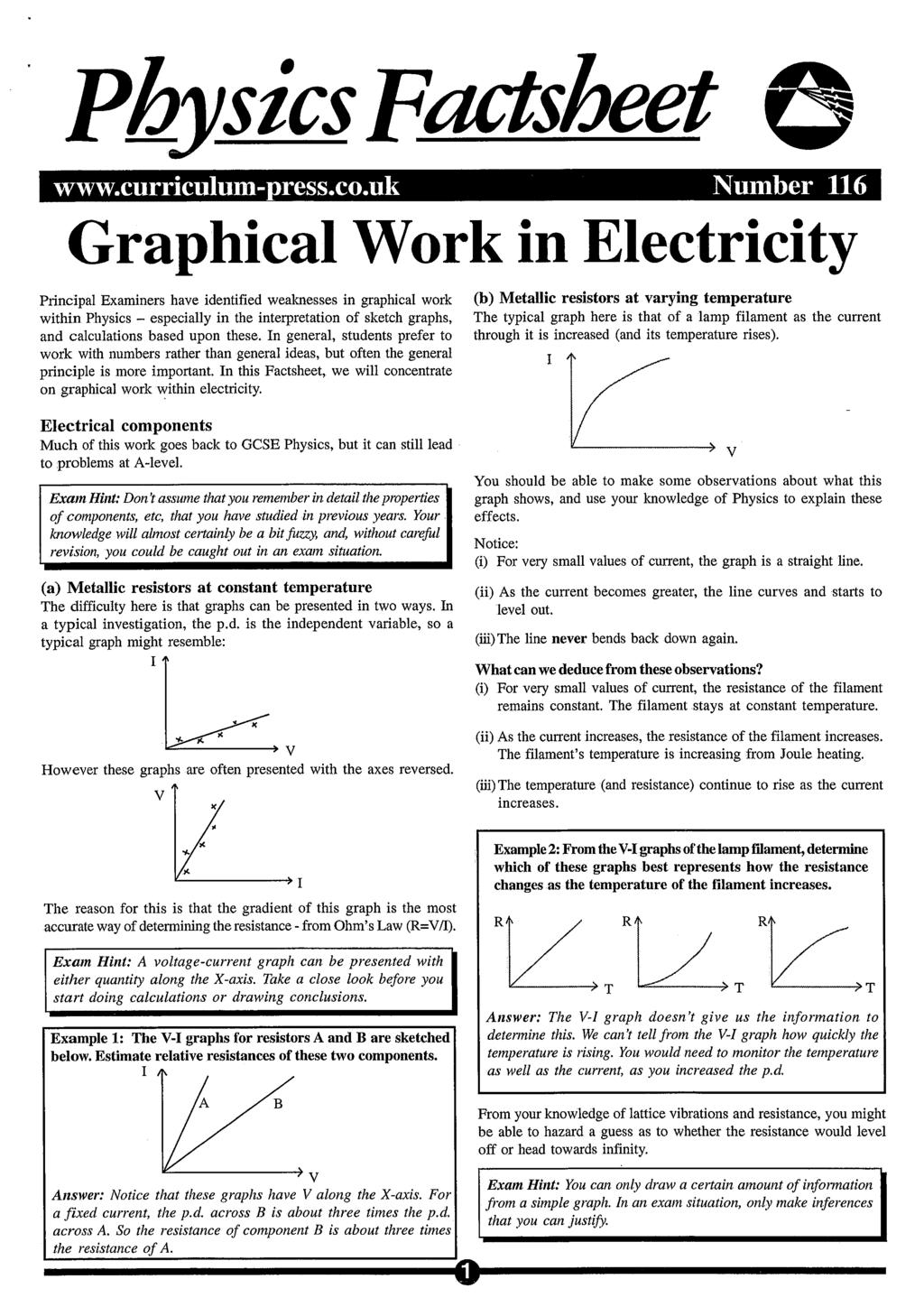
43
44
45
46 April 2001 Number 17 Waves Basics This Factsheet will introduce wave definitions and basic properties. Types of wave Waves may be mechanical (i.e. they require a medium such as air or water to propagate) or electromagnetic (which propagate in a vacuum) Waves can be classified as: a) Transverse here the disturbance is at right angles to the direction of the wave. Examples include water waves and light (electromagnetic). wave direction Wave pulses and continuous waves A wave pulse involves a short or single disturbance of the medium it is travelling in. For example, dropping an object in water may produce a wave pulse. Continuous waves involve repeated disturbances of the medium. For example, to produce continuous waves in a ripple tank, the dipper would have to be dipped into the tank at regular intervals. The rest of the Factsheet will focus on continuous waves. The wave formula v = f v = velocity (ms -1 ) = wavelength (m) f = frequency (Hz) Particles in the wave vibrate at 90 o to wave direction b) Longitudinal here the disturbance is in the same direction, parallel to the direction of the waves. Examples include sound and seismic P waves. wave direction compression expansion (rarefaction) Particles of the wave vibrate in the same direction as the wave Both longitudinal and transverse waves can be represented graphically as shown below. Exam Hint: You will be expected to know examples of longitudinal and transverse waves and to describe the differences between them. To see where this formula comes from, consider how far the wave moves in one second. We know (from the definition of frequency) that there are f waves each second. Each wave is of length. So the total distance moved in one second is f But velocity = distance time, so v = f Typical Exam Question a) What is the velocity of a wave with wavelength 25cm and frequency 12 Hz? [2] = = 3ms -1 b) A wave has a velocity of 1.25 ms -1. Eight waves are observed to pass a fixed point in 2 seconds. Find i) the period of the wave [1] 28 = 0.25 ii) the wavelength of the wave [2] f = 1/T = 4 = v/f = 1.25/4 = m. Glossary Amplitude: the maximum displacement of a wave particle from its undisturbed position. Wavelenth: the distance between two similar points on a wave. Units: metres Frequency: the number of waves that pass a point in one second. Units: Hertz (Hz) Period: the time taken to complete one wave cycle. Units: second (s) 1 The period (T) and the frequency (f) are related by T = f displacement amplitude wavelength trough peak position Peak(or crest): the point of maximum displacement the highest point Trough: the point of minimum displacement the lowest point 1
47 Waves basics Wave properties All waves will undergo the following processes according to the same laws: reflection refraction interference diffraction Reflection and its laws There are two laws of reflection. They apply to both plane (flat) and curved mirrors (or other reflecting surface for waves other than light). incident ray the incident ray and reflected ray lie in a single plane which is perpendicular to the surface at the point of incidence angle of incidence (i) is equal to angle of reflection (r) i normal (90 o to surface) r reflected ray Refractive index Consider a wave passing from material 1 to material 2. In material 1 its angle to the normal is 1 and in material 2 it is 2. incident ray From Snell s Law, we know that sin 1 = a constant sin 2 This constant is the refractive index of material 2 with respect to material 1, written 1 n 2. So Snell s Law can be written as: sin = 1 n 2 sin 1 2 normal 1 2 refracted ray material 1 material 2 NB: The angles are always measured to the normal, NOT the reflecting surface Refraction Refraction is the change in direction of a wave as it crosses the boundary between two materials (eg air and water). incident ray normal Now suppose the ray is instead travelling from material 2 to material 1. Using the above equation, we would obtain: sin 2 =2 n 1 sin 1 This gives: 2 n n 2 i r air boundary water Wave speed, wavelength and refractive index Refractive index is also related the the wave speed and wavelength in the two materials. This is used to define the refractive index. If the wave crossed the boundary in the opposite direction (i.e. water to air) then the wave direction would change in the opposite way: Refraction is governed by two laws: incident ray i r normal refracted ray water boundary air refracted ray the incident ray and reflected ray lie in a single plane which is perpendicular to the surface at the point of incidence Snell s Law : at the boundary between any two given materials, the ratio of the sine of the angle of incidence to the sine of the angle of refraction is constant for rays of any particular wavelength. 1 v n2 v 1 2 where v 1 = velocity of wave in material 1 v 2 = velocity of wave in material 2 This defines the refractive index. Also, since frequency does not change during refraction: 1 1n 2 2 where 1 = wavelength of wave in material 1 2 = wavelength of wave in material 2 The refractive index is often given relative to air. So if, for example, a question tells you that the refractive index of glass is 1.50, it means that airn glass = Exam Hint: Defining the refractive index is commonly asked. Make sure you use the equation involving wave speeds, and define all the terms. 2
48 Waves basics Typical Exam Question The refractive index of water is The speed of light in air is ms -1. a) Calculate the speed of light in water. [2] 1.33 = v v air water 310 v 8 water v water = = ms b) State the effect of the refraction on the frequency [1] none it is unchanged Tip: The speed of light in any other medium should always be lower than in vacuum (or air). Use this to check your answer if you have got too high a speed, you have probably got the v air and v material the wrong way up in the equation Interference When two sets of waves combine, we use: Principle of Superposition The resultant displacement at a point is equal to the vector sum of the individual displacements at that point. To see how this works, we will look at some examples: 1. Constructive Interference Wave 1 + Wave 2 Critical angle and total internal reflection When light travels from a material with a higher refractive index to one with a lower refractive index (eg from glass to air), it is possible for the angle of refraction to be 90 o. incident ray Produces In this case, the peaks and troughs in the two waves coincide, and hence reinforce each other. glass air i r refracted ray 2. Destructive Interference Wave 1 + normal Wave 2 The angle at which this occurs is called the critical angle, c. sin 1 sin c Using the equation = 1 n 2, we find: glassnair sin 2 sin90 But since we are usually given air n glass, not glass n air, it is more useful to write this as: sin c 1 sin90 air n glass Since sin90 o = 1, we have: 1 sin c air n glass Given that the refractive index of glass is 1.50, we can calculate: sinc = c = 41.8 o 1.50 (3 SF) Note: this cannot occur for light travelling from air to glass, since the angle to the normal decreases when travelling in this direction. What happens for angles larger than the critical angle? If the angle of incidence is greater than the critical angle, then the ray cannot be refracted instead it is totally internally reflected incident ray i reflected ray glass air In fact, a certain amount of reflection will always occur at the interface, but for angles greater than the critical angle, only reflection can occur. The incident and reflected ray obey the laws of reflection. 3 Produces In this case, the peaks in one wave coincide with the troughs in the other, to produce no resultant displacement the two cancel. 3. Wave 1 + Wave 2 Produces In this case, peaks and troughs do not exactly coincide. Phase difference Phase difference is a way of measuring how far ahead one wave is of another (eg half a wavelength, quarter of a wavelength etc). It is given as an angle, with a whole wavelength corresponding to 360 o. So if one wave leads another by a quarter of a wavelength, this is a phase difference of ¼ 360 o = 90 o. If the phase difference is zero (example 1 above), they are in phase. If the phase difference is 180 o (= half a wavelength), they are completely out of phase (example 2).
49 Waves basics Sources of waves are coherent if they maintain a constant phase difference and have the same frequency (eg lasers). A wavefront is a line or surface in the path of a wave motion on which all the disturbances are in phase. It is perpendicular to the direction travel of the wave. Diffraction of light and the single slit Diffraction of light through a slit onto a screen leads to the production of light and dark fringes. The brightness and width of the fringes can be represented graphically: Typical Exam Question a) Explain what is meant by superposition of waves. [2] Waves coinciding at a point in space Disturbances add together, i.e. superpose b) Distinguish between constructive and destructive interference. [4] Constructive: waves in phase as they superpose Disturbances add to give a larger amplitude Destructive: waves 180 o out of phase Disturbances cancel to give zero amplitude c) State the conditions necessary for sources of waves to be coherent.[2] Same frequency Constant phase relationship Diffraction When waves pass an edge of an obstacle, or through a gap, they spread out and change shape. The wavelength, frequency and velocity remains constant. The extent of the spreading depends on the size of the gap, as shown below: brightness central fringe The fringe pattern has the following properties: It is symmetrical The central bright fringe is much brighter than the other fringes It is twice as wide as the other fringes The brightness (intensity of light) decreases with distance from the central fringe so the outer fringes are the faintest. The position of the dark fringes can be calculated using: sin = w a where = angle subtended in the centre (see diagram) = wavelength w = slit width a = 1, 2, 3. (fringe number) Central light fringe 1 st dark fringe 2 nd light fringe 2 nd dark fringe Double slit diffraction This produces a difference in intensity within each bright fringe seen in the single slit pattern. This results from interference between light from one slit the other original one-slit fringe Exam Hint: When drawing diagrams of diffraction, make sure you keep the spacing between the wavefronts the same this shows the frequency of the waves is unchanged. Appreciable diffraction only occurs if the gap is no bigger than the wavelength of the wave. Variation in intensity due to two slits The narrower the slit, the greater the diffraction for a particular wavelength The longer the wavelength for a constant slit width, the greater the diffraction This interference results from the fact that light from the different slits travels a different distance to reach a given point on the screen; this is referred to as the path difference. 4
50 Waves basics At the centre of the screen (point A), waves from slits X and Y have travelled the same distance and therefore are in phase, and hence interfere constructively leading to a bright fringe. Progressive and stationary waves The waves discussed so far have been progressive i.e. they move in a particular direction, transferring energy along the direction the wave is travelling. In a stationary (or standing) wave, the wave does not move in a particular direction and energy is stored by the wave. slits Y X A screen Stationary waves are the result of two progressive waves of the same frequency travelling in opposite directions along the same line. The diagram below shows an example of a stationary wave. B Each point on the wire can oscillate between the two positions shown. As the distance from the centre changes, so does the path difference between the waves from each slit. At point B, for example, the waves from slit Y have travelled substantially further than those from slit X. N Oscillates between these points N N When the path difference becomes half the wavelength, then destructive interference occurs, producing a dark fringe. Further increases in distance from the screen increases the path difference until it becomes a whole wavelength this makes the waves in phase again, so constructive interference occurs. Further increases produce a path difference of 1½ wavelengths giving destructive interference again. So the bright fringes are produced from path difference m, and the dark fringes from path difference (m + ½), where is the wavelength and m is any whole number. The fringe spacing between two adjacent bright fringes is given by D y = d D = distance to screen; = wavelength; d = slit spacing In between the light and dark fringes, the interference is not perfectly constructive or destructive, so the intensity of the light changes gradually. Polarisation Normally, the oscillations in a transverse wave may be in many different directions. For example, for a wave travelling out of this page towards you, the oscillations will be in the plane of the page, and could be left to right, up and down, diagonally etc. Transverse waves may undergo polarisation. A polarised wave oscillates in one direction only. Longitudinal waves cannot be polarised because the oscillations are already in one direction only. Exam Hint: This is a key difference between longitudinal and transverse waves, and is often asked. Polarised light is most easily produced using a piece of Polaroid (as used in sunglasses). Polaroid works by only allowing through light which oscillates in a particular direction A The nodes (marked N) never move. These occur where the two original waves interfere destructively The antinodes (marked A) are points of maximum displacement. They occur where the two original waves interfere constructively. Table 1 below compares progressive and stationary waves. Table 1. Progressive and stationary waves Stationary wave Progressive wave Stores vibrational energy Transmits vibrational energy Amplitude varies Amplitude is constant All points between any two adjacent nodes are in phase Phase varies smoothly with distance along the path of the Nodes are half a wavelength apart; antinodes are midway between nodes Typical Exam Question a) Explain the terms node and antinode [2] Node: point of no vibration Antinode: point of maximum vibration wave No nodes or antinodes b) Two identical progressive waves are travelling along the same straight line in opposite directions. (i) Explain how a stationary wave pattern is formed [3] Stationary wave is formed by the superposition of the two waves Nodes are created by destructive interference and antinodes are created by constructive interference. (ii) Compare the amplitude and phase of particles along a stationary wave with those of a progressive wave. [2] All points on a stationary wave are in phase, points on a progressive wave are out of phase with each other All points on a progressive wave have the same amplitude, different points on stationary wave have different amplitudes A If the light is passed through a vertical piece of Polaroid, then the emerging ray will be polarised vertically. It will have half the intensity of the original beam this is why sunglasses work. If this ray then meets a horizontal piece of Polaroid, no light will pass through. 5
51 Waves basics Exam Workshop This is a typical poor student s answer to an exam question. The comments explain what is wrong with the answers and how they can be improved. The examiner s answer is given below. a) (i) Explain the term 'wave front' [1] it s at right-angles to the wave direction 0/1 (ii) This statement is true, but does not explain wavefront. When the student read the next part of the question, s/he should have realised that this was not an adequate answer. State the relationship between the orientation of a wave front and the direction in which the wave is travelling [1] at right angles 1/1 b) A longitudinal wave of frequency 30 khz has a speed of 340ms -1 when travelling in air. Its wavelength when travelling in water is 0.05m. (i) Calculate the minimum distance between two points on the wave that differ in phase by 60 o when it is travelling through air.[3] 60 o = one sixth of wavelength = 0.008m 1/3 The first part of the method is correct, but the student has used the wavelength for water waves. Read the question! This shows the advantage of showing working without it, no marks would have been awarded. (ii) Calculate the speed of the wave in water [2] 1.5ms -1 0/2 The student has probably failed to convert khz to Hz. If s/he had shown working, one mark might have been awarded, since s/he could have demonstrated the knowledge that frequency is unchanged. The answer should have worried him/her! (iii) A pulse of the wave lasts for 10ms. Calculate the number of complete waves that it contains. [2] = 300 2/2 The student has evidently now realised that the frequency is 30 khz, not 30 Hz, but has neglected to change the earlier answer! Always make time to check. Examiner s Answers a) (i) A surface in which all oscillations are in phase (ii) They are perpendicular b) (i) = v/f =340/30000 =0.0113m Phase difference of corresponds to /6 = 1.89mm (ii) speed in water = f wavelength in water = =1500ms -1 (iii) Number of waves = time of pulse frequency = =300 Questions 1. a) Explain the difference between transverse and longitudinal waves. b) Give two examples of transverse waves and two examples of longitudinal waves. 2. Explain the difference between a wave pulse and a continuous wave. 3. Explain what is meant by the following terms: Amplitude Wavelength Peak Trough Frequency 4. Define the refractive index for a wave travelling from material 1 to material Explain what is meant by the Principle of Superposition. 6. Explain what is meant by diffraction. 7. Explain why sound waves cannot be polarised. 8. Give two differences between a stationary wave and a progressive wave. 9. A wave has speed 50ms -1 and wavelength 2m. Calculate its period. 10. The refractive index of glass is a) A ray of light passes from air to glass. It makes an angle of 20 o to the normal just before entering the glass. Calculate the angle the refracted ray makes with the normal. b) The speed of light in air is ms -1. Calculate the speed of light in glass. c) Calculate the critical angle for glass. Answers 1. See page 1 2. See page 1 3. See page 1 4. See page 2 5. See page 2 6. See page 4 7. See page 5 8. See page 5 9. f = 50/2 = 25Hz T = 1/f = 0.04 s 10. a) sin20/sinr = 1.5 sinr = sin20/1.5 = r = 13 o b) c air / c glass = 1.50 c glass = / 1.50 = ms -1 c) sinc = 1/1.5 = c = 42 o (2 SF) Acknowledgements: This Factsheet was researched and written by Nirinder Hunjan Curriculum Press, Unit 305B The Big Peg, 120 Vyse Street, Birmingham B18 6NF. Physics Factsheets may be copied free of charge by teaching staff or students, provided that their school is a registered subscriber. They may be networked for use within the school. No part of these Factsheets may be reproduced, stored in a retrieval system or transmitted in any other form or by any other means without the prior permission of the publisher. ISSN

52
53
54
 What is interference? When two waves of a similar type meet they interfere with each other.")
55 PhysicsFactsheet January 2003 Number 47 Interference This Factsheet will expain: what is meant by interference interference patterns double slit interference Before working through this Factsheet you should make sure you understand the basic ideas in waves (Factsheet 17) What is interference? When two waves of a similar type meet they interfere with each other. The intensity at that point is the sum of the intensities of the two waves at that point. This is called the principle of superposition of waves. It works for all types of waves and for two waves or more. At every position in front of the speakers, waves are arriving from both sources. In some places the waves will be in phase with one another; that is, the peaks of both waves arrive at exactly the same point at the same time. In these places, the principle of superposition predicts that the resultant wave has double the amplitude and you would hear a louder sound. This is called constructive interference each wave interferes with (or is superposed upon) the other to produce a bigger wave. However, there will be other points nearby where the peak of the wave arriving from one speaker coincides exactly with the trough of the wave arriving from the other speaker. If the two waves are of equal amplitude at this point, then they interfere with one another to produce a wave of zero amplitude cancelling one another out. At this point you would expect to hear absolute silence! (In practice, echoes from the surrounding surfaces mean it is unlikely it would actually be silent but the sound heard at this point would certainly be much quieter.) This is known as destructive interference and is the more surprising effect of the principle of superposition. Remember that it is not quiet at this position because no wave is arriving but because TWO waves are arriving, out of phase, and each one is cancelling out the other. If one of the speakers were to be turned off, the sound at this point would get louder. Two waves out of phase interfere to cancel one another out Two waves in phase interfere to produce a bigger wave Adding waves of different wavelengths and amplitudes results in complex waveforms. However, there are some interesting effects when two waves with the same wavelength overlap. Constructive and destructive interference Imagine, for example, a situation where the same pure musical note is fed to two loudspeakers a short distance apart and facing in the same direction. You might expect that the sound you would hear in front of the speakers would be louder than if there were only one speaker. To a certain extent this is true but it is only part of the story. If you move around in the area in front of the speakers then you would notice that in some places the sound is louder, in others it is quieter. These are interference effects. The diagram shows what is happening. The positions of the loudspeakers are labelled 1 and 2 and the diagram shows where maxima (positions where the sound is loudest) and minima (positions where the sound is quietest) occur. Constructive interference occurs when two waves are in phase - their peaks coincide amplitude of resulting wave is sum of original amplitudes Destructive interference occurs when two waves are totally out of phase/phase difference of 180 o = π radians) amplitude of resulting wave is the difference of original amplitudes - which will be zero if the original waves had the same amplitude Interference occurs for all types of wave so it is possible to observe exactly the same effect with two light sources as long as they are both coherent and of similar amplitudes. (Coherent waves have the same frequency and a constant phase relationship.) In this case, the effect of constructive interference would be brighter light and the effect of destructive interference would be no light or darkness. It is even harder to believe that an area is in darkness because two lights are shining on it simultaneously but just because something is surprising doesn t make it untrue! In this case, switching or blocking one of the light sources off would make it light again at that point! loudspeaker1 loudspeaker 2 maximum minimum central maximum minimum maximum Interference patterns of this kind in microwaves are the reason that the food in a microwave oven is placed on a rotating turntable. If it were kept still, there would be hot spots and cold spots in the food in most foodstuffs, the conduction is too slow to spread the heat around evenly in the cooking time. In radio waves, interference patterns are set up when the same signal is simultaneously transmitted from two aerials at a distance apart. If you had a moveable receiver (such as a car radio) and were tuned into this frequency as you travelled across the region where both of these signals overlapped, then you would experience the received signal getting weaker and stronger and the radio getting quieter and louder - as you moved through the interference pattern. 1
56 Interference Physics Factsheet Demonstrating intereference patterns The effect can be clearly demonstrated in a ripple tank. Two coherent wave sources are produced by attaching two dippers to a single beam suspended by rubber bands above the water in the ripple tank. The beam is vibrated by a motor with an eccentric mass (i.e. a mass which is not mounted at its centre) so that it wobbles as the motor spins. The height is adjusted so that both dippers touch the surface of the water producing coherent waves from points several centimeters apart. The resulting wave pattern is shown in the photograph below. The pattern of constructive and destructive interference, as waves coincide in phase in some places and out of phase in others, produces bands of interference that appear to fan out from the space between the sources. There will be further bright fringes at each position on the screen where the path difference is exactly equal to two wavelengths, three wavelengths and so on. The bright fringes will appear to be equally spaced on the screen. In between these bright fringes will be dark fringes of destructive interference. At each of these positions, the path difference will be exactly equal to ½ a wavelength, 1½ wavelengths, 2½ wavelengths and so on making the waves exactly 180 o out of phase. The equation: λ = ax describes this relationship D where: λ = wavelength a = separation of the slits (distance between the centres of the two slits) x = distance between successive fringes D = distance from the slits to the screen (all measurements in metres) Double slit interference To demonstrate the same effect as described above using light waves requires a little more sophistication. In practice, the only way to ensure two coherent wave sources is to use a single light source of just one wavelength best achieved by using a laser and to split that using an arrangement known as Young s slits (after Thomas Young, who designed this experiment in 1801 to measure the wavelength of light). This is a slide with two narrow, parallel slits very close together. The laser beam falls onto both slits and passes through each, spreading out slightly by diffraction as it does so. The light waves emerging from each slit act as two separate beams of light and (since they come from the same source) these two waves have the same wavelength and leave the slits in phase with one another they are coherent. A screen is placed some distance from the laser (usually several metres away so the room needs to be dark if they are to be seen clearly) and interference bands (or fringes) can be seen. They appear as alternate areas of light and darkness, where the two waves interfere with one another constructively and destructively. The diagram below shows the relationship between the various quantities in this arrangement. Questions 1. (a) Explain what is meant by superposition of waves. [2] (b) Distinguish between constructive and destructive interference. [4] (c) State two conditions necessary for sources of waves to be coherent. [2] (d) Why is it necessary to have two coherent sources to produce an interference pattern. [2] 2 (a) A student sets up two loudspeakers to perform an experiment on the interference of sound. The loudspeakers produce sound waves with the same frequency, which is known to be below 1kHz. She finds a point of destructive interference, i.e. a point where the noise level is very low, at 3m from one speaker and 2m from the other. Determine all possible frequencies at which the speakers could have been oscillating. Take the speed of sound in air as 340ms -1. [4] (b) She now stands midway between a different pair of speakers, which are oscillating at 400 Hz, and 401Hz respectively. The sound waves produced by these speakers have equal amplitudes. Describe and explain what she hears. [4] 3. Microwaves with a wavelength of 6cm are directed towards a metal plate. The plate is 20cm wide and has two parallel slits in it. An interference pattern is formed on the far side of the plate. nλ (n+1)λ x laser a s 1 20 cm s 2 D emitter 30 cm Detector screen Where the two waves have travelled the same distance from both slits to the screen (i.e. right in the middle of the interference pattern) then they will be in phase and there will be a bright fringe this central maximum is the brightest of all the fringes. Moving to either side of the central fringe, there will be another bright fringe at the point where the wave from one of the slits is once again in phase with the wave from the other slit. This occurs when the wave from the further of the two slits has travelled exactly one wavelength more than the other we say that the path difference is equal to one wavelength. 2 (a) A microwave detector is placed 30 cm directly in front of one of the slits. The detector gives a zero reading. (i) Comment on the phase difference between the waves from each slit at this point and use this to explain why the detector gave a reading of zero. [2] (ii) Calculate the distance between the two slits. [4] (b) What would happen to the interference pattern if the plate were rotated through an angle of 90 o? Explain your answer. [3]
57 Interference Physics Factsheet Answers 1. (a) Waves coinciding at a point in space! Disturbances add together, i.e. superpose! (or diagram) (b) Constructive: waves in phase as they superpose! Disturbances add to give a larger amplitude! Destructive: waves 180 o out of phase! Disturbances cancel to give zero amplitude! (or diagram) (c) Coherent sources have: Same frequency! Constant phase relationship! (d) Without coherent sources the phase relationship between the waves would be continuously changing! No steady interference pattern.! 2. (a) Destructive interference or cancellation implies the path difference is an odd number of half wavelengths, i.e. λ/2, 3λ/2, 5λ/2, 7λ /2 etc! The path difference = 1m Hence: λ = 2m, 2/3m, 2/5m, 2/7m, etc.! Using f = v/λ gives the following possible frequencies: 170Hz, 510Hz, 850Hz, 1190Hz, etc.! As we know that the speakers were oscillating below 1kHz, the only possible frequencies for the sound are: 170Hz, 510Hz, 850Hz! (b) The student will hear a periodic variation in the loudness of the sound ( beats )! The phase difference between the two waves constantly, and periodically changes due to the slight difference in frequency! When the waves are in phase they will reinforce each other, increasing the loudness of the sound. As the two waves move into anti-phase they cancel each other and the loudness of the sound decreases! The frequency of the beating effect will be: = 1Hz! 3. (a) (i) The waves from the two slits must be in anti-phase at this point! i.e. phase difference of π radians. Giving destructive interference! (ii) The path difference from each of the slits must be an odd number of half wavelengths! A B 30 cm L path difference = L-30 Smallest possible path difference = λ/2 = 3cm! Then AB 2 = , AB = 13.75cm! The next possible path difference, 3 λ/2 gives AB = 25cm which is greater than the width of the plate! (b) The pattern would vanish! Microwaves are transverse and polarised! With the plate turned through 90 o, the microwaves cannot pass through the slits! Exam Workshop This is a typical weak student s answer to an exam question. The comments explain what is wrong with the answers and how they can be improved. The examiners mark scheme is given below. A pair of parallel slits are illuminated with light from a sodium vapour lamp of frequency Hz. A series of light and dark fringes is projected on to a screen 1m from the slits. (a) Explain why a bright fringe is always found at the centre of the pattern. [3] There is constructive interference 1/3 The student has demonstrated that s/he knows what fringes are caused by, but has failed to explain why it occurs at the centre. S/he should have realised that this was not adequate for 3 marks (b) The distance between the central bright fringe and the adjacent bright fringe is 1mm. How far apart are the slits? ( c = ms -1 ) [4] λ = ax! D λ = a 1 = a 1 fλ = c a = c!ecf = = /4 f The student has not changed 1 mm into 10-3 m when using the formula. The rest of the working is correct, but the answer should be given to 3 significant figures Examiner s answers (a) At the centre of the pattern, waves from each slit have travelled equal distances.i.e. path difference is zero! This implies that the phase difference is zero! Thus constructive interference will always occur at the centre of the pattern, producing a bright fringe! (b) wavelength λ = c = f = m! λ = ax D Let x = distance between the bright fringes a = distance between slits D = distance between slits and screen a = λd x! a = ( ) a = m!! Acknowledgements: This Physics Factsheet was researched and written by Keith Penn. The Curriculum Press,Unit 305B, The Big Peg,120 Vyse Street, Birmingham, B18 6NF. Physics Factsheets may be copied free of charge by teaching staff or students, provided that their school is a registered subscriber. No part of these Factsheets may be reproduced, stored in a retrieval system, or transmitted, in any other form or by any other means, without the prior permission of the publisher. ISSN
58
59
60
61
62
63
64
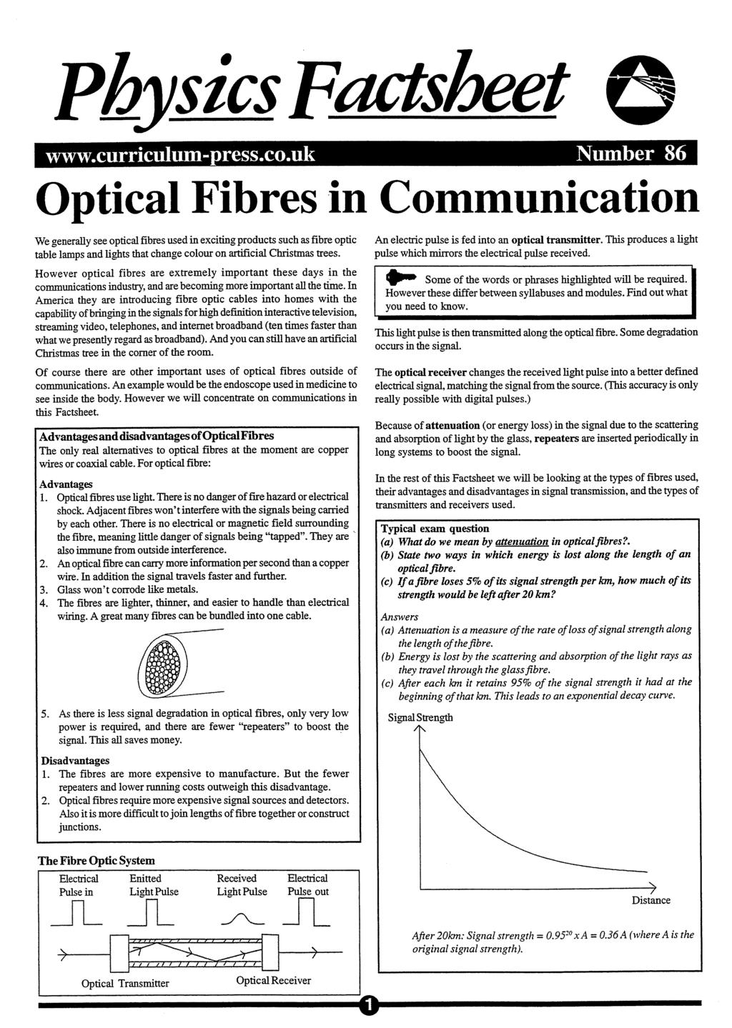
65
66

67
68

69
70
71
72
73
74

75
76
77 PhysicsFactsheet Number 69 Experiments With Waves A ripple tank is a simple and common way of demonstrating properties of waves, including reflection, refraction, diffraction and interference. The tank is shallow with sloping sides (to cut down on reflection when waves hit the sides) and with a transparent bottom so that a light source can be mounted below the tank, projecting a magnified image of the water waves onto a screen (usually the ceiling) above. Diffraction at a narrow gap a wide gap The movement of the waves can be stopped for certain observations and measurements using a stroboscope either a simple hand wheel with regularly spaced slits or an electronic stroboscope in place of the projection lamp. The stroboscope doesn t actually stop the wave movement, of course it gives a series of snapshot views of the wave timed at such a frequency that each snapshot is exactly one wave period after the previous one. This means that the viewer sees each wave crest in exactly the same position as the preceding wave making it appear to be standing still. (Running the stroboscope slightly slower or slightly faster can give the appearance of slow forward or reverse movement of the waves a fact well-known to cinema-goers used to seeing wagon wheels appear to spin backwards as the stagecoach slows down and the wheel movement strobes with the frame frequency of the cine camera.) Waves are usually generated by a small electric motor mounted on a wooden bar. The bar hangs by two rubber bands from a stable cross frame above one end of the tank. The motor has a weight attached to the axle, but the weight is mounted eccentrically (i.e. off-centre) so that it wobbles as it spins and so, therefore, does the wooden bar. The bar can be lowered so that it touches the surface of the water in the tank causing parallel plane waves to be generated at the frequency of rotation of the motor. Alternatively, one or more small plastic dippers in the shape of small balls can be fixed into holes in the bar and the height adjusted so that the dipper(s) just touch the surface. This produces a point source of waves which spread out as a series of concentric circles. A range of accessories may then be placed in the path of the waves to demonstrate the various properties of waves. Reflection from a plane reflector Refraction or a curved reflector Interference 1 2 maximum minimum central maximum minimum maximum The ripple tank demonstrates wave properties in water waves which have wavelengths large enough to be seen clearly. However, once the effects of wave properties have been understood, those effects can be recognised, observed and investigated using other types of waves even when the wavelengths involved are either too large or too small for the individual waves to be seen. Wave properties in light waves - using a laser A laser produces a convenient narrow, strong, sharply focussed beam of light and so in reflection and refraction experiments it can replace the simple ray which uses a low voltage electric lamp. However, the laser really comes into its own when used in diffraction and interference experiments. Safety note: The typical popular (science fiction) understanding of a laser is that it will cut through a sheet of metal. Although such lasers exist, you will be pleased or disappointed to find that the one you will use does not produce anything like this sort of power. It is, however, powerful enough to do serious and permanent damage to the retina of the eye if you look directly into the beam. Don t try it and make sure the experimental set-up doesn t allow anybody else to try it either, intentionally or otherwise! If the beam reflects off a highly reflective surface (like a mirror or glass window) it can be just as dangerous. 1 For interference between two wave sources to be observed, those sources need to be coherent. Two waves are said to be coherent when they have the same wavelength and frequency and a constant phase relationship to one another.

78 69 Experiments with Waves Physics Factsheet The phase relationship refers to the relative position of peaks and troughs of two waves. If the peaks of both waves occur at the same position, then the waves are said to be in phase. If the peaks of one wave coincide with the troughs of the other, then they are exactly out of phase, or 180 out of phase out of phase in phase Stationary waves experiments Stationary waves offer a number of interesting experimental possibilities. They enable certain key measurements to be taken with a degree of accuracy difficult or impossible when dealing with travelling waves. A stationary wave can arise when a wave travelling in one direction along, or through, a particular medium, interferes with a second wave, similar in every respect to the first but travelling in the opposite direction. In practice, the second wave is often in fact the first wave returning after reflection from an end or fixed point of the wave guide or wave medium. The stationary wave has fixed nodes positions of zero amplitude and antinodes positions of maximum amplitude. Often, we have a situation where only certain clearly defined frequencies can exist in a stationary wave. Example a vibrating string, fixed at both ends (like a guitar string) Producing two coherent sources of water waves is not too difficult using the ripple tank arrangement described above, the wooden bar simply has two plastic dippers placed in it, both touching the surface of the water. When the motor wobbles, so does the bar and so do the dippers all together. Producing two coherent sound waves is not too difficult either just connect two loudspeakers to the same amplifier output (i.e. mono, not stereo!). However, two coherent light sources are a different problem altogether. An ordinary light bulb of the type used in a laboratory ray box emits a wide range of light frequencies. Even passing the light through a colour filter still leaves a range of frequencies too wide for interference effects to be seen. The effect of interference at one frequency is alongside the same effect for a slightly different frequency and each effect would be masked by all of the others. To make a comparison with sound waves, the light bulb is like hitting all the notes on a piano at the same time producing a noisy chord (or discord!) of lots of different frequencies all at once. To hear clear sound effects, it is necessary to pick out a single frequency like a single note on the piano, or better still a tuning fork. The laser is rather like a tuning fork for light waves it emits a very pure, narrow frequency of light. Even so, buying two similar lasers and putting them alongside one another would not guarantee coherent waves. A simple but clever trick is to shine one laser beam through two narrow, parallel slits, usually mounted in a projector slide (the arrangement is known as Young s slits, named after the inventor). The light waves diffract (spread out slightly) as they pass through the slits and become two beams and, since they have come from the same single source, they must be coherent. The coherent waves are projected onto a screen several metres away from laser a s 1 s 2 the laser which could be the opposite wall and maxima and minima are observed as clear patches of bright light and darkness. These represent the positions where the waves are exactly in phase or exactly out of phase respectively just as seen with the ripple tank interference experiment above. This equation describes the relationship between the various measurements which may now be taken, where: D The equation: λ = ax describes this relationship D where: λ = wavelength a = separation of the slits (m) (distance between the centres of the two slits) x = distance between successive fringes D = distance from the slits to the screen (m) nλ (n+1)λ screen x 2 fundamental frequency first harmonic second harmonic A simple experimental way to investigate standing waves with two fixed ends is to set up a stretched cord between two fixed points several metres apart. This can be thin rubber cord, square or circular in cross-section and of about 5mm diameter fixed to two rigid supports (which might be clamp stands clamped tightly, to the benchtop); or it might be thin string, in which case at least one end needs to run over a pulley and then be loaded with a small mass the mass may then be adjusted to change the tension in the string, one of the factors affecting the fundamental frequency of vibration. Close to one of its ends, the string needs to pass through the top of a vibration generator which is driven by a signal generator producing a sine wave output of variable frequency. The string will resonate (vibrate with large amplitude as shown in the diagram showing fundamental frequency) when the driving frequency is equal to the fundamental frequency of the string set-up. In this condition, the stationary wave has only two nodes the two ends of the string and one central antinode. The wavelength is easily calculated, since the full length of the string is exactly equal to half of one wavelength. The frequency of the vibrations may be measured by feeding the output of the signal generator into an oscilloscope or a frequency meter; or by the use of a calibrated stroboscope. (The flash rate of the stroboscope is increased slowly until the vibrations appear to stand still.) The wave equation (speed = frequency wavelength) may be used to calculate the speed of wave travel along the string. A number of investigations are possible with this set-up, by changing the tension in the string, or the mass per unit length of the string, or the length of the string. Doubling the driving frequency will produce a stationary wave of the first harmonic as shown in the diagram above the full length of the string now corresponds to one full wavelength. (This corresponds to playing a note one octave higher than the fundamental on a musical string instrument.) Three times the frequency gives the second harmonic with three half-wavelengths fitting into the length of the string, and so on. It is relatively easy to get up to the tenth or even the fifteenth harmonic with a light string or elastic cord. Experiment with different coloured backgrounds and lighting to see the stationary waves most clearly it is sometimes easier to see the wave pattern whilst looking along the string from one end.
79 69 Experiments with Waves Physics Factsheet Measuring the speed of sound The speed of sound may be measured by setting up a small region of stationary sound waves inside the laboratory. Sound is produced by a signal generator driving a loudspeaker at a fairly high audible frequency, say 3000Hz. A wooden board or convenient wall about 1.5m from the loudspeaker is used to reflect (echo) the sound waves back. A standing wave pattern now exists between the loudspeaker and the reflecting surface. A microphone is mounted in a clamp stand so that it can be moved and rested in positions between the loudspeaker and the reflector. An oscilloscope is used to display the output from the microphone. If the microphone is slowly moved towards the loudspeaker it will be noticed that the amplitude of received sound goes through maxima and minima of amplitude. (It is worth pushing the clamp stand holding the microphone with a metre rule to cut down on reflection of sound from your arm and body.) The distance between successive maxima is one half-wavelength. (Moving the microphone through about ten successive maxima and dividing that distance to find one wavelength can reduce the error.) Frequency of the sound waves can be measured directly from the oscilloscope. The wave equation may now be used to calculate the speed of the sound waves. Resonance in air columns Stationary waves in air columns (such as organ pipes or other wind instruments) differ from those set up in stretched strings because different sets of harmonics are allowed by the physical constraints of the medium. This is the main reason why a particular note played on a string instrument sounds different from the same note played on a wind instrument the fundamental frequency is the same but the pattern of harmonics which overlay that note (at lower amplitudes) are different. This pattern of harmonics is known as the quality or sometimes the timbre of the note. A hollow cylinder containing a column of vibrating air is normally closed at one end and open at the other so, whilst one end (the closed end) corresponds to a node of the stationary wave pattern, the open end corresponds to an antinode. This means that the lowest (fundamental) frequency allowed is when one quarter of a wavelength is contained within the air column. The first harmonic is when three-quarters of a wavelength is equal to the length of the air column, and subsequent harmonics correspond to five-quarter wavelengths, seven-quarter wavelengths and so on. In a wind instrument, the air column is normally set vibrating by resonance from a small oscillator at one end which may be a reed (as in some woodwind instruments) or even the musician s lips (brass instruments). This may be modelled by a tuning fork, or a small loudspeaker driven by a signal generator, placed at the open mouth of the air column. One way to set up the air column with variable length is to have two lengths of glass tubing, one of which fits inside the other. The wide-bore tube is mounted vertically (supported by a clamp) and the bottom end plugged with a rubber bung or cork. The tube is then filled not quite to the top with water. The narrower tubing is then lowered inside the water-filled tube and the top end held with a clamp and clamp stand. The air column to be used is then inside the narrow tube the bottom surface being the surface of the water. The length of the air column can now be easily adjusted by simply adjusting the height of the narrow tube and re-clamping. A metre rule may be mounted outside the tubing for easy measurement of the air column length. The tuning fork or loudspeaker is placed at the top (open) mouth of the air column and the length of the column adjusted until the sound gets noticeably louder this means that the air column is resonating. Alternatively, the air column may be left at the same length and the frequency of sound from the loudspeaker changed until resonance occurs. Once again, a variety of investigations are possible with the arrangement. Microwave experiments Most laboratory microwave transmitters and receivers work at a wavelength of around 3cm which is a very convenient and measurable size for many experiments. 3 Receivers usually come in two forms one with a directional collector (rather like a square funnel) and a probe type which is good for finding the strength of a signal at a point. Both types of receiver usually have an output which can be connected to a sensitive microammeter so that relative signal strength can be measured. The transmitter and receiver arrangement can be used for many kinds of wave experiment including investigation of reflection (microwaves will reflect well off a metal sheet), refraction, diffraction and interference. The convenient wavelength of the microwaves usually means that measurements of suitable accuracy may be made with simple apparatus such as a metre rule. Apparatus suitable for diffracting and refracting microwaves are usually available from the supplier of the 3cm wave transmitting and receiving equipment. Practice Quetions 1. A pair of parallel slits are illuminated with light from a sodium vapour lamp of frequency Hz. A series of light and dark fringes is projected on to a screen 1m from the slits. (a) Explain why a bright fringe is always found at the centre of the pattern [3] (b) The distance between the central bright fringe and the adjacent bright fringe is 1mm. How far apart are the slits? ( c = ms -1 ) [4] 2. (a) Waves from two sources can only combine to form a stable interference pattern if they are coherent. What does coherent mean? [2] (b) A student sets up two loudspeakers to perform an experiment on the interference of sound. The loudspeakers produce sound waves with the same frequency, which is known to be below 1kHz. She finds a point of annulment, i.e. a point where the noise level is very low, at 3m from one speaker and 2m from the other. Determine all possible frequencies at which the speakers could have been oscillating. Take the speed of sound in air as 340ms -1 [4] 3. Microwaves with a wavelength of 6cm are directed towards a metal plate. The plate is 20cm wide and has two parallel slits in it. An interference pattern is formed on the far side of the plate. emitter 20 cm 30 cm Detector (a) A microwave detector is placed 30cm directly in front of one of the slits. The detector gives a zero reading. (i) Comment on the phase difference between the waves from each slit at this point and hence explain why the detector gave a reading of zero [2] (ii) Calculate the distance between the slits [4] (b) What would happen to the interference pattern if the plate was rotated through an angle of 90 0? Explain your answer [3] 4. (a) Explain the difference in terms of energy, between progressive (travelling) and stationary (standing) waves [2] (b) The velocity v of a transverse wave on a stretched string is given in the formula: v 2 = T µ where T is the tension in the string and µ is the mass per unit length. Use this equation to derive an expression for the fundamental frequency of a vibrating wire in terms of T, µ and its length, L[2] (c) A violin string is 35 cm long and has a mass of 2.25 g. It produces a note of frequency 256 Hz when sounding its first overtone. Find the tension in the string [4]
80 69 Experiments with Waves Physics Factsheet Exam Workshop This is a typical weak student s answer to an exam question. The comments explain what is wrong with the answers and how they can be improved. The examiners mark scheme is given below. The equipment shown in the diagram is set up for an experiment. loudspeaker signal generator microphone CRO (a) The CRO displays two traces: one directly from the signal fed to the loudspeaker, the other from the microphone. (i) Draw a labelled diagram of a typical display you would expect to see on the CRO [3] Correct! but the student hasn't labelled the diagram a common mistake! (ii) State two aspects of this display that would change as the distance between the loudspeaker and microphone is increased [2] the phase difference between the waves increases the amplitude of microphone signal decreases 2/2 2/3 Answers 1. (a) At the centre of the pattern, waves from each slit have travelled equal distances. i.e. path difference is zero! This implies that the phase difference is zero! Thus constructive interference will always occur at the centre of the pattern, producing a bright fringe! [3] (b) c 3 10 λ = = 8 = m! f Let y = distance between the bright fringes d = distance between slits D = distance between slits and screen m = order of the fringe counting outwards from the central bright fringe y = mλd d When m =1, d = λd! y d = -7 1! d = m! [4] 2. (a) Waves from two sources are coherent if: Their frequencies are equal! The phase difference between them is constant! [2] (b) Annulment or cancellation implies the path difference is an odd number of half wavelengths, i.e. λ/2, 3λ/2, 5λ/2, 7λ/2, etc.;! The path difference = 1m Hence: λ = 2m, 2/3m, 2/5m, 2/7m, etc.! Using f = v/λ, gives the following possible frequencies: 170Hz, 510Hz, 850Hz, 1190Hz, etc.! As we know that the speakers were oscillating below 1kHz, the only possible frequencies for the sound are: 170Hz, 510Hz, 850Hz! [4] 3. (a) (i) The waves from the two slits must be in anti-phase at this point! i.e. phase difference of π radians, giving destructive interference! [2] (ii) The path difference from each of the slits must be an odd number of half wavelengths! Correct - 2 marks (b) Explain how the CRO measurements can be used to find the wavelength of the sound [5] A B 30 cm L path difference = L-30 Gradually move microphone away for the speaker Each time traces are in phase the microphone has moved one wavelength. Count the number of wavelengths moved. Measure distance moved and calculate wavelength 4/5 Correct method, but the student did not state that the traces must be in phase before the microphone is moved Examiner s answers (a) (i) Two traces drawn, out of phase!! Labels shown! phase difference (ii) Phase difference increases! Amplitude of microphone signal decreases! signal generator microphone (b) Place microphone so traces are in phase! Gradually move microphone away! Each time traces are back in phase, microphone has moved one wavelength! Count the number of wavelengths moved! Measure distance moved and calculate wavelength! Acknowledgements: This Physics Factsheet was researched and written by Keith Penn. The Curriculum Press, Bank House, 105 King Street, Wellington, Shropshire, TF1 1NU 4 Smallest possible path difference = λ/2 = 3cm! Then AB 2 = , AB = 13.75cm! The next possible path difference, 3λ/2 gives AB = 25cm which is greater than the width of the plate! [4] (b) The pattern would vanish.! Microwaves are transverse and polarised.! With the plate turned through 90 o, the microwaves cannot pass through the slits! [3] 4. (a) Progressive waves show net displacement of energy from one place to another! Stationary waves maintain energy within a boundary and hence no net displacement energy occurs! [2] (b) In fundamental mode L = λ 2 λ = 2 L! f = c 1 T = L λ 2 µ! [2] (c) First overtone L = λ! T = v 2 u = f 2 λ 2 µ! T = f 2 L 2 m = f2 Lm! L T = T = 52N! [4]

81
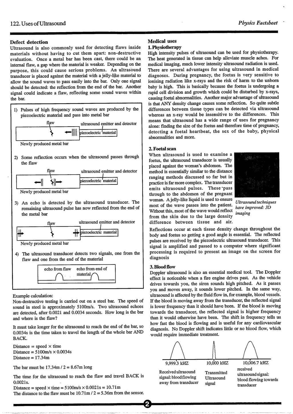
82
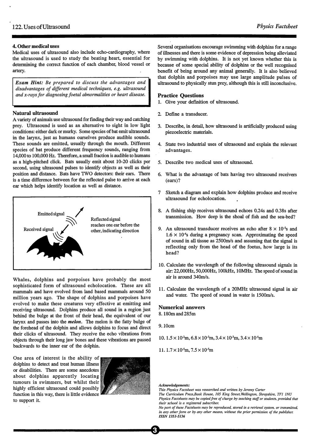
83
84
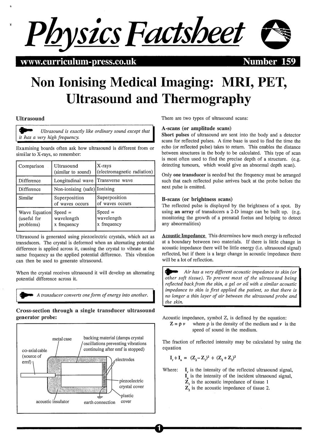
85
86

87
88
89 PhysicsFactsheet Number 75 Line Spectra The purpose of this Factsheet is to explain the appearance, origin and significance of Line Spectra. Before studying the Factsheet, you should make sure that you are familiar with the idea of a spectrum from your GCSE course, and with the ideas of quantization of energy levels in an atom. These ideas of Line Spectra are an important introduction to the understanding of the ideas of Factsheet 51 The Electromagnetic Doppler Effect and the Expanding Universe. Questions on line spectra are likely to occur on the PHY 4 Paper and also on PHY 6, the Synthesis Paper. Appearance of Line Spectra You will be familiar with the idea of a continuous spectrum, as produced by a prism. As the name suggests, line spectra consist not of a continuous band of different colours, but of discrete, separate lines. Each line is of a given frequency (wavelength), representative of a particular element. A line spectrum consists of discrete lines, each typical of the element concered. Observing Line Spectra in the laboratory Emission line spectra may be observed in the laboratory by viewing a discharge tube with a diffraction grating. The tube contains a particular element, e.g., sodium, which, when operated at appropriate voltage, vaporises. The hot vapour emits light. The diffraction grating allows the spectrum to be viewed, rather like the prism does for a continuous spectrum. High voltage Origin of line spectra An emission line spectrum is produced by a hot gaseous element. At high temperatures the electrons of the atoms are excited into higher energy levels. When they drop back to a lower level, the energy is emitted at a specific frequency (wavelength) depending on the energy gap between the levels, determined by the equation: E = hf Where E = energy level gap (J), f = frequency of the observed spectral line (Hz) h = Planck s constant. The observed lines are of frequency f, determined by the energy level gap and derived from the equation E = hf N.B. The energy levels may well be given in ev rather than J, so the figure must be multiplied by to convert ev to J. Significance of Line spectra The existence of line spectra provides evidence for the existence of quantized energy levels in the atom. Observations of the line spectra for hydrogen the Lyman, Balmer, Paschen and Bracket Series enabled the energy levels of the single electron of the hydrogen atom to be established and agreement between experimental evidence and predictions of the theory is very good, thus giving confidence in the theory. Electron transitions for the hydrogen atom =7 n =6 n =5 n =4 Brackett series E(n) to E(n=4) n =3 Paschen series E(n) to E(n=3) n =2 Balmer series E(n) to E(n=2) Red Red yellow green blue violet n =1 Lyman series E(n) to E(n=1) intensity wavelength Calculations of the frequencies of lines in spectra Example:The ground state for the electron in a hydrogen atom is 13.6 ev, the first excited state is 3.4eV. Calculate the frequency of the line in the spectrum representing this transition. E = hf, so ( ) = f Line spectra are observed by viewing a disharge tube with a diffraction grating f = = Hz
90 75. Line Spectra Physics Factsheet Absorption Spectra If white light (i.e. radiation of all frequencies this term is used for the whole EM spectrum, not just visible light) passes through a cooler vapour, then the spectrum observed is of a continuous coloured spectrum with dark lines in the positions where the bright lines would have been in an emission spectrum. This is known as an absorption spectrum. The absorption spectrum is formed as the vapour absorbs specific frequencies from white light. These frequencies are linked to the energies required for the electrons to jump into higher excited states. When the electrons later drop back into lower states, they emit radiation at these same frequencies. However this radiation is emitted in all directions, so the intensity in the orginal direction is reduced. An absorption spectrum consists of dark lines where the bright lines would have been in an emission spectrum. It is formed when white light passes through a cooler vapour. Importance of absorption spectra Observations of the absorption spectra of the light from distant stars has been used to identify which elements are present in the star. The white light passes through the cooler vapours of the outer layers of the star, forming the absorption spectrum. The positions of the dark lines can be compared with emission spectra of known elements on Earth. Absorption spectra indicate what elements are present in stars. Doppler Shift of line spectra from distant stars. Factsheet 51 deals with this important aspect of the use of line spectra. Known spectral lines are found to be shifted slightly towards lower frequencies (Red Shift). One explanation of this is that the source is moving away and the speed of recession can be calculated from the theory. This provides evidence to support the Big Bang theory of the origin of the Universe. Red Shift of line spectra suggests that galaxies are moving away from each other, and this supports the Big Bang theory of the origin of the Universe. Exam Workshop This is a typical poor student s answer to an exam question. The comments explain what is wrong with the answers and how they can be improved. The examiner s mark scheme is given below. (a) Describe how you would produce and observe an emission line spectrum in the laboratory. (2) You would look at a discharge bulb through a slit 0/2 The candidate has incorrectly described it as a bulb rather than a discharge lamp, and has indicated a slit rather than a diffraction grating. (b) Describe what the spectrum would look like. (1) A series of lines 1/1 While this is a very simplistic description, it is adequate for 1 mark. If more marks were allocated for the question, then a better description would be: a series of discrete bright lines against a dark background. (c) Explain the origin of emission line spectra (3) When the electrons in an atom change energy the line is emitted. 1/3 The candidate has shown understanding of energy change, but given no idea of quantized levels. (d) Explain how observation of absorption spectra helps to determine the elemental make-up of a star. (4) Each line represents a particular element, so you can tell which elements are there. 1/4 The candidate has some understanding of the link between the lines and the element, but this is obviously insufficient for 4 marks Examiner s Answers (a) You would view a gas discharge lamp with a diffraction grating. (b) The spectrum is a series of discrete bright lines against a dark background. (c) Energy levels for the electrons in the atom are quantized. When an excited electron drops back from a higher level to a lower level, the energy is emitted as a photon of frequency given by: E = hf. (d) Absorption spectra are produced when white light passes through a cooler vapour (such as the atmosphere of a star). Dark lines appear where bright ones would have been in the emission spectrum for a particular element, so comparison with known element emission spectra identifies the elements. Typical Exam Question (a) Decribe the appearance and origin of an emission line spectrum. (5) (b) Discus the similarities and differences between emission spectra and absorption spectra. You may be awarded a mark for the clarity of your answer. (5) (a) An emission line spectrum consists of discrete bright lines against a dark background. It arises because electrons in the atom cannot take any value of energy, only certain allowable levels. In a hot vapour, the electrons are excited into higher energy levels and when they drop back to the ground state in stages, the energy difference between levels is emitted as a photon of frequency given by E = hf, where E is the energy difference, h is Planck s constant and f the frequency. (b) Both emission and absorption spectra consist of discrete lines at certain frequencies, but the absorption spectrum has bright lines against a dark background at the same frequencies which the emission spectrum has as bright lines against a dark background. Both occur because of electron movement between allowable levels, but emission are due to excited electrons dropping down into lower levels, whereas absorption are due to electrons being excited into higher levels. Emission occurs from hot vapours, whereas absorption occurs when white light (all frequencies) passes through cooler vapour. 2
91 75. Line Spectra Physics Factsheet Questions 1. What is an emission line spectrum? 2. Why does an absorption line spectrum occur when white light passes through a cooler vapour? 3. How can observation of absorption spectra be used to identify the elements present in the atmosphere of a star? 4. (a) What is meant by Red Shift of line spectra? (b) Explain how the red shift of the line spectra of distance galaxies provides evidence to support the Big Bang theory. 5. Explain how emission spectra support the idea of quantization of energy levels. 6. The diagram shows some of the energy levels for atomic hydrogen. Answers 1. See text. 2. When white light passes through a cooler vapour, frequencies appropriate to allowable transitions between energy levels in the atom are absorbed and electrons go into higher energy levels. Later, they drop back, but the photons are emitted in all directions, whereas the original energy was absorbed from the forward direction, so the specific frequency appears darker. 3. The frequencies of absorption lines in the spectra from stars can be compared with the emission lines in spectra of known elements and the elements in the atmosphere of the star identified. 4. (a) Red Shift is the slight shifting of known frequencies in the absorption spectra of distant stars to lower values (longer wavelength). D C B A ev -1.5 ev -3.4 ev ev (b) The most likely explanation for the red shift is that the source is moving away (Doppler effect). This implies that galaxies are now moving away from one another, i.e. they were originally all in the same place Big Bang theory. 5. From a study of the Lyman series of lines in a hydrogen spectrum, possible values for the energy levels can then be worked out. These values can then be used to predict other series which should exist. Good agreement between theory and observation confirms the theory. (a) Calculate the wavelength of the line which would appear in a line spectrum for the transition between the levels marked A and C. (b) Which transition represents a photon absorbed with the shortest wavelength. (c) Which transition represents a photon emitted with the longest wavelength. 6. (a) E = ( ) J so, f = , c = fλ so λ = = m ( ) (b) A D. In absorption, the electron is excited to a higher level. Shortest wavelength is the highest frequency, therefore the largest energy gap. (c) D C. In emission, the electron drops back to a lower level. Longest wavelength is lowest frequency, therefore the smallest energy gap Acknowledgements: This Physics Factsheet was researched and written by Janet Jones The Curriculum Press,Bank House, 105 King Street, Wellington, Shropshire, TF1 1NU Physics Factsheets may be copied free of charge by teaching staff or students, provided that their school is a registered subscriber. No part of these Factsheets may be reproduced, stored in a retrieval system, or transmitted, in any other form or by any other means, without the prior permission of the publisher. ISSN
92
93
94
95
96

97
98
Which one of the following graphs correctly shows the relationship between potential difference (V) and current (I) for a filament lamp?
 and current (I) for a filament lamp?") Questions Q1. Select one answer from A to D and put a cross in the box ( ) Which one of the following graphs correctly shows the relationship between potential difference (V) and current (I) for a filament
Questions Q1. Select one answer from A to D and put a cross in the box ( ) Which one of the following graphs correctly shows the relationship between potential difference (V) and current (I) for a filament
3 Electric current, resistance, energy and power
 3 3.1 Introduction Having looked at static charges, we will now look at moving charges in the form of electric current. We will examine how current passes through conductors and the nature of resistance
A) Know that electric current is the rate of flow of charge 1 What is current?
 Know that electric current is the rate of flow of charge 1 What is current?") PHYSICS AS UNIT 1 SECTION 3: CURRENT ELECTRiCiTY Question Answer A) Know that electric current is the rate of flow of charge 1 What is current? The rate of flow of charge Measured in amps (A) Symbol is
PHYSICS AS UNIT 1 SECTION 3: CURRENT ELECTRiCiTY Question Answer A) Know that electric current is the rate of flow of charge 1 What is current? The rate of flow of charge Measured in amps (A) Symbol is
Chapter 3: Electric Current And Direct-Current Circuits
 Chapter 3: Electric Current And Direct-Current Circuits 3.1 Electric Conduction 3.1.1 Describe the microscopic model of current Mechanism of Electric Conduction in Metals Before applying electric field
1 Written and composed by: Prof. Muhammad Ali Malik (M. Phil. Physics), Govt. Degree College, Naushera
, Govt. Degree College, Naushera") CURRENT ELECTRICITY Q # 1. What do you know about electric current? Ans. Electric Current The amount of electric charge that flows through a cross section of a conductor per unit time is known as electric
CURRENT ELECTRICITY Q # 1. What do you know about electric current? Ans. Electric Current The amount of electric charge that flows through a cross section of a conductor per unit time is known as electric
5. ELECTRIC CURRENTS
 5. ELECTRIC CURRENTS TOPIC OUTLINE Section Recommended Time Giancoli Section 5.1 Potential Difference, Current, Resistance 5.2 Electric Circuits 3h 19.1, 19.2 6.2 Electric Field and Force 6.3 Magnetic
Electric Currents. Resistors (Chapters 27-28)
") Electric Currents. Resistors (Chapters 27-28) Electric current I Resistance R and resistors Relation between current and resistance: Ohm s Law Resistivity ρ Energy dissipated by current. Electric power
Electric Currents. Resistors (Chapters 27-28) Electric current I Resistance R and resistors Relation between current and resistance: Ohm s Law Resistivity ρ Energy dissipated by current. Electric power
Figure 1. Load resistance / Ω. Use data from Figure 1 to calculate the current in the load at the peak power. (3) Page 1 of 27
 Page 1 of 27") Figure shows data for the variation of the power output of a photovoltaic cell with load resistance. The data were obtained by placing the cell in sunlight. The intensity of the energy from the Sun incident
Figure shows data for the variation of the power output of a photovoltaic cell with load resistance. The data were obtained by placing the cell in sunlight. The intensity of the energy from the Sun incident
Physics Department. CfE Higher Unit 3: Electricity. Problem Booklet
 Physics Department CfE Higher Unit 3: Electricity Problem Booklet Name Class 1 Contents Exercise 1: Monitoring and measuring a.c. Exercise 2: Current, voltage, power and resistance Exercise 3: Electrical
PhysicsAndMathsTutor.com
 Electricity May 02 1. The graphs show the variation with potential difference V of the current I for three circuit elements. PhysicsAndMathsTutor.com When the four lamps are connected as shown in diagram
Answers to examination-style questions. Answers Marks Examiner s tips
 End-of-unit (a) (i) 94 protons This is the proton number Z. (ii) 45 neutrons Number of neutrons is found from (nucleon number proton number) = (A Z) = 239 94 (iii) 93 electrons A neutral atom would have
Physics 142 Steady Currents Page 1. Steady Currents
 Physics 142 Steady Currents Page 1 Steady Currents If at first you don t succeed, try, try again. Then quit. No sense being a damn fool about it. W.C. Fields Electric current: the slow average drift of
REVISED HIGHER PHYSICS REVISION BOOKLET ELECTRONS AND ENERGY
 REVSED HGHER PHYSCS REVSON BOOKLET ELECTRONS AND ENERGY Kinross High School Monitoring and measuring a.c. Alternating current: Mains supply a.c.; batteries/cells supply d.c. Electrons moving back and forth,
Question 3: How is the electric potential difference between the two points defined? State its S.I. unit.
 EXERCISE (8 A) Question : Define the term current and state its S.I unit. Solution : Current is defined as the rate of flow of charge. I = Q/t Its S.I. unit is Ampere. Question 2: Define the term electric
Unit 2. Current, Voltage and Resistance
 Strand G. Electricity Unit 2. Current, Voltage and Resistance Contents Page Current 2 Potential Difference, Electromotive Force and Power 5 Resistance and Ohm s Law 9 G.2.1. Current In a metallic conductor
Physics Module Form 5 Chapter 2- Electricity GCKL 2011 CHARGE AND ELECTRIC CURRENT
 2.1 CHARGE AND ELECTRIC CURRENT Van de Graaf 1. What is a Van de Graaff generator? Fill in each of the boxes the name of the part shown. A device that produces and store electric charges at high voltage
Electric Current & DC Circuits How to Use this File Electric Current & DC Circuits Click on the topic to go to that section Circuits
 Slide 1 / 127 Slide 2 / 127 Electric Current & DC Circuits www.njctl.org Slide 3 / 127 How to Use this File Slide 4 / 127 Electric Current & DC Circuits Each topic is composed of brief direct instruction
Electric Current & DC Circuits
 Electric Current & DC Circuits Circuits Click on the topic to go to that section Conductors Resistivity and Resistance Circuit Diagrams Measurement EMF & Terminal Voltage Kirchhoff's Rules Capacitors*
UNIT 3 ELECTRIC CHARGE ELECTRIC CIRCUITS: ELECTRIC CHARGE:
 AS Physics 9702 unit 3: Electric Charge 1 UNIT 3 ELECTRIC CHARGE ELECTRIC CIRCUITS: For the current to exist it must have a complete path of conductors. This complete path of conductors is called electric
Circuits. Electric Current & DC Circuits. Slide 1 / 127. Slide 2 / 127. Slide 3 / 127. Slide 4 / 127. Slide 5 / 127. Slide 6 / 127
 Slide 1 / 127 Slide 2 / 127 New Jersey Center for Teaching and Learning Electric Current & DC Circuits www.njctl.org Progressive Science Initiative This material is made freely available at www.njctl.org
Which of the following is the SI unit of gravitational field strength?
 T5-2 [122 marks] 1. A cell is connected in series with a 2.0Ω resistor and a switch. The voltmeter is connected across the cell and reads 12V when the switch is open and 8.0V when the switch is closed.
A Review of Circuitry
 1 A Review of Circuitry There is an attractive force between a positive and a negative charge. In order to separate these charges, a force at least equal to the attractive force must be applied to one
Electric Currents and Circuits
 Nicholas J. Giordano www.cengage.com/physics/giordano Chapter 19 Electric Currents and Circuits Marilyn Akins, PhD Broome Community College Electric Circuits The motion of charges leads to the idea of
NATIONAL QUALIFICATIONS CURRICULUM SUPPORT. Physics. Electricity. Questions and Solutions. James Page Arthur Baillie [HIGHER]
![NATIONAL QUALIFICATIONS CURRICULUM SUPPORT. Physics. Electricity. Questions and Solutions. James Page Arthur Baillie [HIGHER]](/thumbs/86/93982339.jpg "NATIONAL QUALIFICATIONS CURRICULUM SUPPORT. Physics. Electricity. Questions and Solutions. James Page Arthur Baillie [HIGHER]") NTIONL QULIFICTIONS CURRICULUM SUPPORT Physics Electricity Questions and Solutions James Page rthur Baillie [HIGHER] The Scottish Qualifications uthority regularly reviews the arrangements for National
NTIONL QULIFICTIONS CURRICULUM SUPPORT Physics Electricity Questions and Solutions James Page rthur Baillie [HIGHER] The Scottish Qualifications uthority regularly reviews the arrangements for National
HIGHER PHYSICS ELECTRICITY
 H HIGHER PHYSICS ELECTRICITY ALTERNATING CURRENT An alternating current (a.c.) periodically changes direction contrast this to direct current (d.c.), which only flows in one direction. Although it is possible
Theme 5: Electricity in the Home
 Theme 5: Electricity in the Home Static Electricity WHAT IS STATIC ELECTRICITY? Everything we see is made up of tiny little parts called atoms. So what are atoms made of? In the middle of each atom is
Insulators Non-metals are very good insulators; their electrons are very tightly bonded and cannot move.
 SESSION 11: ELECTRIC CIRCUITS Key Concepts Resistance and Ohm s laws Ohmic and non-ohmic conductors Series and parallel connection Energy in an electric circuit X-planation 1. CONDUCTORS AND INSULATORS
Chapter 3: Electric Current and Direct-Current Circuit
 Chapter 3: Electric Current and Direct-Current Circuit n this chapter, we are going to discuss both the microscopic aspect and macroscopic aspect of electric current. Direct-current is current that flows
Section 1 Electric Charge and Force
 CHAPTER OUTLINE Section 1 Electric Charge and Force Key Idea questions > What are the different kinds of electric charge? > How do materials become charged when rubbed together? > What force is responsible
You should be able to demonstrate and show your understanding of:
 OCR B Physics H557 Module 3: Physics in Action You should be able to demonstrate and show your understanding of: 3.1: Communication 3.1.1: Imaging and Signalling The formation of a real image by a thin
Circuits. Circuits. Electric Current & DC Circuits. current and circuits presentation March 22, How to Use this File.
 New Jersey Center for Teaching and Learning Electric Current & DC Circuits Progressive Science Initiative This material is made freely available at www.njctl.org and is intended for the non commercial
Electro - Principles I
 Electro - Principles I Page 10-1 Atomic Theory It is necessary to know what goes on at the atomic level of a semiconductor so the characteristics of the semiconductor can be understood. In many cases a
Farr High School HIGHER PHYSICS. Unit 3 Electricity. Question Booklet
 Farr High School HIGHER PHYSICS Unit 3 Electricity Question Booklet 1 MONITORING ND MESURING.C. 1. What is the peak voltage of the 230 V mains supply? The frequency of the mains supply is 50 Hz. How many
CLASS X- ELECTRICITY
 Conductor- Insulator: Materia Materials through which electric current cannot pass are called insulators. Electric Circuit: A continuous a CLASS X- ELECTRICITY als through which electric current can pass
Capacitance. A different kind of capacitor: Work must be done to charge a capacitor. Capacitors in circuits. Capacitor connected to a battery
 Capacitance The ratio C = Q/V is a conductor s self capacitance Units of capacitance: Coulomb/Volt = Farad A capacitor is made of two conductors with equal but opposite charge Capacitance depends on shape
Resistance Learning Outcomes
 Resistance Learning Outcomes Define resistance and give its unit. Solve problems about resistance. State Ohm s Law. HL: Derive the formulas for resistors in series and parallel. Solve problems about resistors
An ion follows a circular path in a uniform magnetic field. Which single change decreases the radius of the path?
 T5-1 [237 marks] 1. A circuit is formed by connecting a resistor between the terminals of a battery of electromotive force (emf) 6 V. The battery has internal resistance. Which statement is correct when
TSOKOS LSN 5-1 TO 5-5 TEST REVIEW
 IB HYSICS Name: DEIL HYSICS eriod: Date: # Marks: BADDEST CLASS ON CAMUS TSOKOS LSN 5-1 TO 5-5 TEST REIEW 4. This question is about forces on charged particles. (a) (b) A charged particle is situated in
Resistance Learning Outcomes. Resistance Learning Outcomes. Resistance
 Resistance Learning Outcomes Define resistance and give its unit. Solve problems about resistance. State Ohm s Law. HL: Derive the formulas for resistors in series and parallel. Solve problems about resistors
Electron Theory of Charge. Electricity. 1. Matter is made of atoms. Refers to the generation of or the possession of electric charge.
 Electricity Refers to the generation of or the possession of electric charge. There are two kinds of electricity: 1. Static Electricity the electric charges are "still" or static 2. Current Electricity
FXA 2008 ELECTRIC CHARGE (Q) 1. Candidates should be able to : Electric charge is a property possessed by protons and electrons.
 1. Candidates should be able to : Electric charge is a property possessed by protons and electrons.") ELECTRIC CHARGE (Q) 1 Candidates should be able to : Explain that electric current is a net flow of charged particles. Explain that electric current in a metal is due to the movement of electrons, whereas
ELECTRIC CHARGE (Q) 1 Candidates should be able to : Explain that electric current is a net flow of charged particles. Explain that electric current in a metal is due to the movement of electrons, whereas
Monday July 14. Capacitance demo slide 19 Capacitors in series and parallel slide 33 Elmo example
 Monday July 14 Lecture 5 Capacitance demo slide 19 Capacitors in series and parallel slide 33 Elmo example Lecture 6 Currents and esistance Lecture 9 Circuits Wear Microphone 1 3 Lecture 6 Current and
Chapter 9. Electric current. Developing ideas
 Chapter 9 Electric current Objectives e-learning Developing ideas Electricity plays a vital part in our lives. We use electricity as a way of transferring energy from place to place for heating, lighting
In this unit, we will examine the movement of electrons, which we call CURRENT ELECTRICITY.
 Recall: Chemistry and the Atom! What are the 3 subatomic Where are they found in the particles? atom? What electric charges do they have? How was a positive ion created? How was a negative ion created?
AP Physics C - E & M
 AP Physics C - E & M Current and Circuits 2017-07-12 www.njctl.org Electric Current Resistance and Resistivity Electromotive Force (EMF) Energy and Power Resistors in Series and in Parallel Kirchoff's
Unit 6 Current Electricity and Circuits
 Unit 6 Current Electricity and Circuits 2 Types of Electricity Electricity that in motion. Electricity that in motion. Occurs whenever an moves through a. 2 Types of Current Electricity Electricity that
Electric charge is conserved the arithmetic sum of the total charge cannot change in any interaction.
 Electrostatics Electric charge is conserved the arithmetic sum of the total charge cannot change in any interaction. Electric Charge in the Atom Atom: Nucleus (small, massive, positive charge) Electron
Big idea (age 11-14) PEM: Electricity and magnetism
 PEM: Electricity and magnetism") Physics Big idea (age 11-14) PEM: Electricity and magnetism What s the big idea? The familiar everyday world we live in is largely a consequence of the properties and behaviour of electric charge. Matter
Physics Big idea (age 11-14) PEM: Electricity and magnetism What s the big idea? The familiar everyday world we live in is largely a consequence of the properties and behaviour of electric charge. Matter
SIMPLE D.C. CIRCUITS AND MEASUREMENTS Background
 SIMPLE D.C. CICUITS AND MEASUEMENTSBackground This unit will discuss simple D.C. (direct current current in only one direction) circuits: The elements in them, the simple arrangements of these elements,
Class 8. Resistivity and Resistance Circuits. Physics 106. Winter Press CTRL-L to view as a slide show. Class 8. Physics 106.
 and Circuits and Winter 2018 Press CTRL-L to view as a slide show. Last time we learned about Capacitance Problems Parallel-Plate Capacitors Capacitors in Circuits Current Ohm s Law and Today we will learn
CHAPTER 1 ELECTRICITY
 CHAPTER 1 ELECTRICITY Electric Current: The amount of charge flowing through a particular area in unit time. In other words, it is the rate of flow of electric charges. Electric Circuit: Electric circuit
Work Energy & Power. September 2000 Number Work If a force acts on a body and causes it to move, then the force is doing work.
 PhysicsFactsheet September 2000 Number 05 Work Energy & Power 1. Work If a force acts on a body and causes it to move, then the force is doing work. W = Fs W = work done (J) F = force applied (N) s = distance
Higher Physics Electricity Notes
 Higher Physics Electricity Notes Teachers Booklet Learning Outcomes Monitoring and measuring a.c. This builds on information from Electricity and Energy booklet 1: Electrical charge carriers and fields.
Section 1: Electric Fields
 PHY 132 Outline of Lecture Notes i Section 1: Electric Fields A property called charge is part of the basic nature of protons and electrons. Large scale objects become charged by gaining or losing electrons.
Physics 7B-1 (A/B) Professor Cebra. Winter 2010 Lecture 2. Simple Circuits. Slide 1 of 20
 Professor Cebra. Winter 2010 Lecture 2. Simple Circuits. Slide 1 of 20") Physics 7B-1 (A/B) Professor Cebra Winter 2010 Lecture 2 Simple Circuits Slide 1 of 20 Conservation of Energy Density In the First lecture, we started with energy conservation. We divided by volume (making
Physics 7B-1 (A/B) Professor Cebra Winter 2010 Lecture 2 Simple Circuits Slide 1 of 20 Conservation of Energy Density In the First lecture, we started with energy conservation. We divided by volume (making
Cathkin High School Physics Department. CfE Higher Unit 3 Electricity. Summary Notes
 Cathkin High School Physics Department CfE Higher Unit 3 Electricity Summary Notes Name Class 3.1 Electrons and Energy Monitoring and measuring alternating current Alternating current Previously, you learned
Questions Q1. Select one answer from A to D and put a cross in the box ( )
") Questions Q1. Select one answer from A to D and put a cross in the box ( ) The resistance of a length of copper wire is 6 Ω. A second piece of copper wire has twice the length and twice the cross-sectional
Questions Q1. Select one answer from A to D and put a cross in the box ( ) The resistance of a length of copper wire is 6 Ω. A second piece of copper wire has twice the length and twice the cross-sectional
UNIT 3: Electric charge.
 UNIT 3: Electric charge Recommended Prior Knowledge Students should be aware of the two types of charge, charging by friction and by induction. They should be able to distinguish between conductors and
Where I is the current in Amperes, q is the charge in coulombs, and t is the time in seconds.
 CURRENT ELECTRICITY What is current? All of use like to ask this little question, which is quite easily answered, but not so easily understood. Current is the flow of charges. In other words, the flow,
UNIT II CURRENT ELECTRICITY
 UNIT II CUENT ELECTICITY Weightage : 07 Marks Electric current; flow of electric charges in a metllic conductor, drift velocity, mobility and their relation with electric current. Ohm s law electrical
AP Physics C - E & M
 Slide 1 / 27 Slide 2 / 27 AP Physics C - E & M Current, Resistance & Electromotive Force 2015-12-05 www.njctl.org Slide 3 / 27 Electric Current Electric Current is defined as the movement of charge from
52 VOLTAGE, CURRENT, RESISTANCE, AND POWER
 52 VOLTAGE, CURRENT, RESISTANCE, AND POWER 1. What is voltage, and what are its units? 2. What are some other possible terms for voltage? 3. Batteries create a potential difference. The potential/voltage
Electric Current. Chapter 17. Electric Current, cont QUICK QUIZ Current and Resistance. Sections: 1, 3, 4, 6, 7, 9
 Electric Current Chapter 17 Current and Resistance Sections: 1, 3, 4, 6, 7, 9 Whenever electric charges of like signs move, an electric current is said to exist The current is the rate at which the charge
Lesson Plan: Electric Circuits (~130 minutes) Concepts
 Concepts") Lesson Plan: Electric Circuits (~130 minutes) Concepts 1. Electricity is the flow of electric charge (electrons). 2. Electric Charge is a property of subatomic particles. 3. Current is the movement of
Lesson Plan: Electric Circuits (~130 minutes) Concepts 1. Electricity is the flow of electric charge (electrons). 2. Electric Charge is a property of subatomic particles. 3. Current is the movement of
Waves Final Review. Name: Date: 1. On which one of the following graphs is the wavelength λ and the amplitude a of a wave correctly represented?
 Name: Date: Waves Final Review 1. On which one of the following graphs is the wavelength λ and the amplitude a of a wave correctly represented? A. Displacement λ a Distance along wave B. Displacement λ
Prelim Revision. Questions and Answers. Electricity
 Prelim Revision Questions and Answers Electricity SECTION A Answer questions on the answer sheet 8. Specimen Paper The diagram shows an 8V supply connected to two lamps. The supply has negligible internal
1. The diagram shows the electric field lines produced by an electrostatic focussing device.
 1. The diagram shows the electric field lines produced by an electrostatic focussing device. Which one of the following diagrams best shows the corresponding equipotential lines? The electric field lines
UNIVERSITY OF MALTA THE MATRICULATION CERTIFICATE EXAMINATION ADVANCED LEVEL PHYSICS. May 2007 EXAMINERS REPORT
 UNIVERSITY OF MALTA THE MATRICULATION CERTIFICATE EXAMINATION ADVANCED LEVEL PHYSICS May 2007 EXAMINERS REPORT MATRICULATION AND SECONDARY EDUCATION CERTIFICATE EXAMINATIONS BOARD AM Physics May 2007 Session
St Olave s Grammar School. AS Physics Mock Revision Checklist
 St Olave s Grammar School Mock Practical skills.. a Can you design experiments, including ones to solve problems set in a practical context?.. b Can you identify the variables that must be controlled in
Chapter 17. Current and Resistance. Sections: 1, 3, 4, 6, 7, 9
 Chapter 17 Current and Resistance Sections: 1, 3, 4, 6, 7, 9 Equations: 2 2 1 e r q q F = k 2 e o r Q k q F E = = I R V = A L R ρ = )] ( 1 [ o o T T + = α ρ ρ V I V t Q P = = R V R I P 2 2 ) ( = = C Q
Electric Force and Charge. Electric Force and Charge. Electric Force and Charge. Electric Force and Charge. Electric Force and Charge
 Hewitt/Lyons/Suchocki/Yeh Conceptual Integrated Science Chapter 7 ELECTRICITY AND MAGNETISM Electric forces can attract some objects and repel others Electric charge: the fundamental quantity that underlies
PHYSICS NOTES. W.R.David. Current Electricity
 PHYSICS NOTES W.R.David Current Electricity Syllabus:- Content Electric current Potential difference Resistance and resistivity Sources of electromotive force. Learning Outcomes Candidates should be able
Tactics Box 23.1 Using Kirchhoff's Loop Law
 PH203 Chapter 23 solutions Tactics Box 231 Using Kirchhoff's Loop Law Description: Knight/Jones/Field Tactics Box 231 Using Kirchhoff s loop law is illustrated Learning Goal: To practice Tactics Box 231
8. Electric circuit: The closed path along which electric current flows is called an electric circuit.
 GIST OF THE LESSON 1. Positive and negative charges: The charge acquired by a glass rod when rubbed with silk is called positive charge and the charge acquired by an ebonite rod when rubbed with wool is
Resistivity and Temperature Coefficients (at 20 C)
") Homework # 4 Resistivity and Temperature Coefficients (at 0 C) Substance Resistivity, Temperature ( m) Coefficient, (C ) - Conductors Silver.59 x 0-0.006 Copper.6 x 0-0.006 Aluminum.65 x 0-0.0049 Tungsten
Homework # 4 Resistivity and Temperature Coefficients (at 0 C) Substance Resistivity, Temperature ( m) Coefficient, (C ) - Conductors Silver.59 x 0-0.006 Copper.6 x 0-0.006 Aluminum.65 x 0-0.0049 Tungsten
YEAR 10 PHYSICS IGCSE Forces
 YEAR 10 PHYSICS IGCSE Forces 1.1 I understand the importance of units and know a range of units for mass, length, velocity (speed), acceleration, force and time. Page.. 1.2 I can plot and interpret distance-time
Physics 1302W.400 Lecture 21 Introductory Physics for Scientists and Engineering II
 Physics 1302W.400 Lecture 21 Introductory Physics for Scientists and Engineering II In today s lecture, we will learn to: Calculate the resistance of a conductor depending on the material and shape Apply
An Introduction to Electricity and Circuits
 An Introduction to Electricity and Circuits Materials prepared by Daniel Duke 4 th Sept 2013. This document may be copied and edited freely with attribution. This course has been designed to introduce
AC vs. DC Circuits. Constant voltage circuits. The voltage from an outlet is alternating voltage
 Circuits AC vs. DC Circuits Constant voltage circuits Typically referred to as direct current or DC Computers, logic circuits, and battery operated devices are examples of DC circuits The voltage from
Flow Rate is the NET amount of water passing through a surface per unit time
 Electric Current An Analogy Water Flow in a Pipe H 2 0 gallons/minute Flow Rate is the NET amount of water passing through a surface per unit time Individual molecules are bouncing around with speeds of
Lecture 6 Current and Resistance Ch. 26
 Lecture 6 Current and esistance Ch. 6 Cartoon -nvention of the battery and Voltaic Cell Warm-up problem Topics What is current? Current density Conservation of Current esistance Temperature dependence
Note on Posted Slides. Flow of Charge. Electricity/Water Analogy: Continuing the Analogy. Electric Current
 Note on Posted Slides These are the slides that I intended to show in class on Tue. Mar. 18, 2014. They contain important ideas and questions from your reading. Due to time constraints, I was probably
physics 4/7/2016 Chapter 31 Lecture Chapter 31 Fundamentals of Circuits Chapter 31 Preview a strategic approach THIRD EDITION
 Chapter 31 Lecture physics FOR SCIENTISTS AND ENGINEERS a strategic approach THIRD EDITION randall d. knight Chapter 31 Fundamentals of Circuits Chapter Goal: To understand the fundamental physical principles
Basic Electricity. Unit 2 Basic Instrumentation
 Basic Electricity Unit 2 Basic Instrumentation Outlines Terms related to basic electricity-definitions of EMF, Current, Potential Difference, Power, Energy and Efficiency Definition: Resistance, resistivity
What colour is the insulation around the wire connected to the live pin inside the plug? ... (1) (1)
 (1)") Q. Diagram shows a hairdryer. Diagram 2 shows how the heaters and fan of the hairdryer are connected to a 3-pin plug. The hairdryer does not have an earth wire. (a) What colour is the insulation around
Q. Diagram shows a hairdryer. Diagram 2 shows how the heaters and fan of the hairdryer are connected to a 3-pin plug. The hairdryer does not have an earth wire. (a) What colour is the insulation around
11. ELECTRIC CURRENT. Questions and Answers between the forces F e and F c. 3. Write the difference between potential difference and emf. A.
 CLSS-10 1. Explain how electron flow causes electric current with Lorentz-Drude theory of electrons?. Drude and Lorentz, proposed that conductors like metals contain a large number of free electrons while
EXPERIMENT 12 OHM S LAW
 EXPERIMENT 12 OHM S LAW INTRODUCTION: We will study electricity as a flow of electric charge, sometimes making analogies to the flow of water through a pipe. In order for electric charge to flow a complete
Physics Module Form 5 Chapter 2- Electricity GCKL 2011 CHARGE AND ELECTRIC CURRENT
 2.1 CHARGE AND ELECTRIC CURRENT Van de Graaf 1. What is a Van de Graaff generator? Fill in each of the boxes the name of the part shown. A device that... and... at high voltage on its dome. dome 2. You
TOPIC 25 RESISTANCE COVERING: R = VII = 3/0.25 = 12 Q
 TOPIC 25 RESISTANCE COVERING: simple measurement of resistance; resistance and resistivity; I-V characteristics; resistors in series and in parallel; e.m.f.; internal resistance; power. In the previous
PH 102 Exam I N N N N. 3. Which of the following is true for the electric force and not true for the gravitational force?
 Name Date INSTRUCTIONS PH 102 Exam I 1. nswer all questions below. ll problems have equal weight. 2. Clearly mark the answer you choose by filling in the adjacent circle. 3. There will be no partial credit
Gr. 11 Physics Electricity
 Gr. 11 Physics Electricity This chart contains a complete list of the lessons and homework for Gr. 11 Physics. Please complete all the worksheets and problems listed under Homework before the next class.
Higher Physics. Electricity. Summary Notes. Monitoring and measuring a.c. Current, potential difference, power and resistance
 Higher Physics Electricity Summary Notes Monitoring and measuring a.c. Current, potential difference, power and resistance Electrical sources and internal resistance Capacitors Conductors, semiconductors
Closed loop of moving charges (electrons move - flow of negative charges; positive ions move - flow of positive charges. Nucleus not moving)
") Unit 2: Electricity and Magnetism Lesson 3: Simple Circuits Electric circuits transfer energy. Electrical energy is converted into light, heat, sound, mechanical work, etc. The byproduct of any circuit
Unit 2: Electricity and Magnetism Lesson 3: Simple Circuits Electric circuits transfer energy. Electrical energy is converted into light, heat, sound, mechanical work, etc. The byproduct of any circuit
The child becomes electrically charged when he goes down the slide
 P4 Revision Questions Q. The figure below shows a slide in a children s playground. (a) A child of mass 8 kilograms goes down the slide. The vertical distance from the top to the bottom of the slide is
Chapter 24: Electric Current
 Chapter 24: Electric Current Current Definition of current A current is any motion of charge from one region to another. Suppose a group of charges move perpendicular to surface of area A. The current
[This is Unit 2 Physics, Additional Physics. This section comes after Core Physics in an AQA Course (Unit 1)]
![[This is Unit 2 Physics, Additional Physics. This section comes after Core Physics in an AQA Course (Unit 1)]](/thumbs/89/100533139.jpg "[This is Unit 2 Physics, Additional Physics. This section comes after Core Physics in an AQA Course (Unit 1)]") Contents Unit 1: Motion Unit 2: Speeding Up and Slowing Down Unit 3: Work and Energy Unit 4: Static Electricity Unit 5: Current Electricity Unit 6: Mains Electricity Unit 7: Nuclear Physics [This is Unit
Contents Unit 1: Motion Unit 2: Speeding Up and Slowing Down Unit 3: Work and Energy Unit 4: Static Electricity Unit 5: Current Electricity Unit 6: Mains Electricity Unit 7: Nuclear Physics [This is Unit
Summary Notes ALTERNATING CURRENT AND VOLTAGE
 HIGHER CIRCUIT THEORY Wheatstone Bridge Circuit Any method of measuring resistance using an ammeter or voltmeter necessarily involves some error unless the resistances of the meters themselves are taken
Electricity Answers. Current, Potential Difference, Resistor Networks, Resistance and Resistivity
 Electricity Answers Current, Potential Difference, Resistor Networks, Resistance and Resistivity 1. Resistance calculations Evidence of 20 Ω for one arm 1 1 1 = + R 20 20 R = 10 Ω 3 Comment This combination
Revision Guide for Chapter 2
 Revision Guide for Chapter 2 Contents Student s Checklist Revision Notes Electric current and charge... 5 Potential difference... 5 Conductance and resistance... 6 Parallel circuit... 7 Series circuit...
NATIONAL 5 PHYSICS ELECTRICITY
 NATIONAL 5 PHYSICS ELECTRICITY ELECTRICAL CHARGE CARRIERS AND CURRENT Electrical Charge Electrical charge exists in two distinct types positive charge and negative charge. It is also possible for an object