1. How does a light bulb work?
|
|
|
- Sophie Hill
- 5 years ago
- Views:
Transcription


1 AP Physics 1 Lesson 12.a Electric Current and Circuits Outcomes 1. Determine the resistance of a resistor given length, cross-sectional area and length. 2. Relate the movement of charge to differences in potential. 3. Use Ohm s law to solve problems with simple direct current circuits. 4. Determine the effective resistance of a simple circuit with resistors in series, parallel or combination arrangements. 5. Use Kirchoff s Loop Rule to solve problems with simple direct current circuits. 6. Use Kirchoff s Junction Rule to solve problems with simple direct current circuits. 7. Determine the internal resistance of a battery in a circuit. 8. Determine the rate of energy dissipation in simple direct current circuits. 9. Link concepts of energy conservation and specific heat to simple circuits. 10. Determine the total effective resistance of a simple steady state circuit with resistors in series, parallel or combination arrangements. I= V R R= ρ L A R s =R +R 2 +R 3 1 = R p R 1 R 2 R 3 P=IV=I 2 R= V 2 R Name Date Period Engage 1. How does a light bulb work? 2. Draw arrows on the diagram or any other marks to help explain how the light bulb works. 3. Imagine that you are given a bulb, a battery and a wire segment. How would you connect the wire and the battery to get the light bulb to glow? Draw as many working set ups as you can. Explore The teacher will provide your group with a battery, bulb and wire segment. Experiment with these materials until you discover at least two different ways to arrange these materials to make the light bulb glow. 4. Carefully diagram successful arrangements. Explain 5. What general conditions have to be true for the light bulb to light? 1
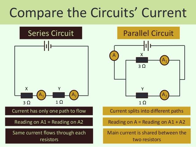
2 Read Notes: A complete loop or path from one end of a battery to the other is referred to as a circuit. An open circuit is one that is not complete and has a gap or separation between one end of the battery and the other. A closed circuit is one that has a complete uninterrupted path from one end of the battery to the other. Explore II Examine the diagram on the right. There are two parallel metal plates. Plate A is covered with negatively charged particles. Plate B is covered with positively charged particles. Charge q ( a negative - charge) is in between the plates and is free to move. 6. Explain what will happen to charge q when it is released. 7. What happens to the velocity of charge A as it approaches plate B? Why? Explore III Examine the drawing on the right. There are two metal plates set up like before. This time there is a barrier preventing charges from directly passing from one plate to the other, but there is a wire connecting the plates. 8. What do you think will happen this time? Notes This arrangement describes the basic components of a simple electric circuit. When a large number of negative charges (or positive charges) are grouped together, there is a large amount of potential energy in the system. If a path is set up that will allow those charges to move to places where they are less concentrated, then they will spontaneously move along that path. That movement of charge along the path is called electric current. When the negative charges move from a state of high concentration to low concentration, the potential energy in the system decreases. Explain III 9. If large numbers of charges squeezed together have high potential energy, what does that potential energy become as the charges move? 2

3 10. What is being done with the electric potential energy in this circuit? Explore IV Read Let s examine charges moving in the wire. When there is no difference in the concentration of charged particles in a circuit, the electrons randomly move from one metal nucleus to another. If a difference in concentration of charge occurs between the ends of the wire, there is a net flow or drift of the electrons from the end with a higher concentration of charge toward the end with the lower concentration of charge. This movement decreases potential energy in the system. Let s examine this flow of charge with a model. The diagram below represents a wire segment. The white circles represent the positively charged nuclei of metal atoms in the wire. Place a coin or small piece of paper over nuclei 1, 2, 3, 4, 5 and 6. They represent the electrons. Now we will apply a voltage to the system. Draw a big (+) on the right hand side of the illustration, and a big (-) on the left hand side of the illustration. The penny covering nucleus 6 is now in a high potential energy state and is attracted to the big (+) charge. Pick it up and place it on the large positive charge you drew on the right hand side of the wire. The electron penny covering nucleus 5 now sees an empty space and will move to the right to cover nucleus #6. Move the electrons covering nucleus 5 in the manner you think appropriate. Repeat this process with the electron covering nucleus 4. 3
4 11. What is the net direction that the electrons are moving? Notes: We call this movement of electrons electron current. 12. What do you notice about the direction the circles or nuclei move? 13. So we have a net flow of negative charge to the right and a net flow of circles or positive charge states to the... Notes: We call this net movement of positive charge states to the left conventional current. Explain IV 14. Look at the picture on the right. The top of the battery has a high concentration of + charge. Draw the direction of electron current, and the direction of conventional current in the wire. 15. Why do charges (electrons) move in an electric circuit? 16. What is electron current? 17. What is conventional current? Elaborate Now we are going to investigate the how the presence of additional bulbs in a circuit affect the amount of current in the circuit. Prepare this circuit and note the brightness of the bulb. 18. Predict what will happen to the brightness of the bulb(s) if you add a second bulb as the diagram below illustrates. 19. Assemble the circuit and note the brightness. Are the bulbs brighter or dimmer? 20. Based on your observation, what do you believe happened to the amount of charge flowing through the closed circuit? 21. Predict what will happen to the brightness of the bulb(s) if you add a third bulb as the diagram below illustrates. 4
5 22. Assemble the circuit and note the brightness. Are the bulbs brighter or dimmer? 23. Based on your observation, what do you believe happened to the amount of charge flowing through the closed circuit? Explore V In this investigation, you will examine the relationship between the length of a nichrome wire segment and the amount of current in a circuit. Increasing the length of the nichrome wire simulates the effect of adding more light bulbs. 24. What do you predict will happen to the current in the circuit when the wire length L is increased? Read You may notice that the nichrome wire becomes warm while connected to the battery. The wire is a resistor. A resistor converts electric potential energy into heat. The ability of a material to resist the flow of charge is called resistance. Resistance is determined by the relationship R= ρ L A Where R= Resistance in Ohms, rho ρ is the resistivity of the material, L = length of the material, and A is the cross-sectional area of the material. 25. As the resistance in a circuit increases, what do you think happens to the current in the circuit? 5


 Graph Explain V 26.")


6 Explore VI We will now make measurements of current in a circuit using an ammeter. An ammeter measures current in units of amperes. An ampere is a measure of the number of charges/second passing by the meter. Record and graph the ammeter measurements. It is not necessary to add the lightbulb to the circuit, but you can. Set Up Current Measurement (amperes) Graph Explain V 26. As the resistance increases, what happens to the current in the circuit? How does this compare to your predictions? You now have solid evidence that as the resistance in a circuit increases, the current decreases. This relationship is known as OHM s LAW. Ohm s law can be summarized by the following equation: Current = Voltage Resistance Amperes = Volts Ohms (Ω) I = V R Now you will connect our understanding of energy transformation with the ideas of current and resistance. 6

 Explain")


7 Explore VII 27. Prepare the following table. Make your current predictions. Check your predictions using the Electric Circuit DC Kit from the Phet website. The battery is 100V and each resistor is 10 Ohm. Set Up Current Prediction Actual Current 2D Model Sketch (the y-direction represents the voltage) Explain VI 28. As the resistance increases, what happens to the current in the circuit? 29. What happens to the electric potential energy of the charges in a circuit at each resistor? 30. What happens to the electric potential energy of the charges in a circuit at the battery? 31. How can you predict the current in a circuit? Notes Read The circuit you have worked with so far is called a series circuit, which consists of a single loop for the current to flow. The resistors are said to be in series because they are aligned one after the other. 7
 increase(s) the electric potential energy of the charges in a circuit? 34.")

.")


8 Engage Record your responses. 32. What is the function of each of these items in an electric circuit? A. B. C. D. Battery Resistors Light bulb Electric Motor 33. Which item(s) increase(s) the electric potential energy of the charges in a circuit? 34. Which item(s) transform(s) electric potential energy into another form of energy? The current is measured for one resistor and two similar resistors. I. II. 35. Which line do predict would match set up I? Explain your thinking. 36. Which line do you predict would match set up II? Explain your thinking. Read Notes: Electric circuits transform energy from one form into another. Batteries convert chemical potential energy into electric potential energy. Resistors convert electric potential energy into heat. Light bulbs convert electric potential energy in to light and heat. Electric motors convert electric potential energy into mechanical energy (KE and or GPE). In the last section, you examined energy transformation with a nichrome wire. In this investigation, you will take a close look at energy transformation with resistors. Explore VIII We will now make measurements of current in a circuit using an ammeter and a voltmeter. An ammeter measures current in units of amperes. An ampere is a measure of the number of charges/second passing by the meter. A voltmeter measures volts or the difference in energy carried by each charge at two different points in the circuit. Record and graph the ammeter measurements. 37. As the voltage increases, what happens to the current in the circuit if the resistance is kept constant? 8
 Current Measurement (amperes) Voltage (volts) 2 4 6 8 10 Explain VII 38. Compare your predictions to the evidence.")
9 Now you will investigate the relationship between increasing voltage and current in a circuit. In the previous activities we kept the voltage (power source) constant and changed the resistance. Set Up Graph Use a single 25 Ohm resistor Current Prediction (amperes) Current Measurement (amperes) Voltage (volts) Explain VII 38. Compare your predictions to the evidence. Were your ideas supported by the evidence or has your thinking changed? 39. As the voltage increases, what happens to the current in the circuit? 40. Find the slope of the line. How does this slope compare to the resistance? 41. If you were to use two 25 ohm resistors, what do you predict the slope of the line would be? If time permits, check your prediction. Engage Record your responses. 42. What is happening in these pictures? What are these pictures about? 43. What would happen to the rate at which cars could move through the toll booths if some of the lanes were closed? Examine the circuits below. I. II. 44. Which circuit provides more paths for charge to flow through the light bulbs? 45. Which circuit will allow more charge to flow through the light bulbs? 9
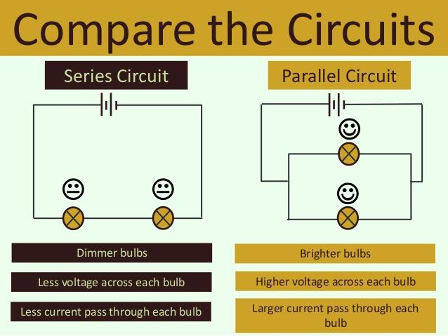
10 Explore IX In the last lessons, you examined energy transformation in series circuits. A series circuit has a single loop or path for charge to flow through. In this lesson, you will investigate parallel circuits. A parallel circuit has multiple paths for charge to flow through. Set Up Brightness Prediction Rank the Brightness of Each Set Up Brightness Observation Explain IIX 46. Compare your predictions to the evidence. Were your ideas supported by the evidence or has your thinking changed? 47. Why do you think the bulbs in the parallel circuit were brighter than the bulbs in the series circuit? 48. Why do you think the bulbs in the parallel circuit were about the same brightness as the single bulb? Compare the current in the parallel bulbs to the single series bulb. 49. Which circuit do you think will remove energy from the battery quicker? Why? 50. As the number of paths in a circuit increases, what do you think happens to the current in the circuit? 51. If the current increases as the number of paths increase, what must happen to the total resistance of the circuit? 10
11 Explore X Now you will take a closer look at the characteristics of series and parallel circuits. I am glad you noticed, in the third and fourth set-ups the single wire at the bottom of each picture should connect to the right side of the base at Y and not the middle of the wire that connects X and Y. Set Up Prediction Observation What will happen if bulb X is removed? Simply unscrew the bulb. What will happen if bulb X is removed? Simply unscrew the bulb. What will happen if bulb X is removed? Simply unscrew the bulb. What will happen if bulb X and Y are removed? Simply unscrew the bulbs. Explain IX 52. Compare your predictions to the evidence. Were your ideas supported by the evidence or has your thinking changed? 53. What happens to a series circuit if a bulb is removed? 54. What happens to a parallel circuit if a bulb is removed? 55. Summarize the differences between series and parallel circuits. 11
12 Explore XI Now you will make measurements of current in series and parallel circuits using an ammeter and a voltmeter. An ammeter measures current in units of amperes. An ampere is a measure of the number of charges/second passing by the meter. A voltmeter measures volts or the difference in energy carried by each charge at two different points in the circuit. Record and graph the ammeter measurements. Plot both data sets on the same grid Set Up I (series) Graph Use two 25 Ohm resistors Current Prediction (amperes) Current Measurement (amperes) Voltage (volts) Set Up II (parallel) Use two 25 Ohm resistors Current Prediction (amperes) Current Measurement (amperes) Voltage (volts) Explain X 56. Compare your predictions to the evidence. Were your ideas supported by the evidence or has your thinking changed? 57. As the voltage increases, what happens to the current in the circuit? 58. Compare the slopes for each set of data. Which circuit has a greater resistance? Explore XII 59. In this activity you and your group will draw a circuit diagram for a black box made up of lights, wires, batteries, and switches. You will use the Phet applets to create the circuits following teacher s example. It is called a black box because all of the wires and connections will be hidden. Other students can see the voltage source, the bulbs, and the switches. By unscrewing bulbs and flipping switches they need to draw possible circuit diagrams that would match their observations. We will do a walk- around where you and your group will have 3 minutes to explore each of the other groups circuits and to draw a circuit diagram you think will match the circuit your observed. After the big reveal we will see which group has the most circuits identified. What do you win? Bragging rights. Rules: No more than 5 bulbs of equal resistance. One battery No more than 5 switches. All bulbs, switches, and the battery are visible and in the top half of your circuit. 12


13 Read Summary Notes: 13
14 Power The rate of energy dissipation by a resistor in a simple circuit is defined by the following relationships (combining Ohm s Law with the basic power equation P=IV): P=IV=I 2 R= V 2 R The units used to measure the rate of energy dissipation are given below: Power = Joules second =Watts Another useful relationship in determining a rate of energy transformation is determined through: Energy Power =Force velocity= N m s = Joules second =Watts Since power is the change in energy over time, energy is the product of power and time. Energy = Power x time A bulbs brightness or any other electric appliance s output is based on the power dissipated by this particular resistor. Ex. A 20W bulb is brighter than a 10W bulb or a 1500W vacuum cleaner is stronger than a 500W vacuum cleaner. The cost of using electricity is based on the power of the appliance and how long it is being used. Ex. Using a 1000W microwave oven for 2 minutes uses twice the energy of using it for 1 minute and therefore also costs you twice as much. Problem Demonstrations: Resistance Resistance is the ability of a medium to restrict the flow of charge in a circuit. A resistor converts electric potential energy into heat. The physical properties of the medium, the temperature of the medium, and the physical dimensions of the medium define its resistance. Resistivity is the material specific constant used in the determination of resistance at a specific temperature. Table of Resistivities. PROBLEM The five resistors shown below have lengths and cross sectional areas indicated and are made of material with the same resistivity. Which has the greatest resistance? The relationship between resistance and the physical dimensions of the conductive medium is defined: R = ρ l A (at a specified temperature) where l represents the length of the conductor, A is its cross-sectional area, and (rho) is the resistivity of the material. PROBLEM Calculate the resistance at 20 C of an aluminum wire that is meter long and has a cross-sectional area of 1.00 x 10⁻³ square meter. SOLUTION We know from the table given above that aluminum has a resistivity of 2.65 x 10⁻⁸ Ω m. Therefore: R = ρ l A (at a specified temperature) =2.65x 10⁻⁸ Ωm 0.200m /1.00 x 10-3 m2 =5.30x 10⁻⁶ Ω 14
15 Current The SI unit of current is the ampere. current = q 1 coulomb 1 ampere = t second PROBLEM What is the electric current in a conductor if 240 coulombs of charge pass through it in 1.0 minute? SOLUTION We solve the problem by using the relation I = Qt and remembering that time must be measured in seconds. I= Q/t = 240 C/60. s = 4.0A Ohm s Law Ohm s law can be summarized by the following equation: Current = Voltage Resistance = Amperes = Volts Ohms(Ω) = I = V R This relationship is only valid for ohmic resistors that do not change resistance over a range of current values. In reality, as a resistor heats up, its resistance changes. PROBLEM Determine the resistance of resistor A and resistor B. R A =V/I = 5V/2.5a=2Ω R B =V/I = 5V/5a=1Ω If resistor A was connected in series with a 6 volt battery, what current would be measured in the resistor? I=V/R=6B/2Ω=3a Power The rate of energy dissipation by a resistor in a simple circuit is defined by the following relationships: P=IV=I 2 R= V 2 R The units used to measure the rate of energy dissipation are given below: Power = Joules second =Watts Another useful relationship in determining a rate of energy transformation is determined through: Power =Force velocity= N m s = Joules second =Watts PROBLEM 1989B3. A series circuit consists of a battery of negligible internal resistance, a variable resistor, and an electric motor of negligible resistance. The current in the circuit is 2 amperes when the resistance in the circuit is adjusted to 10 ohms. Under these conditions the motor lifts a l-kilogram mass vertically at a constant speed of 2 meters per second. a. Determine the electrical power that is i. dissipated in the resistor P=I 2 R=(2a) 2 (10Ω)=40watts ii. used by the motor in lifting the mass P=Fv=(1kg)(10m/s 2 )(2m/s)=20 watts iii. supplied by the battery 40 watts + 20 watts = 60 watts b. Determine the potential difference across i. the resistor P=IV V=P/I =(40watts)(2a)=20V ii. the motor P=IV V=P/I =(20watts)(2a)=10V iii. the battery V=Vdrop R + Vdrop Motor = 30V The resistor is now adjusted until the mass rises vertically at a constant speed of 3 meters per second. The voltage drop across the motor is proportional to the speed of the motor, and the current remains constant. c. Determine the voltage drop across the motor. V 3m/s = 1.5(10V) = 15 V d. Determine the new resistance in the circuit. 30V-15V=15V (15V)/(2a)=7.5Ω 15
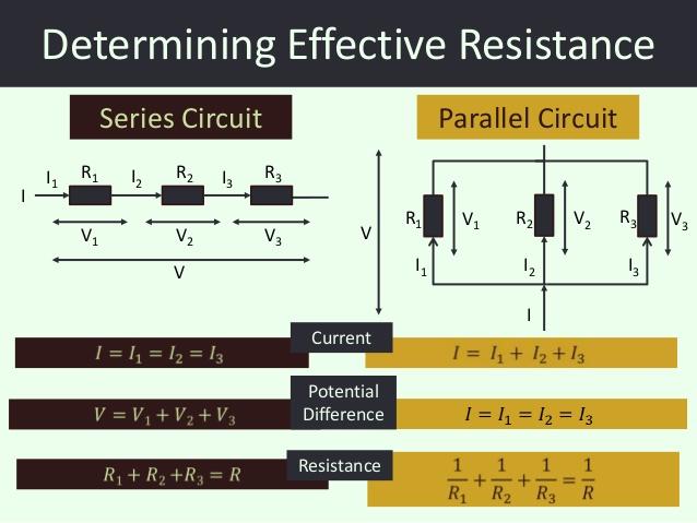
16 Resistors in Series When resistors are linked together in series in a circuit, the total effective resistance is the sum of the individual resistors. R s =R 1 +R 2 +R 3 Kirchoff s Loop Rule The sum of all of the changes in potential difference in a circuit is equal to zero. The voltage source (battery) provides an increase in potential, while the other circuit elements (resistors, motors, light bulbs) lower the potential. PROBLEM Examine the circuit below. a) Determine the total effective resistance of the circuit. R s=r 1+R 2+R 3 = 3Ω+6Ω+9Ω = 18Ω b) Determine the current in the circuit. I=V/R = 24V/18Ω=1.33a c) Determine the voltage drop across each resistor. V=IR V 12=(1.33a)(3Ω)=4V V 23=(1.33a)(6Ω)=8V V 34=(1.33a)(9Ω)=12V 0 = V source + V drop1 + V drop2 + V drop3 Resistors in Parallel When resistors are linked together in parallel, the total effective resistance is determined through the following relationship 1 = R p R 1 R 2 R 3 Kirchoff s Junction Rule The sum of all of the currents entering a junction equals the sum of the currents leaving a junction. PROBLEM a) Determine the total effective resistance of the circuit. 1/Rs=1/R 1+1/R 2+1/R 3 =[1/3Ω+1/6Ω+1/9Ω] -1 = 1.64Ω b) Determine the current in the circuit. I=V/R = 24V/1.64Ω=14.67a c) Determine the current in each resistor. I=V/R 24V/3Ω=8a 24V/6Ω=4a 24V/9Ω=2.67a (8a+4a+2.67a=14.6a) V source = V 1 = V 2 = V 3 Internal Resistance Real batteries have a certain resistance as a result of the physical and chemical properties of their construction. In certain problems this resistance must be included in the problem solving process. The internal resistance is treated as a normal resistor in series with the battery. The terminal voltage is the actual voltage the external circuit sees from the battery. The emf (electromotive force) is the voltage across the battery that has not been adjusted for the internal resistance. Problem A battery with an emf of 24 volts and an internal resistance of 1 ohm is connected to an external circuit as shown on the right. Determine each of the following: a) the equivalent resistance of the combination of the 4 ohm, 8 ohm, and 12 ohm resistors. [1/R 1+(1/(R 2+R 3))]-1 RP=[1/12Ω+(1/(4Ω+8Ω))] -1 R P=6Ω b)the current in the 5 ohm resistor I = V/R I=24V/(12Ω) = 2a c)the terminal voltage VAC, of the battery V AC = emf-ir internal = 24V-(2a)(1Ω)=22V d) the rate at which energy is dissipated in the 12 ohm resistor P=I 2 R P=(1a) 2 (12Ω)=12watts e) the magnitude of the potential difference VBC V BC=V terminal-ir 5Ω=22V-(2a)(5Ω)=12V f) the power delivered by the battery to the external circuit P=IV = (2a)(22V) = 44 watts 16
Electric Current & DC Circuits
 Electric Current & DC Circuits Circuits Click on the topic to go to that section Conductors Resistivity and Resistance Circuit Diagrams Measurement EMF & Terminal Voltage Kirchhoff's Rules Capacitors*
Insulators Non-metals are very good insulators; their electrons are very tightly bonded and cannot move.
 SESSION 11: ELECTRIC CIRCUITS Key Concepts Resistance and Ohm s laws Ohmic and non-ohmic conductors Series and parallel connection Energy in an electric circuit X-planation 1. CONDUCTORS AND INSULATORS
52 VOLTAGE, CURRENT, RESISTANCE, AND POWER
 52 VOLTAGE, CURRENT, RESISTANCE, AND POWER 1. What is voltage, and what are its units? 2. What are some other possible terms for voltage? 3. Batteries create a potential difference. The potential/voltage
Electric Current & DC Circuits How to Use this File Electric Current & DC Circuits Click on the topic to go to that section Circuits
 Slide 1 / 127 Slide 2 / 127 Electric Current & DC Circuits www.njctl.org Slide 3 / 127 How to Use this File Slide 4 / 127 Electric Current & DC Circuits Each topic is composed of brief direct instruction
Current Electricity. ScienceLinks 9, Unit 4 SciencePower 9, Unit 3
 Current Electricity ScienceLinks 9, Unit 4 SciencePower 9, Unit 3 Current Electricity The flow of negative charges (electrons) through conductors Watch the BrainPOPs: Electricity Current Electricity Activity:
Circuits. Electric Current & DC Circuits. Slide 1 / 127. Slide 2 / 127. Slide 3 / 127. Slide 4 / 127. Slide 5 / 127. Slide 6 / 127
 Slide 1 / 127 Slide 2 / 127 New Jersey Center for Teaching and Learning Electric Current & DC Circuits www.njctl.org Progressive Science Initiative This material is made freely available at www.njctl.org
CLASS X- ELECTRICITY
 Conductor- Insulator: Materia Materials through which electric current cannot pass are called insulators. Electric Circuit: A continuous a CLASS X- ELECTRICITY als through which electric current can pass
Clicker Session Currents, DC Circuits
 Clicker Session Currents, DC Circuits Wires A wire of resistance R is stretched uniformly (keeping its volume constant) until it is twice its original length. What happens to the resistance? 1) it decreases
Algebra Based Physics
 Page 1 of 105 Algebra Based Physics Electric Current & DC Circuits 2015-10-06 www.njctl.org Page 2 of 105 Electric Current & DC Circuits Circuits Conductors Resistivity and Resistance Circuit Diagrams
Chapter 17 Electric Current and Resistance Pearson Education, Inc.c
 Chapter 17 Electric Current and Resistance 2010 Pearson Education, Inc.c 1 Units of Chapter 17 Batteries and Direct Current Current and Drift Velocity Resistance and Ohm s Law Electric Power 2010 Pearson
Chapter 3: Electric Current And Direct-Current Circuits
 Chapter 3: Electric Current And Direct-Current Circuits 3.1 Electric Conduction 3.1.1 Describe the microscopic model of current Mechanism of Electric Conduction in Metals Before applying electric field
Physics Module Form 5 Chapter 2- Electricity GCKL 2011 CHARGE AND ELECTRIC CURRENT
 2.1 CHARGE AND ELECTRIC CURRENT Van de Graaf 1. What is a Van de Graaff generator? Fill in each of the boxes the name of the part shown. A device that produces and store electric charges at high voltage
AP Physics C - E & M
 Slide 1 / 27 Slide 2 / 27 AP Physics C - E & M Current, Resistance & Electromotive Force 2015-12-05 www.njctl.org Slide 3 / 27 Electric Current Electric Current is defined as the movement of charge from
CHAPTER 1 ELECTRICITY
 CHAPTER 1 ELECTRICITY Electric Current: The amount of charge flowing through a particular area in unit time. In other words, it is the rate of flow of electric charges. Electric Circuit: Electric circuit
10/14/2018. Current. Current. QuickCheck 30.3
 Current If QCurrent is the total amount of charge that has moved past a point in a wire, we define the current I in the wire to be the rate of charge flow: The SI unit for current is the coulomb per second,
physics 4/7/2016 Chapter 31 Lecture Chapter 31 Fundamentals of Circuits Chapter 31 Preview a strategic approach THIRD EDITION
 Chapter 31 Lecture physics FOR SCIENTISTS AND ENGINEERS a strategic approach THIRD EDITION randall d. knight Chapter 31 Fundamentals of Circuits Chapter Goal: To understand the fundamental physical principles
Question 3: How is the electric potential difference between the two points defined? State its S.I. unit.
 EXERCISE (8 A) Question : Define the term current and state its S.I unit. Solution : Current is defined as the rate of flow of charge. I = Q/t Its S.I. unit is Ampere. Question 2: Define the term electric
Electric Current. Chapter 17. Electric Current, cont QUICK QUIZ Current and Resistance. Sections: 1, 3, 4, 6, 7, 9
 Electric Current Chapter 17 Current and Resistance Sections: 1, 3, 4, 6, 7, 9 Whenever electric charges of like signs move, an electric current is said to exist The current is the rate at which the charge
Electromagnetism Checklist
 Electromagnetism Checklist Elementary Charge and Conservation of Charge 4.1.1A Convert from elementary charge to charge in coulombs What is the charge in coulombs on an object with an elementary charge
Preliminary Course Physics Module 8.3 Electrical Energy in the Home Summative Test. Student Name:
 Summative Test Student Name: Date: / / IMPORTANT FORMULAE I = Q/t V = I.R R S = R 1 + R 2 +.. 1/R P = 1/R 1 + 1/R 2 + P = V.I = I 2.R = V 2 /R Energy = V.I.t E = F/q Part A. Multiple Choice Questions 1-20.
CIRCUITS: Series & Parallel
 CIRCUITS: Series & Parallel Last Week s BIG IDEAS: Opposite charged objects attract Like charged objects repel Last Week s BIG IDEAS: The electrons are the loose particles that move to make things charged
Chapter 19. Electric Current, Resistance, and DC Circuit Analysis
 Chapter 19 Electric Current, Resistance, and DC Circuit Analysis I = dq/dt Current is charge per time SI Units: Coulombs/Second = Amps Direction of Electron Flow _ + Direction of Conventional Current:
Tactics Box 23.1 Using Kirchhoff's Loop Law
 PH203 Chapter 23 solutions Tactics Box 231 Using Kirchhoff's Loop Law Description: Knight/Jones/Field Tactics Box 231 Using Kirchhoff s loop law is illustrated Learning Goal: To practice Tactics Box 231
Circuits. Circuits. Electric Current & DC Circuits. current and circuits presentation March 22, How to Use this File.
 New Jersey Center for Teaching and Learning Electric Current & DC Circuits Progressive Science Initiative This material is made freely available at www.njctl.org and is intended for the non commercial
AP Physics C. Electric Circuits III.C
 AP Physics C Electric Circuits III.C III.C.1 Current, Resistance and Power The direction of conventional current Suppose the cross-sectional area of the conductor changes. If a conductor has no current,
This week. 3/23/2017 Physics 214 Summer
 This week Electrical Circuits Series or parallel that s the question. Current, Power and Energy Why does my laptop battery die? Transmission of power to your home Why do we have big transmission towers?
This week. 6/2/2015 Physics 214 Summer
 This week Electrical Circuits Series or parallel that s the question. Current, Power and Energy Why does my laptop battery die? Transmission of power to your home Why do we have big transmission towers?
Agenda for Today. Elements of Physics II. Resistance Resistors Series Parallel Ohm s law Electric Circuits. Current Kirchoff s laws
 Resistance Resistors Series Parallel Ohm s law Electric Circuits Physics 132: Lecture e 17 Elements of Physics II Current Kirchoff s laws Agenda for Today Physics 201: Lecture 1, Pg 1 Clicker Question
Electron Theory of Charge. Electricity. 1. Matter is made of atoms. Refers to the generation of or the possession of electric charge.
 Electricity Refers to the generation of or the possession of electric charge. There are two kinds of electricity: 1. Static Electricity the electric charges are "still" or static 2. Current Electricity
Electric Charge. Electric Charge ( q ) unbalanced charges positive and negative charges. n Units Coulombs (C)
 unbalanced charges positive and negative charges. n Units Coulombs (C)") Electric Charge Electric Charge ( q ) unbalanced charges positive and negative charges n Units Coulombs (C) Electric Charge How do objects become charged? Types of materials Conductors materials in which
Electric Charge Electric Charge ( q ) unbalanced charges positive and negative charges n Units Coulombs (C) Electric Charge How do objects become charged? Types of materials Conductors materials in which
(b) State the relation between work, charge and potential difference for an electric circuit.
 State the relation between work, charge and potential difference for an electric circuit.") Question Bank on Ch-Electricity 1. (a) Define the S.I unit of potential difference. (b) State the relation between work, charge and potential difference for an electric circuit. Calculate the potential
Question Bank on Ch-Electricity 1. (a) Define the S.I unit of potential difference. (b) State the relation between work, charge and potential difference for an electric circuit. Calculate the potential
Circuits-Ohm's Law. 1. Which graph best represents the relationship between the electrical power and the current in a resistor that obeys Ohm s Law?
 1. Which graph best represents the relationship between the electrical power and the current in a resistor that obeys Ohm s Law? 2. A potential drop of 50 volts is measured across a 250- ohm resistor.
ELECTRICITY. Prepared by: M. S. KumarSwamy, TGT(Maths) Page
 Page") ELECTRICITY 1. Name a device that helps to maintain a potential difference across a conductor. Cell or battery 2. Define 1 volt. Express it in terms of SI unit of work and charge calculate the amount of
ELECTRICITY 1. Name a device that helps to maintain a potential difference across a conductor. Cell or battery 2. Define 1 volt. Express it in terms of SI unit of work and charge calculate the amount of
For an electric current to flow between two points, two conditions must be met.
 ELECTROSTATICS LAB Electric Circuits For an electric current to flow between two points, two conditions must be met. 1. There must be a conducting path between the points along which the charges can move.
Use these circuit diagrams to answer question 1. A B C
 II Circuit Basics Use these circuit diagrams to answer question 1. B C 1a. One of the four voltmeters will read 0. Put a checkmark beside it. b. One of the ammeters is improperly connected. Put a checkmark
8. Electric circuit: The closed path along which electric current flows is called an electric circuit.
 GIST OF THE LESSON 1. Positive and negative charges: The charge acquired by a glass rod when rubbed with silk is called positive charge and the charge acquired by an ebonite rod when rubbed with wool is
LABORATORY 4 ELECTRIC CIRCUITS I. Objectives
 LABORATORY 4 ELECTRIC CIRCUITS I Objectives to be able to discuss potential difference and current in a circuit in terms of electric field, work per unit charge and motion of charges to understand that
Chapter 25 Current, Resistance, and Electromotive Force
 Chapter 25 Current, Resistance, and Electromotive Force Lecture by Dr. Hebin Li Goals for Chapter 25 To understand current and how charges move in a conductor To understand resistivity and conductivity
9. Which of the following is the correct relationship among power, current, and voltage?. a. P = I/V c. P = I x V b. V = P x I d.
 Name: Electricity and Magnetism Test Multiple Choice Identify the choice that best completes the statement. 1. Resistance is measured in a unit called the. a. ohm c. ampere b. coulomb d. volt 2. The statement
Which of the following is the SI unit of gravitational field strength?
 T5-2 [122 marks] 1. A cell is connected in series with a 2.0Ω resistor and a switch. The voltmeter is connected across the cell and reads 12V when the switch is open and 8.0V when the switch is closed.
Test Review Electricity
 Name: Date: 1. An operating television set draws 0.71 ampere of current when connected to a 120-volt outlet. Calculate the time it takes the television to consume 3.0 10 5 joules of electric energy. [Show
Current and Resistance
 Current and Resistance 1 Define the current. Understand the microscopic description of current. Discuss the rat at which the power transfer to a device in an electric current. 2 2-1 Electric current 2-2
Chapter 17. Current and Resistance. Sections: 1, 3, 4, 6, 7, 9
 Chapter 17 Current and Resistance Sections: 1, 3, 4, 6, 7, 9 Equations: 2 2 1 e r q q F = k 2 e o r Q k q F E = = I R V = A L R ρ = )] ( 1 [ o o T T + = α ρ ρ V I V t Q P = = R V R I P 2 2 ) ( = = C Q
Circuits. PHY2054: Chapter 18 1
 Circuits PHY2054: Chapter 18 1 What You Already Know Microscopic nature of current Drift speed and current Ohm s law Resistivity Calculating resistance from resistivity Power in electric circuits PHY2054:
Direct Current Circuits. February 18, 2014 Physics for Scientists & Engineers 2, Chapter 26 1
 Direct Current Circuits February 18, 2014 Physics for Scientists & Engineers 2, Chapter 26 1 Kirchhoff s Junction Rule! The sum of the currents entering a junction must equal the sum of the currents leaving
2/25/2014. Circuits. Properties of a Current. Conservation of Current. Definition of a Current A. I A > I B > I C B. I B > I A C. I C D. I A E.
 Circuits Topics: Current Conservation of current Batteries Resistance and resistivity Simple circuits 0.1 Electromotive Force and Current Conventional current is the hypothetical flow of positive charges
ELECTRIC CURRENT. Ions CHAPTER Electrons. ELECTRIC CURRENT and DIRECT-CURRENT CIRCUITS
 LCTRC CURRNT CHAPTR 25 LCTRC CURRNT and DRCTCURRNT CRCUTS Current as the motion of charges The Ampère Resistance and Ohm s Law Ohmic and nonohmic materials lectrical energy and power ons lectrons nside
Closed loop of moving charges (electrons move - flow of negative charges; positive ions move - flow of positive charges. Nucleus not moving)
") Unit 2: Electricity and Magnetism Lesson 3: Simple Circuits Electric circuits transfer energy. Electrical energy is converted into light, heat, sound, mechanical work, etc. The byproduct of any circuit
Unit 2: Electricity and Magnetism Lesson 3: Simple Circuits Electric circuits transfer energy. Electrical energy is converted into light, heat, sound, mechanical work, etc. The byproduct of any circuit
Look over Chapter 26 sections 1-7 Examples 3, 7. Look over Chapter 18 sections 1-5, 8 over examples 1, 2, 5, 8, 9,
 Look over Chapter 26 sections 1-7 Examples 3, 7 Look over Chapter 18 sections 1-5, 8 over examples 1, 2, 5, 8, 9, 1)How to find a current in a wire. 2)What the Current Density and Draft Speed are. 3)What
1) Two lightbulbs, one rated 30 W at 120 V and another rated 40 W at 120 V, are arranged in two different circuits.
 Two lightbulbs, one rated 30 W at 120 V and another rated 40 W at 120 V, are arranged in two different circuits.") 1) Two lightbulbs, one rated 30 W at 120 V and another rated 40 W at 120 V, are arranged in two different circuits. a. The two bulbs are first connected in parallel to a 120 V source. i. Determine the
1) Two lightbulbs, one rated 30 W at 120 V and another rated 40 W at 120 V, are arranged in two different circuits. a. The two bulbs are first connected in parallel to a 120 V source. i. Determine the
Materials Needed 1 D-Cell battery 6 6-inch pieces of wire 3 flashlight light bulbs 3 light bulb holders (optional)
") Experiment Module 3 Electric Circuits Objective/Introduction This experiment explores building simple circuits and testing Ohm s Law. Students will start lighting a simple light bulb. Then they will explore
Experiment Module 3 Electric Circuits Objective/Introduction This experiment explores building simple circuits and testing Ohm s Law. Students will start lighting a simple light bulb. Then they will explore
Current. I = ei e = en e Av d. The current, which is Coulomb s per second, is simply
 Current The current, which is Coulomb s per second, is simply I = ei e = en e Av d e is the charge is the electron! ne is the density of electrons! A is the cross sectional area of the wire! vd is the
Electric Power * OpenStax HS Physics. : By the end of this section, you will be able to:
 OpenStax-CNX module: m54446 1 Electric Power * OpenStax HS Physics This work is produced by OpenStax-CNX and licensed under the Creative Commons Attribution License 4.0 1 : By the end of this section,
Physics 7B-1 (A/B) Professor Cebra. Winter 2010 Lecture 2. Simple Circuits. Slide 1 of 20
 Professor Cebra. Winter 2010 Lecture 2. Simple Circuits. Slide 1 of 20") Physics 7B-1 (A/B) Professor Cebra Winter 2010 Lecture 2 Simple Circuits Slide 1 of 20 Conservation of Energy Density In the First lecture, we started with energy conservation. We divided by volume (making
Physics 7B-1 (A/B) Professor Cebra Winter 2010 Lecture 2 Simple Circuits Slide 1 of 20 Conservation of Energy Density In the First lecture, we started with energy conservation. We divided by volume (making
Electric charge is conserved the arithmetic sum of the total charge cannot change in any interaction.
 Electrostatics Electric charge is conserved the arithmetic sum of the total charge cannot change in any interaction. Electric Charge in the Atom Atom: Nucleus (small, massive, positive charge) Electron
PHY232 Spring 2008 Jon Pumplin (Original ppt courtesy of Remco Zegers) Direct current Circuits
 Direct current Circuits") PHY232 Spring 2008 Jon Pumplin http://www.pa.msu.edu/~pumplin/phy232 (Original ppt courtesy of Remco Zegers) Direct current Circuits So far, we have looked at systems with only one resistor PHY232 Spring
PHY232 Spring 2008 Jon Pumplin http://www.pa.msu.edu/~pumplin/phy232 (Original ppt courtesy of Remco Zegers) Direct current Circuits So far, we have looked at systems with only one resistor PHY232 Spring
Gr. 11 Physics Electricity
 Gr. 11 Physics Electricity This chart contains a complete list of the lessons and homework for Gr. 11 Physics. Please complete all the worksheets and problems listed under Homework before the next class.
EXPERIMENT 12 OHM S LAW
 EXPERIMENT 12 OHM S LAW INTRODUCTION: We will study electricity as a flow of electric charge, sometimes making analogies to the flow of water through a pipe. In order for electric charge to flow a complete
Physics 1214 Chapter 19: Current, Resistance, and Direct-Current Circuits
 Physics 1214 Chapter 19: Current, Resistance, and Direct-Current Circuits 1 Current current: (also called electric current) is an motion of charge from one region of a conductor to another. Current When
ConcepTest Clicker Questions. Chapter 26 Physics: for Scientists & Engineers with Modern Physics, 4th edition Giancoli
 ConcepTest Clicker Questions Chapter 26 Physics: for Scientists & Engineers with Modern Physics, 4th edition Giancoli 2008 Pearson Education, Inc. This work is protected by United States copyright laws
Class 8. Resistivity and Resistance Circuits. Physics 106. Winter Press CTRL-L to view as a slide show. Class 8. Physics 106.
 and Circuits and Winter 2018 Press CTRL-L to view as a slide show. Last time we learned about Capacitance Problems Parallel-Plate Capacitors Capacitors in Circuits Current Ohm s Law and Today we will learn
Lesson Plan: Electric Circuits (~130 minutes) Concepts
 Concepts") Lesson Plan: Electric Circuits (~130 minutes) Concepts 1. Electricity is the flow of electric charge (electrons). 2. Electric Charge is a property of subatomic particles. 3. Current is the movement of
Lesson Plan: Electric Circuits (~130 minutes) Concepts 1. Electricity is the flow of electric charge (electrons). 2. Electric Charge is a property of subatomic particles. 3. Current is the movement of
Topic 5.2 Heating Effect of Electric Currents
 Topic 5.2 Heating Effect of Electric Currents Kari Eloranta 2017 Jyväskylän Lyseon lukio International Baccalaureate February 14, 2017 Topic 5.2 Heating Effect of Electric Currents In subtopic 5.2 we study
ConcepTest PowerPoints
 ConcepTest PowerPoints Chapter 19 Physics: Principles with Applications, 6 th edition Giancoli 2005 Pearson Prentice Hall This work is protected by United States copyright laws and is provided solely for
Nama :.. Kelas/No Absen :
 Nama :.. Kelas/No Absen : TASK 2 : CURRENT AND RESISTANCE 1. A car battery is rated at 80 A h. An ampere-hour is a unit of: A. power B. energy C. current D. charge E. force 2. Current has units: A. kilowatt-hour
Physics 214 Spring
 Lecture 23 March 4 2016 The elation between Voltage Differences V and Voltages V? Current Flow, Voltage Drop on esistors and Equivalent esistance Case 1: Series esistor Combination and esulting Currents
Physics 212 Midterm 2 Form A
 1. A wire contains a steady current of 2 A. The charge that passes a cross section in 2 s is: A. 3.2 10-19 C B. 6.4 10-19 C C. 1 C D. 2 C E. 4 C 2. In a Physics 212 lab, Jane measures the current versus
11. ELECTRIC CURRENT. Questions and Answers between the forces F e and F c. 3. Write the difference between potential difference and emf. A.
 CLSS-10 1. Explain how electron flow causes electric current with Lorentz-Drude theory of electrons?. Drude and Lorentz, proposed that conductors like metals contain a large number of free electrons while
Chapter 16. Current and Drift Speed. Electric Current, cont. Current and Drift Speed, cont. Current and Drift Speed, final
 Chapter 6 Current, esistance, and Direct Current Circuits Electric Current Whenever electric charges of like signs move, an electric current is said to exist The current is the rate at which the charge
Chapter 25 Electric Currents and Resistance. Copyright 2009 Pearson Education, Inc.
 Chapter 25 Electric Currents and Resistance 25-4 Resistivity Example 25-5: Speaker wires. Suppose you want to connect your stereo to remote speakers. (a) If each wire must be 20 m long, what diameter copper
College Physics B - PHY2054C
 Power College - PHY2054C and 09/15/2014 My Office Hours: Tuesday 10:00 AM - Noon 206 Keen Building PHY2054C Power First Mini-Exam this week on Wednesday!! Location: UPL 101, 10:10-11:00 AM Exam on chapters
Dynamic Electricity. All you need to be an inventor is a good imagination and a pile of junk. -Thomas Edison
 Dynamic Electricity All you need to be an inventor is a good imagination and a pile of junk. -Thomas Edison Review Everything is made of atoms which contain POSITIVE particles called PROTONS and NEGATIVE
CHAPTER 16,18,19 TEST REVIEW
 AP PHYSICS Name: Period: Date: Points: 58 Score: IB Curve: DEVIL PHYSICS BADDEST CLASS ON CAMPUS 50 Multiple Choice 45 Single Response 5 Multi-Response Free Response 3 Short Free Response 2 Long Free Response
Chapter 20 Electric Circuits
 Chapter 0 Electric Circuits Chevy olt --- Electric vehicle of the future Goals for Chapter 9 To understand the concept of current. To study resistance and Ohm s Law. To observe examples of electromotive
Notes on Electricity (Circuits)
") A circuit is defined to be a collection of energy-givers (batteries) and energy-takers (resistors, light bulbs, radios, etc.) that form a closed path (or complete path) through which electrical current
A circuit is defined to be a collection of energy-givers (batteries) and energy-takers (resistors, light bulbs, radios, etc.) that form a closed path (or complete path) through which electrical current
Physics Module Form 5 Chapter 2- Electricity GCKL 2011 CHARGE AND ELECTRIC CURRENT
 2.1 CHARGE AND ELECTRIC CURRENT Van de Graaf 1. What is a Van de Graaff generator? Fill in each of the boxes the name of the part shown. A device that... and... at high voltage on its dome. dome 2. You
Direct-Current Circuits. Physics 231 Lecture 6-1
 Direct-Current Circuits Physics 231 Lecture 6-1 esistors in Series and Parallel As with capacitors, resistors are often in series and parallel configurations in circuits Series Parallel The question then
ConcepTest PowerPoints
 ConcepTest PowerPoints Chapter 16 Physics: Principles with Applications, 7 th edition Giancoli 2014 Pearson Education, Inc. This work is protected by United States copyright laws and is provided solely
ΔV of battery. = ε - Ir or εmf = I(R+r) (for this particular series circuit) March 04, Emf and internal resistance. Emf and internal resistance
 (for this particular series circuit) March 04, Emf and internal resistance. Emf and internal resistance") Emf and internal resistance Emf and internal resistance ΔV of battery = ε - Ir or εmf = I(R+r) (for this particular series circuit) As the current in the circuit increases the voltage, supplied to the
Emf and internal resistance Emf and internal resistance ΔV of battery = ε - Ir or εmf = I(R+r) (for this particular series circuit) As the current in the circuit increases the voltage, supplied to the
Flow Rate is the NET amount of water passing through a surface per unit time
 Electric Current An Analogy Water Flow in a Pipe H 2 0 gallons/minute Flow Rate is the NET amount of water passing through a surface per unit time Individual molecules are bouncing around with speeds of
DEVIL PHYSICS THE BADDEST CLASS ON CAMPUS IB PHYSICS
 DEL PHYSCS THE BADDEST CLASS ON CAMPUS B PHYSCS TSOKOS LESSON 5-4: ELECTRC CURRENT AND ELECTRC RESSTANCE Reading Activity Questions? Objectives By the end of this class you should be able to: Q State the
A free web support in Education. Internal resistance of the battery, r = 3 Ω. Maximum current drawn from the battery = I According to Ohm s law,
 Exercises Question 3.1: The storage battery of a car has an emf of 12 V. If the internal resistance of the battery is 0.4Ω, what is the maximum current that can be drawn from the battery? Answer 3.1: Emf
PhysicsAndMathsTutor.com
 Electricity May 02 1. The graphs show the variation with potential difference V of the current I for three circuit elements. PhysicsAndMathsTutor.com When the four lamps are connected as shown in diagram
Chapter 7 Direct-Current Circuits
 Chapter 7 Direct-Current Circuits 7. Introduction... 7. Electromotive Force... 7.3 Resistors in Series and in Parallel... 4 7.4 Kirchhoff s Circuit Rules... 6 7.5 Voltage-Current Measurements... 8 7.6
Parallel Resistors (32.6)
") Parallel Resistors (32.6) Resistors connected at both ends are called parallel resistors The important thing to note is that: the two left ends of the resistors are at the same potential. Also, the two
Parallel Resistors (32.6) Resistors connected at both ends are called parallel resistors The important thing to note is that: the two left ends of the resistors are at the same potential. Also, the two
Electrical Circuits. Winchester College Physics. makptb. c D. Common Time man. 3rd year Revision Test
 Name... Set... Don.... manner~ man makptb Winchester College Physics 3rd year Revision Test Electrical Circuits Common Time 2011 Mark multiple choice answers with a cross (X) using the box below. I A B
Electricity. Prepared by Juan Blázquez, Alissa Gildemann. Electric charge is a property of all objects. It is responsible for electrical phenomena.
 Unit 11 Electricity 1. Electric charge Electric charge is a property of all objects. It is responsible for electrical phenomena. Electrical phenomena are caused by the forces of attraction and repulsion.
Lab 8 Simple Electric Circuits
 Lab 8 Simple Electric Circuits INTRODUCTION When we talk about the current in a river, we are referring to the flow of water. Similarly, when we refer to the electric current in a circuit, we are talking
General Physics (PHYC 252) Exam 4
 Exam 4") General Physics (PHYC 5) Exam 4 Multiple Choice (6 points). Circle the one best answer for each question. For Questions 1-3, consider a car battery with 1. V emf and internal resistance r of. Ω that is
General Physics (PHYC 5) Exam 4 Multiple Choice (6 points). Circle the one best answer for each question. For Questions 1-3, consider a car battery with 1. V emf and internal resistance r of. Ω that is
Parallel Resistors (32.6)
") Parallel Resistors (32.6) Resistors connected at both ends are called parallel resistors Neil Alberding (SFU Physics) Physics 121: Optics, Electricity & Magnetism Spring 2010 1 / 1 Parallel Resistors (32.6)
Parallel Resistors (32.6) Resistors connected at both ends are called parallel resistors Neil Alberding (SFU Physics) Physics 121: Optics, Electricity & Magnetism Spring 2010 1 / 1 Parallel Resistors (32.6)
Power lines. Why do birds sitting on a high-voltage power line survive?
 Power lines At large distances, the resistance of power lines becomes significant. To transmit maximum power, is it better to transmit high V, low I or high I, low V? (a) high V, low I (b) low V, high
Physics 142 Steady Currents Page 1. Steady Currents
 Physics 142 Steady Currents Page 1 Steady Currents If at first you don t succeed, try, try again. Then quit. No sense being a damn fool about it. W.C. Fields Electric current: the slow average drift of
Ohm s Law Book page Syllabus 2.10
 Ohm s Law Book page 85 87 Syllabus 2.10 What s wrong with this circuit diagram? Task 2 Sketch a simple series circuit containing a cell and a bulb. On your circuit diagram, show an ammeter and voltmeter
Protons = Charge Electrons = Charge Neutrons = Charge. When Protons = Electrons, atoms are said to be ELECTRICALLY NEUTRAL (no net charge)
") QUICK WRITE: For 2 minutes, write the three parts of an atom and what their charges are. Explain what creates an electric charge (positive or negative) on something. Rules - You MUST write for the entire
QUICK WRITE: For 2 minutes, write the three parts of an atom and what their charges are. Explain what creates an electric charge (positive or negative) on something. Rules - You MUST write for the entire
Review. Multiple Choice Identify the letter of the choice that best completes the statement or answers the question.
 Review Multiple Choice Identify the letter of the choice that best completes the statement or answers the question. 1. When more devices are added to a series circuit, the total circuit resistance: a.
T U T O R I A L : A M O D E L F O R C I R C U I T S
 South Pasadena Physics Name 10 Circuits Period Date T U T O R I A L : A M O D E L F O R C I R C U I T S Tutorial Instructions This Tutorial contains Activities and Exercises. Activities: These are intended
A Review of Circuitry
 1 A Review of Circuitry There is an attractive force between a positive and a negative charge. In order to separate these charges, a force at least equal to the attractive force must be applied to one
Chapter 21 Electric Current and Direct- Current Circuits
 Chapter 21 Electric Current and Direct- Current Circuits 1 Overview of Chapter 21 Electric Current and Resistance Energy and Power in Electric Circuits Resistors in Series and Parallel Kirchhoff s Rules
Science Olympiad Circuit Lab
 Science Olympiad Circuit Lab Key Concepts Circuit Lab Overview Circuit Elements & Tools Basic Relationships (I, V, R, P) Resistor Network Configurations (Series & Parallel) Kirchhoff s Laws Examples Glossary
Name Date Time to Complete. NOTE: The multimeter s 10 AMP range, instead of the 300 ma range, should be used for all current measurements.
 Name Date Time to Complete h m Partner Course/ Section / Grade Complex Circuits In this laboratory you will continue your exploration of dc electric circuits with a steady current. The circuits will be