Lecture Set 8 Induction Machines
|
|
|
- Paul Hawkins
- 5 years ago
- Views:
Transcription
1 Lecture Set 8 Induction Machine S.D. Sudhoff Spring 2018
2 Reading Chapter 6, Electromechanical Motion Device, Section ,
3 Sample Application Low Power: Shaded pole machine (mall fan) Permanent Split Capacitor Machine (Reidential HVAC) Medium Power: Indutrial HVAC Pump Vehicle Propulion Drive Application High Power: Ship, Train Propulion Wind Power Generation 3
4 Characteritic The Good The Bad The Ugly 4
5 Type of IM Machine Wound Rotor Squirrel Cage Solid Rotor 5


6 1.5 MW Induction Generator 6

7 RPM 7

8 RPM 8


9 RPM (Stator) Spring 2010 ECE321 9


10 RPM (Rotor) Spring 2010 ECE321 10
11 Two-Phae IM 11
12 Stator MMF 12
13 Stator MMF 13
14 Stator MMF 14
15 Stator MMF 15
16 Stator MMF 16
17 Stator MMF 17
18 Rotor MMF 18
19 Rotor MMF 19
20 Rotor MMF 20
21 Rotor MMF 21
22 Rotor MMF 22
23 Rotor MMF 23
24 Comparion of MMF A viewed from tator A viewed from rotor 24
25 IM Torque Production 25
26 Our Analyi Machine Variable Model Referred Machine Variable Model QD Model Steady-State Model 26
27 Machine Variable Model Voltage equation v ab = r i ab + pλ v = r i + pλ abr r abr abr ab Flux Linkage Equation λab L Lr iab = T abr ( r ) λ L Lr iabr Inductance Matrice L L L r Ll + Lm 0 = 0 Ll L + m Llr + Lmr 0 = 0 Llr + L mr r coθr inθr = Lr inθr coθ r Torque equation P Te = Lr [( iaiar + ibibr )inθr 2 + (i i i i )co θ ] a br b ar r 27
28 Referred Machine Variable Model Referral of variable N i i r abr = abr N N v abr = v abr Nr N λ abr = λ abr Nr Voltage equation v ab = r i ab v abr = rr i abr + pλ abr 2 N r r = rr N r + pλ ab Flux linkage equation λab L L r iab = λ T abr ( Lr ) L r i abr L lr + Lm 0 L r = 0 L lr + L m L r = N coθr Lr = Lm N r inθr Torque equation T e P = L 2 m [( i a ar + (i i i + i a br b br i i b ar )inθ i r )coθ ] inθr coθ r r 28
29 QD Model 29
30 Phaor Model P 2 Torque: T = 2 L Re[ ji I ] e m ~ ~ * a ar 30
31 31 Machine Variable IM Model Voltage Equation Voltage Equation dt d i r v a a a λ + = dt d i r v b b b λ + = dt d i r v ar ar r ar λ + = dt d i r v br br r br λ + = abr abr r abr ab ab ab p p λ λ + = + = i r v i r v ] [ ) ( b a T ab f f = f ] [ ) ( br ar T abr f f = f
32 Machine Variable Machine Model Flux Linkage Equation In Scalar Form λ a = L i + L i + L i + aa a ab b aar ar L abr i br λ b = L i + L i + L i + ba a bb b bar ar L bbr i br λ ar = L i + L i + L i + ara a arb b arar ar L arbr i br λ br = L i + L i + L i + bra a brb b brar ar L brbr i br 32
33 Machine Variable Machine Model Flux Linkage Equation In Matrix-Vector Form Or λ λ λ λ ab abr ab abr = L i + L r ab T ab r = ( L ) i + L = L ( L r ) T i abr L L r r i r abr i i ab abr 33
34 Machine Variable Model Flux Linkage Equation Derivation of Magnetizing Inductance 34
35 Machine Variable Model Flux Linkage Equation Derivation of Magnetizing Inductance (Cont) 35
36 Machine Variable Model Flux Linkage Equation Derivation of Magnetizing Inductance (Cont) 36
37 Machine Variable Model Flux Linkage Equation Derivation of Magnetizing Inductance (Cont) 37
38 Machine Variable Model Flux Linkage Equation Derivation of Magnetizing Inductance (Cont) 38
39 Summary Machine Variable Model Flux Linkage Equation L 0 = 0 L L L = I Lrr 0 Lr = = Lrr L I 0 rr L = r L r coθr inθr inθr coθ r 39
40 Where Machine Variable Model Flux Linkage Equation L = L + rr l L = L + L L L m mr r = lr 2 N = R N = R N r R m 2 r m N m L L m mr 40
41 Let tart with Machine Variable Model Torque Equation λ λ ab abr = L ( L r ) T L L r r i i ab abr 41
42 Machine Variable Model Torque Equation 42
43 Machine Variable Model Torque Equation 43
44 Referred Machine Variable Model Why?? 44
45 Referred Machine Variable Model Flux Linkage Equation Starting Point λ λ ab abr = L ( L r ) T L L r r i i ab abr L 0 = 0 L L L = I Lrr 0 Lr = = Lrr L I 0 rr L = r L r coθr inθr inθr coθ r 45
46 Referred Machine Variable Model Flux Linkage Equation 46
47 Referred Machine Variable Model Flux Linkage Equation 47
48 48 Referred Machine Variable Model Flux Linkage Equation Reult Where = abr ab r T r r abr ab i i L L L L ) ( λ λ = = rr rr r r r L L N N L L m lr mr r lr rr L L L N N L L + = + = 2 = = r r r r m r r r L N N θ θ θ θ co in in co L L
49 Referred Machine Variable Model Voltage Equation Start with v v ab abr = = r r r i i ab abr + + pλ pλ ab abr 49
50 Referred Machine Variable Model Voltage Equation Finally, we get Where v v ab abr = = r r i r i ab abr + + pλ pλ ab abr r r = N N r 2 r r 50
51 Referred Machine Variable Model It can be hown that Torque Equation T e = P 2 L m [( i a i ar + i b i br )inθ + ( i i i i r a br b ar )coθ ] r 51
52 52 Next Step: Stationary Reference Frame Stator tranformation Rotor tranformation = b a d q f f f f ab qd f f = K qd ab f K f 1 ) ( = = br ar r r r r dr qr f f f f θ θ θ θ co in in co abr r qdr f K f = qdr r abr f K f = 1 ) (
53 Next Step: Stationary Reference Frame 53
54 Geometrical Interpretation 54
55 Tranformation of Voltage Equation 55
56 Tranformation of Voltage Equation 56
57 Tranformation of Voltage Equation 57
58 Tranformation of Voltage Equation 58
59 Tranformation of Voltage Equation Thi yield qdr v qd r = r i qdr qd r + pλ dqr qd v = r i ωλ + pλ λ = [ λ λ ] T dqr dr qr qdr 59
60 Tranformation of Flux Linkage Equation Recall λ ab = L i + L i ab r abr λ abr = ' r ab + L rri abr L T i 60
61 Tranformation of Flux Linkage Equation 61
62 Tranformation of Flux Linkage Equation 62
63 Tranformation of Flux Linkage Equation 63
64 Tranformation of Flux Linkage Equation Thi yield λ qd = L qd i + L i m qdr λ qdr = L m i qd + L ' rr i qdr L L ' rr = = L L l ' lr + + L L m m 64
65 Tranformation of the Torque Equation Start with T P in co T θr θr = L i 2 co θr in θ i r e r ab abr 65
66 Tranformation of the Torque Equation 66
67 Tranformation of the Torque Equation 67
68 Tranformation of the Torque Equation Finally, we get P T e = Lm ( iqidr idi 2 qr Which can be hown to be equal to P ' T e = ( λqr i dr λ dri 2 P Te = ( λdi q λqi 2 qr d ) ) ) 68
69 QD Equivalent Circuit 69
70 QD Equivalent Circuit 70
71 QD Equivalent Circuit 71
72 Comment on QD Machine When i it valid? What i it ued for? 72
73 Balanced Steady-State Operation Steady-tate form We can how F = 2F co[ ω t + θ (0)] a e ef F = 2F in[ ω t + θ (0)] b e ef ~ ~ jθef Fq = Fa = Fe ~ Fd = Fb = ( jfe ~ ~ F = jf (0) ~ jθef (0) q d ) 73
74 Balanced Steady-State Operation 74
75 Balanced Steady-State Operation 75
76 Balanced Steady-State Operation Rotor relationhip F = 2F co[( ω ω ) t + θ (0)] ar r e r erf F = 2F in[( ω ω ) t + θ (0)] br r e r erf We can how ~ ~ F = Far ~ ~ F = F ~ ~ F = jf qr dr qr br dr 76
77 Balanced Steady-State Operation 77
78 Balanced Steady-State Operation 78
79 Balanced Steady-State Operation 79
80 Balanced Steady-State Phaor Equivalent Circuit (2-Phae) P 2 Torque: T = 2 L Re[ ji I ] e m ~ ~ * a ar 80
81 Balanced Steady-State Phaor Equivalent Circuit (2-Phae) Voltage Equation ~ ~ ~ ~ V = ( r + jω L ) I + jω L ( I + I a ~ V ar rr = + e e l jω L ' lr a ~ I ar + e e m jω L m a ~ ( I a ar ~ + I ar ) ) Slip Torque ω e ω = r ω P ~ ~ T e = 2 L m Re[ ji a I 2 e * ar ] 81
82 Derivation of Balanced Steady-State Phaor Equivalent Circuit 82
83 Derivation of Balanced Steady-State Phaor Equivalent Circuit 83
84 Derivation of Balanced Steady-State Phaor Equivalent Circuit 84
85 Derivation of Balanced Steady-State Phaor Equivalent Circuit 85
86 Derivation of Balanced Steady-State Phaor Equivalent Circuit 86
87 Chief Problem with Model Magnetizing Saturation Leakage Saturation Ditributed Sytem Effect Thermal Effect 87
88 Balanced Steady-State Phaor Equivalent Circuit (3-Phae) Where T e = 3 P L 2 M ~ Re[ ji * a ~ I ar ] L M = 3 2 L m 88
89 Delta Connected Machine 89
90 Wye Connected Machine 90
91 Typical Operating Situation Utility grid Fixed voltage, fixed frequency voltage ource Inverter (power electronic control) Voltage ource baed inverter (variable voltage, variable frequency) Volt-per-hertz control Current ource baed inverter (variable current, variable frequency) Maximum torque per amp control Field-oriented control Direct torque control 91
92 Derivation of Rotor Current 92
93 Torque for a Given Stator Current We can how T e = P N 2 2 ( r ) r 2 ω LM I + ( ω L rr 2 ) r 2 r 93
94 Torque for a Given Stator Current 94
95 Torque for a Given Stator Current 95
96 Torque for a Given Stator Current 96
97 Operation from Current Source Machine Parameter 460 V, l-l, rm; rpm Stator reitance: 72.5 mω Rotor reitance: 41.3 mω Stator and referred rotor leakage: 1.32 mh Magnetizing Inductance: 30.1 mh Operating Condition Armature current: 50 A, rm Frequency: 60 Hz 97
98 Current Source Torque - Speed ( ) T e ω ri ω ri
99 99 Maximum Torque Per Amp Control (Operation from Current Source) Control Summary To how thi, tart with rr M rr r e r L NP L r T I + = * ) ) ( ( 2 ω ω rr r L r = ω ) ( ) ( 2 rr r r M e L r r I L P N T + = ω ω
100 Maximum Torque Per Amp Control (Operation from Current Source) 100
101 Maximum Torque Per Amp Control (Operation from Current Source) 101
102 Maximum Torque Per Amp Control (Operation from Current Source) 102
103 MTPA Control Example Conider the 50 Hp example Suppoe we want 200 Nm at a peed of 1000 rpm Compute the magnitude of the a-phae current, A Compute the required voltage Compute the efficiency 103
104 MTPA Control Example 104
105 MTPA Control Example 105
106 MTPA Control Example 106
107 Operation From Voltage Source: Prediction of Stator Current 107
108 Operation from Fixed Voltage Source: Example 1 Conider our 50 Hp machine Fed from 460 V l-l rm ource Load torque of 200 Nm Objective: Compute peed and current 108
109 Steady-State Operating Point ( ) 300 T e V, ω e, ω ri T L ω ri, ω ri
110 Steady-State Operating Point 110
111 Operation from Fixed Voltage Source: Example 2 Conider our 50 Hp machine Fed from 460 V l-l rm, 60 Hz ource Let look at machine propertie veru peed 111
112 Current v Speed ( ) (,, ω ri, r ) r0 (,, ω ri, r ) rb I a V, ω e, ω ri, r r I a V ω e I a V ω e ω ri
113 Torque v Speed ( ) (,, ω ri, r ) r0 ( ) T e V, ω e, ω ri, r r 300 T e V ω e T e V, ω e, ω ri, r rb ω ri
114 Efficiency v Speed ( ) (,, ω ri, r ) r0 ( ) η V, ω e, ω ri, r r η V ω e 0.6 η V, ω e, ω ri, r rb ω ri
115 Efficiency v Output Power ( ) (,, ω ri, r ) r0 ( ) η V, ω e, ω ri, r r 0.6 η V ω e η V, ω e, ω ri, r rb ( ) P out( V, ω e, ω ri, r ) r0 ( ) 0 P out V, ω e, ω ri, r r,, P out V, ω e, ω ri, r rb
116 Parameter Identification DC Tet 116
117 Parameter Identification Blocked Rotor Tet 117
118 Parameter Identification Blocked Rotor Tet 118
119 Parameter Identification No Load Tet 119
120 Volt Per Hertz Control The idea: 120
121 Volt Per Hertz Control The idea: 121
122 Volt Per Hertz Control ( ) (, ω ri ) (, ω ri ) (, ω ri ) T e ω eb, ω ri T e ω eb 0.75 T e ω eb 0.5 T e ω eb ω ri
Control of Wind Turbine Generators. James Cale Guest Lecturer EE 566, Fall Semester 2014 Colorado State University
 Control of Wind Turbine Generators James Cale Guest Lecturer EE 566, Fall Semester 2014 Colorado State University Review from Day 1 Review Last time, we started with basic concepts from physics such as
Overview: Induction Motors. Review Questions. Why the Rotor Moves: Motor Speed
 Overview: nduction Motor Motor operation & Slip Speed-torque relationhip Equivalent circuit model Tranformer Motor efficiency Starting induction motor Smith College, EGR 35 ovember 5, 04 Review Quetion
INDUCTION MOTOR MODEL AND PARAMETERS
 APPENDIX C INDUCTION MOTOR MODEL AND PARAMETERS C.1 Dynamic Model of the Induction Motor in Stationary Reference Frame A three phase induction machine can be represented by an equivalent two phase machine
Overview Electrical Machines and Drives
 Overview Electrical Machine and Drive 7-9 1: Introduction, Maxwell equation, magnetic circuit 11-9 1.-3: Magnetic circuit, Princile 14-9 3-4.: Princile, DC machine 18-9 4.3-4.7: DC machine and drive 1-9
Massachusetts Institute of Technology Department of Electrical Engineering and Computer Science Electric Machines
 Massachusetts Institute of Technology Department of Electrical Engineering and Computer Science 6.685 Electric Machines Problem Set 10 Issued November 11, 2013 Due November 20, 2013 Problem 1: Permanent
Synchronous Machines - Structure
 Synchronou Machine - Structure Synchronou Machine - Structure rotate at contant peed. primary energy converion device of the word electric power ytem. both generator and motor operation can draw either
Basic parts of an AC motor : rotor, stator, The stator and the rotor are electrical
 INDUCTION MOTO 1 CONSTUCTION Baic part of an AC motor : rotor, tator, encloure The tator and the rotor are electrical circuit that perform a electromagnet. CONSTUCTION (tator) The tator - tationary part
Chapter 5 Three phase induction machine (1) Shengnan Li
 Shengnan Li") Chapter 5 Three phase induction machine (1) Shengnan Li Main content Structure of three phase induction motor Operating principle of three phase induction motor Rotating magnetic field Graphical representation
Chapter 5 Three phase induction machine (1) Shengnan Li Main content Structure of three phase induction motor Operating principle of three phase induction motor Rotating magnetic field Graphical representation
Section Induction motor drives
 Section 5.1 - nduction motor drive Electric Drive Sytem 5.1.1. ntroduction he AC induction motor i by far the mot widely ued motor in the indutry. raditionally, it ha been ued in contant and lowly variable-peed
Equivalent Circuits with Multiple Damper Windings (e.g. Round rotor Machines)
") Equivalent Circuits with Multiple Damper Windings (e.g. Round rotor Machines) d axis: L fd L F - M R fd F L 1d L D - M R 1d D R fd R F e fd e F R 1d R D Subscript Notations: ( ) fd ~ field winding quantities
Equivalent Circuits with Multiple Damper Windings (e.g. Round rotor Machines) d axis: L fd L F - M R fd F L 1d L D - M R 1d D R fd R F e fd e F R 1d R D Subscript Notations: ( ) fd ~ field winding quantities
Induction Motor Drive
 Induction Motor Drive 1. Brief review of IM theory.. IM drive characteritic with: Variable input voltage Variable rotor reitance Variable rotor power Variable voltage and variable frequency, VVVF drive
Lecture 1: Induction Motor
 1 / 22 Lecture 1: Induction Motor ELEC-E8402 Control of Electric Drives and Power Converters (5 ECTS) Marko Hinkkanen Aalto University School of Electrical Engineering Spring 2016 2 / 22 Learning Outcomes
60 p. 2. A 200hp 600V, 60 Hz 3-phase induction motor has start code F. What line current should be expected at starting? 4 marks.
 EE 004 Final Solution : Thi wa a hr exam. A 60 Hz 4 pole -phae induction motor rotate at 740rpm. a) What i the lip? mark b) What i the peed o rotation o the rotor magnetic ield (in rpm)? mark The motor
Steady State Modeling of Doubly Fed Induction Generator
 Steady State Modeling of Douly Fed Induction Generator Bhola Jha 1, Dr. K. R. M Rao 2 1 Dept. of Electrical Engg., G. B. Pant Engg. College, Pauri-Garhwal, India 2 Dept. of Electrical Engg., M. J. College
BASIC INDUCTION MOTOR CONCEPTS
 INDUCTION MOTOS An induction motor ha the ame phyical tator a a ynchronou machine, with a different rotor contruction. There are two different type of induction motor rotor which can be placed inide the
ECE 325 Electric Energy System Components 6- Three-Phase Induction Motors. Instructor: Kai Sun Fall 2015
 ECE 35 Electric Energy Sytem Component 6- Three-Phae Induction Motor Intructor: Kai Sun Fall 015 1 Content (Material are from Chapter 13-15) Component and baic principle Selection and application Equivalent
EE595S : Class Lecture Notes Parameter Identification and Maximum Torque Per Amp Control Algorithm
 EE595S : Class Lecture Notes Parameter Identification and Maximum Torque Per Amp Control Algorithm Outline GA based AQDM Characterization Procedure MTPA Control strategy AMTPA Control Strategy 2 Alternate
Performance Improvement of Direct Torque Controlled Interior Permanent Magnet Synchronous Motor Drive by Considering Magnetic Saturation
 Performance Improvement of Direct Torque Controlled Interior Permanent Magnet Synchronou Motor Drive by Conidering Magnetic Saturation Behrooz Majidi * Jafar Milimonfared * Kaveh Malekian * *Amirkabir
Lecture Set 6 Brushless DC Machines
 Lectue Set 6 Bushless DC Machines S.D. Sudhoff Sping 2018 Reading Chapte 8, Electomechanical Motion Devices, 2 nd Edition 2 A Bushless DC Machine 3 Sample Applications Low Powe: Disk dive motos Medium
Lesson 17: Synchronous Machines
 Lesson 17: Synchronous Machines ET 332b Ac Motors, Generators and Power Systems Lesson 17_et332b.pptx 1 Learning Objectives After this presentation you will be able to: Explain how synchronous machines
No-load And Blocked Rotor Test On An Induction Machine
 No-load And Blocked Rotor Tet On An Induction Machine Aim To etimate magnetization and leakage impedance parameter of induction machine uing no-load and blocked rotor tet Theory An induction machine in
Revision Guide for Chapter 15
 Revision Guide for Chapter 15 Contents tudent s Checklist Revision otes Transformer... 4 Electromagnetic induction... 4 Generator... 5 Electric motor... 6 Magnetic field... 8 Magnetic flux... 9 Force on
Lecture 9: Space-Vector Models
 1 / 30 Lecture 9: Space-Vector Models ELEC-E8405 Electric Drives (5 ECTS) Marko Hinkkanen Autumn 2017 2 / 30 Learning Outcomes After this lecture and exercises you will be able to: Include the number of
International Journal of Advance Engineering and Research Development SIMULATION OF FIELD ORIENTED CONTROL OF PERMANENT MAGNET SYNCHRONOUS MOTOR
 Scientific Journal of Impact Factor(SJIF): 3.134 e-issn(o): 2348-4470 p-issn(p): 2348-6406 International Journal of Advance Engineering and Research Development Volume 2,Issue 4, April -2015 SIMULATION
3 d Calculate the product of the motor constant and the pole flux KΦ in this operating point. 2 e Calculate the torque.
 Exam Electrical Machines and Drives (ET4117) 11 November 011 from 14.00 to 17.00. This exam consists of 5 problems on 4 pages. Page 5 can be used to answer problem 4 question b. The number before a question
ECEN 667 Power System Stability Lecture 18: Voltage Stability, Load Models
 ECEN 667 Power System Stability Lecture 18: Voltage Stability, Load Models Prof. Tom Overbye Dept. of Electrical and Computer Engineering Texas A&M University, overbye@tamu.edu 1 Announcements Read Chapter
University of Jordan Faculty of Engineering & Technology Electric Power Engineering Department
 University of Jordan Faculty of Engineering & Technology Electric Power Engineering Department EE471: Electrical Machines-II Tutorial # 2: 3-ph Induction Motor/Generator Question #1 A 100 hp, 60-Hz, three-phase
Parameter Estimation of Three Phase Squirrel Cage Induction Motor
 International Conference On Emerging Trends in Mechanical and Electrical Engineering RESEARCH ARTICLE OPEN ACCESS Parameter Estimation of Three Phase Squirrel Cage Induction Motor Sonakshi Gupta Department
15 Problem 1. 3 a Draw the equivalent circuit diagram of the synchronous machine. 2 b What is the expected synchronous speed of the machine?
 Exam Electrical Machine and Drive (ET4117) 6 November 009 from 9.00 to 1.00. Thi exam conit of 4 problem on 4 page. Page 5 can be ued to anwer problem quetion b. The number before a quetion indicate how
Electrical Machines and Energy Systems: Operating Principles (Part 2) SYED A Rizvi
 SYED A Rizvi") Electrical Machines and Energy Systems: Operating Principles (Part 2) SYED A Rizvi AC Machines Operating Principles: Synchronous Motor In synchronous motors, the stator of the motor has a rotating magnetic
Electrical Machines and Energy Systems: Operating Principles (Part 2) SYED A Rizvi AC Machines Operating Principles: Synchronous Motor In synchronous motors, the stator of the motor has a rotating magnetic
MODELING AND HIGH-PERFORMANCE CONTROL OF ELECTRIC MACHINES
 MODELING AND HIGH-PERFORMANCE CONTROL OF ELECTRIC MACHINES JOHN CHIASSON IEEE PRESS ü t SERIES ON POWER ENGINEERING IEEE Press Series on Power Engineering Mohamed E. El-Hawary, Series Editor The Institute
Generators for wind power conversion
 Generators for wind power conversion B. G. Fernandes Department of Electrical Engineering Indian Institute of Technology, Bombay Email : bgf@ee.iitb.ac.in Outline of The Talk Introduction Constant speed
ISSN: [Basnet* et al., 6(3): March, 2017] Impact Factor: 4.116
![ISSN: [Basnet* et al., 6(3): March, 2017] Impact Factor: 4.116](/thumbs/95/123902996.jpg "ISSN: [Basnet* et al., 6(3): March, 2017] Impact Factor: 4.116") IJESR INERNAIONAL JOURNAL OF ENGINEERING SCIENCES & RESEARCH ECHNOLOGY DIREC ORQUE CONROLLED INDUCION MOOR DRIVE FOR ORQUE RIPPLE REDUCION Bigyan Banet Department of Electrical Engineering, ribhuvan Univerity,
IJESR INERNAIONAL JOURNAL OF ENGINEERING SCIENCES & RESEARCH ECHNOLOGY DIREC ORQUE CONROLLED INDUCION MOOR DRIVE FOR ORQUE RIPPLE REDUCION Bigyan Banet Department of Electrical Engineering, ribhuvan Univerity,
Electrical Machines and Energy Systems: Operating Principles (Part 1) SYED A Rizvi
 SYED A Rizvi") Electrical Machines and Energy Systems: Operating Principles (Part 1) SYED A Rizvi AC Machines Operating Principles: Rotating Magnetic Field The key to the functioning of AC machines is the rotating magnetic
Electrical Machines and Energy Systems: Operating Principles (Part 1) SYED A Rizvi AC Machines Operating Principles: Rotating Magnetic Field The key to the functioning of AC machines is the rotating magnetic
Chapter 4. Synchronous Generators. Basic Topology
 Basic Topology Chapter 4 ynchronous Generators In stator, a three-phase winding similar to the one described in chapter 4. ince the main voltage is induced in this winding, it is also called armature winding.
CHAPTER 5 SIMULATION AND TEST SETUP FOR FAULT ANALYSIS
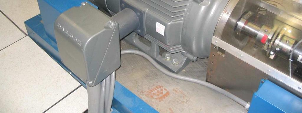
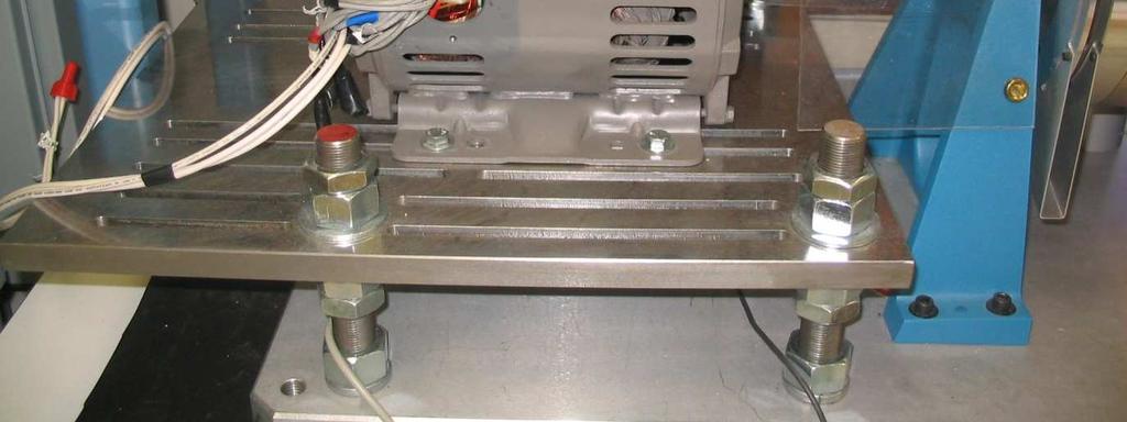
 47 CHAPTER 5 SIMULATION AND TEST SETUP FOR FAULT ANALYSIS 5.1 INTRODUCTION This chapter describes the simulation model and experimental set up used for the fault analysis. For the simulation set up, the
International Journal of Advance Engineering and Research Development
 Scientific Journal of Impact Factor (SJIF): 4.7 International Journal of Advance Engineering and Research Development Volume 4, Issue 5, May-07 e-issn (O): 348-4470 p-issn (P): 348-6406 Mathematical modeling
An Introduction to Electrical Machines. P. Di Barba, University of Pavia, Italy
 An Introduction to Electrical Machines P. Di Barba, University of Pavia, Italy Academic year 0-0 Contents Transformer. An overview of the device. Principle of operation of a single-phase transformer 3.
PROBLEM SOLUTIONS: Chapter 4
 48 PROBLEM SOLUTIONS: Chapter 4 Problem 4.1 ω m = 100 π/30 = 40π rad/sec part (b): 60 Hz; 10π rad/sec part (c): 100 5/6 = 1000 r/min Problem 4. The voltages in the remaining two phases can be expressed
Representation of a Group of Three-phase Induction Motors Using Per Unit Aggregation Model A.Kunakorn and T.Banyatnopparat
 epreentation of a Group of Three-phae Induction Motor Uing Per Unit Aggregation Model A.Kunakorn and T.Banyatnopparat Abtract--Thi paper preent a per unit gregation model for repreenting a group of three-phae
MATLAB SIMULINK Based DQ Modeling and Dynamic Characteristics of Three Phase Self Excited Induction Generator
 628 Progress In Electromagnetics Research Symposium 2006, Cambridge, USA, March 26-29 MATLAB SIMULINK Based DQ Modeling and Dynamic Characteristics of Three Phase Self Excited Induction Generator A. Kishore,
Introduction to Synchronous. Machines. Kevin Gaughan
 Introduction to Synchronous Machines Kevin Gaughan The Synchronous Machine An AC machine (generator or motor) with a stator winding (usually 3 phase) generating a rotating magnetic field and a rotor carrying
EFFECTS OF LOAD AND SPEED VARIATIONS IN A MODIFIED CLOSED LOOP V/F INDUCTION MOTOR DRIVE
 Nigerian Journal of Technology (NIJOTECH) Vol. 31, No. 3, November, 2012, pp. 365 369. Copyright 2012 Faculty of Engineering, University of Nigeria. ISSN 1115-8443 EFFECTS OF LOAD AND SPEED VARIATIONS
Synchronous Machine Modeling
 ECE 53 Session ; Page / Fall 07 Synchronous Machine Moeling Reference θ Quarature Axis B C Direct Axis Q G F D A F G Q A D C B Transient Moel for a Synchronous Machine Generator Convention ECE 53 Session
Lecture (20) DC Machine Examples Start of Synchronous Machines
 DC Machine Examples Start of Synchronous Machines") Lecture (20) DC Machine Examples Start of Synchronous Machines Energy Systems Research Laboratory, FIU All rights reserved. 20-1 Energy Systems Research Laboratory, FIU All rights reserved. 20-2 Ra R f
Lecture (20) DC Machine Examples Start of Synchronous Machines Energy Systems Research Laboratory, FIU All rights reserved. 20-1 Energy Systems Research Laboratory, FIU All rights reserved. 20-2 Ra R f
ECE 422/522 Power System Operations & Planning/ Power Systems Analysis II 2 Synchronous Machine Modeling
 ECE 422/522 Power System Operations & Planning/ Power Systems Analysis II 2 Synchronous achine odeling Spring 214 Instructor: Kai Sun 1 Outline Synchronous achine odeling Per Unit Representation Simplified
From now, we ignore the superbar - with variables in per unit. ψ ψ. l ad ad ad ψ. ψ ψ ψ
 From now, we ignore the superbar - with variables in per unit. ψ 0 L0 i0 ψ L + L L L i d l ad ad ad d ψ F Lad LF MR if = ψ D Lad MR LD id ψ q Ll + Laq L aq i q ψ Q Laq LQ iq 41 Equivalent Circuits for
Lecture 7: Synchronous Motor Drives
 1 / 46 Lecture 7: Synchronous Motor Drives ELEC-E8402 Control of Electric Drives and Power Converters (5 ECTS) Marko Hinkkanen Spring 2017 2 / 46 Learning Outcomes After this lecture and exercises you
The Influence of the Load Condition upon the Radial Distribution of Electromagnetic Vibration and Noise in a Three-Phase Squirrel-Cage Induction Motor
 The Influence of the Load Condition upon the Radial Ditribution of Electromagnetic Vibration and Noie in a Three-Phae Squirrel-Cage Induction Motor Yuta Sato 1, Iao Hirotuka 1, Kazuo Tuboi 1, Maanori Nakamura
Induction Motors. The single-phase induction motor is the most frequently used motor in the world
 Induction Motor The single-phase induction motor is the most frequently used motor in the world Most appliances, such as washing machines and refrigerators, use a single-phase induction machine Highly
AC Induction Motor Stator Resistance Estimation Algorithm
 7th WSEAS International Conference on Electric Power Systems, High Voltages, Electric Machines, Venice, Italy, November 21-23, 27 86 AC Induction Motor Stator Resistance Estimation Algorithm PETR BLAHA
Lecture Set 5 Distributed Windings and Rotating MMF
 Lecture Set 5 Distributed Windings and Rotating MMF S.D. Sudhoff Spring 2017 Distributed Windings and Rotating MMF Objective In this chapter, we will set the stage to study ac machinery including permanent
Dynamic Simulation of a Three-Phase Induction Motor Using Matlab Simulink
 Dynamic Simulation of a ThreePhae Induction Motor Uing Matlab Simulink Adel Aktaibi & Daw Ghanim, graduate tudent member, IEEE, M. A. Rahman, life fellow, IEEE, Faculty of Engineering and Applied Science,
Simulation of 3-Phase 2- Stator Induction Motor Using MATLAB Platform
 International Journal of Alied Engineering Research ISSN 0973-456 Volume 3, Number (08). 9437-944 Simulation of 3-Phase - Stator Induction Motor Using MATLAB Platform Pallavi R.Burande Deartment of Electrical
Comparison of Hardware Tests with SIMULINK Models of UW Microgrid
 Comparion of Hardware Tet with SIMULINK Model of UW Microgrid Introduction Thi report include a detailed dicuion of the microource available on the Univerity- of- Wiconin microgrid. Thi include detail
Revision Guide for Chapter 15
 Revision Guide for Chapter 15 Contents Revision Checklist Revision otes Transformer...4 Electromagnetic induction...4 Lenz's law...5 Generator...6 Electric motor...7 Magnetic field...9 Magnetic flux...
Texas A & M University Department of Mechanical Engineering MEEN 364 Dynamic Systems and Controls Dr. Alexander G. Parlos
 Texas A & M University Department of Mechanical Engineering MEEN 364 Dynamic Systems and Controls Dr. Alexander G. Parlos Lecture 6: Modeling of Electromechanical Systems Principles of Motor Operation
Analysis of the Dynamic Characteristics of an Isolated Self-Excited Induction Generator Driven by a Wind-Turbine
 International Journal of Scientific & Engineering Research Volume 2, Issue 2, February-2012 1 Analysis of the Dynamic Characteristics of an Isolated Self-Excited Induction Generator Driven by a Wind-Turbine
Mathematical Modelling of Permanent Magnet Synchronous Motor with Rotor Frame of Reference
 Mathematical Modelling of Permanent Magnet Synchronous Motor with Rotor Frame of Reference Mukesh C Chauhan 1, Hitesh R Khunt 2 1 P.G Student (Electrical),2 Electrical Department, AITS, rajkot 1 mcchauhan1@aits.edu.in
The Control of a Continuously Operated Pole-Changing Induction Machine
 The Control of a Continuously Operated PoleChanging Induction Machine J.W. Kelly Electrical and Computer Engineering Michigan State University East Lansing, MI 48824 28 February 2002 MD Lab 1/0202 1 Outline
ROEVER COLLEGE OF ENGINEERING & TECHNOLOGY ELAMBALUR, PERAMBALUR DEPARTMENT OF ELECTRICAL AND ELECTRONICS ENGINEERING ELECTRICAL MACHINES I
 ROEVER COLLEGE OF ENGINEERING & TECHNOLOGY ELAMBALUR, PERAMBALUR-621220 DEPARTMENT OF ELECTRICAL AND ELECTRONICS ENGINEERING ELECTRICAL MACHINES I Unit I Introduction 1. What are the three basic types
DESIGN AND MODELLING OF SENSORLESS VECTOR CONTROLLED INDUCTION MOTOR USING MODEL REFERENCE ADAPTIVE SYSTEMS
 DESIGN AND MODELLING OF SENSORLESS VECTOR CONTROLLED INDUCTION MOTOR USING MODEL REFERENCE ADAPTIVE SYSTEMS Janaki Pakalapati 1 Assistant Professor, Dept. of EEE, Avanthi Institute of Engineering and Technology,
The Nottingham eprints service makes this work by researchers of the University of Nottingham available open access under the following conditions.
 Mezani, Smail and Hamiti, Tahar and Belguerras, Lamia and Lubin, Thierry and Gerada, Christopher (215) Computation of wound rotor induction machines based on coupled finite elements and circuit equation
Direct Flux Vector Control Of Induction Motor Drives With Maximum Efficiency Per Torque
 Direct Flux Vector Control Of Induction Motor Drives With Maximum Efficiency Per Torque S. Rajesh Babu 1, S. Sridhar 2 1 PG Scholar, Dept. Of Electrical & Electronics Engineering, JNTUACEA, Anantapuramu,
Modelling and Simulating a Three-Phase Induction Motor
 MURDOCH UNIVERSITY SCHOOL OF ENGINEERING AND INFORMATION TECHNOLOGY Modelling and Simulating a Three-Phase Induction Motor ENG460 Engineering Thesis Benjamin Willoughby 3/3/2014 Executive Summary This
Unified Torque Expressions of AC Machines. Qian Wu
 Unified Torque Expressions of AC Machines Qian Wu Outline 1. Review of torque calculation methods. 2. Interaction between two magnetic fields. 3. Unified torque expression for AC machines. Permanent Magnet
Generalized Theory of Electrical Machines- A Review
 Generalized Theory of Electrical Machines- A Review Dr. Sandip Mehta Department of Electrical and Electronics Engineering, JIET Group of Institutions, Jodhpur Abstract:-This paper provides an overview
TRANSIENT ANALYSIS OF SELF-EXCITED INDUCTION GENERATOR UNDER BALANCED AND UNBALANCED OPERATING CONDITIONS
 TRANSIENT ANALYSIS OF SELF-EXCITED INDUCTION GENERATOR UNDER BALANCED AND UNBALANCED OPERATING CONDITIONS G. HARI BABU Assistant Professor Department of EEE Gitam(Deemed to be University), Visakhapatnam
Synchronous Machines
 Synchronous machine 1. Construction Generator Exciter View of a twopole round rotor generator and exciter. A Stator with laminated iron core C Slots with phase winding B A B Rotor with dc winding B N S
Simulation and Analysis of Linear Permanent Magnet Vernier Motors for Direct Drive Systems
 Available online at www.ijpe-online.com vol. 3, no. 8, December 07, pp. 304-3 DOI: 0.3940/ijpe.7.08.p.3043 Simulation and Analyi of Linear Permanent Magnet Vernier Motor for Direct Drive Sytem Mingjie
Dynamic Modeling of Surface Mounted Permanent Synchronous Motor for Servo motor application
 797 Dynamic Modeling of Surface Mounted Permanent Synchronous Motor for Servo motor application Ritu Tak 1, Sudhir Y Kumar 2, B.S.Rajpurohit 3 1,2 Electrical Engineering, Mody University of Science & Technology,
Dynamic Modeling Of A Dual Winding Induction Motor Using Rotor Reference Frame
 American Journal of Engineering Research (AJER) e-issn: 2320-0847 p-issn : 2320-0936 Volume-7, Issue-11, pp-323-329 www.ajer.org Research Paper Open Access Dynamic Modeling Of A Dual Winding Induction
Vector Controlled Power Generation in a Point Absorber Based Wave Energy Conversion System
 Vector Controlled Power Generation in a Point Absorber Based Wave Energy Conversion System Jisha Thomas Chandy 1 and Mr. Vishnu J 2 1,2 Electrical & Electronics Dept of Engineering, Sree Buddha College
Characteristic Study for Integration of Fixed and Variable Speed Wind Turbines into Transmission Grid
 Characteristic Study for Integration of Fixed and Variable Speed Wind Turbines into Transmission Grid Shuhui Li 1, Tim Haskew 1, R. Challoo 1 Department of Electrical and Computer Engineering The University
Lecture 8: Sensorless Synchronous Motor Drives
 1 / 22 Lecture 8: Sensorless Synchronous Motor Drives ELEC-E8402 Control of Electric Drives and Power Converters (5 ECTS) Marko Hinkkanen Spring 2017 2 / 22 Learning Outcomes After this lecture and exercises
SIMULATION MODEL FOR PREDICTION OF TRANSIENT PERFORMANCE CHARACTERISTICS OF SINGLE PHASE SHADED POLE MOTOR
 Journal of ELECTRICAL ENGINEERING, VOL 67 (216), NO4, 253 26 SIMULATION MODEL FOR PREDICTION OF TRANSIENT PERFORMANCE CHARACTERISTICS OF SINGLE PHASE SHADED POLE MOTOR Vasilija Sarac Tatjana Atanasova-Pacemska
DEVELOPMENT OF DIRECT TORQUE CONTROL MODELWITH USING SVI FOR THREE PHASE INDUCTION MOTOR
 DEVELOPMENT OF DIRECT TORQUE CONTROL MODELWITH USING SVI FOR THREE PHASE INDUCTION MOTOR MUKESH KUMAR ARYA * Electrical Engg. Department, Madhav Institute of Technology & Science, Gwalior, Gwalior, 474005,
Sensorless PMSM Field Oriented Control Solution Based on TI Cortex-M3
 Senorle PMSM Field Oriented Control Solution Baed on TI Cortex-M3 AEDS Team Technical Service Arrow Steven Wang Agenda Permanent Magnet Synchronou Motor Field Oriented Control Realization Senorle Control
Mutual Inductance. The field lines flow from a + charge to a - change
 Capacitors Mutual Inductance Since electrical charges do exist, electric field lines have a starting point and an ending point. For example, if you have a + and a - change, the field lines would look something
Electric Machines I Three Phase Induction Motor. Dr. Firas Obeidat
 Electric Machines I Three Phase Induction Motor Dr. Firas Obeidat 1 Table of contents 1 General Principles 2 Construction 3 Production of Rotating Field 4 Why Does the Rotor Rotate 5 The Slip and Rotor
Dynamics of the synchronous machine
 ELEC0047 - Power system dynamics, control and stability Dynamics of the synchronous machine Thierry Van Cutsem t.vancutsem@ulg.ac.be www.montefiore.ulg.ac.be/~vct October 2018 1 / 38 Time constants and
Per Unit Analysis. Single-Phase systems
 Per Unit Analyi The per unit method of power ytem analyi eliminate the need for converion of voltae, current and impedance acro every tranformer in the circuit. n addition, the need to tranform from 3-
UNIT I INTRODUCTION Part A- Two marks questions
 ROEVER COLLEGE OF ENGINEERING & TECHNOLOGY ELAMBALUR, PERAMBALUR-621220 DEPARTMENT OF ELECTRICAL AND ELECTRONICS ENGINEERING DESIGN OF ELECTRICAL MACHINES UNIT I INTRODUCTION 1. Define specific magnetic
Three phase induction motor using direct torque control by Matlab Simulink
 Three phase induction motor using direct torque control by Matlab Simulink Arun Kumar Yadav 1, Dr. Vinod Kumar Singh 2 1 Reaserch Scholor SVU Gajraula Amroha, U.P. 2 Assistant professor ABSTRACT Induction
Modelling and simulation of induction motors with inter-turn faults for diagnostics
 Electric Power Sytem Reearch 75 5) 57 66 Modelling and imulation of induction motor with inter-turn fault for diagnotic M. Arkan a, D. Kotic-Perovic b, P.J. Unworth c, a Inonu Univerity, Engineering Faculty,
Proceedings of the 6th WSEAS/IASME Int. Conf. on Electric Power Systems, High Voltages, Electric Machines, Tenerife, Spain, December 16-18,
 Proceedings of the 6th WSEAS/IASME Int. Conf. on Electric Power Systems, High Voltages, Electric Machines, Tenerife, Spain, December 16-18, 2006 196 A Method for the Modeling and Analysis of Permanent
AN EFFICIENT APPROACH FOR ANALYSIS OF ISOLATED SELF EXCITED INDUCTION GENERATOR
 AN EFFICIENT APPROACH FOR ANALYSIS OF ISOLATED SELF EXCITED INDUCTION GENERATOR Deepika 1, Pankaj Mehara Assistant Professor, Dept. of EE, DCRUST, Murthal, India 1 PG Student, Dept. of EE, DCRUST, Murthal,
MATHEMATICAL MODELING OF INDUCTION MOTORS
 37 CHAPTER 3 MATHEMATICAL MODELING OF INDUCTION MOTORS To tart with, a well-known technique called the SVPWM technique i dicued a thi form the bai of the mathematical modeling of IM. Furthermore, the d
Computation of Wound Rotor Induction Machines Based on Coupled Finite Elements and Circuit Equation under a First Space Harmonic Approximation
 Computation of Wound Rotor Induction Machines Based on Coupled Finite Elements and Circuit Equation under a First Space Harmonic Approximation Smail Mezani, Tahar Hamiti, Lamia Belguerras, Thierry Lubin,
ON THE PARAMETERS COMPUTATION OF A SINGLE SIDED TRANSVERSE FLUX MOTOR
 ON THE PARAMETERS COMPUTATION OF A SINGLE SIDED TRANSVERSE FLUX MOTOR Henneberger, G. 1 Viorel, I. A. Blissenbach, R. 1 Popan, A.D. 1 Department of Electrical Machines, RWTH Aachen, Schinkelstrasse 4,
NAVAL POSTGRADUATE SCHOOL THESIS
 NAVAL POSTGRADUATE SCHOOL MONTEREY, CALIFORNIA THESIS DOUBLY FED INDUCTION MACHINE CONTROL FOR WIND ENERGY CONVERSION by Jason G. Massey June 2009 Thesis Advisor: Second Reader: Alexander Julian Roberto
Transient Analysis of Three Phase Squirrel Cage Induction Machine using Matlab
 Transient Analysis of Three Phase Squirrel Cage Induction Machine using Matlab Mukesh Kumar Arya*, Dr.Sulochana Wadhwani** *( Department of Electrical Engineering, Madhav Institute of Technology & Science,
PERFORMANCE ANALYSIS OF DIRECT TORQUE CONTROL OF 3-PHASE INDUCTION MOTOR
 PERFORMANCE ANALYSIS OF DIRECT TORQUE CONTROL OF 3-PHASE INDUCTION MOTOR 1 A.PANDIAN, 2 Dr.R.DHANASEKARAN 1 Associate Professor., Department of Electrical and Electronics Engineering, Angel College of
2016 Kappa Electronics Motor Control Training Series Kappa Electronics LLC. -V th. Dave Wilson Co-Owner Kappa Electronics.
 2016 Kappa Electronics Motor Control Training Series 2016 Kappa Electronics C V th CoOwner Kappa Electronics www.kappaiq.com Benefits of Field Oriented Control NewtonMeters Maximum Torque Per Amp (MTPA)
Finite Element Analysis of Hybrid Excitation Axial Flux Machine for Electric Cars
 223 Finite Element Analysis of Hybrid Excitation Axial Flux Machine for Electric Cars Pelizari, A. ademir.pelizari@usp.br- University of Sao Paulo Chabu, I.E. ichabu@pea.usp.br - University of Sao Paulo
Step Motor Modeling. Step Motor Modeling K. Craig 1
 Step Motor Modeling Step Motor Modeling K. Craig 1 Stepper Motor Models Under steady operation at low speeds, we usually do not need to differentiate between VR motors and PM motors (a hybrid motor is
Experimental and Finite Element Analysis of an Electronic Pole-Change Drive
 Experimental and Finite Element Analysis of an Electronic Pole-Change Drive Mohamed Osama Thomas A. Lipo General Electric Company University of Wisconsin - Madison Corporate Research and Development Center
CHAPTER 2 MODELLING OF INTERIOR PERMANENT MAGNET SYNCHRONOUS MOTOR
 21 CHAPTER 2 MODELLING OF INTERIOR PERMANENT MAGNET SYNCHRONOUS MOTOR 2.1 INTRODUCTION The need for adjustable speed drives in industrial applications has been increasing progressively. The variable speed
Estimation of Temperature Rise in Stator Winding and Rotor Magnet of PMSM Based on EKF
 2010 3rd International Conference on Computer and Electrical Engineering (ICCEE 2010) IPCSIT vol. 53 (2012) (2012) IACSIT Pre, Singapore DOI: 10.7763/IPCSIT.2012.V53.No.2.37 Etimation of Temperature Rie
Doubly salient reluctance machine or, as it is also called, switched reluctance machine. [Pyrhönen et al 2008]
![Doubly salient reluctance machine or, as it is also called, switched reluctance machine. [Pyrhönen et al 2008]](/thumbs/86/93665357.jpg "Doubly salient reluctance machine or, as it is also called, switched reluctance machine. [Pyrhönen et al 2008]") Doubly salient reluctance machine or, as it is also called, switched reluctance machine [Pyrhönen et al 2008] Pros and contras of a switched reluctance machine Advantages Simple robust rotor with a small
Doubly salient reluctance machine or, as it is also called, switched reluctance machine [Pyrhönen et al 2008] Pros and contras of a switched reluctance machine Advantages Simple robust rotor with a small