Finite Element Analysis of Hybrid Excitation Axial Flux Machine for Electric Cars
|
|
|
- Gervais Jacobs
- 5 years ago
- Views:
Transcription
1 223 Finite Element Analysis of Hybrid Excitation Axial Flux Machine for Electric Cars Pelizari, A. University of Sao Paulo Chabu, I.E. - University of Sao Paulo Abstract this paper presents a FEM analysis of a hybrid excitation brushless axial flux machine (HEBAFM) for traction electric vehicle purposes in order to compare with the results from an analytical method used to determine the flux densities in each part of the machine. The magnetic quantities of the proposed topology were investigated in order to obtain a satisfactory level of flux densities avoiding a possible saturation of the material. Keeping the magnetic induction under the saturation point, it will be feasible to increase the speed beyond the rated speed. The results from using the analytical method as well as via FEM simulation analysis presented a good approximation and are shown at the end of this paper. Index Terms electric traction motor; electric vehicle application; hybrid excitation axial flux machine; simulation of electric motors. I. INTRODUCTION DC motors haves been used for almost two centuries. This is easily explained not only because it can operate at the flux weakening region but also for its excellent torque response. In order to solve the problem of the exhaustive electromechanical maintenance in this type of machine, during the 1960s, permanent magnet brushless dc machines were developed. The drawback of these machines is the difficulty in controlling the speed, especially when flux weakening region operation is required. Hence the main purpose of this paper is a comparative study of a Hybrid Excitation Brushless Axial Flux Machine [1] topology proposed in Figure 1, using the finite element analysis via 3D simulation software and the analytical method to make its operation at the constant power region possible keeping the flux density level in the critical parts of the machine under the saturation point. II. THE AXIAL FLUX MOTOR EQUATION TORQUE The first step during the development of the topology was to predict the developed torque upon its main dimensions and magnetic variables of the machine. The developed torque equation of the double side axial flux motor can be calculated as follows [2]: 3 3 d 1AVG d d OUT T 2.. B. A. [ K - K ]. (R ) (1)
![Developed Torque [Nm] Journal of Microwaves, Optoelectronics and Electromagnetic Applications, Vol. 13, No. 2, December 2014 224 Fig.1. Side and frontal views of the axial flux topology proposed.](/docs-images/82/86811567/images/2-0.jpg "In (1), R OUT is the outer radius of the disc in meters, A is the rms linear current density, i.e., Am/2-1/2 in Ampère.")

2 Developed Torque [Nm] Journal of Microwaves, Optoelectronics and Electromagnetic Applications, Vol. 13, No. 2, December Fig.1. Side and frontal views of the axial flux topology proposed. In (1), R OUT is the outer radius of the disc in meters, A is the rms linear current density, i.e., Am/2-1/2 in Ampère.turns/meter, B 1AVG the fundamental air gap average flux density in Tesla, K d is the diameter factor of the disc. The constant Am is the peak of the linear current density and it can be calculated as: Am m N 1. I A / (. (R IN + (ROUT R IN / 2)) (2) In (2), m 1 represents the number of phases of the stator, N 1 the number of turns of the armature winding and I A the phase current of the stator winding. The air gap average flux density in (1) can be obtained in terms of the air gap maximum flux density B g, as in (3) B 1AVG (2 / ). 2. B g. sin. / 2 The term in (3) is the relationship between coil pitch and pole pitch. Therefore, once the average flux density has already been defined, the developed torque behavior can be viewed as in Figure 2 as a function of both linear current density and average flux density. (3) Outer Radius [m] x 10 4 Linear Current Density [A.esp /m] Fig.2. Developed Torque as Function of Linear Current Density and Air Gap Average Flux Density.
3 225 III. ARMATURE DESIGN In this step, the sizing of armature was based on its main dimensions obtained through the equations in section II as well as on its rated data. The general data and the rated characteristics of the hybrid excitation axial flux machine topology proposed are shown in Table I. TABLE I PROPOSED TOPOLOGY DATA. General Data 1 Rated Power 10 kw 2 Three-Phase Supply Voltage 440 V 2 Synchronous Speed - (N S ) e (n S ) 600 rpm - 10 rps 3 Maximum Linear Current Density (A M ) Maximum Airgap Flux Density [9] 0,65 T 5 Max. Airgap Flux Weakening Density 0,325 T 6 Voltage Factor ( ) 0,9 7 Coil pitch / Pole pitch Ratio 0,637 In this type of machine, due the greater disc diameter, the ratio of speed of the topology proposed was 600/1200 revolutions per second to avoid vibration of the machine, i.e., ratio of speed of 1:2 and therefore the air gap flux density ratio adopted was 2:1. Hence, the number of poles can be determined as: p (2. f. 60) / NS In (4), f is the rated frequency in (Hz), Ns the synchronous speed in rpm. After calculating the number of poles, the next step was to obtain the average flux density B 1AVG as a function of peak air gap flux density calculation. Hence, the fundamental flux density per pole can be calculated as in (5): (4) /p B1AVG 1/ / p B 1MAX. sin (p ) d Based on average flux density per pole, the magnetic flux per pole is determined as 0 (5) Thus, replacing (6) in (5), results in Rout Rout B 1. dsp B π. r. dr / p POLE AVG POLE AVG Rin Rin 2 2 α. B POLE 1. / 8.pp. (D ) - (D ) MAX OUT IN (6) (7) Since K d is a diameter factor it can be obtained as Kd = D OUT / D IN (8) Substituting the K d factor in (8), after some mathematical treatment results
4 Outer Diameter of the Disc [m] Flux per Pole [Wb] Journal of Microwaves, Optoelectronics and Electromagnetic Applications, Vol. 13, No. 2, December α. B. ( / 8. pp). D (1 K ) POLE MAX OUT d (9) Pair of Poles Outer Diameter [m] Fig.3. Relationship among POLE, D OUT and pair of poles. The Figure 3 illustrates the dependence of the flux per pole as a function of D OUT and pair of poles. K D is the dimension factor as a function of K d, which can be calculated as 2 D d d K (1 K ). (1-K ) (10) Hence, the outer diameter of the axial flux motor disc can be determined as follows [4] 2 D OUT. P N /(. K D. K ω1. n s. B 1 MAX. A M. η.cos ) 1/3 (11) Referring to (11) the outer diameter variation can be seen as in Figure 4 since the K D, K 1, n s factors are constant x Linear Current Density [A.turns/m] Maximum Flux Density [T] Fig.4. Behavior of D out f (B 1MAX (T), A M (A.t/m). And the inner diameter is consequently DIN D OUT / 3 (12) The armature data and its main characteristics are presented in Table II.
5 227 TABLE II ARMATURE DATA. Item Armature 1 Armature Core FeSi 2 Isotropic Radial Orientation NGOES E Type Core-Slot 4 Outer Diameter (D OUT ) 0,313 m 5 Inner Diameter (D IN ) 0,181 m 6 Number of Slots 36 7 Diameter Factor (K d ) 0, Dimension Fator (K D ) 0,131 9 Stacking Factor (K STACK ) 0,9 10 Leakage Factor (K LEAK ) 0,1 As the topology is a double side stator machine, the number of turns per phase per stator can be calculated as N 1. V 1 / (. 2. f. K ω1. POLE) (13) Since both sides of the armature windings were in series wye connection (Y), the electric current of the armature can be determined by IAP N/ (m (V L / 3). COS φ. ) (14) Thus, Table III summarizes the main data of the armature winding. TABLE III ARMATURE WINDING DATA. Item Armature Winding Data 1 Type of Winding Concentrated 2 Number of Layers 1 3 Number of Phases (m 1 ) 3 4 Number of Poles (p) 24 5 Number of Coils (N COILS ) 36 6 Number of Turns per Phase (N 1 ) Number of Turns / Coil 20 8 Number of parallel paths (a W ) 4 9 Winding Factor ( K 1 ) 1 10 Rated Frequency (f) 120 Hz 11 Rated Current (I A ) 15 A IV. Using (1), the three-phase calculated developed torque in both conditions can be viewed in Table

6 228 TABLE IV ANALYTICAL TORQUE RESULT. Item Calculated Torque 1 Three-Phase Developed Torque (Td)-Rated 145,76 Nm 2 Three-Phase Developed Torque (Td)-Weake 72,88 Nm IV. HYBRID EXCITATION DESIGN To avoid disc vibration, a ratio of speed of 600/1200 rpm was selected, thus, a maximum air gap flux density of 0.65 T produced by hybrid excitation for 600 rpm was adopted herein. Consequently, at the flux weakening region, half the maximum air gap flux density, for a maximum speed of 1200 rpm, only PM excitation was considered. Basically, the hybrid excitation [5,6] proposed is composed of two systems as in Figures 5a and 5b: one system consists of 2 pairs of coils with 875 turns allocated at the outer and the inner part of the armature and fixed at the cover, which produces up to T controlled by a d.c. source with maximum voltage of 100 V. The latter is a permanent magnet system as in Figure 5b composed of 24 NdFeB-35 permanent magnets fixed to the rotor which produces T. The main concern is to prevent saturation from occurring in the ferromagnetic cores, for instance, teeth, yokes or even in the cover, since that not only one, but two armature windings provide magnetic flux through the rotor. DC EXCITATION COILS PERMANENT MAGNET EXCITATION ROTOR a) b) Fig.5. Excitation system. a) Detail of the dc excitation coils. b) PM excitation. A magnetic equivalent circuit was designed in order to calculate the flux densities in the most relevant parts of the topology. Figures 6 and 7 illustrate the pathway flux and Figures 8 and 9 the equivalent circuit with both excitation systems.
7 229 Fig. 6. Pathway of magnetic flux produced by the electric excitation. Fig. 7. Pathway of magnetic flux produced by PM excitation R COVER_TOP F EXC_ELET RARM_YOKE R COVER_BOTT R ARM_TEETH R COVER_BOTT R g R POLE R g R g R POLE R g R OUTER_YOKE R INNER_YOKE Fig. 8. Magnetic equivalent circuit due to the electric excitation.
8 230 R ARM_YOKE R ARM_TEETH R g R g R POLE F PM R POLE Fig.9. Magnetic equivalent circuit due to the PM excitation. Fig.10. Detail of the rotor pole. Referring to Figure 10, average flux density B 1AVG becomes: B ( ) B 1AVG POLE / POLE _ PITCH g (15) From (15), the flux per pole can be determined since S P is the area of the pole B S POLE 1AVG P (16) Since the flux per pole is produced by two stators, the flux density at the pole as a function of a minimum area as in Figure 11, becomes: B MIN_AREA 2 POLE K LEAK / SP _ MIN (17)
 Hence the flux density at the inner yoke of the rotor becomes B ( ) / S.")
 And the flux density at the teeth of the armature can be calculated as B ARM _ TEETH = (Φ POLE) / SARM _ TEETH. KF. KSTACK.")
9 231 Fig.11. View of the magnetic flux pathway in the rotor and the minimum area of the pole. The flux per pole at the inner yoke of the rotor can be determined by INNER_YOKE POLE LEAK. K. 2p / 2 (18) Hence the flux density at the inner yoke of the rotor becomes B ( ) / S. K INNER _ YOKE INNER _ YOKE INNER _ YOKE STACK (19) The flux density at the outer yoke of the rotor is B OUTER_YOKE = (Φ OUTER_YOKE ) / S OUTER_YOKE. KSTACK (20) And the flux density at the teeth of the armature can be calculated as B ARM _ TEETH = (Φ POLE) / SARM _ TEETH. KF. KSTACK. N SLOTS / p (21) In (21), the term S ARM_TEETH represents the area of the armature teeth, K STACK is the stacking factor. Lastly, the flux density at the yoke of the armature was calculated as in (22), i.e. B ( 2) / S. K ARM _ YOKE POLE / ARM _ YOKE STACK (22) Using the magnetization curve given in figure 12 and the formulas from (15) up to (22), the flux density in each part of the machine can be calculated analytically. The calculated values are shown in Tables V, VI and VIII with double excitation, electric excitation and permanent magnet excitation only, respectively.
 Avg _length MMF (A.t) (m) Airgap 0.65 0.0025 1034.51 Stator (NGOES E230) Arm_teeth 0.98 0.01 1.37 Arm_yoke 0.56 0.011 1.01 Rotor (NGOES E230) Inner_yoke 0.405 0.0027 0.")
10 232 Silicon Iron SAE Steel Magnetic Flux Density ( T ) Magnetic Field Intensity (A/cm) Fig.12. B-H Curve of silicon iron E230 and SAE 1020 steel. TABLE V MAGNETIC CIRCUIT WITH DOUBLE EXCITATION. Part Quantities B (T) Avg _length MMF (A.t) (m) Airgap Stator (NGOES E230) Arm_teeth Arm_yoke Rotor (NGOES E230) Inner_yoke Outer_yoke Pole Cover (SAE 1020 steel) Cover_bott Cover_top Total TABLE VI MAGNETIC CIRCUIT WITH ELECTRIC EXCITATION. Part Quantities B (T) Avg _length (m) MMF (A.t) Airgap Stator (NGOES E230) Arm_teeth Arm_yoke Rotor (NGOES E230) Inner_yoke Outer_yoke Pole Cover (SAE 1020 steel) Cover_bott Cover_top Total
11 233 TABLE VII MAGNETIC CIRCUIT WITH PM EXCITATION ONLY. Part Quantities B (T) Avg _length MMF (A.t) (m) Airgap Stator (NGOES E230) Arm_teeth Arm_yoke Rotor (NGOES E230) Inner_yoke Outer_yoke Pole Total 260 V. FEM ANALYSIS This section presented the results of the finite element analysis in magnetostatic and transient analysis simulation via 3D software compare them with those of the analytical solution. The problem formulation in a magnetostatic study is 1 2 A J (23) In (23), J is the current density, A is the magnetic vector potential and is the magnetic permeability of the medium. The current sources were imposed with their rated values which are 15 A in the armature winding and in electric excitation coils 1.6 A respectively according to the magnetomotive force calculated from Table VI. In this type of solution, the solver assumes that the electric current is uniformly distributed over the cross section of the coil and the direction of the current is determined by the arrows as in Figures 13a and 13b. a) b) Fig.13. Paths of current. a) Electric excitation b) Armature winding.


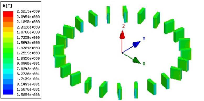
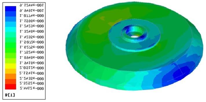
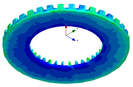
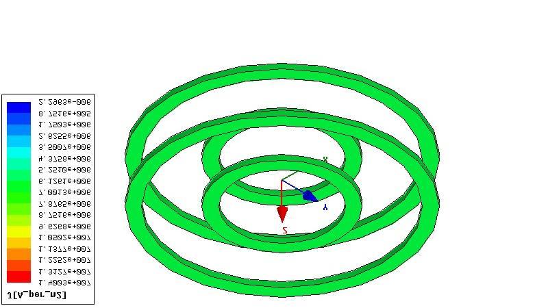
12 234 Figures 14 and 15 illustrate the color map simulations of the topology in both conditions. Fig.14. Color map results of the flux densities and current density under rated conditions.

 + 1.94 (T) -1.89 (T) 6 Cover_bott 1.68 (T) + 1.75 (T) -1.62 (T) 7 Cover_top 1.76 (T) + 1.75 (T) -1.62 (T) TABLE IX FLUX DENSITY RESULTS FLUX WEAKENING CONDITION.")
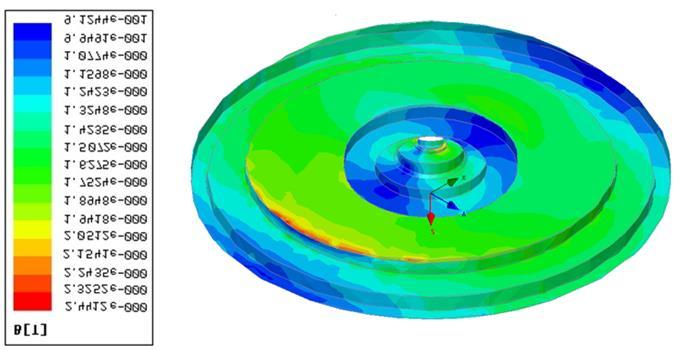
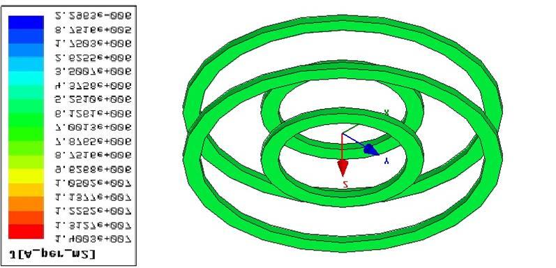
13 235 Fig.15. Color map of the flux densities density under flux weakening conditions. In summary, the flux densities calculated in the motor as well as the FEM results are presented in Table VIII and Table IX, respectively TABLE VIII FLUX DENSITY RESULTS RATED CONDITION. Item Local Analytical FEM 1 Arm_teeth 0.98 (T) (T) (T) 2 Arm_yoke 0.56 (T) (T) (T) 3 Inner_yoke (T) (T) (T) 4 Outer_yoke 0.27 (T) (T) (T) 5 Pole 1.94 (T) (T) (T) 6 Cover_bott 1.68 (T) (T) (T) 7 Cover_top 1.76 (T) (T) (T) TABLE IX FLUX DENSITY RESULTS FLUX WEAKENING CONDITION. Item Local Analytical FEM 1 Arm_teeth 0,49 (T) (T) (T) 2 Arm_yoke 0,28 (T) (T) (T) 3 Pole 0,97 (T) (T) (T) A transient simulation analysis with constant speed imposed was carried out in both working
 The constant, and are respectively the magnetic reluctivity, electric conductivity and constant")
14 236 conditions. The formulation of constant speed magnetic transient analysis is A x x A J - - V x H C x x A t (24) The constant, and are respectively the magnetic reluctivity, electric conductivity and constant speed in steady state regime. In the same equation, V is the scalar electric potential of the source, Hc is the coercive field intensity of the permanent magnets. Table IX presents the quantities used in the simulation TABLE X QUANTITIES OF THE SIMULATION. General Data 1 Scalar electric potential (V) 440 V 2 Synchronous Speed - () 600 rpm rpm 3 Coercive field intensity (Hc) 1006,513 k A/m 4 Frequency of the source 120 Hz 5 Synch armature winding inductance (Ls d ) 11,6 mh 6 Armature winding resistance (R1) 0, Electric excitation resistance (Rexc_ext) 24,33 8 Electric excitation resistance (Rexc_int) 48,64 For convenience, due the memory size of the computer, only ¼ of the geometry was simulated as in Figure 16. Fig.16. Detail of the simulated geometry. The transient regime simulations with constant speed were carried out for two flux conditions, both of them an external electric circuit coupled. Figure 17a shows the electric circuit with a three-phase source connected to the armature winding and a dc rectifier converter feeding the electric excitation
15 237 circuit. However, Figure 17 b presents only three-phase armature windings since there is no dc current at 1200 rpm. a) b) Fig.17. External electric circuit coupled to the geometry simulated. a) Rated conditions. b) Flux weakening conditions. At the end of the simulation, the harmonics of field at steady state were extracted up to the 40 th harmonic, as illustrated in Figure 18 with double excitation at 600 rpm.
![Developed Torque [Nm] Journal of Microwaves, Optoelectronics and Electromagnetic Applications, Vol. 13, No.](/docs-images/82/86811567/images/16-1.jpg "2, December 2014 238 Curve Info freq(induction) Primeira : Transient 120 720 240 360 480 600 840 1440 960 1080 1200 1320 1560 2160 1680 1800 1920 2040 2280 2880 2400 2520 2640 2760 3000 3120 3360")
16 Developed Torque [Nm] Journal of Microwaves, Optoelectronics and Electromagnetic Applications, Vol. 13, No. 2, December Curve Info freq(induction) Primeira : Transient Fig.18. Flux density harmonics. The developed torque calculated from the analytical method over the regions is presented in Figure 19 and the torque obtained through the simulation at rated speed and flux weakening region are presented in Figures 20a and 20b. Table XI summarizes the torque results obtained from the analytical method and simulation Constant Torque Region Constant Power Region DOUBLE FLUX HYBRID EXCITATION (FLUX WEAKENING) PM EXCITATION ONLY [N.m] Speed [rpm] Fig. 19 Analytical torque behavior. a) b) Fig. 20 Simulated torque. a) Rated conditions. b) Flux weakening region.
17 239 TABLE XI DEVELOPED TORQUE RESULTS. Developed Torque Rated Condition Analytical FEM % Flux Weakening Condition Analytical FEM % VI. CONCLUSION The armature core and the rotor disc were designed based on the analytical method varying the dimensions such as area of the pole, area of the yokes and area of the teeth, thus preventing a critical situation which is magnetic saturation, since the saturation point of the ferromagnetic core used in this project was 2,1 Tesla. Through the analytical method and FEM simulations, the results from Table VII and Table VIII show that there was no saturation in any part of the machine, despite the high level of flux density at the minimum area of the pole. In spite of the greater losses at 120 Hz, the efficiency achieved is satisfactory making the topology proposed possible. The torque results obtained analytically and simulated presented good approximation. REFERENCES [1] Caricchi, F.; Crescimbini, F., Axial-flux permanent-magnet machine with water-cooled ironless stator, proc. IEEE Power Tech Conf., pp , [2] Gieras, J.F., R. Wang, and M. J. Kamper, Axial flux permanent magnet brushless machines, [3] Wang, S.; Xia, Y.; Wang, X., State of the art of hybrid excitation permanent magnet synchronous machines, Electrical Machines and Systems (ICEMS), International Conference on, pp , [4] Xia, Y. ; Wang, S. ; Ma, M. ; Hao L.; Qiu A. ; Huang, S.; Basic principles of hybrid excitation PM synchronous generator utilizing harmonic for excitation Electrical Machines and Systems (ICEMS), International Conference on, pp , [5] Kefsi, L.; Touzani, Y.; Gabsi, M., Hybrid Excitation Synchronous Motor control with a new flux weakening strategy, VPPC, IEEE, p.p. 1 5, [6] Kamper, M.; Wang, R., Analysis and performance evaluation of axial flux air-cored stator permanent magnet machine with concentrated coils, IEEE electric machines & drives conference, 2007.
Analytical Calculation of Air Gap Magnetic Field Distribution in Vernier Motor
 IEEE PEDS 017, Honolulu, USA 1-15 June 015 Analytical Calculation of Air Gap Magnetic Field Distribution in Vernier Motor Hyoseok Shi, Noboru Niguchi, and Katsuhiro Hirata Department of Adaptive Machine
Analytical Model for Sizing the Magnets of Permanent Magnet Synchronous Machines
 Journal of Electrical Engineering 3 (2015) 134-141 doi: 10.17265/2328-2223/2015.03.004 D DAVID PUBLISHING Analytical Model for Sizing Magnets of Permanent Magnet Synchronous Machines George Todorov and
AXIAL FLUX INTERIOR PERMANENT MAGNET SYNCHRONOUS MOTOR WITH SINUSOIDALLY SHAPED MAGNETS
 AXIAL FLUX INTERIOR PERMANENT MAGNET SYNCHRONOUS MOTOR WITH SINUSOIDALLY SHAPED MAGNETS A. Parviainen, J. Pyrhönen, M. Niemelä Lappeenranta University of Technology, Department of Electrical Engineering
DESIGN AND ANALYSIS OF AXIAL-FLUX CORELESS PERMANENT MAGNET DISK GENERATOR
 DESIGN AND ANALYSIS OF AXIAL-FLUX CORELESS PERMANENT MAGNET DISK GENERATOR Łukasz DR ZIKOWSKI Włodzimierz KOCZARA Institute of Control and Industrial Electronics Warsaw University of Technology, Warsaw,
Doubly salient reluctance machine or, as it is also called, switched reluctance machine. [Pyrhönen et al 2008]
![Doubly salient reluctance machine or, as it is also called, switched reluctance machine. [Pyrhönen et al 2008]](/thumbs/86/93665357.jpg "Doubly salient reluctance machine or, as it is also called, switched reluctance machine. [Pyrhönen et al 2008]") Doubly salient reluctance machine or, as it is also called, switched reluctance machine [Pyrhönen et al 2008] Pros and contras of a switched reluctance machine Advantages Simple robust rotor with a small
Doubly salient reluctance machine or, as it is also called, switched reluctance machine [Pyrhönen et al 2008] Pros and contras of a switched reluctance machine Advantages Simple robust rotor with a small
ROEVER COLLEGE OF ENGINEERING & TECHNOLOGY ELAMBALUR, PERAMBALUR DEPARTMENT OF ELECTRICAL AND ELECTRONICS ENGINEERING ELECTRICAL MACHINES I
 ROEVER COLLEGE OF ENGINEERING & TECHNOLOGY ELAMBALUR, PERAMBALUR-621220 DEPARTMENT OF ELECTRICAL AND ELECTRONICS ENGINEERING ELECTRICAL MACHINES I Unit I Introduction 1. What are the three basic types
Static Analysis of 18-Slot/16-Pole Permanent Magnet Synchronous Motor Using FEA
 International Journal of Engineering and Technology Volume 5 No. 3,March, 2015 Static Analysis of 18-Slot/16-Pole Permanent Magnet Synchronous Motor Using FEA M. Rezal 1, Dahaman Ishak 2, M. Sabri 1, Al-Hapis
Power density improvement of three phase flux reversal machine with distributed winding
 Published in IET Electric Power Applications Received on 4th January 2009 Revised on 2nd April 2009 ISSN 1751-8660 Power density improvement of three phase flux reversal machine with distributed winding
Loss Minimization Design Using Magnetic Equivalent Circuit for a Permanent Magnet Synchronous Motor
 Loss Minimization Design Using Magnetic Equivalent Circuit for a Permanent Magnet Synchronous Motor Daisuke Sato Department of Electrical Engineering Nagaoka University of Technology Nagaoka, Niigata,
Influence of different rotor magnetic circuit structure on the performance. permanent magnet synchronous motor
 ARCHIVES OF ELECTRICAL ENGINEERING VOL. 66(3), pp. 583-594 (2017) DOI 10.1515/aee-2017-0044 Influence of different rotor magnetic circuit structure on the performance of permanent magnet synchronous motor
Massachusetts Institute of Technology Department of Electrical Engineering and Computer Science Electric Machines
 Massachusetts Institute of Technology Department of Electrical Engineering and Computer Science 6.685 Electric Machines Problem Set 10 Issued November 11, 2013 Due November 20, 2013 Problem 1: Permanent
ON THE PARAMETERS COMPUTATION OF A SINGLE SIDED TRANSVERSE FLUX MOTOR
 ON THE PARAMETERS COMPUTATION OF A SINGLE SIDED TRANSVERSE FLUX MOTOR Henneberger, G. 1 Viorel, I. A. Blissenbach, R. 1 Popan, A.D. 1 Department of Electrical Machines, RWTH Aachen, Schinkelstrasse 4,
A new hybrid method for the fast computation of airgap flux and magnetic forces in IPMSM
 2017 Twelfth International Conference on Ecological Vehicles and Renewable Energies (EVER) A new hybrid method for the fast computation of airgap flux and magnetic forces in IPMSM Emile Devillers, Michel
Analytical Method for Magnetic Field Calculation in a Low-Speed Permanent-Magnet Harmonic Machine
 Vol. 5 No.5/ May. 2011 Analytical Method for Magnetic Field Calculation in a Low-Speed Permanent-Magnet Harmonic Machine ABSTRACT Magnetic-gearing effect has become increasingly attractive when designing
Optimal Design of PM Axial Field Motor Based on PM Radial Field Motor Data
 Optimal Design of PM Axial Field Motor Based on PM Radial Field Motor Data GOGA CVETKOVSKI LIDIJA PETKOVSKA Faculty of Electrical Engineering Ss. Cyril and Methodius University Karpos II b.b. P.O. Box
TRACING OF MAXIMUM POWER DENSITY POINT FOR AXIAL FLUX TORUS TYPE MACHINES USING GENERAL PURPOSE SIZING EQUATIONS
 TRACING OF MAXIMUM POWER DENSITY POINT FOR AXIAL FLUX TORUS TYPE MACHINES USING GENERAL PURPOSE SIZING EQUATIONS M. Ramanjaneyulu Chowdary Dr.G.S Raju Mr.V.Rameshbabu M.Tech power electronics Former BHU
1439. Numerical simulation of the magnetic field and electromagnetic vibration analysis of the AC permanent-magnet synchronous motor
 1439. Numerical simulation of the magnetic field and electromagnetic vibration analysis of the AC permanent-magnet synchronous motor Bai-zhou Li 1, Yu Wang 2, Qi-chang Zhang 3 1, 2, 3 School of Mechanical
Design and analysis of Axial Flux Permanent Magnet Generator for Direct-Driven Wind Turbines
 Design and analysis of Axial Flux Permanent Magnet Generator for Direct-Driven Wind Turbines Sung-An Kim, Jian Li, Da-Woon Choi, Yun-Hyun Cho Dep. of Electrical Engineering 37, Nakdongdae-ro, 55beon-gil,
Keywords: Electric Machines, Rotating Machinery, Stator faults, Fault tolerant control, Field Weakening, Anisotropy, Dual rotor, 3D modeling
 Analysis of Electromagnetic Behavior of Permanent Magnetized Electrical Machines in Fault Modes M. U. Hassan 1, R. Nilssen 1, A. Røkke 2 1. Department of Electrical Power Engineering, Norwegian University
Regular paper. Design and FE Analysis of BLDC Motor for Electro- Mechanical Actuator
 P.Srinivas* J. Electrical Systems 11-1 (2015): 76-88 Regular paper Design and FE Analysis of BLDC Motor for Electro- Mechanical Actuator JES Journal of Electrical Systems This paper presents the design
Research of double claw-pole structure generator
 Available online www.jocpr.com Journal of Chemical and Pharmaceutical Research, 2014, 6(6):1184-1190 Research Article ISSN : 0975-7384 CODEN(USA) : JCPRC5 Research of double claw-pole structure generator
Flux: Examples of Devices
 Flux: Examples of Devices xxx Philippe Wendling philippe.wendling@magsoft-flux.com Create, Design, Engineer! www.magsoft-flux.com www.cedrat.com Solenoid 2 1 The Domain Axisymmetry Open Boundary 3 Mesh
Analytical Method for Predicting the Air-Gap Flux Density of Dual-Rotor Permanent- Magnet (DRPM) Machine
 Machine") Analytical Method for Predicting the Air-Gap Flux Density of Dual-Rotor Permanent- Magnet (DRPM) Machine W.Xie, G.Dajaku*, D.Gerling Institute for Electrical Drives and Actuators, University of Federal
Analytical Method for Predicting the Air-Gap Flux Density of Dual-Rotor Permanent- Magnet (DRPM) Machine W.Xie, G.Dajaku*, D.Gerling Institute for Electrical Drives and Actuators, University of Federal
Generators for wind power conversion
 Generators for wind power conversion B. G. Fernandes Department of Electrical Engineering Indian Institute of Technology, Bombay Email : bgf@ee.iitb.ac.in Outline of The Talk Introduction Constant speed
Designing an Efficient Permanent Magnet Generator for Outdoor Utilities İlhan Tarımer
 Designing an Efficient Permanent Magnet Generator for Outdoor Utilities İlhan Tarımer Abstract This paper deals with designing, modelling and production process of a permanent magnet axial flux structured
Hybrid Excited Vernier Machines with All Excitation Sources on the Stator for Electric Vehicles
 Progress In Electromagnetics Research M, Vol. 6, 113 123, 16 Hybrid Excited Vernier Machines with All Excitation Sources on the Stator for Electric Vehicles Liang Xu, Guohai Liu, Wenxiang Zhao *, and Jinghua
Torque Analysis of Permanent Magnet Hybrid Stepper Motor using Finite Element Method for Different Design Topologies
 International Journal of Power Electronics and Drive System (IJPEDS) Vol.2, No.1, March 212, pp. 17~116 ISSN: 288-8694 17 Torque Analysis of Permanent Magnet Hybrid Stepper Motor using Finite Element Method
Development of axial flux HTS induction motors
 Available online at www.sciencedirect.com Procedia Engineering 35 (01 ) 4 13 International Meeting of Electrical Engineering Research ENIINVIE-01 Development of axial flux HTS induction motors A. González-Parada
Analysis of Idle Power and Iron Loss Reduction in an Interior PM Automotive Alternator
 Analysis of Idle Power and Iron Loss Reduction in an Interior PM Automotive Alternator by Vlatka Životić-Kukolj M.Eng.Sci. (Research) Electrical and Electronic Engineering, Adelaide University, 2001 B.Eng
MODELING surface-mounted permanent-magnet (PM)
") Modeling of Axial Flux Permanent-Magnet Machines Asko Parviainen, Markku Niemelä, and Juha Pyrhönen Abstract In modeling axial field machines, three dimensional (3-D) finite-element method (FEM) models
Modeling of Axial Flux Permanent-Magnet Machines Asko Parviainen, Markku Niemelä, and Juha Pyrhönen Abstract In modeling axial field machines, three dimensional (3-D) finite-element method (FEM) models
Loss analysis of a 1 MW class HTS synchronous motor
 Journal of Physics: Conference Series Loss analysis of a 1 MW class HTS synchronous motor To cite this article: S K Baik et al 2009 J. Phys.: Conf. Ser. 153 012003 View the article online for updates and
Optimization Design of a Segmented Halbach Permanent-Magnet Motor Using an Analytical Model
 IEEE TRANSACTIONS ON MAGNETICS, VOL. 45, NO. 7, JULY 2009 2955 Optimization Design of a Segmented Halbach Permanent-Magnet Motor Using an Analytical Model Miroslav Markovic Yves Perriard Integrated Actuators
An Introduction to Electrical Machines. P. Di Barba, University of Pavia, Italy
 An Introduction to Electrical Machines P. Di Barba, University of Pavia, Italy Academic year 0-0 Contents Transformer. An overview of the device. Principle of operation of a single-phase transformer 3.
2002 IEEE. Personal use of this material is permitted. Permission from IEEE must be obtained for all other uses, in any current or future media,
 00 IEEE. Personal use of this material is permitted. Permission from IEEE must be obtained for all other uses, in any current or future media, including reprinting/republishing this material for advertising
MODELING AND HIGH-PERFORMANCE CONTROL OF ELECTRIC MACHINES
 MODELING AND HIGH-PERFORMANCE CONTROL OF ELECTRIC MACHINES JOHN CHIASSON IEEE PRESS ü t SERIES ON POWER ENGINEERING IEEE Press Series on Power Engineering Mohamed E. El-Hawary, Series Editor The Institute
UNIT I INTRODUCTION Part A- Two marks questions
 ROEVER COLLEGE OF ENGINEERING & TECHNOLOGY ELAMBALUR, PERAMBALUR-621220 DEPARTMENT OF ELECTRICAL AND ELECTRONICS ENGINEERING DESIGN OF ELECTRICAL MACHINES UNIT I INTRODUCTION 1. Define specific magnetic
Study and Characterization of the Limiting Thermal Phenomena in Low-Speed Permanent Magnet Synchronous Generators for Wind Energy
 1 Study and Characterization of the Limiting Thermal Phenomena in Low-Speed Permanent Magnet Synchronous Generators for Wind Energy Mariana Cavique, Student, DEEC/AC Energia, João F.P. Fernandes, LAETA/IDMEC,
Proceedings of the 6th WSEAS/IASME Int. Conf. on Electric Power Systems, High Voltages, Electric Machines, Tenerife, Spain, December 16-18,
 Proceedings of the 6th WSEAS/IASME Int. Conf. on Electric Power Systems, High Voltages, Electric Machines, Tenerife, Spain, December 16-18, 2006 196 A Method for the Modeling and Analysis of Permanent
Proposal of C-core Type Transverse Flux Motor for Ship Propulsion Increasing Torque Density by Dense Stator Configuration
 ADVANCED ELECTROMAGNETICS, Vol., No., December 01 Proposal of C-core Type Transverse Flux Motor for Ship Propulsion Increasing Torque Density by Dense Stator Configuration Yuta Yamamoto 1 *, Takafumi Koseki
Levitation and Thrust Forces Analysis of Hybrid-Excited Linear Synchronous Motor for Magnetically Levitated Vehicle
 564 Journal of Electrical Engineering & Technology Vol. 7, No. 4, pp. 564~569, 2012 http://dx.doi.org/10.5370/jeet.2012.7.4.564 Levitation and Thrust Forces Analysis of Hybrid-Excited Linear Synchronous
UJET VOL. 2, NO. 2, DEC Page 8
 UMUDIKE JOURNAL OF ENGINEERING AND TECHNOLOGY (UJET) VOL. 2, NO. 2, DEC 2016 PAGE 8-15 FINITE ELEMENT ANALYSIS OF A 7.5KW ASYNCHRONOUS MOTOR UNDER INTERMITTENT LOADING. Abunike, E. C. and Okoro, O. I.
Proposal of short armature core double-sided transverse flux type linear synchronous motor
 Proposal of short armature core double-sided transverse flux type linear synchronous motor Shin Jung-Seob a, Takafumi Koseki a and Kim Houng-Joong b a The University of Tokyo, Engineering Building #2 12F,7-3-1
ELECTRICALMACHINES-I QUESTUION BANK
 ELECTRICALMACHINES-I QUESTUION BANK UNIT-I INTRODUCTION OF MAGNETIC MATERIAL PART A 1. What are the three basic rotating Electric machines? 2. Name the three materials used in machine manufacture. 3. What
EE 410/510: Electromechanical Systems Chapter 4
 EE 410/510: Electromechanical Systems Chapter 4 Chapter 4. Direct Current Electric Machines and Motion Devices Permanent Magnet DC Electric Machines Radial Topology Simulation and Experimental Studies
Tubular Linear Permanent Magnet Actuator with Fractional Slots
 IEEJ Journal of Industry Applications Vol.1 No.3 pp.17 177 DOI: 10.1541/ieejjia.1.17 Paper Tubular Linear Permanent Magnet Actuator with Fractional Slots oberto Di Stefano Non-member, Fabrizio Marignetti
Design and Characteristic Analysis of LSM for High Speed Train System using Magnetic Equivalent Circuit
 IJR International Journal of Railway Vol. 3, No. 1 / March 2010, pp. 14-18 The Korean Society for Railway Design and Characteristic Analysis of LSM for High Speed Train System using Magnetic Equivalent
EXPERIMENTAL COMPARISON OF LAMINATION MATERIAL CASE OF SWITCHING FLUX SYNCHRONOUS MACHINE WITH HYBRID EXCITATION
 EXPERIMENTAL COMPARISON OF LAMINATION MATERIAL CASE OF SWITCHING FLUX SYNCHRONOUS MACHINE WITH HYBRID EXCITATION Emmanuel Hoang, Sami Hlioui, Michel Lécrivain, Mohamed Gabsi To cite this version: Emmanuel
Water-Cooled Direct Drive Permanent Magnet Motor Design in Consideration of its Efficiency and Structural Strength
 Journal of Magnetics 18(2), 125-129 (2013) ISSN (Print) 1226-1750 ISSN (Online) 2233-6656 http://dx.doi.org/10.4283/jmag.2013.18.2.125 Water-Cooled Direct Drive Permanent Magnet Motor Design in Consideration
IEEE Transactions on Applied Superconductivity. Copyright IEEE.
 Title Loss analysis of permanent magnet hybrid brushless machines with and without HTS field windings Author(s) Liu, C; Chau, KT; Li, W Citation The 21st International Conference on Magnet Technology,
Power Density Comparison for Three Phase Non-Slotted Double-Sided AFPM Motors
 Australian Journal of Basic and Applied Sciences, 4(1): 5947-5955, 010 ISSN 1991-8178 Power Density Comparison for hree Phase Non-Slotted Double-Sided AFPM Motors S. Asghar Gholamian and A. Yousefi Electrical
Parameter Prediction and Modelling Methods for Traction Motor of Hybrid Electric Vehicle
 Page 359 World Electric Vehicle Journal Vol. 3 - ISSN 232-6653 - 29 AVERE Parameter Prediction and Modelling Methods for Traction Motor of Hybrid Electric Vehicle Tao Sun, Soon-O Kwon, Geun-Ho Lee, Jung-Pyo
Magnetic topology with axial flux concentration: a technique to improve permanent-magnet motor performance
 881 Magnetic topology with axial flux concentration: a technique to improve permanent-magnet motor performance Raul D. Paiva Jr., Viviane Cristine Silva, Silvio Ikuyo Nabeta, Ivan E. Chabu Department of
Analytical and numerical computation of the no-load magnetic field in induction motors
 Analytical and numerical computation of the no-load induction motors Dan M. Ionel University of Glasgow, Glasgow, Scotland, UK and Mihai V. Cistelecan Research Institute for Electrical Machines, Bucharest
Analysis and Performance of an Ironless Stator Axial Flux PM Machine
 IEEE Transactions on Energy Conversion, Vol. 14, No. 4, December 1999 1051 Analysis and Performance of an Ironless Stator Axial Flux PM Machine N. F. Lombard, M. J. Kamper, Member, IEEE Department of Electrical
Unified Torque Expressions of AC Machines. Qian Wu
 Unified Torque Expressions of AC Machines Qian Wu Outline 1. Review of torque calculation methods. 2. Interaction between two magnetic fields. 3. Unified torque expression for AC machines. Permanent Magnet
3 d Calculate the product of the motor constant and the pole flux KΦ in this operating point. 2 e Calculate the torque.
 Exam Electrical Machines and Drives (ET4117) 11 November 011 from 14.00 to 17.00. This exam consists of 5 problems on 4 pages. Page 5 can be used to answer problem 4 question b. The number before a question
PESIT Bangalore South Campus Hosur road, 1km before Electronic City, Bengaluru -100 Department of Electronics & Communication Engineering
 QUESTION PAPER INTERNAL ASSESSMENT TEST 2 Date : /10/2016 Marks: 0 Subject & Code: BASIC ELECTRICAL ENGINEERING -15ELE15 Sec : F,G,H,I,J,K Name of faculty : Dhanashree Bhate, Hema B, Prashanth V Time :
SHAPE DESIGN OPTIMIZATION OF INTERIOR PERMANENT MAGNET MOTOR FOR VIBRATION MITIGATION USING LEVEL SET METHOD
 International Journal of Automotive Technology, Vol. 17, No. 5, pp. 917 922 (2016) DOI 10.1007/s12239 016 0089 7 Copyright 2016 KSAE/ 092 17 pissn 1229 9138/ eissn 1976 3832 SHAPE DESIGN OPTIMIZATION OF
Eddy Current Heating in Large Salient Pole Generators
 Eddy Current Heating in Large Salient Pole Generators C.P.Riley and A.M. Michaelides Vector Fields Ltd., 24 Bankside, Kidlington, Oxford OX5 1JE, UK phone: (+44) 1865 370151, fax: (+44) 1865 370277 e-mail:
Finite Element Method based investigation of IPMSM losses
 Finite Element Method based investigation of IPMSM losses Martin Schmidtner 1, Prof. Dr. -Ing. Carsten Markgraf 1, Prof. Dr. -Ing. Alexander Frey 1 1. Augsburg University of Applied Sciences, Augsburg,
Design of a high-speed superconducting bearingless machine for flywheel energy storage systems. Li, WL; Chau, KT; Ching, TW; Wang, Y; CHEN, M
 Title Design of a high-speed superconducting bearingless machine for flywheel energy storage systems Author(s) Li, WL; Chau, KT; Ching, TW; Wang, Y; CHEN, M Citation IEEE Transactions on Applied Superconductivity,
Dr. N. Senthilnathan (HOD) G. Sabaresh (PG Scholar) Kongu Engineering College-Perundurai Dept. of EEE
 G. Sabaresh (PG Scholar) Kongu Engineering College-Perundurai Dept. of EEE") Design and Optimization of 4.8kW Permanent MagNet Brushless Alternator for Automobile G. Sabaresh (PG Scholar) Kongu Engineering College-Perundurai Dept. of EEE sabareshgs@gmail.com 45 Dr. N. Senthilnathan
Design and Optimization of 4.8kW Permanent MagNet Brushless Alternator for Automobile G. Sabaresh (PG Scholar) Kongu Engineering College-Perundurai Dept. of EEE sabareshgs@gmail.com 45 Dr. N. Senthilnathan
Design and Analysis of Interior Permanent Magnet Synchronous Motor Considering Saturated Rotor Bridge using Equivalent Magnetic Circuit
 Journal of Magnetics 19(4), 404-410 (2014) ISSN (Print) 1226-1750 ISSN (Online) 2233-6656 http://dx.doi.org/10.4283/jmag.2014.19.4.404 Design and Analysis of Interior Permanent Magnet Synchronous Motor
Analysis of Anti-Notch Method to the Reduction of the Cogging Torque in Permanent Magnet Synchronous Generator
 International Journal of Scientific & Engineering Research, Volume 7, Issue 12, December-2016 1301 Analysis of Anti-Notch Method to the Reduction of the Cogging Torque in Permanent Magnet Synchronous Generator
UNIT-I INTRODUCTION. 1. State the principle of electromechanical energy conversion.
 UNIT-I INTRODUCTION 1. State the principle of electromechanical energy conversion. The mechanical energy is converted in to electrical energy which takes place through either by magnetic field or electric
The Nottingham eprints service makes this work by researchers of the University of Nottingham available open access under the following conditions.
 Arumugam, Puvaneswaran and Dusek, Jiri and Mezani, Smail and Hamiti, Tahar and Gerada, C. (2015) Modeling and analysis of eddy current losses in permanent magnet machines with multi-stranded bundle conductors.
Application on Unloading Transient Electromagnetic Computation of Brushless AC Exciter with Magnet
 Application on Unloading Transient Electromagnetic Computation of Brushless AC Exciter with Magnet Ma Zhen ma_zhen_2008@126.com Li Jianlei Gong Feng Zhang Xianjiang Abstract To investigate the internal
STAR-CCM+ and SPEED for electric machine cooling analysis
 STAR-CCM+ and SPEED for electric machine cooling analysis Dr. Markus Anders, Dr. Stefan Holst, CD-adapco Abstract: This paper shows how two well established software programs can be used to determine the
RELUCTANCE NETWORK MODEL OF A PERMANENT MAGNET TUBULAR MOTOR
 Andrzej Waindok Bronisław Tomczuk DOI 0.55/ama-207-0029 RELUCTANCE NETWORK MODEL OF A PERMANENT MAGNET TUBULAR MOTOR Andrzej WAINDOK * Bronisław TOMCZUK * * Opole University of Technology Department of
This is a repository copy of Improved analytical model for predicting the magnetic field distribution in brushless permanent-magnet machines.
 This is a repository copy of Improved analytical model for predicting the magnetic field distribution in brushless permanent-magnet machines. White Rose Research Online URL for this paper: http://eprints.whiterose.ac.uk/874/
Concept Design and Performance Analysis of HTS Synchronous Motor for Ship Propulsion. Jin Zou, Di Hu, Mark Ainslie
 Concept Design and Performance Analysis of HTS Synchronous Motor for Ship Propulsion Jin Zou, Di Hu, Mark Ainslie Bulk Superconductivity Group, Engineering Department, University of Cambridge, CB2 1PZ,
Design and Analysis of Permanent Magnet Motor with Movable Stators
 Progress In Electromagnetics Research B, Vol. 58, 219 232, 2014 Design and Analysis of Permanent Magnet Motor with Movable Stators Chun-Chi Lai 1, Tzong-Shi Liu 1, *, and Ming-Tsan Peng 2 Abstract Permanent-magnet
Chapter 4. Synchronous Generators. Basic Topology
 Basic Topology Chapter 4 ynchronous Generators In stator, a three-phase winding similar to the one described in chapter 4. ince the main voltage is induced in this winding, it is also called armature winding.
DESIGN AND ANALYSIS OF A THREE-PHASE THREE-STACK CLAW POLE PERMANENT MAGNET MOTOR WITH SMC STATOR
 DESGN AND ANALYSS OF A THREE-PHASE THREE-STACK CLAW POLE PERMANENT MAGNET MOTOR WTH SMC STATOR YO. Guo", 1.0. Zhu*, P.A. Watterson*, and W. Wu** *Faculty of Engineering, University of Technology, Sydney,
CPPM Mahine: A Synchronous Permanent Magnet Machine with Field Weakening
 CPPM Mahine: A Synchronous Permanent Magnet Machine with Field Weakening Juan A. Tapia, Thomas A. Lipo, Fellow, IEEE Dept. of Electrical and Computer Engineering University of Wisconsin-Madison 45 Engineering
2577. The analytical solution of 2D electromagnetic wave equation for eddy currents in the cylindrical solid rotor structures
 2577. The analytical solution of 2D electromagnetic wave equation for eddy currents in the cylindrical solid rotor structures Lale T. Ergene 1, Yasemin D. Ertuğrul 2 Istanbul Technical University, Istanbul,
Static Characteristics of Switched Reluctance Motor 6/4 By Finite Element Analysis
 Australian Journal of Basic and Applied Sciences, 5(9): 1403-1411, 2011 ISSN 1991-8178 Static Characteristics of Switched Reluctance Motor 6/4 By Finite Element Analysis 1 T. Jahan. 2 M.B.B. Sharifian
1. Introduction. (Received 21 December 2012; accepted 28 February 2013)
") 940. Magnetic equivalent circuit model of surface type fractional-slot permanent magnet synchronous generator Y. Oner, I. enol,. Bekiroglu, E. Aycicek Y. Oner 1, I. enol 2,. Bekiroglu 3, E. Aycicek 4 Yıldız
940. Magnetic equivalent circuit model of surface type fractional-slot permanent magnet synchronous generator Y. Oner, I. enol,. Bekiroglu, E. Aycicek Y. Oner 1, I. enol 2,. Bekiroglu 3, E. Aycicek 4 Yıldız
DESIGN AND COMPARISON OF FIVE TOPOLOGIES ROTOR PERMANENT MAGNET SYNCHRONOUS MOTOR FOR HIGH- SPEED SPINDLE APPLICATIONS
 Special Issue on Science, Engineering & Environment, ISSN: 186-990, Japan DOI: https://doi.org/10.1660/017.40.0765 DESIGN AND COMPARISON OF FIVE TOPOLOGIES ROTOR PERMANENT MAGNET SYNCHRONOUS MOTOR FOR
International Journal of Scientific & Engineering Research, Volume 5, Issue 4, April-2014 ISSN
 International Journal of Scientific & Engineering Research, Volume 5, Issue 4, April-2014 84 Electromagnetic and Thermal Analysis Of An Synchronous generator Olivia Ramya Chitranjan, V.Gowrisree Abstract
Experimental Tests and Efficiency Improvement of Surface Permanent Magnet Magnetic Gear
 IEEJ Journal of Industry Applications Vol.3 No.1 pp.62 67 DOI: 10.1541/ieejjia.3.62 Paper Experimental Tests and Efficiency Improvement of Surface Permanent Magnet Magnetic Gear Michinari Fukuoka a) Student
Winding Arrangement of a New Type Hollow Rotor BLDC Motor
 International Journal of Power Electronics and Drive System (IJPEDS) Vol. 9, No. 3, September 2018, pp. 933~946 ISSN: 2088-8694, DOI: 10.11591/ijpeds.v9n3.pp933-946 933 Winding Arrangement of a New Type
Investigation of a New Topology of Hybrid-Excited Flux-Switching Machine with Static Global Winding: Experiments and Modeling
 Investigation of a New Topology of Hybrid-Excited Flux-Switching Machine with Static Global Winding: Experiments and Modeling Agathe Dupas, Sami Hlioui, Emmanuel Hoang, Mohamed Gabsi, Michel Lecrivain
Guangjin Li, Javier Ojeda, Emmanuel Hoang, Mohamed Gabsi, Cederic Balpe. To cite this version:
 Design of Double Salient Interior Permanent Magnet Machine Based on Mutually Coupled Reluctance Machine for Increasing the Torque Density and Flux-Weakening Capability Guangjin Li, Javier Ojeda, Emmanuel
CHAPTER 3 INFLUENCE OF STATOR SLOT-SHAPE ON THE ENERGY CONSERVATION ASSOCIATED WITH THE SUBMERSIBLE INDUCTION MOTORS
 38 CHAPTER 3 INFLUENCE OF STATOR SLOT-SHAPE ON THE ENERGY CONSERVATION ASSOCIATED WITH THE SUBMERSIBLE INDUCTION MOTORS 3.1 INTRODUCTION The electric submersible-pump unit consists of a pump, powered by
Cogging Torque Reduction in Surface-mounted Permanent Magnet Synchronous Motor by Axial Pole Pairing
 EVS28 KINTEX, Korea, May 3-6, 215 Cogging Torque Reduction in Surface-mounted Permanent Magnet Synchronous Motor by Axial Pole Pairing Soo-Gyung Lee 1, Kyung-Tae Jung 1, Seung-Hee Chai 1, and Jung-Pyo
COGGING torque is one of the major sources of vibration
 IEEE TRANSACTIONS ON MAGNETICS, VOL. 47, NO. 7, JULY 2011 1923 Cogging Torque of Brushless DC Motors Due to the Interaction Between the Uneven Magnetization of a Permanent Magnet and Teeth Curvature S.
Definition Application of electrical machines Electromagnetism: review Analogies between electric and magnetic circuits Faraday s Law Electromagnetic
 Definition Application of electrical machines Electromagnetism: review Analogies between electric and magnetic circuits Faraday s Law Electromagnetic Force Motor action Generator action Types and parts
THE INFLUENCE OF THE ROTOR POLE SHAPE ON THE STATIC EFICIENCY OF THE SWITCHED RELUCTANCE MOTOR
 7 th INTERNATIONAL MULTIDISCIPLINARY CONFERENCE Baia Mare, Romania, May 17-18, 27 ISSN-1224-3264 THE INFLUENCE OF THE ROTOR POLE SHAPE ON THE STATIC EFICIENCY OF THE SWITCHED RELUCTANCE MOTOR Liviu Neamţ,
Electromagnetic fields calculation at single phase shaded pole motor
 Electromagnetic fields calculation at single phase shaded pole motor Vasilija J. Šarac, Dobri M. Čundev Finite Element Method (FEM) is used for calculation of electromagnetic field inside the single phase
Equal Pitch and Unequal Pitch:
 Equal Pitch and Unequal Pitch: Equal-Pitch Multiple-Stack Stepper: For each rotor stack, there is a toothed stator segment around it, whose pitch angle is identical to that of the rotor (θs = θr). A stator
Basics of Permanent Magnet - Machines
 Basics of Permanent Magnet - Machines 1.1 Principles of energy conversion, force & torque 1.2 Basic design elements 1.3 Selection of PM-Machine topologies 1.4 Evaluation and Comparison Permanent Magnet
Mathematical Modelling of Permanent Magnet Synchronous Motor with Rotor Frame of Reference
 Mathematical Modelling of Permanent Magnet Synchronous Motor with Rotor Frame of Reference Mukesh C Chauhan 1, Hitesh R Khunt 2 1 P.G Student (Electrical),2 Electrical Department, AITS, rajkot 1 mcchauhan1@aits.edu.in
Step Motor Modeling. Step Motor Modeling K. Craig 1
 Step Motor Modeling Step Motor Modeling K. Craig 1 Stepper Motor Models Under steady operation at low speeds, we usually do not need to differentiate between VR motors and PM motors (a hybrid motor is
Analytical Solution of Magnetic Field in Permanent-Magnet Eddy-Current Couplings by Considering the Effects of Slots and Iron-Core Protrusions
 Journal of Magnetics 20(3), 273-283 (2015) ISSN (Print) 1226-1750 ISSN (Online) 2233-6656 http://dx.doi.org/10.4283/jmag.2015.20.3.273 Analytical Solution of Magnetic Field in Permanent-Magnet Eddy-Current
Analytical Model for Permanent Magnet Motors With Surface Mounted Magnets
 386 IEEE TRANSACTIONS ON ENERGY CONVERSION, VOL. 18, NO. 3, SEPTEMBER 2003 Analytical Model for Permanent Magnet Motors With Surface Mounted Magnets Amuliu Bogdan Proca, Member, IEEE, Ali Keyhani, Fellow,
The Nottingham eprints service makes this work by researchers of the University of Nottingham available open access under the following conditions.
 Mezani, Smail and Hamiti, Tahar and Belguerras, Lamia and Lubin, Thierry and Gerada, Christopher (215) Computation of wound rotor induction machines based on coupled finite elements and circuit equation
A New Axial Flux Surface Mounted Permanent Magnet Machine Capable of Field Control
 A ew Axial Flux urface Mounted Permanent Magnet Machine Capable of Field Control Metin Aydin 1, tudent Member, IEEE urong Huang 2, Member, IEEE Thomas A. ipo 1, Fellow, IEEE maydin@ieee.org srhuang@yc.shu.edu.cn
A Comparison of Nodal- and Mesh-Based Magnetic Equivalent Circuit Models
 A Comparison of Nodal- and Mesh-Based Magnetic Equivalent Circuit Models H. Derbas, J. Williams 2, A. Koenig 3, S. Pekarek Department of Electrical and Computer Engineering Purdue University 2 Caterpillar,
Determination of a Synchronous Generator Characteristics via Finite Element Analysis
 SERBIAN JOURNAL OF ELECTRICAL ENGINEERING Vol. 2, No. 2, November 25, 157-162 Determination of a Synchronous Generator Characteristics via Finite Element Analysis Zlatko Kolondzovski 1, Lidija Petkovska