Overview: Induction Motors. Review Questions. Why the Rotor Moves: Motor Speed
|
|
|
- Cody Mason
- 6 years ago
- Views:
Transcription
 Why doe a motor rotor rotate? ) How/Why doe a motor tart? 3) Once tarted, why doe the motor reach a teady-tate and not accelerate forever?")
1 Overview: nduction Motor Motor operation & Slip Speed-torque relationhip Equivalent circuit model Tranformer Motor efficiency Starting induction motor Smith College, EGR 35 ovember 5, 04 Review Quetion ) Why doe a motor rotor rotate? ) How/Why doe a motor tart? 3) Once tarted, why doe the motor reach a teady-tate and not accelerate forever? 4) What define the teady-tate peed (and torque) of the motor? 5) Why are thee motor called induction motor? Why the Rotor Move: Motor Speed f the tator i energized with a 3ϕ voltage, a rotating flux at ynchronou peed n i induced in the airgap The relative peed, Δn, i the difference between the peed of the rotor (winding) and the airgap flux Δn n n f the rotor i tationary, then Δn n 3 4
2 Motor Speed con t Thu, the rotating field induce a voltage, e, in the rotor winding e electro-motive force (emf) With the rotor winding horted together, current flow, producing a torque on the winding (& the rotor).. So the rotor pin. What i the teady tate peed of the Faraday & Lorentz for Rotating Motion e Bl B lδ v e f ( φ, Δn ) F B l i T f ( φ,i ) Linear Motion Angular Motion induction motor? (<, >, n?) 5 6 i a Δ n φ c i b φ a φ b i c n n f (T load ) Apply 3-phae to Stator to Stator Field rotate in airgap Voltage induced in rotor circuit e B l Δ n Torque i developed in rotor wdg f B l i e i z What if motor peed i n? What happen to the induced voltage and the developed torque? Apply 3-phae to Stator Δn 0 Voltage induced in rotor circuit e B l Δn 0 Torque i developed in rotor wdg f B l i 0 Motor low down e i z 0 and the motor doe what? Motor rotate 7 8
3 What i the motor peed with load connected? Load Apply require 3-phae certain to Stator Torque Motor develop equivalent force f B l i That force induce a current Current induce a voltage e i z nduced voltage induce motor rotation à peed e B l Δn 9 Δn n Motor Slip () Baic meaure of motor performance and attached load Per unit value of the relative peed Δω ω n n n ω ω ω n i in rev/min (rpm) ω i in rad/ec 0 0 max Small Slip, typical operating range Maximum Torque Large Slip T tarting T max Torque n n S Δ n n n f (T ) load Example A -pole, 60 Hz induction motor operate at a lip of 0.0. Compute it 60 f f rotor peed. (Recall n 0 rev / min ) Solution f 60 n rpm p n n S n pp ( ) ( ) rpm p 3


4 Determine Synchronou Speed Compute n for, 4, 6, 8 and 0 pole machine, operating at 60Hz. umber of Pole Synchronou Speed (rpm) Motor Speed Example The teady-tate peed of a 60Hz induction motor i 735 rpm. What i the lip of thi motor? At teady-tate, lip i jut below the ynchronou peed, o 735 i jut below 800 Thi motor ha 4 pole S ( )/ % kV-750kV Ditribution Tranformer Tranformer 5 kv- 5kV Tranmiion Tranformer Service Tranformer 08V- 46V 5 6 4


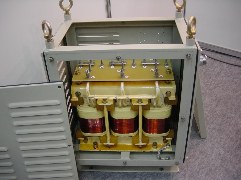
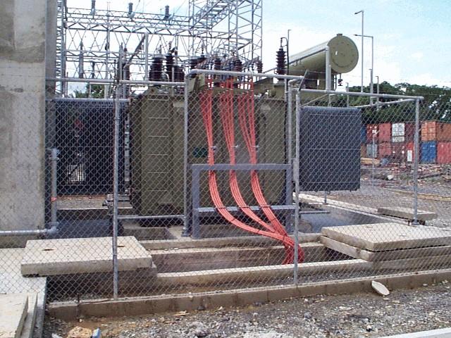
5 Service Tranformer Service Tranformer 7 Service Tranformer 9 8 Ditribution Tranformer 0 5


6 Ditribution Tranformer Tranmiion Tranformer Low power Tranformer Why do we need tranformer? 3 Step up ncreae voltage of generator output Generator output ~ 000 V Tranmit high power at low current (up to 765kV) Reduce cot of tranmiion ytem, becaue Reduce tranmiion loe ( R loe) Step down to adjut voltage to a uable level Create electrical iolation 4 6
7 nput Power (P in ) Stator Loe: Copper loe (P cu ) Core loe (P iron ) Airgap Power (P g ) Objective: Determine Motor Loe & Efficiency Baic Tranformer Model ron Core Rotor Copper Loe (P cu ) Developed Power (P d ) Rotational Loe (P rotational ) Output Power (P out ) 5 6 e dφ dt i i e e e dφ dt V Tranformer Equivalent Circuit What doe each circuit element repreent? ' R X R X R c X c c E E V load Primary Secondary 7 E E V V ' 8 7
 X c V R c X c E Equivalent to tranformer econdary winding 3 Equivalent to tranformer primary winding & core Equivalent to tranformer load 33 8")
8 Squirrel Cage M nduction Motor Equivalent Circuit (at Stand Still) R X X R c r V R c X c E E E E 9 30 nduction Motor Equivalent Circuit (Stator Circuit) R X R R X c V R c X c E E R ' ( ) X c V R c X c E Equivalent to tranformer econdary winding 3 Equivalent to tranformer primary winding & core Equivalent to tranformer load 33 8
9 nput Power (P in ) Loe & Efficiency Pin 3 V coθ R X X R m E E R ' V Rm Xm ( ) Stator Loe: Copper loe (P cu ) Core loe (P iron ) Rotor Copper Loe (P cu ) Airgap Power (P g ) Developed Power (P d ) ' Pcu 3 R ' R P g 3 ( ) Td ω V Piron 3 Rm cu ' ' ( ) R Pg P 3 ' ' R ( ) ( ) P ( T ω P d 3 g ) d Rotational Loe (P rotational ) Output Power (P out ) P rotational P out T ω Example Solution A 50 hp, 60 Hz, three-phae induction motor operate at full load at a peed of 764rpm. v.34hp kw The rotational loe of the motor are 950 W, the tator copper loe are.6 kw and the iron loe are. kw. Compute the motor efficiency. 50 P out.34 f n 0 p 37.3 kw ß hp to kw converion pole machine ha n 3600 rev/min 4 pole machine ha n 800 rev/min 6 pole machine ha n 00 rev/min 8 pole machine ha n 900 rev/min n 764. Since the lip i very mall, n 800 rev/min n n n
10 P P + P + in g cu P iron kw P iron. P d P cu.6 P g 39 kw P cu P g η P P out in.89 or 89% P P + d out P rotational kw Starting nduction Motor..5 Problem: Low tarting torque (relative to full-load T) High tarting current (relative to full-load ) Why are thee problem? 0 Small Slip Maximum Torque max P rotational P out kw 39 Large Slip T t T max Torque 40 Summary Sytem f coupling generator to end-ue (motor) Tranformer Operation Equivalent circuit nduction Motor Slip, and teady-tate motor peed Speed-torque relationhip Equivalent circuit Starting induction motor 4 0
ECE 325 Electric Energy System Components 6- Three-Phase Induction Motors. Instructor: Kai Sun Fall 2015
 ECE 35 Electric Energy Sytem Component 6- Three-Phae Induction Motor Intructor: Kai Sun Fall 015 1 Content (Material are from Chapter 13-15) Component and baic principle Selection and application Equivalent
Section Induction motor drives
 Section 5.1 - nduction motor drive Electric Drive Sytem 5.1.1. ntroduction he AC induction motor i by far the mot widely ued motor in the indutry. raditionally, it ha been ued in contant and lowly variable-peed
BASIC INDUCTION MOTOR CONCEPTS
 INDUCTION MOTOS An induction motor ha the ame phyical tator a a ynchronou machine, with a different rotor contruction. There are two different type of induction motor rotor which can be placed inide the
Basic parts of an AC motor : rotor, stator, The stator and the rotor are electrical
 INDUCTION MOTO 1 CONSTUCTION Baic part of an AC motor : rotor, tator, encloure The tator and the rotor are electrical circuit that perform a electromagnet. CONSTUCTION (tator) The tator - tationary part
Lecture Set 8 Induction Machines
 Lecture Set 8 Induction Machine S.D. Sudhoff Spring 2018 Reading Chapter 6, Electromechanical Motion Device, Section 6.1-6.9, 6.12 2 Sample Application Low Power: Shaded pole machine (mall fan) Permanent
No-load And Blocked Rotor Test On An Induction Machine
 No-load And Blocked Rotor Tet On An Induction Machine Aim To etimate magnetization and leakage impedance parameter of induction machine uing no-load and blocked rotor tet Theory An induction machine in
60 p. 2. A 200hp 600V, 60 Hz 3-phase induction motor has start code F. What line current should be expected at starting? 4 marks.
 EE 004 Final Solution : Thi wa a hr exam. A 60 Hz 4 pole -phae induction motor rotate at 740rpm. a) What i the lip? mark b) What i the peed o rotation o the rotor magnetic ield (in rpm)? mark The motor
Synchronous Machines - Structure
 Synchronou Machine - Structure Synchronou Machine - Structure rotate at contant peed. primary energy converion device of the word electric power ytem. both generator and motor operation can draw either
15 Problem 1. 3 a Draw the equivalent circuit diagram of the synchronous machine. 2 b What is the expected synchronous speed of the machine?
 Exam Electrical Machine and Drive (ET4117) 6 November 009 from 9.00 to 1.00. Thi exam conit of 4 problem on 4 page. Page 5 can be ued to anwer problem quetion b. The number before a quetion indicate how
University of Jordan Faculty of Engineering & Technology Electric Power Engineering Department
 University of Jordan Faculty of Engineering & Technology Electric Power Engineering Department EE471: Electrical Machines-II Tutorial # 2: 3-ph Induction Motor/Generator Question #1 A 100 hp, 60-Hz, three-phase
Induction Motor Drive
 Induction Motor Drive 1. Brief review of IM theory.. IM drive characteritic with: Variable input voltage Variable rotor reitance Variable rotor power Variable voltage and variable frequency, VVVF drive
Lecture (20) DC Machine Examples Start of Synchronous Machines
 DC Machine Examples Start of Synchronous Machines") Lecture (20) DC Machine Examples Start of Synchronous Machines Energy Systems Research Laboratory, FIU All rights reserved. 20-1 Energy Systems Research Laboratory, FIU All rights reserved. 20-2 Ra R f
Lecture (20) DC Machine Examples Start of Synchronous Machines Energy Systems Research Laboratory, FIU All rights reserved. 20-1 Energy Systems Research Laboratory, FIU All rights reserved. 20-2 Ra R f
Lesson 17: Synchronous Machines
 Lesson 17: Synchronous Machines ET 332b Ac Motors, Generators and Power Systems Lesson 17_et332b.pptx 1 Learning Objectives After this presentation you will be able to: Explain how synchronous machines
Chapter 4. Synchronous Generators. Basic Topology
 Basic Topology Chapter 4 ynchronous Generators In stator, a three-phase winding similar to the one described in chapter 4. ince the main voltage is induced in this winding, it is also called armature winding.
JRE SCHOOL OF Engineering
 JRE SCHOOL OF Engineering Class Test-1 Examinations September 2014 Subject Name Electromechanical Energy Conversion-II Subject Code EEE -501 Roll No. of Student Max Marks 30 Marks Max Duration 1 hour Date
Representation of a Group of Three-phase Induction Motors Using Per Unit Aggregation Model A.Kunakorn and T.Banyatnopparat
 epreentation of a Group of Three-phae Induction Motor Uing Per Unit Aggregation Model A.Kunakorn and T.Banyatnopparat Abtract--Thi paper preent a per unit gregation model for repreenting a group of three-phae
Prince Sattam bin Abdulaziz University College of Engineering. Electrical Engineering Department EE 3360 Electrical Machines (II)
") Chapter # 4 Three-Phase Induction Machines 1- Introduction (General Principles) Generally, conversion of electrical power into mechanical power takes place in the rotating part of an electric motor. In
Chapter # 4 Three-Phase Induction Machines 1- Introduction (General Principles) Generally, conversion of electrical power into mechanical power takes place in the rotating part of an electric motor. In
Electric Machines I Three Phase Induction Motor. Dr. Firas Obeidat
 Electric Machines I Three Phase Induction Motor Dr. Firas Obeidat 1 Table of contents 1 General Principles 2 Construction 3 Production of Rotating Field 4 Why Does the Rotor Rotate 5 The Slip and Rotor
Performance Improvement of Direct Torque Controlled Interior Permanent Magnet Synchronous Motor Drive by Considering Magnetic Saturation
 Performance Improvement of Direct Torque Controlled Interior Permanent Magnet Synchronou Motor Drive by Conidering Magnetic Saturation Behrooz Majidi * Jafar Milimonfared * Kaveh Malekian * *Amirkabir
Chapter 5 Three phase induction machine (1) Shengnan Li
 Shengnan Li") Chapter 5 Three phase induction machine (1) Shengnan Li Main content Structure of three phase induction motor Operating principle of three phase induction motor Rotating magnetic field Graphical representation
Chapter 5 Three phase induction machine (1) Shengnan Li Main content Structure of three phase induction motor Operating principle of three phase induction motor Rotating magnetic field Graphical representation
INDUCTION MOTOR MODEL AND PARAMETERS
 APPENDIX C INDUCTION MOTOR MODEL AND PARAMETERS C.1 Dynamic Model of the Induction Motor in Stationary Reference Frame A three phase induction machine can be represented by an equivalent two phase machine
Revision Guide for Chapter 15
 Revision Guide for Chapter 15 Contents tudent s Checklist Revision otes Transformer... 4 Electromagnetic induction... 4 Generator... 5 Electric motor... 6 Magnetic field... 8 Magnetic flux... 9 Force on
UNIT I INTRODUCTION Part A- Two marks questions
 ROEVER COLLEGE OF ENGINEERING & TECHNOLOGY ELAMBALUR, PERAMBALUR-621220 DEPARTMENT OF ELECTRICAL AND ELECTRONICS ENGINEERING DESIGN OF ELECTRICAL MACHINES UNIT I INTRODUCTION 1. Define specific magnetic
The Influence of the Load Condition upon the Radial Distribution of Electromagnetic Vibration and Noise in a Three-Phase Squirrel-Cage Induction Motor
 The Influence of the Load Condition upon the Radial Ditribution of Electromagnetic Vibration and Noie in a Three-Phae Squirrel-Cage Induction Motor Yuta Sato 1, Iao Hirotuka 1, Kazuo Tuboi 1, Maanori Nakamura
ROEVER COLLEGE OF ENGINEERING & TECHNOLOGY ELAMBALUR, PERAMBALUR DEPARTMENT OF ELECTRICAL AND ELECTRONICS ENGINEERING ELECTRICAL MACHINES I
 ROEVER COLLEGE OF ENGINEERING & TECHNOLOGY ELAMBALUR, PERAMBALUR-621220 DEPARTMENT OF ELECTRICAL AND ELECTRONICS ENGINEERING ELECTRICAL MACHINES I Unit I Introduction 1. What are the three basic types
Induction Motors. The single-phase induction motor is the most frequently used motor in the world
 Induction Motor The single-phase induction motor is the most frequently used motor in the world Most appliances, such as washing machines and refrigerators, use a single-phase induction machine Highly
An Introduction to Electrical Machines. P. Di Barba, University of Pavia, Italy
 An Introduction to Electrical Machines P. Di Barba, University of Pavia, Italy Academic year 0-0 Contents Transformer. An overview of the device. Principle of operation of a single-phase transformer 3.
Mutual Inductance. The field lines flow from a + charge to a - change
 Capacitors Mutual Inductance Since electrical charges do exist, electric field lines have a starting point and an ending point. For example, if you have a + and a - change, the field lines would look something
What lies between Δx E, which represents the steam valve, and ΔP M, which is the mechanical power into the synchronous machine?
 A 2.0 Introduction In the lat et of note, we developed a model of the peed governing mechanim, which i given below: xˆ K ( Pˆ ˆ) E () In thee note, we want to extend thi model o that it relate the actual
Dynamic Simulation of a Three-Phase Induction Motor Using Matlab Simulink
 Dynamic Simulation of a ThreePhae Induction Motor Uing Matlab Simulink Adel Aktaibi & Daw Ghanim, graduate tudent member, IEEE, M. A. Rahman, life fellow, IEEE, Faculty of Engineering and Applied Science,
DC Shunt Excited Motor
 A DC motor has DC hunt Excited Motor A constant (DC) magnetic field for the stator, and A constant (DC) magnetic field in the rotor, That switches as the motor rotates. This switching results in a constant
Electromagnetic Energy Conversion Exam 98-Elec-A6 Spring 2002
 Front Page Electromagnetic Energy Conversion Exam 98-Elec-A6 Spring 2002 Notes: Attempt question 1 and FOUR (4) other questions (FVE (5) questions in all). Unless you indicate otherwise, the first five
Overview Electrical Machines and Drives
 Overview Electrical Machine and Drive 7-9 1: Introduction, Maxwell equation, magnetic circuit 11-9 1.-3: Magnetic circuit, Princile 14-9 3-4.: Princile, DC machine 18-9 4.3-4.7: DC machine and drive 1-9
Physics 2. Angular Momentum. Prepared by Vince Zaccone For Campus Learning Assistance Services at UCSB
 Phyic Angular Momentum For Campu earning Angular Momentum Thi i the rotational equivalent of linear momentum. t quantifie the momentum of a rotating object, or ytem of object. To get the angular momentum,
FUNDAMENTALS OF POWER SYSTEMS
 1 FUNDAMENTALS OF POWER SYSTEMS 1 Chapter FUNDAMENTALS OF POWER SYSTEMS INTRODUCTION The three baic element of electrical engineering are reitor, inductor and capacitor. The reitor conume ohmic or diipative
Estimation of Temperature Rise in Stator Winding and Rotor Magnet of PMSM Based on EKF
 2010 3rd International Conference on Computer and Electrical Engineering (ICCEE 2010) IPCSIT vol. 53 (2012) (2012) IACSIT Pre, Singapore DOI: 10.7763/IPCSIT.2012.V53.No.2.37 Etimation of Temperature Rie
Parameter Estimation of Three Phase Squirrel Cage Induction Motor
 International Conference On Emerging Trends in Mechanical and Electrical Engineering RESEARCH ARTICLE OPEN ACCESS Parameter Estimation of Three Phase Squirrel Cage Induction Motor Sonakshi Gupta Department
CHAPTER 5 SIMULATION AND TEST SETUP FOR FAULT ANALYSIS
 47 CHAPTER 5 SIMULATION AND TEST SETUP FOR FAULT ANALYSIS 5.1 INTRODUCTION This chapter describes the simulation model and experimental set up used for the fault analysis. For the simulation set up, the
Massachusetts Institute of Technology Department of Electrical Engineering and Computer Science Electric Machines
 Massachusetts Institute of Technology Department of Electrical Engineering and Computer Science 6.685 Electric Machines Problem Set 10 Issued November 11, 2013 Due November 20, 2013 Problem 1: Permanent
9. Operation Principle of the Electric Machines
 9. Operation Principle of the Electric Machines J Electric Machines Operation Principle Ø An electric achine consists of two electric circuits coupled by eans of a agnetic flu, that is linked with both
EEE3405 ELECTRICAL ENGINEERING PRINCIPLES 2 - TEST
 ATTEMPT ALL QUESTIONS (EACH QUESTION 20 Marks, FULL MAKS = 60) Given v 1 = 100 sin(100πt+π/6) (i) Find the MS, period and the frequency of v 1 (ii) If v 2 =75sin(100πt-π/10) find V 1, V 2, 2V 1 -V 2 (phasor)
Definition Application of electrical machines Electromagnetism: review Analogies between electric and magnetic circuits Faraday s Law Electromagnetic
 Definition Application of electrical machines Electromagnetism: review Analogies between electric and magnetic circuits Faraday s Law Electromagnetic Force Motor action Generator action Types and parts
Simulation and Analysis of Linear Permanent Magnet Vernier Motors for Direct Drive Systems
 Available online at www.ijpe-online.com vol. 3, no. 8, December 07, pp. 304-3 DOI: 0.3940/ijpe.7.08.p.3043 Simulation and Analyi of Linear Permanent Magnet Vernier Motor for Direct Drive Sytem Mingjie
Revision Guide for Chapter 15
 Revision Guide for Chapter 15 Contents Revision Checklist Revision otes Transformer...4 Electromagnetic induction...4 Lenz's law...5 Generator...6 Electric motor...7 Magnetic field...9 Magnetic flux...
MATHEMATICAL MODELING OF INDUCTION MOTORS
 37 CHAPTER 3 MATHEMATICAL MODELING OF INDUCTION MOTORS To tart with, a well-known technique called the SVPWM technique i dicued a thi form the bai of the mathematical modeling of IM. Furthermore, the d
Sensorless PM Brushless Drives
 IEEE UK Chapter Seminar 15 December 3 Senorle PM Bruhle Drive Prof. D. Howe and Prof. Z. Q. Zhu The Univerity of Sheffield Electrical Machine & Drive Reearch Group Outline Review of enorle technique Zero-croing
3 d Calculate the product of the motor constant and the pole flux KΦ in this operating point. 2 e Calculate the torque.
 Exam Electrical Machines and Drives (ET4117) 11 November 011 from 14.00 to 17.00. This exam consists of 5 problems on 4 pages. Page 5 can be used to answer problem 4 question b. The number before a question
Control of Wind Turbine Generators. James Cale Guest Lecturer EE 566, Fall Semester 2014 Colorado State University
 Control of Wind Turbine Generators James Cale Guest Lecturer EE 566, Fall Semester 2014 Colorado State University Review from Day 1 Review Last time, we started with basic concepts from physics such as
LAB REPORT: THREE-PHASE INDUCTION MACHINE
 LAB REPORT: THREE-PHASE INDUCTION MACHINE ANDY BENNETT 1. Summary This report details the operation, modelling and characteristics of a three-phase induction machine. It attempts to provide a concise overview
13. Faraday s Law. S. G. Rajeev. March 3, 2009
 13. Faraday s Law S. G. Rajeev March 3, 009 1 Electromotive Force If a coil moves (or rotates) near a magnet, a current in induced on it, even if it is not connected to a battery. That means an electric
Sensorless PMSM Field Oriented Control Solution Based on TI Cortex-M3
 Senorle PMSM Field Oriented Control Solution Baed on TI Cortex-M3 AEDS Team Technical Service Arrow Steven Wang Agenda Permanent Magnet Synchronou Motor Field Oriented Control Realization Senorle Control
ISSN: [Basnet* et al., 6(3): March, 2017] Impact Factor: 4.116
![ISSN: [Basnet* et al., 6(3): March, 2017] Impact Factor: 4.116](/thumbs/95/123902996.jpg "ISSN: [Basnet* et al., 6(3): March, 2017] Impact Factor: 4.116") IJESR INERNAIONAL JOURNAL OF ENGINEERING SCIENCES & RESEARCH ECHNOLOGY DIREC ORQUE CONROLLED INDUCION MOOR DRIVE FOR ORQUE RIPPLE REDUCION Bigyan Banet Department of Electrical Engineering, ribhuvan Univerity,
IJESR INERNAIONAL JOURNAL OF ENGINEERING SCIENCES & RESEARCH ECHNOLOGY DIREC ORQUE CONROLLED INDUCION MOOR DRIVE FOR ORQUE RIPPLE REDUCION Bigyan Banet Department of Electrical Engineering, ribhuvan Univerity,
PROBLEM SOLUTIONS: Chapter 4
 48 PROBLEM SOLUTIONS: Chapter 4 Problem 4.1 ω m = 100 π/30 = 40π rad/sec part (b): 60 Hz; 10π rad/sec part (c): 100 5/6 = 1000 r/min Problem 4. The voltages in the remaining two phases can be expressed
Generators for wind power conversion
 Generators for wind power conversion B. G. Fernandes Department of Electrical Engineering Indian Institute of Technology, Bombay Email : bgf@ee.iitb.ac.in Outline of The Talk Introduction Constant speed
Q.1 A) Attempt any three of the following: 12 Marks i) State why three phase induction motor never run on synchronous speed? Ans:
 Attempt any three of the following: 12 Marks i) State why three phase induction motor never run on synchronous speed? Ans:") (IO/IEC-700-005 Certified) WINTER 04 Examinations ubject Code: 75 Model Answer Page of 33 Important suggestions to examiners: ) The answers should be examined by key words and not as word-to-word as given
(IO/IEC-700-005 Certified) WINTER 04 Examinations ubject Code: 75 Model Answer Page of 33 Important suggestions to examiners: ) The answers should be examined by key words and not as word-to-word as given
Homework #7 Solution. Solutions: ΔP L Δω. Fig. 1
 Homework #7 Solution Aignment:. through.6 Bergen & Vittal. M Solution: Modified Equation.6 becaue gen. peed not fed back * M (.0rad / MW ec)(00mw) rad /ec peed ( ) (60) 9.55r. p. m. 3600 ( 9.55) 3590.45r.
Measurements of a 37 kw induction motor. Rated values Voltage 400 V Current 72 A Frequency 50 Hz Power 37 kw Connection Star
 Measurements of a 37 kw induction motor Rated values Voltage 4 V Current 72 A Frequency 5 Hz Power 37 kw Connection Star Losses of a loaded machine Voltage, current and power P = P -w T loss in Torque
Physics 6A. Angular Momentum. Prepared by Vince Zaccone For Campus Learning Assistance Services at UCSB
 Phyic 6A Angular Momentum For Campu earning Angular Momentum Thi i the rotational equivalent of linear momentum. t quantifie the momentum of a rotating object, or ytem of object. f we imply tranlate the
Synchronous Machines
 Synchronous machine 1. Construction Generator Exciter View of a twopole round rotor generator and exciter. A Stator with laminated iron core C Slots with phase winding B A B Rotor with dc winding B N S
Three Phase Induction Motors
 Chapter (8) hree Phae Induction Motor Introduction he three-phae induction otor are the ot widely ued electric otor in indutry. hey run at eentially contant peed fro no-load to full-load. However, the
6 Chapter 6 Testing and Evaluation
 6 Chapter 6 Testing and Evaluation n this chapter the results obtained during the testing of the LS PMSM prototype are provided. The test results are compared with Weg s LS PMSM machine, WQuattro. The
Synchronous Machines
 Synchronous Machines Synchronous generators or alternators are used to convert mechanical power derived from steam, gas, or hydraulic-turbine to ac electric power Synchronous generators are the primary
ME 375 FINAL EXAM Wednesday, May 6, 2009
 ME 375 FINAL EXAM Wedneday, May 6, 9 Diviion Meckl :3 / Adam :3 (circle one) Name_ Intruction () Thi i a cloed book examination, but you are allowed three ingle-ided 8.5 crib heet. A calculator i NOT allowed.
MODELING AND HIGH-PERFORMANCE CONTROL OF ELECTRIC MACHINES
 MODELING AND HIGH-PERFORMANCE CONTROL OF ELECTRIC MACHINES JOHN CHIASSON IEEE PRESS ü t SERIES ON POWER ENGINEERING IEEE Press Series on Power Engineering Mohamed E. El-Hawary, Series Editor The Institute
Generators. What its all about
 Generators What its all about How do we make a generator? Synchronous Operation Rotor Magnetic Field Stator Magnetic Field Forces and Magnetic Fields Force Between Fields Motoring Generators & motors are
Electrical Machines and Energy Systems: Operating Principles (Part 1) SYED A Rizvi
 SYED A Rizvi") Electrical Machines and Energy Systems: Operating Principles (Part 1) SYED A Rizvi AC Machines Operating Principles: Rotating Magnetic Field The key to the functioning of AC machines is the rotating magnetic
Electrical Machines and Energy Systems: Operating Principles (Part 1) SYED A Rizvi AC Machines Operating Principles: Rotating Magnetic Field The key to the functioning of AC machines is the rotating magnetic
PESIT Bangalore South Campus Hosur road, 1km before Electronic City, Bengaluru -100 Department of Electronics & Communication Engineering
 QUESTION PAPER INTERNAL ASSESSMENT TEST 2 Date : /10/2016 Marks: 0 Subject & Code: BASIC ELECTRICAL ENGINEERING -15ELE15 Sec : F,G,H,I,J,K Name of faculty : Dhanashree Bhate, Hema B, Prashanth V Time :
Question 1 Equivalent Circuits
 MAE 40 inear ircuit Fall 2007 Final Intruction ) Thi exam i open book You may ue whatever written material you chooe, including your cla note and textbook You may ue a hand calculator with no communication
An Improved Flux Observer for Sensorless Permanent Magnet Synchronous Motor Drives with Parameter Identification
 J Electr Eng Technol Vol. 8, No. 3: 516-53, 13 http://dx.doi.org/1.537/jeet.13.8.3.516 ISSN(Print) 1975-1 ISSN(Online) 93-743 An Improved Flux Oberver for Senorle Permanent Magnet Synchronou Motor Drive
Simulink Implementation of Induction Machine Model A Modular Approach
 Simulink Implementation of Induction Machine Model A Modular Approach Burak Ozpineci burak@ieee.org Oak Ridge National Laboratory P.O. Box 9 Oak Ridge, TN 78-67 Abtract - In thi paper, a modular Simulink
Synchronous machine with PM excitation Two-axis model
 Synchronous machine with PM excitation q Two-axis model q i q u q d i Q d Q D i d N S i D u d Voltage, flux-linkage and motion equations for a PM synchronous machine dd ud Ri s d q dt dq uq Ri s q d dt
AN EFFICIENT APPROACH FOR ANALYSIS OF ISOLATED SELF EXCITED INDUCTION GENERATOR
 AN EFFICIENT APPROACH FOR ANALYSIS OF ISOLATED SELF EXCITED INDUCTION GENERATOR Deepika 1, Pankaj Mehara Assistant Professor, Dept. of EE, DCRUST, Murthal, India 1 PG Student, Dept. of EE, DCRUST, Murthal,
Sensorless speed control including zero speed of non salient PM synchronous drives
 BULLETIN OF THE POLISH ACADEMY OF SCIENCES TECHNICAL SCIENCES Vol. 54, No. 3, 2006 Senorle peed control including zero peed of non alient PM ynchronou drive H. RASMUSSEN Aalborg Univerity, Fredrik Bajer
ECE 325 Electric Energy System Components 7- Synchronous Machines. Instructor: Kai Sun Fall 2015
 ECE 325 Electric Energy System Components 7- Synchronous Machines Instructor: Kai Sun Fall 2015 1 Content (Materials are from Chapters 16-17) Synchronous Generators Synchronous Motors 2 Synchronous Generators
ECEN 667 Power System Stability Lecture 18: Voltage Stability, Load Models
 ECEN 667 Power System Stability Lecture 18: Voltage Stability, Load Models Prof. Tom Overbye Dept. of Electrical and Computer Engineering Texas A&M University, overbye@tamu.edu 1 Announcements Read Chapter
ELECTRICALMACHINES-I QUESTUION BANK
 ELECTRICALMACHINES-I QUESTUION BANK UNIT-I INTRODUCTION OF MAGNETIC MATERIAL PART A 1. What are the three basic rotating Electric machines? 2. Name the three materials used in machine manufacture. 3. What
Comparison of Hardware Tests with SIMULINK Models of UW Microgrid
 Comparion of Hardware Tet with SIMULINK Model of UW Microgrid Introduction Thi report include a detailed dicuion of the microource available on the Univerity- of- Wiconin microgrid. Thi include detail
Physics 169. Luis anchordoqui. Kitt Peak National Observatory. Monday, March 27, 17
 Physics 169 Kitt Peak National Observatory Luis anchordoqui 1 Question teady electric current can give steady magnetic field Because of symmetry between electricity and magnetism we can ask: teady magnetic
Automatic Control Systems. -Lecture Note 15-
 -Lecture Note 15- Modeling of Physical Systems 5 1/52 AC Motors AC Motors Classification i) Induction Motor (Asynchronous Motor) ii) Synchronous Motor 2/52 Advantages of AC Motors i) Cost-effective ii)
Lecture 4. Chapter 11 Nise. Controller Design via Frequency Response. G. Hovland 2004
 METR4200 Advanced Control Lecture 4 Chapter Nie Controller Deign via Frequency Repone G. Hovland 2004 Deign Goal Tranient repone via imple gain adjutment Cacade compenator to improve teady-tate error Cacade
Motor Info on the WWW Motorola Motors DC motor» /MOTORDCTUT.
 Motor Info on the WWW Motorola Motors DC motor» http://www.freescale.com/files/microcontrollers/doc/train_ref_material /MOTORDCTUT.html Brushless DC motor» http://www.freescale.com/files/microcontrollers/doc/train_ref_material
A Novel Direct Torque Control Scheme for Induction Machines With Space Vector Modulation
 24 35th Annual IEEE Power Electronic Specialit Conference Aachen, Germany, 24 A Novel Direct Torque Control Scheme for Induction Machine With Space Vector Modulation Joé Rodríguez, Jorge Pontt, Céar Silva,
Open Access Study of Direct Torque Control Scheme for Induction Motor Based on Torque Angle Closed-Loop Control. Xuande Ji *, Daqing He and Yunwang Ge
 Send Order for Reprint to reprint@benthamcience.ae 6 The Open Electrical & Electronic Engineering Journal, 25, 9, 669 Open Acce Study of Direct Torque Control Scheme for Induction Motor Baed on Torque
Identification of Short-circuit and Induction Motor Starting Events on Power Systems Monitoring and Protection Using Instantaneous Space Vectors
 1 dentification of Short-circuit and nduction Motor Starting Event on Power Sytem Monitoring and Protection Uing ntantaneou Space Vector D. L. Milanez Abtract hi document preent the application of recently
: 2 : EE-Conventional Test-10 (Solutions)
") .(a) Sol: The hunt field current At no load, armature current ounter e.m.f, E a I f I a. A 5 A 9.4 : : EE-onventional Tet- (Solution) otational loe = E al I a 9.4 58. watt At full load, armature current
.(a) Sol: The hunt field current At no load, armature current ounter e.m.f, E a I f I a. A 5 A 9.4 : : EE-onventional Tet- (Solution) otational loe = E al I a 9.4 58. watt At full load, armature current
Texas A & M University Department of Mechanical Engineering MEEN 364 Dynamic Systems and Controls Dr. Alexander G. Parlos
 Texas A & M University Department of Mechanical Engineering MEEN 364 Dynamic Systems and Controls Dr. Alexander G. Parlos Lecture 6: Modeling of Electromechanical Systems Principles of Motor Operation
EE 742 Chapter 3: Power System in the Steady State. Y. Baghzouz
 EE 742 Chapter 3: Power System in the Steady State Y. Baghzouz Transmission Line Model Distributed Parameter Model: Terminal Voltage/Current Relations: Characteristic impedance: Propagation constant: π
EC T32 - ELECTRICAL ENGINEERING
 EC T32 - ELECTRICAL ENGINEERING UNIT-I - TRANSFORMER 1. What is a transformer? 2. Briefly explain the principle of operation of transformers. 3. What are the parts of a transformer? 4. What are the types
INFLUENCE OF BROKEN ROTOR BARS LOCATION IN THE SQUIRREL CAGE INDUCTION MOTOR USING FINITE ELEMENT METHOD
 Journal of Fundamental and Applied Science ISSN - Available online at http:www.jfa.info INFLUENCE OF BROKEN ROTOR BARS LOCATION IN THE SQUIRREL CAGE INDUCTION MOTOR USING FINITE ELEMENT METHOD N. Halem*,
Direct Torque Control of Saturated Induction Machine with and without speed sensor
 Journal of Advanced Reearch in Science and Technology ISSN: 2352-9989 Direct Torque Control of Saturated Induction Machine with and without peed enor Tahar Djellouli,2, Samir Moulahoum, Med Seghir Boucherit
Step Motor Modeling. Step Motor Modeling K. Craig 1
 Step Motor Modeling Step Motor Modeling K. Craig 1 Stepper Motor Models Under steady operation at low speeds, we usually do not need to differentiate between VR motors and PM motors (a hybrid motor is
UNIVERSITY OF SWAZILAND FACULTY OF SCIENCE DEPARTMENT OF ELECTRICAL AND ELECTRONIC ENGINEERING. MAIN EXAMINATION May 2013
 UNIVERSITY OF SWAZILAND FACULTY OF SCIENCE DEPARTMENT OF ELECTRICAL AND ELECTRONIC ENGINEERING MAIN EXAMINATION May 2013 TITLE OF PAPER: Fundamentals of Power Engineering COURSE CODE: EE 351 TIME ALLOWED:
AC Circuits Homework Set
 Problem 1. In an oscillating LC circuit in which C=4.0 μf, the maximum potential difference across the capacitor during the oscillations is 1.50 V and the maximum current through the inductor is 50.0 ma.
Electrical Machines and Energy Systems: Operating Principles (Part 2) SYED A Rizvi
 SYED A Rizvi") Electrical Machines and Energy Systems: Operating Principles (Part 2) SYED A Rizvi AC Machines Operating Principles: Synchronous Motor In synchronous motors, the stator of the motor has a rotating magnetic
Electrical Machines and Energy Systems: Operating Principles (Part 2) SYED A Rizvi AC Machines Operating Principles: Synchronous Motor In synchronous motors, the stator of the motor has a rotating magnetic
Synchronous Machines
 Synchronous Machines Synchronous Machines n 1 Φ f n 1 Φ f I f I f I f damper (run-up) winding Stator: similar to induction (asynchronous) machine ( 3 phase windings that forms a rotational circular magnetic
ELG3311: Assignment 3
 LG33: ssignent 3 roble 6-: The Y-connected synchronous otor whose naeplate is shown in Figure 6- has a perunit synchronous reactance of 0.9 and a per-unit resistance of 0.0. (a What is the rated input
Lecture 9: Space-Vector Models
 1 / 30 Lecture 9: Space-Vector Models ELEC-E8405 Electric Drives (5 ECTS) Marko Hinkkanen Autumn 2017 2 / 30 Learning Outcomes After this lecture and exercises you will be able to: Include the number of
Introduction to Synchronous. Machines. Kevin Gaughan
 Introduction to Synchronous Machines Kevin Gaughan The Synchronous Machine An AC machine (generator or motor) with a stator winding (usually 3 phase) generating a rotating magnetic field and a rotor carrying
Fachgebiet Leistungselektronik und Elektrische Antriebstechnik. Test Examination: Mechatronics and Electrical Drives
 Prof. Dr. Ing. Joachim Böcker Test Examination: Mechatronics and Electrical Drives 8.1.214 First Name: Student number: Last Name: Course of Study: Exercise: 1 2 3 Total (Points) (2) (2) (2) (6) Duration:
Per Unit Analysis. Single-Phase systems
 Per Unit Analyi The per unit method of power ytem analyi eliminate the need for converion of voltae, current and impedance acro every tranformer in the circuit. n addition, the need to tranform from 3-