2016 Kappa Electronics Motor Control Training Series Kappa Electronics LLC. -V th. Dave Wilson Co-Owner Kappa Electronics.
|
|
|
- Felix Tucker
- 5 years ago
- Views:
Transcription


1 2016 Kappa Electronics Motor Control Training Series 2016 Kappa Electronics C V th CoOwner Kappa Electronics


2 Benefits of Field Oriented Control
3 NewtonMeters Maximum Torque Per Amp (MTPA) Maximum torque per amp (MTPA) 200V 200 V(treaction) V 100V 50V Simulated Reactance Torque as a function of angle delta from 2005 Prius Traction Motor 0 0V 50 50V V V o 200V 0.0s 0.3s 0.6s 0.9s 1.2s 1.5s 1.8s 2.1s 2.4s 2.7s 3.0s 3.3s 3.6s 150 o 120 o 90 o 60 o 30 o 0 o 30 o 60 o 90 o 120 o 150 o 180 o


4 Field Oriented Control in Real Time A B C Torque Currents Constant 3 2 P 2 dr I qs Constant (for now) Adjustable Torque expression based on amplitude invariant form of Clarke Transform. Interrupt: Measure rotor flux angle Regulate current vector to be 90 o wrt rotor flux Exit ISR Interrupt: Measure new rotor flux angle Regulate current vector to be 90 o wrt rotor flux Exit ISR Interrupt: Measure new rotor flux angle Regulate current vector to be 90 o wrt rotor flux Exit ISR


5 Establishing Space Vector Conventions b B Direction of positive rotation Direction of positive speed Direction of positive torque a A a Phase A leads phase B Phase B leads phase C Phase C leads phase A C b Motor shaft axis


6 How Do You Control Torque on a DC Motor? Brush DC Motor Desired Current Error Signal PI Controller PWM Power Stage Dave s Motor Control Center Measured Current ADC1 Commutator keeps rotor and stator fields properly aligned! Measure current already flowing in the motor. Compare the measured current with the desired current, and generate an error signal. Amplify the error signal to generate a correction voltage. Modulate the correction voltage onto the motor terminals.
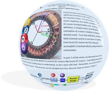
7 1. Measure currents already flowing in the motor. Only 2 phases are measured! WHY? A, B, and C axes are fixed with respect to the motor housing. This reference frame is also called the stationary frame or stator frame. net current vector B i a i b A i c (implied) B C Dave s Motor Control Center i b i c i a A Controller with A/D i a i b i c C
 i b = I m sin(q 120 o ) i c = I m sin(q 240 o ) I m is proportional to motor torque q is the angle")
8 2. Compare the measured current (vector) with the desired current (vector), and generate error signals. The desired phase currents can be calculated via these equations: i a = I m sin(q ) i b = I m sin(q 120 o ) i c = I m sin(q 240 o ) I m is proportional to motor torque q is the angle of the rotor flux B C Commanded i s i b i a Error i s i c A So how do we find q?
 with")
, and generate")


9 2. Compare the measured current (vector) with the desired current (vector), and generate error signals. q or q d Magnetic axis for phase A Usually accomplished with a resolver or encoder.
 Phase C PI i c I m sin(q 240 o")
10 3Phase Stationary Frame Current Regulators q = rotor flux angle Phase A PI i a V a I m sin(q ) Reference current waveforms synchronized to rotor position q Phase B PI i b V b V c I m sin(q 120 o ) Phase C PI i c I m sin(q 240 o )
11 2. Compare the measured current (vector) with the desired current (vector), and generate error signals. The CARKE transform allows us to convert three vectors into two orthogonal vectors that produce the same net vector. B i b i s i c i b In other words, A convert a 3phase i a i a motor into a 2phase motor. This is the Amplitude C Invariant form of the Forward Clarke Clarke Transform a(t) b(t) c(t) a b 1 a t 2 a t b( t) c( t ) b t bt ct 3
12 2Phase Stationary Frame Current Regulators V a 2phase to 3phase transform V b q V c Reference current waveforms synchronized to rotor position V α V β i B i C i A 3phase to 2phase transform i α i β Phase α PI Phase β PI

13 Stationary Frame Tracking

14 Synchronous Frame Tracking
15 2. Compare the measured current (vector) with the desired current (vector), and generate error signals. Jump up on the rotating reference frame, whose xaxis is the rotor flux axis. B i q i b i s i d This is called the Park Transform i a A q C a b i d i a cosq i b sinq i q i a sinq i b cosq
16 2. Compare the measured current (vector) with the desired current (vector), and generate error signals. i d i q and are handled independently. Since the comparison is performed in the synchronous frame, motor AC frequency is not seen. Thus, they are DC quantities! Under normal conditions, we have all the flux we need supplied by the permanent magnets on the rotor. So commanded i d is set to zero. i d (commanded) i d (measured) error d (t) This is how much torque we want! i q (commanded) i q (measured) error q (t) Since i d is directly aligned with the rotor flux, it can be used to control the effect of the rotor flux on the stator coils. i q controls the amount of torque generated by the motor
 Commanded I d Measured I d Error K a K b V d PI Controller (qaxis) Commanded I q Measured I q Error K a K b V q K a Current Bandwidth (rad /")
17 3. (Finally!) Amplify the error signals to generate correction voltages. PI Controller (daxis) Commanded I d Measured I d Error K a K b V d PI Controller (qaxis) Commanded I q Measured I q Error K a K b V q K a Current Bandwidth (rad / sec) K b Motor Rd Rq d q PMSM Rs Rs s s ACIM Rs RsRr, IPM Rs Rs s_d s_q R s 1 2 m r s s 1 2 m r s
18 4. Modulate the correction voltages onto the motor terminals. Before we can apply the voltages to the motor windings, we must first jump off of the rotating reference frame. B v b v q v d Voltage vector q v a A Part A. Transfer the voltage vectors back to the stationary rectangular coordinate system. C v d (t) v q (t) v v a b v v d d cosq sinq v v q q sinq cosq a b

19 4. Modulate the correction voltages onto the motor terminals. Part B. Next, we transform the voltage vectors from the rectangular coordinate system to three phase vectors. B v b v b v c v a v a Voltage Vector A C Reverse Clarke Transformation A a a b A B C B C a a b b
20 4. Modulate the correction voltages onto the motor terminals. Phase A top Phase A bottom Phase B top Phase B bottom Phase C top Phase C bottom Over time, under steadystate conditions, the correction voltages v a, v b, and v c will be sine waves phase shifted by 120 o.
21 FOC in a Nutshell V a Torque Current Wilson Flux Current q Reverse ClarkePark Transforms V b q V c V q V d i B i Forward C ClarkePark i A Transforms i q i d Desired Torque PI q Desired Flux PI


22 2016 Kappa Electronics Motor Control Training Series 2016 Kappa Electronics C V th Owner Kappa Electronics

23 ACIM Circuit Representation with Arbitrary Turns Ratio a r j s s a m 2 j a r a m ja m 2 a r r S General equivalent circuit showing arbitrary value of referral ratio a (a=1 corresponds to a turns ratio of N s /N r, which yields the conventional circuit.) If the real value of rotor current isn t required, a can be any value except zero or infinity, resulting in a multitude of possible circuits!
24 ACIM Circuit Representation with Turns Ratio a=m/r Torque current i q Rotor Flux current i d Stator current Rotor leakage inductor is gone! This implies that a reference frame exists where the stator current can be resolved into torque current and flux current. Source: Vector Control and Dynamics of AC Drives, by Don Novotny and Tom ipo, Oxford University Press, 2000
25 Torque Production in an ACIM Stator current is resolved into flux producing and torque producing components. i q Rotor flux is NOT fixed w.r.t. rotor. It is asynchronous to rotor position. i d i s T 3P m e m d q 4 rotor flux r P equals the number of poles 3 4 r m i i P id iq 2 r m i d Both i d and i q produce torque. So why is torque usually set by i q only? Hint: There are two reasons.
26 Dynamic Response of Rotor Referenced Field Orientation Step change in i q Step change in i d i qr m r i qs i qs i dr i qr i qs i qr i qs i ds i ds i ds dr Torque instantaneously changed. dr dr Torque slowly changed.


27 ACIM Flux Angle Calculation Dave s Motor Control Center Slip Calculator Encoder Commanded i d Commanded i q 1 1 St r t r N D ^ s r ^ q d B Recall that the rotor flux sweeps across the surface of the rotor at a speed equal to the slip frequency, i.e., it is asynchronous to the rotor. q d A C
28 Synchronous Frame Regulation i q and i d are still regulated independently. However, we now need a nonzero i d value, since the rotor doesn t produce any flux on its own (i.e., it doesn t have a permanent magnet) P i (commanded) d error(t) I i d (measured) v d i q (commanded) i q (measured) error(t) P I v q i d i q controls rotor flux magnitude. controls amount of torque generated by motor
 P I P V d V q Reverse")


29 P Commanded Rotor Speed Commanded i d (flux) Commanded i q (torque) P I P V d V q Reverse ClarkePark Transform θ d V a V b V c Dave s Motor Control Center I i d i q i a I Forward ClarkePark Transform θ d i b i c Commanded i d Commanded i q Slip Calculator Slip Frequency θ d Actual Rotor Speed Control Diagram of a Variable Speed Control System Utilizing Field Oriented Control.
30 Motor DQ Coupling 1/ d 1/ q
31 Stator Voltage Differential Equations Voltage equations from the block diagram: daxis qaxis V sd rs isd sq s dt isd sd K V sq rs isq sd s dt isq sq sq Taking the derivative of both sides: sd daxis qaxis V V sd sq r s r s i i sd sq sq sd s s sd sq d dt d dt i i sd sq Substituting for flux terms and rearranging: daxis V sd r s i sd sq i sq s sd d dt i sd 0 qaxis V sq r s i sq d i K i 0 sd sd s sq dt sq
32 Current Regulator Decoupling Permanent Magnet Motors Commanded i d K a V d K b i d V d compensation s i q Commanded i q V q compensation K a K b V q K E
33 Current Regulator Decoupling AC Induction Motors i d R r r m m / r s 2 m r V d compensation i q R r / r m / r V q compensation s 2 m r
34 Crosscoupling Effect with FOC Current Regulators Decoupling Compensation OFF Commanded Iq Actual Iq 400ms 420ms 440ms 460ms 480ms 500ms 520ms 540ms 560ms 580ms 600ms 620ms 640ms 660ms 680ms Decoupling Compensation ON Commanded Iq Actual Iq 400ms 420ms 440ms 460ms 480ms 500ms 520ms 540ms 560ms 580ms 600ms 620ms 640ms 660ms 680ms


35 2016 Kappa Electronics Motor Control Training Series 2016 Kappa Electronics C V th Owner Kappa Electronics

36 Flux is reluctant to jump through air because air has high permeability. i Reluctance Torque The magnet exerts force on the knife in an effort to minimize the reluctance of the flux path. N Torque S
37 Total Motor Torque I qs I ds Permanent Magnet Rotor Reaction Torque Reluctance Torque 3 P Torque driqs ds 2 2 qs I ds I qs Torque expression based on amplitude invariant form of Clarke Transform.

38 Buried Magnets Create NEW Torque Buried rotor magnets produce different inductances on the dq axes. This results in a NEW torque component proportional to the difference in these inductances.
39 CW CCW Torque ocked Rotor D Torque vs. Angle Q Q Reaction Torque (magnet to magnet) D D Stable Stable Unstable 0 o Unstable 45 o 90 o 135 o Unstable 180 o Q D Q Reluctance Torque (magnet to metal) The magnets exerts force on the rotor in an effort to minimize the resistance (reluctance) of the flux path.

40 Effect of Saliency on Optimum Torque Angle Positive I ds Negative I ds


41 MTPA Control of IPM Motors Commanded i d Commanded Speed Actual Speed imit i T i d 1 r 4 d q i d 2 r 8i 2 T d q 2 i d Current Controller V d Reverse ClarkePark Transform V a V b V c IPM Dave s Motor Control Center q 2 2 i i i i sign T T d Current Controller V q θ d Commanded i q d/dt i d i q i a Forward ClarkePark Transform i b i c θ d Rotor Flux Angle
2014 Texas Instruments Motor Control Training Series. -V th. Dave Wilson
 2014 Texas Instruments Motor Control Training Series V th NewtonMeters Maximum Torque Per Amp (MTPA) Maximum torque per amp (MTPA) 2 0 0 V 200 V (tr e a c ti o n ) 150 1 5 0 V 100 1 0 0 V 50 5 0 V Simulated
2014 Texas Instruments Motor Control Training Series. -V th. Dave Wilson
 204 Texas Instruments Motor Control Training Series V th Speed Sensorless FOC P Commanded Rotor Speed Commanded i d = 0 Commanded i q (torque) P I P V d V q Reverse ClarkePark Transform θ d V a V b V c
International Journal of Advance Engineering and Research Development SIMULATION OF FIELD ORIENTED CONTROL OF PERMANENT MAGNET SYNCHRONOUS MOTOR
 Scientific Journal of Impact Factor(SJIF): 3.134 e-issn(o): 2348-4470 p-issn(p): 2348-6406 International Journal of Advance Engineering and Research Development Volume 2,Issue 4, April -2015 SIMULATION
Digitization of Vector Control Algorithm Using FPGA
 Digitization of Vector Control Algorithm Using FPGA M. P. Priyadarshini[AP] 1, K. G. Dharani[AP] 2, D. Kavitha[AP] 3 DEPARTMENT OF ECE, MVJ COLLEGE OF ENGINEERING, BANGALORE Abstract: The paper is concerned
CHAPTER 2 MODELLING OF INTERIOR PERMANENT MAGNET SYNCHRONOUS MOTOR
 21 CHAPTER 2 MODELLING OF INTERIOR PERMANENT MAGNET SYNCHRONOUS MOTOR 2.1 INTRODUCTION The need for adjustable speed drives in industrial applications has been increasing progressively. The variable speed
Control of Wind Turbine Generators. James Cale Guest Lecturer EE 566, Fall Semester 2014 Colorado State University
 Control of Wind Turbine Generators James Cale Guest Lecturer EE 566, Fall Semester 2014 Colorado State University Review from Day 1 Review Last time, we started with basic concepts from physics such as
2016 Kappa Electronics Motor Control Training Series 2016 Kappa Electronics LLC. -V th. Dave Wilson Co-Owner Kappa Electronics.
 2016 Kappa Electronics Motor Control Training Series 2016 Kappa Electronics LLC V th CoOwner Kappa Electronics www.kappaiq.com Speed Sensorless FOC P Commanded Rotor Speed Commanded i d = 0 Commanded i
Mathematical Modelling of Permanent Magnet Synchronous Motor with Rotor Frame of Reference
 Mathematical Modelling of Permanent Magnet Synchronous Motor with Rotor Frame of Reference Mukesh C Chauhan 1, Hitesh R Khunt 2 1 P.G Student (Electrical),2 Electrical Department, AITS, rajkot 1 mcchauhan1@aits.edu.in
An Introduction to Electrical Machines. P. Di Barba, University of Pavia, Italy
 An Introduction to Electrical Machines P. Di Barba, University of Pavia, Italy Academic year 0-0 Contents Transformer. An overview of the device. Principle of operation of a single-phase transformer 3.
Lesson 17: Synchronous Machines
 Lesson 17: Synchronous Machines ET 332b Ac Motors, Generators and Power Systems Lesson 17_et332b.pptx 1 Learning Objectives After this presentation you will be able to: Explain how synchronous machines
JRE SCHOOL OF Engineering
 JRE SCHOOL OF Engineering Class Test-1 Examinations September 2014 Subject Name Electromechanical Energy Conversion-II Subject Code EEE -501 Roll No. of Student Max Marks 30 Marks Max Duration 1 hour Date
Massachusetts Institute of Technology Department of Electrical Engineering and Computer Science Electric Machines
 Massachusetts Institute of Technology Department of Electrical Engineering and Computer Science 6.685 Electric Machines Problem Set 10 Issued November 11, 2013 Due November 20, 2013 Problem 1: Permanent
REAL TIME CONTROL OF DOUBLY FED INDUCTION GENERATOR. Benmeziane Meriem, Zebirate Soraya, Chaker Abelkader Laboratory SCAMRE, ENPO, Oran, Algeria
 REAL TIME CONTROL OF DOUBLY FED INDUCTION GENERATOR Benmeziane Meriem, Zebirate Soraya, Chaker Abelkader Laboratory SCAMRE, ENPO, Oran, Algeria This paper presents a real time simulation method of wind
Comparison Between Direct and Indirect Field Oriented Control of Induction Motor
 Comparison Between Direct and Indirect Field Oriented Control of Induction Motor Venu Gopal B T Research Scholar, Department of Electrical Engineering UVCE, Bangalore University, Bengaluru ABSTRACT - Vector
INDUCTION MOTOR MODEL AND PARAMETERS
 APPENDIX C INDUCTION MOTOR MODEL AND PARAMETERS C.1 Dynamic Model of the Induction Motor in Stationary Reference Frame A three phase induction machine can be represented by an equivalent two phase machine
Dynamic Modeling of Surface Mounted Permanent Synchronous Motor for Servo motor application
 797 Dynamic Modeling of Surface Mounted Permanent Synchronous Motor for Servo motor application Ritu Tak 1, Sudhir Y Kumar 2, B.S.Rajpurohit 3 1,2 Electrical Engineering, Mody University of Science & Technology,
Inertia Identification and Auto-Tuning. of Induction Motor Using MRAS
 Inertia Identification and Auto-Tuning of Induction Motor Using MRAS Yujie GUO *, Lipei HUANG *, Yang QIU *, Masaharu MURAMATSU ** * Department of Electrical Engineering, Tsinghua University, Beijing,
Department of Energy Tehnology Aalborg University, Denmark. Control of a saturated Permanent Magnet Synchronus Motor
 Department of Energy Tehnology Aalborg University, Denmark Control of a saturated Permanent Magnet Synchronus Motor Conducted by PED 1034 Spring Semester, 2010 Title: Control of a saturated Permanent Magnet
Modelling of Closed Loop Speed Control for Pmsm Drive
 Modelling of Closed Loop Speed Control for Pmsm Drive Vikram S. Sathe, Shankar S. Vanamane M. Tech Student, Department of Electrical Engg, Walchand College of Engineering, Sangli. Associate Prof, Department
The Application of Anti-windup PI Controller, SIPIC on FOC of PMSM
 Electrical and Electronic Engineering 2016, 6(3): 39-48 DOI: 10.5923/j.eee.20160603.01 The Application of Anti-windup PI Controller, SIPIC on FOC of PMSM Hoo Choon Lih School of Engineering, Taylor s University,
MATHEMATICAL MODEL OF GENERALIZED ELECTRICAL MACHINES
 Chapter4 MATHEMATICAL MODEL OF GENERALIZED ELECTRICAL MACHINES 4.1 Introduction: The generalized theory of Electrical Machines is used to cover a wide range of electrical machines in a unified manner.
DIRECT TORQUE CONTROL OF PERMANENT MAGNET SYNCHRONOUS MOTOR USING TWO LEVEL INVERTER- SURVEY PAPER
 DIRECT TORQUE CONTROL OF PERMANENT MAGNET SYNCHRONOUS MOTOR USING TWO LEVEL INVERTER- SURVEY PAPER 1 PREETI SINGH, BHUPAL SINGH 1 M.Tech (scholar) Electrical Power & Energy System, lecturer Ajay Kumar
A new FOC technique based on predictive current control for PMSM drive
 ISSN 1 746-7, England, UK World Journal of Modelling and Simulation Vol. 5 (009) No. 4, pp. 87-94 A new FOC technique based on predictive current control for PMSM drive F. Heydari, A. Sheikholeslami, K.
An adaptive sliding mode control scheme for induction motor drives
 An adaptive sliding mode control scheme for induction motor drives Oscar Barambones, Patxi Alkorta, Aitor J. Garrido, I. Garrido and F.J. Maseda ABSTRACT An adaptive sliding-mode control system, which
EFFECTS OF LOAD AND SPEED VARIATIONS IN A MODIFIED CLOSED LOOP V/F INDUCTION MOTOR DRIVE
 Nigerian Journal of Technology (NIJOTECH) Vol. 31, No. 3, November, 2012, pp. 365 369. Copyright 2012 Faculty of Engineering, University of Nigeria. ISSN 1115-8443 EFFECTS OF LOAD AND SPEED VARIATIONS
MATLAB SIMULINK Based DQ Modeling and Dynamic Characteristics of Three Phase Self Excited Induction Generator
 628 Progress In Electromagnetics Research Symposium 2006, Cambridge, USA, March 26-29 MATLAB SIMULINK Based DQ Modeling and Dynamic Characteristics of Three Phase Self Excited Induction Generator A. Kishore,
Simulations and Control of Direct Driven Permanent Magnet Synchronous Generator
 Simulations and Control of Direct Driven Permanent Magnet Synchronous Generator Project Work Dmitry Svechkarenko Royal Institute of Technology Department of Electrical Engineering Electrical Machines and
Electrical Machines and Energy Systems: Operating Principles (Part 1) SYED A Rizvi
 SYED A Rizvi") Electrical Machines and Energy Systems: Operating Principles (Part 1) SYED A Rizvi AC Machines Operating Principles: Rotating Magnetic Field The key to the functioning of AC machines is the rotating magnetic
Electrical Machines and Energy Systems: Operating Principles (Part 1) SYED A Rizvi AC Machines Operating Principles: Rotating Magnetic Field The key to the functioning of AC machines is the rotating magnetic
Parameter Estimation of Three Phase Squirrel Cage Induction Motor
 International Conference On Emerging Trends in Mechanical and Electrical Engineering RESEARCH ARTICLE OPEN ACCESS Parameter Estimation of Three Phase Squirrel Cage Induction Motor Sonakshi Gupta Department
Electrical Machines and Energy Systems: Operating Principles (Part 2) SYED A Rizvi
 SYED A Rizvi") Electrical Machines and Energy Systems: Operating Principles (Part 2) SYED A Rizvi AC Machines Operating Principles: Synchronous Motor In synchronous motors, the stator of the motor has a rotating magnetic
Electrical Machines and Energy Systems: Operating Principles (Part 2) SYED A Rizvi AC Machines Operating Principles: Synchronous Motor In synchronous motors, the stator of the motor has a rotating magnetic
International Journal of Advance Engineering and Research Development
 Scientific Journal of Impact Factor (SJIF): 4.7 International Journal of Advance Engineering and Research Development Volume 4, Issue 5, May-07 e-issn (O): 348-4470 p-issn (P): 348-6406 Mathematical modeling
Stepping Motors. Chapter 11 L E L F L D
 Chapter 11 Stepping Motors In the synchronous motor, the combination of sinusoidally distributed windings and sinusoidally time varying current produces a smoothly rotating magnetic field. We can eliminate
CHAPTER 5 SIMULATION AND TEST SETUP FOR FAULT ANALYSIS
 47 CHAPTER 5 SIMULATION AND TEST SETUP FOR FAULT ANALYSIS 5.1 INTRODUCTION This chapter describes the simulation model and experimental set up used for the fault analysis. For the simulation set up, the
Comparative Analysis of Speed Control of Induction Motor by DTC over Scalar Control Technique
 Comparative Analysis of Speed Control of Induction Motor by DTC over Scalar Control Technique S.Anuradha 1, N.Amarnadh Reddy 2 M.Tech (PE), Dept. of EEE, VNRVJIET, T.S, India 1 Assistant Professor, Dept.
Three phase induction motor using direct torque control by Matlab Simulink
 Three phase induction motor using direct torque control by Matlab Simulink Arun Kumar Yadav 1, Dr. Vinod Kumar Singh 2 1 Reaserch Scholor SVU Gajraula Amroha, U.P. 2 Assistant professor ABSTRACT Induction
How an Induction Motor Works by Equations (and Physics)
") How an Induction Motor Works by Equations (and Physics) The magnetic field in the air gap from the voltage applied to the stator: The stator has three sets of windings that are aligned at 10 degrees to
How an Induction Motor Works by Equations (and Physics) The magnetic field in the air gap from the voltage applied to the stator: The stator has three sets of windings that are aligned at 10 degrees to
Equivalent Circuits with Multiple Damper Windings (e.g. Round rotor Machines)
") Equivalent Circuits with Multiple Damper Windings (e.g. Round rotor Machines) d axis: L fd L F - M R fd F L 1d L D - M R 1d D R fd R F e fd e F R 1d R D Subscript Notations: ( ) fd ~ field winding quantities
Equivalent Circuits with Multiple Damper Windings (e.g. Round rotor Machines) d axis: L fd L F - M R fd F L 1d L D - M R 1d D R fd R F e fd e F R 1d R D Subscript Notations: ( ) fd ~ field winding quantities
Lecture 8: Sensorless Synchronous Motor Drives
 1 / 22 Lecture 8: Sensorless Synchronous Motor Drives ELEC-E8402 Control of Electric Drives and Power Converters (5 ECTS) Marko Hinkkanen Spring 2017 2 / 22 Learning Outcomes After this lecture and exercises
Definition Application of electrical machines Electromagnetism: review Analogies between electric and magnetic circuits Faraday s Law Electromagnetic
 Definition Application of electrical machines Electromagnetism: review Analogies between electric and magnetic circuits Faraday s Law Electromagnetic Force Motor action Generator action Types and parts
EFFICIENCY OPTIMIZATION OF VECTOR-CONTROLLED INDUCTION MOTOR DRIVE
 EFFICIENCY OPTIMIZATION OF VECTOR-CONTROLLED INDUCTION MOTOR DRIVE Hussein Sarhan Department of Mechatronics Engineering, Faculty of Engineering Technology, Amman, Jordan ABSTRACT This paper presents a
Parameter Prediction and Modelling Methods for Traction Motor of Hybrid Electric Vehicle
 Page 359 World Electric Vehicle Journal Vol. 3 - ISSN 232-6653 - 29 AVERE Parameter Prediction and Modelling Methods for Traction Motor of Hybrid Electric Vehicle Tao Sun, Soon-O Kwon, Geun-Ho Lee, Jung-Pyo
ENGG4420 LECTURE 7. CHAPTER 1 BY RADU MURESAN Page 1. September :29 PM
 CHAPTER 1 BY RADU MURESAN Page 1 ENGG4420 LECTURE 7 September 21 10 2:29 PM MODELS OF ELECTRIC CIRCUITS Electric circuits contain sources of electric voltage and current and other electronic elements such
Motor Info on the WWW Motorola Motors DC motor» /MOTORDCTUT.
 Motor Info on the WWW Motorola Motors DC motor» http://www.freescale.com/files/microcontrollers/doc/train_ref_material /MOTORDCTUT.html Brushless DC motor» http://www.freescale.com/files/microcontrollers/doc/train_ref_material
Sensorless Field Oriented Control of Permanent Magnet Synchronous Motor
 International Journal of Current Engineering and Technology E-ISSN 2277 4106, P-ISSN 2347 5161 2015 INPRESSCO, All Rights Reserved Available at http://inpressco.com/category/ijcet Research Article Sensorless
Robust Controller Design for Speed Control of an Indirect Field Oriented Induction Machine Drive
 Leonardo Electronic Journal of Practices and Technologies ISSN 1583-1078 Issue 6, January-June 2005 p. 1-16 Robust Controller Design for Speed Control of an Indirect Field Oriented Induction Machine Drive
On-line Parameter Estimation Method for IPMSM Based on Decoupling Control
 World Electric Vehicle Journal Vol. 4 - ISSN 232-6653 - 21 WEVA Page61 EVS25 Shenzhen, China, Nov 5-9, 21 On-line Parameter Estimation Method for IPMSM Based on Decoupling Control Aimeng Wang,Xingwang
Direct Torque Control of Three Phase Induction Motor FED with Three Leg Inverter Using Proportional Controller
 Direct Torque Control of Three Phase Induction Motor FED with Three Leg Inverter Using Proportional Controller Bijay Kumar Mudi 1, Sk. Rabiul Hossain 2,Sibdas Mondal 3, Prof. Gautam Kumar Panda 4, Prof.
Mathematical Modelling of an 3 Phase Induction Motor Using MATLAB/Simulink
 2016 IJSRSET Volume 2 Issue 3 Print ISSN : 2395-1990 Online ISSN : 2394-4099 Themed Section: Engineering and Technology Mathematical Modelling of an 3 Phase Induction Motor Using MATLAB/Simulink ABSTRACT
Digital Control of Electric Drives. Induction Motor Vector Control. Czech Technical University in Prague Faculty of Electrical Engineering
 Digital Control of Electric Drives Induction Motor Vector Control Czech Technical University in Prague Faculty of Electrical Engineering BE1M14DEP O. Zoubek, J. Zdenek 1 Induction Motor Control Methods
Modelling and Simulating a Three-Phase Induction Motor
 MURDOCH UNIVERSITY SCHOOL OF ENGINEERING AND INFORMATION TECHNOLOGY Modelling and Simulating a Three-Phase Induction Motor ENG460 Engineering Thesis Benjamin Willoughby 3/3/2014 Executive Summary This
Lecture 7: Synchronous Motor Drives
 1 / 46 Lecture 7: Synchronous Motor Drives ELEC-E8402 Control of Electric Drives and Power Converters (5 ECTS) Marko Hinkkanen Spring 2017 2 / 46 Learning Outcomes After this lecture and exercises you
Introduction to Synchronous. Machines. Kevin Gaughan
 Introduction to Synchronous Machines Kevin Gaughan The Synchronous Machine An AC machine (generator or motor) with a stator winding (usually 3 phase) generating a rotating magnetic field and a rotor carrying
CPPM Mahine: A Synchronous Permanent Magnet Machine with Field Weakening
 CPPM Mahine: A Synchronous Permanent Magnet Machine with Field Weakening Juan A. Tapia, Thomas A. Lipo, Fellow, IEEE Dept. of Electrical and Computer Engineering University of Wisconsin-Madison 45 Engineering
Synchronous Machines
 Synchronous Machines Synchronous Machines n 1 Φ f n 1 Φ f I f I f I f damper (run-up) winding Stator: similar to induction (asynchronous) machine ( 3 phase windings that forms a rotational circular magnetic
A NOVEL FLUX-SPACE-VECTOR-BASED DIRECT TORQUE CONTROL SCHEME FOR PMSG USED IN VARIABLE-SPEED DIRECT-DRIVE WECS
 A NOVEL FLUX-SPACE-VECTOR-BASED DIRECT TORQUE CONTROL SCHEME FOR PMSG USED IN VARIABLE-SPEED DIRECT-DRIVE WECS B.VENKATESWARARAJU 1, B. YELLA REDDY 2 1 Mtech Scholar, 2 Assistant Professor Department of
Fahrzeugenergiesysteme. Abschlussbericht
 Fahrzeugenergiesysteme II Abschlussbericht TP2000-AP2300 Modellbasierte Entwicklung innovativer Betriebsstrategien Modelbased development of innovative operation strategies Februar 2013 Titel TP2000-AP2300
Generators for wind power conversion
 Generators for wind power conversion B. G. Fernandes Department of Electrical Engineering Indian Institute of Technology, Bombay Email : bgf@ee.iitb.ac.in Outline of The Talk Introduction Constant speed
Automatic Control Systems. -Lecture Note 15-
 -Lecture Note 15- Modeling of Physical Systems 5 1/52 AC Motors AC Motors Classification i) Induction Motor (Asynchronous Motor) ii) Synchronous Motor 2/52 Advantages of AC Motors i) Cost-effective ii)
Inductance Testing According to the New IEEE Std 1812 Application and Possible Extensions for IPM Machines
 Inductance Testing According to the New IEEE Std 1812 Application and Possible Extensions for IPM Machines Vandana Rallabandi Narges Taran Dan M. Ionel Department of Electrical and Computer Engineering
Magnetic Saturation and Iron Loss Influence on Max Torque per Ampere Current Vector Variation of Synchronous Reluctance Machine
 EVS28 KINTEX, Korea, May 3-6, 215 Magnetic Saturation and Iron Loss Influence on Max Torque per Ampere Current Vector Variation of Synchronous Reluctance Machine Huai-Cong Liu 1, In-Gun Kim 1, Ju lee 1
Chapter 4. Synchronous Generators. Basic Topology
 Basic Topology Chapter 4 ynchronous Generators In stator, a three-phase winding similar to the one described in chapter 4. ince the main voltage is induced in this winding, it is also called armature winding.
Zero speed sensorless drive capability of fractional slot inset PM machine
 Zero speed sensorless drive capability of fractional slot inset PM Adriano Faggion Nicola Bianchi Silverio Bolognani Emanuele Fornasiero Electric Drives Laboratory Department of Industrial Engineering
University of Jordan Faculty of Engineering & Technology Electric Power Engineering Department
 University of Jordan Faculty of Engineering & Technology Electric Power Engineering Department EE471: Electrical Machines-II Tutorial # 2: 3-ph Induction Motor/Generator Question #1 A 100 hp, 60-Hz, three-phase
Synchronous Machines
 Synchronous Machines Synchronous generators or alternators are used to convert mechanical power derived from steam, gas, or hydraulic-turbine to ac electric power Synchronous generators are the primary
Speed Control of Non-collocated Stator-Rotor Synchronous Motor with Application in Robotic Surgery
 Speed Control of Non-collocated Stator-Rotor Synchronous Motor with Application in Robotic Surgery Alireza Mohammadi, Danielius Samsonas, Christian Di Natali, Pietro Valdastri, Ying Tan, Denny Oetomo Melbourne
Generalized Theory of Electrical Machines- A Review
 Generalized Theory of Electrical Machines- A Review Dr. Sandip Mehta Department of Electrical and Electronics Engineering, JIET Group of Institutions, Jodhpur Abstract:-This paper provides an overview
SEMINAR ON ELECTRICAL ENGINEERING, INFORMATICS, AND ITS EDUCATION
 SEMINAR ON ELECTRICAL ENGINEERING, INFORMATICS, AND ITS EDUCATION 2011 1 Sensorless Flux Vector Control of Induction Motor for Driving Centrifugal Pump Aripriharta 1, Rini Nur Hasanah 2 aripriharta@gmail.com,
Dynamics of the synchronous machine
 ELEC0047 - Power system dynamics, control and stability Dynamics of the synchronous machine Thierry Van Cutsem t.vancutsem@ulg.ac.be www.montefiore.ulg.ac.be/~vct October 2018 1 / 38 Time constants and
DESIGN AND MODELLING OF SENSORLESS VECTOR CONTROLLED INDUCTION MOTOR USING MODEL REFERENCE ADAPTIVE SYSTEMS
 DESIGN AND MODELLING OF SENSORLESS VECTOR CONTROLLED INDUCTION MOTOR USING MODEL REFERENCE ADAPTIVE SYSTEMS Janaki Pakalapati 1 Assistant Professor, Dept. of EEE, Avanthi Institute of Engineering and Technology,
Electric Machines I Three Phase Induction Motor. Dr. Firas Obeidat
 Electric Machines I Three Phase Induction Motor Dr. Firas Obeidat 1 Table of contents 1 General Principles 2 Construction 3 Production of Rotating Field 4 Why Does the Rotor Rotate 5 The Slip and Rotor
Towards an Improved Energy Efficiency of the Interior Permanent Magnet Synchronous Motor Drives
 SERBIAN JOURNAL OF ELECTRICAL ENGINEERING Vol. 11, No., June 014, 57-68 UDC: 61.311-5:61.313.33]:60.9 DOI: 10.98/SJEE131701G Towards an Improved Energy Efficiency of the Interior Permanent Magnet Synchronous
Step Motor Modeling. Step Motor Modeling K. Craig 1
 Step Motor Modeling Step Motor Modeling K. Craig 1 Stepper Motor Models Under steady operation at low speeds, we usually do not need to differentiate between VR motors and PM motors (a hybrid motor is
3 d Calculate the product of the motor constant and the pole flux KΦ in this operating point. 2 e Calculate the torque.
 Exam Electrical Machines and Drives (ET4117) 11 November 011 from 14.00 to 17.00. This exam consists of 5 problems on 4 pages. Page 5 can be used to answer problem 4 question b. The number before a question
Sensorless Sliding Mode Control of Induction Motor Drives
 Sensorless Sliding Mode Control of Induction Motor Drives Kanungo Barada Mohanty Electrical Engineering Department, National Institute of Technology, Rourkela-7698, India E-mail: kbmohanty@nitrkl.ac.in
Chapter 6. Induction Motors. Copyright The McGraw-Hill Companies, Inc. Permission required for reproduction or display.
 Chapter 6 Induction Motors 1 The Development of Induced Torque in an Induction Motor Figure 6-6 The development of induced torque in an induction motor. (a) The rotating stator field B S induces a voltage
Characteristic Study for Integration of Fixed and Variable Speed Wind Turbines into Transmission Grid
 Characteristic Study for Integration of Fixed and Variable Speed Wind Turbines into Transmission Grid Shuhui Li 1, Tim Haskew 1, R. Challoo 1 Department of Electrical and Computer Engineering The University
Sensorless Control for High-Speed BLDC Motors With Low Inductance and Nonideal Back EMF
 Sensorless Control for High-Speed BLDC Motors With Low Inductance and Nonideal Back EMF P.Suganya Assistant Professor, Department of EEE, Bharathiyar Institute of Engineering for Women Salem (DT). Abstract
ELECTRIC MACHINE TORQUE PRODUCTION 101
 ELECTRIC MACHINE TORQUE PRODUCTION 101 Best Electric Machine, 014 INTRODUCTION: The following discussion will show that the symmetrical (or true dual-ported) transformer electric machine as only provided
Speed Sensor less DTC of VSI fed Induction Motor with Simple Flux Regulation for Improving State Estimation at Low Speed
 Speed Sensor less DTC of VSI fed Induction Motor with Simple Flux Regulation for Improving State Estimation at Low Speed K. Farzand Ali 1, S.Sridhar 2 1 PG Scholar, Dept. Of Electrical & Electronics Engineering,
Fachgebiet Leistungselektronik und Elektrische Antriebstechnik. Test Examination: Mechatronics and Electrical Drives
 Prof. Dr. Ing. Joachim Böcker Test Examination: Mechatronics and Electrical Drives 8.1.214 First Name: Student number: Last Name: Course of Study: Exercise: 1 2 3 Total (Points) (2) (2) (2) (6) Duration:
SIMULATION OF STEADY-STATE PERFORMANCE OF THREE PHASE INDUCTION MOTOR BY MATLAB
 olume No.0, Issue No. 08, August 014 ISSN (online): 48 7550 SIMULATION OF STEADY-STATE PERFORMANCE OF THREE PHASE INDUCTION MOTOR BY MATLAB Harish Kumar Mishra 1, Dr.Anurag Tripathi 1 Research Scholar,
PERFORMANCE ANALYSIS OF DIRECT TORQUE CONTROL OF 3-PHASE INDUCTION MOTOR
 PERFORMANCE ANALYSIS OF DIRECT TORQUE CONTROL OF 3-PHASE INDUCTION MOTOR 1 A.PANDIAN, 2 Dr.R.DHANASEKARAN 1 Associate Professor., Department of Electrical and Electronics Engineering, Angel College of
3-Phase PMSM FOC Control
 3-Phase PMSM FOC Control 32-BIT MICROCONTROLLER FM3 Family APPLICATION NOTE Publication Number FM3_AN709-00015 Revision 1.0 Issue Date Feb 26, 2015 2 FM3_ AN709-00015-1v0-E, Feb 26, 2015 Target products
Optimization of PI Parameters for Speed Controller of a Permanent Magnet Synchronous Motor by using Particle Swarm Optimization Technique
 Optimization of PI Parameters for Speed Controller of a Permanent Magnet Synchronous Motor by using Particle Swarm Optimization Technique Aiffah Mohammed 1, Wan Salha Saidon 1, Muhd Azri Abdul Razak 2,
Design and implementation of a sliding-mode observer of the rotor flux and rotor speed in induction machines
 1 Design and implementation of a sliding-mode observer of the rotor flux and rotor speed in induction machines João Ferraz, Paulo Branco Phd. Abstract A sliding-mode observer for the rotor flux and speed
The Control of a Continuously Operated Pole-Changing Induction Machine
 The Control of a Continuously Operated PoleChanging Induction Machine J.W. Kelly Electrical and Computer Engineering Michigan State University East Lansing, MI 48824 28 February 2002 MD Lab 1/0202 1 Outline
Lecture 9: Space-Vector Models
 1 / 30 Lecture 9: Space-Vector Models ELEC-E8405 Electric Drives (5 ECTS) Marko Hinkkanen Autumn 2017 2 / 30 Learning Outcomes After this lecture and exercises you will be able to: Include the number of
Loss Minimization Control of Permanent Magnet Synchronous Machine for Electric Vehicle Applications
 Loss Minimization Control of Permanent Magnet Synchronous Machine for Electric Vehicle Applications KANG CHANG A Thesis in The Department of Electrical and Computer Engineering Presented in Partial Fulfillment
DESIGN OF ROBUST CONTROL SYSTEM FOR THE PMS MOTOR
 Journal of ELECTRICAL ENGINEERING, VOL 58, NO 6, 2007, 326 333 DESIGN OF ROBUST CONTROL SYSTEM FOR THE PMS MOTOR Ahmed Azaiz Youcef Ramdani Abdelkader Meroufel The field orientation control (FOC) consists
A New Model Reference Adaptive Formulation to Estimate Stator Resistance in Field Oriented Induction Motor Drive
 A New Model Reference Adaptive Formulation to Estimate Stator Resistance in Field Oriented Induction Motor Drive Saptarshi Basak 1, Chandan Chakraborty 1, Senior Member IEEE and Yoichi Hori 2, Fellow IEEE
Research on Permanent Magnet Linear Synchronous Motor Control System Simulation *
 Available online at www.sciencedirect.com AASRI Procedia 3 (2012 ) 262 269 2012 AASRI Conference on Modeling, Identification and Control Research on Permanent Magnet Linear Synchronous Motor Control System
Estimation of speed in linear induction motor drive by MRAS using neural network and sliding mode control
 Estimation of speed in linear induction motor drive by MRAS using neural network and sliding mode control M. Anka Rao 1, M. Vijaya kumar 2, O. Yugeswar Reddy 3 1 Asst. Professor, Dept. of Electrical Engg.,
A Status Review OF IPM MOTOR DRIVES FOR ELECTRIC SUBMERSIBLE PUMP IN HARSH COLD OCEANS
 1 A Status Review OF IPM MOTOR DRIVES FOR ELECTRIC SUBMERSIBLE PUMP IN HARSH COLD OCEANS M. A. Rahman Memorial University of Newfoundland St. John s, NL, Canada, A1B 3X5 arahman@mun.ca 2 PES 2015 3 Outlines
Anakapalli Andhra Pradesh, India I. INTRODUCTION
 Robust MRAS Based Sensorless Rotor Speed Measurement of Induction Motor against Variations in Stator Resistance Using Combination of Back Emf and Reactive Power Methods Srikanth Mandarapu Pydah College
Direct Flux Vector Control Of Induction Motor Drives With Maximum Efficiency Per Torque
 Direct Flux Vector Control Of Induction Motor Drives With Maximum Efficiency Per Torque S. Rajesh Babu 1, S. Sridhar 2 1 PG Scholar, Dept. Of Electrical & Electronics Engineering, JNTUACEA, Anantapuramu,
Revision Guide for Chapter 15
 Revision Guide for Chapter 15 Contents tudent s Checklist Revision otes Transformer... 4 Electromagnetic induction... 4 Generator... 5 Electric motor... 6 Magnetic field... 8 Magnetic flux... 9 Force on
Synchronous Machines
 Synchronous machine 1. Construction Generator Exciter View of a twopole round rotor generator and exciter. A Stator with laminated iron core C Slots with phase winding B A B Rotor with dc winding B N S
NEPTUNE -code: KAUVG11ONC Prerequisites:... Knowledge description:
 Subject name: Electrical Machines Credits: 9 Requirement : Course director: Dr. Vajda István Position: Assessment and verification procedures: NEPTUNE -code: KAUVG11ONC Prerequisites:... Number of hours:
Modeling Free Acceleration of a Salient Synchronous Machine Using Two-Axis Theory
 1 Modeling ree Acceleration of a Salient Synchronous Machine Using Two-Axis Theory Abdullah H. Akca and Lingling an, Senior Member, IEEE Abstract This paper investigates a nonlinear simulation model of
Faraday's Law ds B B G G ΦB B ds Φ ε = d B dt
 Faraday's Law ds ds ε= d Φ dt Φ Global Review Electrostatics» motion of q in external E-field» E-field generated by Σq i Magnetostatics» motion of q and i in external -field» -field generated by I Electrodynamics»