Induction Motor Drive
|
|
|
- Annice Nelson
- 6 years ago
- Views:
Transcription
1 Induction Motor Drive 1. Brief review of IM theory.. IM drive characteritic with: Variable input voltage Variable rotor reitance Variable rotor power Variable voltage and variable frequency, VVVF drive (VSI V/f inverter drive) Variable current and variable frequency, VCVF drive (CSI I/f inverter drive) 1
2 Introduction Induction machine are very widely ued in indutry becaue of it ruggedne, low maintenance. and alo it i cheaper than mot other electric motor. Traditionally, ued a contant peed drive (without an inverter) variable peed drive (with low dynamic) Recent development in control technique and power electronic ha made it poible for the Induction Motor (IM) to be ued in application requiring fat dynamic repone and decoupled control of torque and flux, like the bruhed DC motor.


3 Phyical Structure of the Induction Motor 3

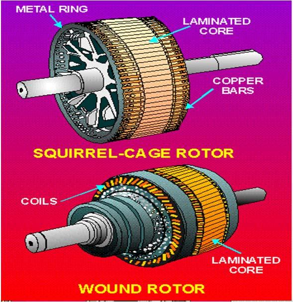
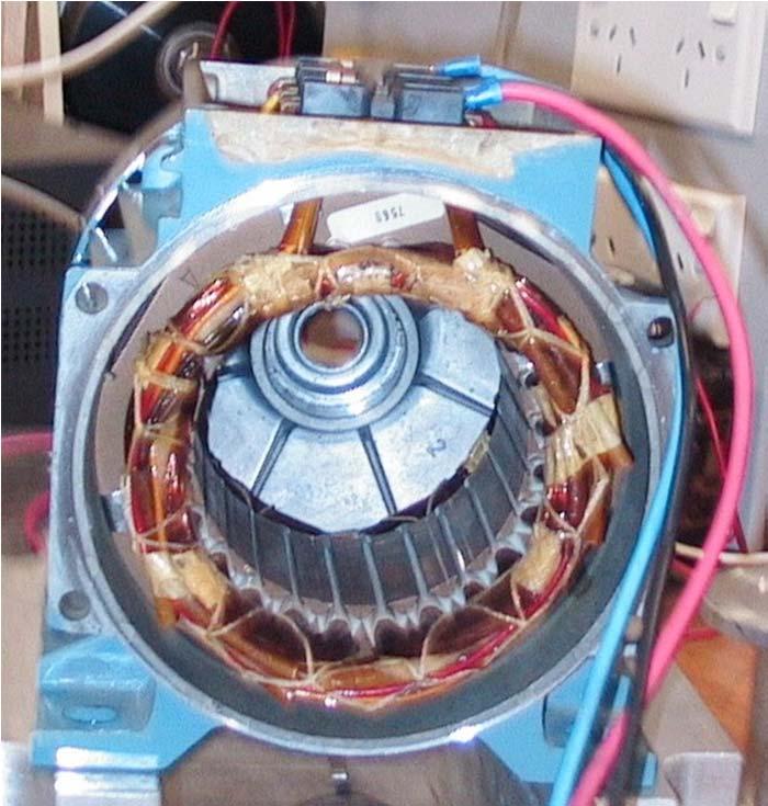
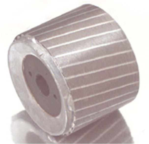
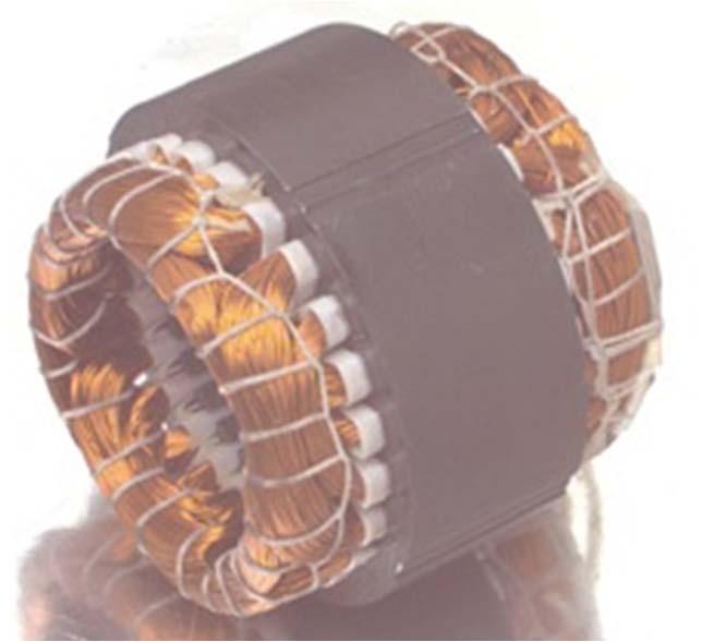
4 Stator and Rotor 3-phae Sinuoidally Ditributed Stator winding Cage rotor Wound rotor 4
5 Working Principle 3-phae balance current of a certain frequency in three-phae tator winding lead to Rotating Magnetic Field Speed of the rotating magnetic field i the ynchronou peed, f f1 1 1 N rev/ec; yn mech rad/ec yn p p p Becaue of thi rotating field, voltage i induced in the rotor winding (or aluminum bar). The conequent 3-phae current flow in the rotor etablihe a rotor field. Interaction between rotor and tator field will produce the neceary torque to rotate the rotor and load with peed n rot. Nrot f /p rev/ec; f rot mech rad/ec p p 5

6 IM working principle continued 6
7 Slip and lip frequency Slip, N Slip frequency, yn rot yn1 rot N yn N yn fr f1 f1 f = 1 when the rotor i at tandtill. = 0 when the motor run at ynchronou peed , normally. The lip frequency, f 1,ithe frequency of the voltage and current induced in the rotor. Rotor induced voltage/phae: E 444N. ˆ f 444N. ˆ f r r r r r 1 Rotor voltage and current are at the lip frequency f 1. 7
8 The Rotor Circuit I X I X I R X E R (a) At lip frequency R a R ; X E a X tan dtill R E (b) (c) At tator frequency I I a A X R R 1 Mechanical load 1 E ae E I I a Rotor circuit Referred to tator E ae E 1 A R 1 8
9 The approximate equivalent circuit I 1 R 1 X 1 I I a A R X V 1 I c R c I m X m E ae E 1 R 1 A Total Rotor Power: Developed Output Power: R 3R E1 R + 1L P = 3I = R Po P I R I P W W 9
10 Developed power and torque Slip Power: l o P P P P 3I R Developed torque = Developed output power/mech peed in rad/ec: Po 3I R1 / Tdev Nm N N rot 3I R 1 / yn N 1 rot 3p I R 3pI R f f f 1 1 Rotor Power Slip Power Syn Speed Slip Speed Nm Nm W 10
11 I 1 R Th X Th A I R X V Th A R 1 V Th X V m 1 R X X 1 1 m jx R jx Z R jx m 1 1 Th Th Th R1 j X1 Xm Note that for X m >> (R 1 and X 1 ); R Th R 1 ; X Th X 1 ;and V Th V 1. 11
12 Rotor current and torque I V Th R Th Th R X X A T 3p Th dev 1 R RTh XTh X V R Nm 1
13 IM torque peed characteritic with variable voltage, rad/ec yn1 V 1 = 1 pu V 1 = 0.7 pu V 1 = 0.5 pu Re-generating 0 V 1 = 0.5 pu V 1 = 0.7 pu V 1 = 1 pu Fwd Motoring Torque, Nm < 0 = 0 = 1 P T Rev Motoring yn1 Plugging >1 = 13
14 Braking of an IM drive with plugging Two way: By adjuting input frequency below haft frequency. By plugging. Note: Operation with high lip caue high power lo; may lead to high rotor temperature a a conequence. 14
15 T max and lip mt for T max For mall lip, T dev 3p V Th 1 R Nm R For maximum torque, R X X mt Th Th Slip for maximum torque, mt R R X X Th Th Maximum torque, T max 3p 1 V Th R R X X Th Th Th Nm Note that T max i independent of R 15
16 IM torque characteritic with R Load T- characteritic 1 R increae T rated T max T dev 16
17 Induction Motor drive 17
18 IM drive with variable upply voltage Variable AC voltage at the main upply frequency can be obtained from tap-changing tranformer, from back-back phae-controlled thyritor converter or from an inverter. V 1 V 1 in max 18
19 T- characteritic with variable voltage V 1 = 0.5 pu 1 V 1 = 0.7 pu V 1 = 1 pu Load T=K 0 Torque, Nm Variable voltage operation at the utility upply (bae) frequency offer very limited peed range. Pump type load are uitable; however, high lip and very loy operation i inevitable with reduced upply voltage. 19
20 Example 1: Voltage control for a fan or compreor load Fan or compreor type load: o m 3 P T K 1 1 K 1 P 1 o P K 1 l P I R P K 1 K R I 1 For maximum P l : =
21 Example : contant load Contant torque type load: P T K 1 o m P P o 1 K l P I R P K I K R Example 1 & how that, the rotor current or rotor power lo increae le lowly with lip (or load) for a fan or compreor type load than for a contant torque type load. 1

22 WRIM drive with variable rotor power AC Main AC Main Wound Rotor IM Slip Ring Variable Reitor Bank Wound Rotor IM Slip Ring 3-f Diode Bridge Rectifier Variable Reitor AC Main V 1 E I d E V d T Wound Rotor IM Slip Ring 3-f Diode Bridge Rectifier Duty Cycle D Variable Reitor
23 T ω characteritic with variable rotor reitance Load T- characteritic 1 R increae T dev T rated T max Figure T characteritic with variable rotor reitance. 3
24 IM drive with variable rotor power (lip power control tatic Scherbiu ytem) I d V 1 1:n V 1 V V d V di 4
25 T - I d characteritic with control of DC link current 3I R 3I R 1 l o P P P 3I R P 3Emax The rectifier output DC voltage, V Equating the AC and DC power, P P V I l d d 3E I max d d P 3E max If the lip power i mall compared to the total rotor (or air-gap) power, i.e., for mall lip, 3E P Tn Tn P I 3Emax 3pE T Id I d n f max o 1 d T KI d 1 1 I d 5
26 Speed control with lip power recovery P Po Pl Pret P 1 P o P l P P ret By neglecting the voltage drop acro tator impedance, E V a 1 The DC output voltage of rectifier, 3 V 3 V n 1 Vdi co co From V d =V di V a co ; n d 3E 3 V a max 1 for > 90 Normally, n a. Why? 6
27 Speed control with lip power recovery Figure d 7
28 A C M A I N S DC R eactor I d T ref SC + _ + _ C C e c FCC 9 Augut 017 8


29 IM drive with 3 phae VSI VVVf inverter V d VAn,1 m 0.354mVd where m i the depth of modulation 9
30 Performance with VVVF upply We aume that the AC upply voltage to the motor i inuoidal, but of arbitrarily variable amplitude (RMS value V 1 ) and frequency f 1. f f 1 o 0 1 for operation from zero to bae peed. i higher than 1 for operation above bae peed. I 1 R 1 X 1 I R X V 1 E 1 I m X m R 1 Figure
31 VVVF (or V/f) drive with contant air gap flux V R I j LI E RI j LI K ˆ f ag 1 For operation near bae peed, the tator voltage drop: can be neglected, compared to V 1. ˆ V V1 Kag f1 K ˆ 1 ag f 1 R I j L I Thu, for operation near bae peed, contant V/f upply implie operation with contant air gap flux. 31
32 T-ω characteritic with contant V/f drive With negligible tator impedance drop, E1 V1 V1 I = R R R j f 1 L +j1l +j1l Vo f1 ˆ f f o 1Kag I R f L R f L 1 1 ˆ 3p R Kag f1 dev 1 R + 1L T = Thu, of f 1. I = 3p 1 f R K ˆ ag 1 R + f L Nm and T dev value remain the ame for a given f 1,regardle 3
33 IM drive with contant V/f ratio I T dev f 1 Slip freq, f 1 Slip freq, f 1 n o n 1 f o n o n 1 f o f 1 f 1 n n 3 f n f 4 n 3 f f 3 I 33
34 Starting with maximum torque, V/f drive For maximum developed power and torque in the rotor circuit R X When T max i developed, 1 f1 R f f f f 1 o X for 1 1 X f f f Note: maximum torque occur at the ame lip frequency for all f 1. For maximum torque to occur at zero peed, f fr o R 1 X L From and 5..7, T max ˆ ag 3p K 4 X f o Nm 34
35 IM drive with contant V/f ratio Rated V 1 Kˆ gap V 1 f o f 1 35
36 Contant max torque and power characteritic Speed, Rad/ec Rated V 1 & f o T dev Nm T max Figure T- characteritic under VVVF drive with f 1 below and above f o. 36
37 T characteritic with VSI V/f drive, rad/ec Bae peed with rated V 1 and bae f 1 Q Q 1 Sequence: a-b-c T rated T max T, Nm Sequence: a-c-b Q 3 Q 4 37
38 V/f drive at low peed V R I j L I E R I j L I K ˆ f ag 1 R I j L I At low peed, the tator impedance drop: may not remain negligible compared to V 1 or E 1. It implie reduction of the air-gap flux ˆ ag,, and conequent reduction of T dev 3p R K ˆ f ag 1 dev 1 R + 1L T = 38
39 V/f drive at low peed Bae Speed Speed, Rad/ec 1 increae with negligible tator impedance with tator impedance T dev Nm Figure Drooping T- characteritic at low peed with VVVF drive 39
40 V/f drive with low frequency voltage boot Rated V 1 low-frequency voltage boot V bo f 1 f o Figure Voltage boot of VVVF drive at low peed The zero-frequency boot i V R I bo 1 1rated 40
41 VSI V/f drive controller open loop Speed reference 1 1 T f V 1 Reference f 1 Reference Open loop V/f controller 41
42 Speed control with an inner lip loop E V K ˆ f I = R R R f L 1 1 ag 1 +j1l +j1l 1 V 1 * l + + f 1 Fig Cloed loop peed controller with inner lip control 4
43 CSI drive tructure for IM Vdc A B C Motor * i a P W M * i b P W M * i c P W M 43
44 IM drive with variable I-f upply I 1 A I j X I m I 1 jx m E 1 R A Figure Per-phae equivalent circuit with current ource input 44
45 IM drive with variable I-f upply T dev 3pI R f 1 Torque i inverely proportional to lip frequency 45
46 IM drive with variable I-f upply Maximum rotor power and hence developed torque occur when R X m X 1 f1 R f f f f 1 o X m X When T max i developed mt X R m X fr o 1 1 Xm X f f f Normally, X m >> X. S mt for CSI drive i much maller than for VSI. For tarting from tandtill with T max For maximum torque to occur at tart f X R m X fr o R 1 Xm X Lm L 46
47 IM drive with variable I-f upply contd. T dev 3pI R f f 1 For a given I 1, the rotor current I i given by (uing current diviion) I j X I m 1 R j Xm X Uing the lip condition for maximum torque, mt X R m X T max XmI1 m o 3p 4 X X f Nm 47
48 I-f drive with contant air-gap flux I I m 1 R R j X m j X X I R f1l I m 1 R f1 Lm L 48
49 I 1 for contant air gap flux operation I 1 Q Q 1 No load I 1 -f 1 0 +f 1 Q 3 Q 4 I 1 in revere equence 49
50 I 1 at no-load E1 X ˆ mim Kag f E V 1 1rated 1 K ˆ ag f f E X I 1 m m 1rated m m ag f1 f1 fo fo K ˆ I m I 1,no load V 1rated X m V X I 1 o 50
51 Speed-control ytem block diagram ref + + l f 1 I 1 I-Ref Gen I N V M + Figure Variable current, variable frequency inverter drive cheme. 51
52 CSI I/f drive for large IM machine Rectifier L I d Inverter T1 C T3 C T5 AC Main C C C T4 T6 C T * I d FCCR e c1 e c e c3 FCCI T1 T6 M T 5
53 Quai-quare phae current waveform i a T 1 T 1 +I d T 4 T 4 -I d T 1 i b T 6 T 3 T 3 T 6 T 6 i c T T 5 T T 5 Figure Motor current waveform and thyritor witching tate for a current ource drive. 53
Section Induction motor drives
 Section 5.1 - nduction motor drive Electric Drive Sytem 5.1.1. ntroduction he AC induction motor i by far the mot widely ued motor in the indutry. raditionally, it ha been ued in contant and lowly variable-peed
BASIC INDUCTION MOTOR CONCEPTS
 INDUCTION MOTOS An induction motor ha the ame phyical tator a a ynchronou machine, with a different rotor contruction. There are two different type of induction motor rotor which can be placed inide the
Basic parts of an AC motor : rotor, stator, The stator and the rotor are electrical
 INDUCTION MOTO 1 CONSTUCTION Baic part of an AC motor : rotor, tator, encloure The tator and the rotor are electrical circuit that perform a electromagnet. CONSTUCTION (tator) The tator - tationary part
No-load And Blocked Rotor Test On An Induction Machine
 No-load And Blocked Rotor Tet On An Induction Machine Aim To etimate magnetization and leakage impedance parameter of induction machine uing no-load and blocked rotor tet Theory An induction machine in
ECE 325 Electric Energy System Components 6- Three-Phase Induction Motors. Instructor: Kai Sun Fall 2015
 ECE 35 Electric Energy Sytem Component 6- Three-Phae Induction Motor Intructor: Kai Sun Fall 015 1 Content (Material are from Chapter 13-15) Component and baic principle Selection and application Equivalent
Synchronous Machines - Structure
 Synchronou Machine - Structure Synchronou Machine - Structure rotate at contant peed. primary energy converion device of the word electric power ytem. both generator and motor operation can draw either
Overview: Induction Motors. Review Questions. Why the Rotor Moves: Motor Speed
 Overview: nduction Motor Motor operation & Slip Speed-torque relationhip Equivalent circuit model Tranformer Motor efficiency Starting induction motor Smith College, EGR 35 ovember 5, 04 Review Quetion
Overview Electrical Machines and Drives
 Overview Electrical Machine and Drive 7-9 1: Introduction, Maxwell equation, magnetic circuit 11-9 1.-3: Magnetic circuit, Princile 14-9 3-4.: Princile, DC machine 18-9 4.3-4.7: DC machine and drive 1-9
15 Problem 1. 3 a Draw the equivalent circuit diagram of the synchronous machine. 2 b What is the expected synchronous speed of the machine?
 Exam Electrical Machine and Drive (ET4117) 6 November 009 from 9.00 to 1.00. Thi exam conit of 4 problem on 4 page. Page 5 can be ued to anwer problem quetion b. The number before a quetion indicate how
Performance Improvement of Direct Torque Controlled Interior Permanent Magnet Synchronous Motor Drive by Considering Magnetic Saturation
 Performance Improvement of Direct Torque Controlled Interior Permanent Magnet Synchronou Motor Drive by Conidering Magnetic Saturation Behrooz Majidi * Jafar Milimonfared * Kaveh Malekian * *Amirkabir
ISSN: [Basnet* et al., 6(3): March, 2017] Impact Factor: 4.116
![ISSN: [Basnet* et al., 6(3): March, 2017] Impact Factor: 4.116](/thumbs/95/123902996.jpg "ISSN: [Basnet* et al., 6(3): March, 2017] Impact Factor: 4.116") IJESR INERNAIONAL JOURNAL OF ENGINEERING SCIENCES & RESEARCH ECHNOLOGY DIREC ORQUE CONROLLED INDUCION MOOR DRIVE FOR ORQUE RIPPLE REDUCION Bigyan Banet Department of Electrical Engineering, ribhuvan Univerity,
IJESR INERNAIONAL JOURNAL OF ENGINEERING SCIENCES & RESEARCH ECHNOLOGY DIREC ORQUE CONROLLED INDUCION MOOR DRIVE FOR ORQUE RIPPLE REDUCION Bigyan Banet Department of Electrical Engineering, ribhuvan Univerity,
Lecture Set 8 Induction Machines
 Lecture Set 8 Induction Machine S.D. Sudhoff Spring 2018 Reading Chapter 6, Electromechanical Motion Device, Section 6.1-6.9, 6.12 2 Sample Application Low Power: Shaded pole machine (mall fan) Permanent
60 p. 2. A 200hp 600V, 60 Hz 3-phase induction motor has start code F. What line current should be expected at starting? 4 marks.
 EE 004 Final Solution : Thi wa a hr exam. A 60 Hz 4 pole -phae induction motor rotate at 740rpm. a) What i the lip? mark b) What i the peed o rotation o the rotor magnetic ield (in rpm)? mark The motor
FUNDAMENTALS OF POWER SYSTEMS
 1 FUNDAMENTALS OF POWER SYSTEMS 1 Chapter FUNDAMENTALS OF POWER SYSTEMS INTRODUCTION The three baic element of electrical engineering are reitor, inductor and capacitor. The reitor conume ohmic or diipative
DIRECT TORQUE CONTROL OF THREE PHASE INDUCTION MOTOR USING FUZZY LOGIC SPEED CONTROLLER FOR STEADY/DYNAMIC STATE RESPONSE
 DIRECT TORQUE CONTROL OF THREE PHASE INDUCTION MOTOR USING FUZZY LOGIC SPEED CONTROLLER FOR STEADY/DYNAMIC STATE RESPONSE 1 C. MOHAN RAJ, 2 K.KEERTHIVASAN, 3 RANJITH KUMAR DINAKARAN, 4 N.PUSHPALATHA 1
Three Phase Induction Motors
 Chapter (8) hree Phae Induction Motor Introduction he three-phae induction otor are the ot widely ued electric otor in indutry. hey run at eentially contant peed fro no-load to full-load. However, the
The Influence of the Load Condition upon the Radial Distribution of Electromagnetic Vibration and Noise in a Three-Phase Squirrel-Cage Induction Motor
 The Influence of the Load Condition upon the Radial Ditribution of Electromagnetic Vibration and Noie in a Three-Phae Squirrel-Cage Induction Motor Yuta Sato 1, Iao Hirotuka 1, Kazuo Tuboi 1, Maanori Nakamura
What lies between Δx E, which represents the steam valve, and ΔP M, which is the mechanical power into the synchronous machine?
 A 2.0 Introduction In the lat et of note, we developed a model of the peed governing mechanim, which i given below: xˆ K ( Pˆ ˆ) E () In thee note, we want to extend thi model o that it relate the actual
Induction Motors. The single-phase induction motor is the most frequently used motor in the world
 Induction Motor The single-phase induction motor is the most frequently used motor in the world Most appliances, such as washing machines and refrigerators, use a single-phase induction machine Highly
Comparison of Hardware Tests with SIMULINK Models of UW Microgrid
 Comparion of Hardware Tet with SIMULINK Model of UW Microgrid Introduction Thi report include a detailed dicuion of the microource available on the Univerity- of- Wiconin microgrid. Thi include detail
Analysis the Transient Process of Wind Power Resources when there are Voltage Sags in Distribution Grid
 Analyi the Tranient Proce of Wind Power Reource when there are Voltage Sag in Ditribution Grid Do Nhu Y 1,* 1 Hanoi Univerity of ining and Geology, Deartment of Electrification, Electromechanic Faculty,
Question 1 Equivalent Circuits
 MAE 40 inear ircuit Fall 2007 Final Intruction ) Thi exam i open book You may ue whatever written material you chooe, including your cla note and textbook You may ue a hand calculator with no communication
Lecture 4. Chapter 11 Nise. Controller Design via Frequency Response. G. Hovland 2004
 METR4200 Advanced Control Lecture 4 Chapter Nie Controller Deign via Frequency Repone G. Hovland 2004 Deign Goal Tranient repone via imple gain adjutment Cacade compenator to improve teady-tate error Cacade
Delhi Noida Bhopal Hyderabad Jaipur Lucknow Indore Pune Bhubaneswar Kolkata Patna Web: Ph:
 Serial : Ch1_EE_C_Power Electronic_6818 Delhi Noida Bhopal Hyderabad Jaipur ucknow Indore Pune Bhubanewar Kolkata Patna Web: E-mail: info@madeeay.in Ph: 11-451461 CASS ES 18-19 EECRICA ENGINEERING Subject
Open Access Study of Direct Torque Control Scheme for Induction Motor Based on Torque Angle Closed-Loop Control. Xuande Ji *, Daqing He and Yunwang Ge
 Send Order for Reprint to reprint@benthamcience.ae 6 The Open Electrical & Electronic Engineering Journal, 25, 9, 669 Open Acce Study of Direct Torque Control Scheme for Induction Motor Baed on Torque
Chapter 4. Synchronous Generators. Basic Topology
 Basic Topology Chapter 4 ynchronous Generators In stator, a three-phase winding similar to the one described in chapter 4. ince the main voltage is induced in this winding, it is also called armature winding.
Representation of a Group of Three-phase Induction Motors Using Per Unit Aggregation Model A.Kunakorn and T.Banyatnopparat
 epreentation of a Group of Three-phae Induction Motor Uing Per Unit Aggregation Model A.Kunakorn and T.Banyatnopparat Abtract--Thi paper preent a per unit gregation model for repreenting a group of three-phae
Sensorless speed control including zero speed of non salient PM synchronous drives
 BULLETIN OF THE POLISH ACADEMY OF SCIENCES TECHNICAL SCIENCES Vol. 54, No. 3, 2006 Senorle peed control including zero peed of non alient PM ynchronou drive H. RASMUSSEN Aalborg Univerity, Fredrik Bajer
Lecture 12 - Non-isolated DC-DC Buck Converter
 ecture 12 - Non-iolated DC-DC Buck Converter Step-Down or Buck converter deliver DC power from a higher voltage DC level ( d ) to a lower load voltage o. d o ene ref + o v c Controller Figure 12.1 The
SERIES COMPENSATION: VOLTAGE COMPENSATION USING DVR (Lectures 41-48)
") Chapter 5 SERIES COMPENSATION: VOLTAGE COMPENSATION USING DVR (Lecture 41-48) 5.1 Introduction Power ytem hould enure good quality of electric power upply, which mean voltage and current waveform hould
Chapter 5 SERIES COMPENSATION: VOLTAGE COMPENSATION USING DVR (Lecture 41-48) 5.1 Introduction Power ytem hould enure good quality of electric power upply, which mean voltage and current waveform hould
18 Problem 1. 7 d Sketch a cross section of a switched reluctance machine and explain the principle of operation.
 Exam Electrical Machine and Drive (ET4117) 9 November 01 from 14.00 to 17.00. Thi exam conit of 3 roblem on 3 age. Page 5 can be ued to anwer roblem 4 quetion a. The number before a quetion indicate how
R. W. Erickson. Department of Electrical, Computer, and Energy Engineering University of Colorado, Boulder
 R. W. Erickon Department of Electrical, Computer, and Energy Engineering Univerity of Colorado, Boulder ZOH: Sampled Data Sytem Example v T Sampler v* H Zero-order hold H v o e = 1 T 1 v *( ) = v( jkω
Liquid cooling
 SKiiPPACK no. 3 4 [ 1- exp (-t/ τ )] + [( P + P )/P ] R [ 1- exp (-t/ τ )] Z tha tot3 = R ν ν tot1 tot tot3 thaa-3 aa 3 ν= 1 3.3.6. Liquid cooling The following table contain the characteritic R ν and
Estimation of Temperature Rise in Stator Winding and Rotor Magnet of PMSM Based on EKF
 2010 3rd International Conference on Computer and Electrical Engineering (ICCEE 2010) IPCSIT vol. 53 (2012) (2012) IACSIT Pre, Singapore DOI: 10.7763/IPCSIT.2012.V53.No.2.37 Etimation of Temperature Rie
EE C128 / ME C134 Problem Set 1 Solution (Fall 2010) Wenjie Chen and Jansen Sheng, UC Berkeley
 Wenjie Chen and Jansen Sheng, UC Berkeley") EE C28 / ME C34 Problem Set Solution (Fall 200) Wenjie Chen and Janen Sheng, UC Berkeley. (0 pt) BIBO tability The ytem h(t) = co(t)u(t) i not BIBO table. What i the region of convergence for H()? A bounded
EE C28 / ME C34 Problem Set Solution (Fall 200) Wenjie Chen and Janen Sheng, UC Berkeley. (0 pt) BIBO tability The ytem h(t) = co(t)u(t) i not BIBO table. What i the region of convergence for H()? A bounded
Per Unit Analysis. Single-Phase systems
 Per Unit Analyi The per unit method of power ytem analyi eliminate the need for converion of voltae, current and impedance acro every tranformer in the circuit. n addition, the need to tranform from 3-
376 CHAPTER 6. THE FREQUENCY-RESPONSE DESIGN METHOD. D(s) = we get the compensated system with :
 = we get the compensated system with :") 376 CHAPTER 6. THE FREQUENCY-RESPONSE DESIGN METHOD Therefore by applying the lead compenator with ome gain adjutment : D() =.12 4.5 +1 9 +1 we get the compenated ytem with : PM =65, ω c = 22 rad/ec, o
376 CHAPTER 6. THE FREQUENCY-RESPONSE DESIGN METHOD Therefore by applying the lead compenator with ome gain adjutment : D() =.12 4.5 +1 9 +1 we get the compenated ytem with : PM =65, ω c = 22 rad/ec, o
Chapter 6. Induction Motors. Copyright The McGraw-Hill Companies, Inc. Permission required for reproduction or display.
 Chapter 6 Induction Motors 1 The Development of Induced Torque in an Induction Motor Figure 6-6 The development of induced torque in an induction motor. (a) The rotating stator field B S induces a voltage
The Measurement of DC Voltage Signal Using the UTI
 he Meaurement of DC Voltage Signal Uing the. INRODUCION can er an interface for many paive ening element, uch a, capacitor, reitor, reitive bridge and reitive potentiometer. By uing ome eternal component,
Sensorless PM Brushless Drives
 IEEE UK Chapter Seminar 15 December 3 Senorle PM Bruhle Drive Prof. D. Howe and Prof. Z. Q. Zhu The Univerity of Sheffield Electrical Machine & Drive Reearch Group Outline Review of enorle technique Zero-croing
RECURSIVE LEAST SQUARES HARMONIC IDENTIFICATION IN ACTIVE POWER FILTERS. A. El Zawawi, K. H. Youssef, and O. A. Sebakhy
 RECURSIVE LEAST SQUARES HARMONIC IDENTIFICATION IN ACTIVE POWER FILTERS A. El Zawawi, K. H. Youef, and O. A. Sebakhy Department of Electrical Engineering, Alexandria Univerity, Alexandria 21544, Egypt.P.O.
Massachusetts Institute of Technology Department of Electrical Engineering and Computer Science Electric Machines
 Massachusetts Institute of Technology Department of Electrical Engineering and Computer Science 6.685 Electric Machines Problem Set 10 Issued November 11, 2013 Due November 20, 2013 Problem 1: Permanent
Direct Torque Control of Saturated Induction Machine with and without speed sensor
 Journal of Advanced Reearch in Science and Technology ISSN: 2352-9989 Direct Torque Control of Saturated Induction Machine with and without peed enor Tahar Djellouli,2, Samir Moulahoum, Med Seghir Boucherit
Tutorial 5 Drive dynamics & control
 UNIVERSITY OF NEW SOUTH WALES Electic Dive Sytem School o Electical Engineeing & Telecommunication ELEC463 Electic Dive Sytem Tutoial 5 Dive dynamic & contol. The ollowing paamete ae known o two high peomance
A Novel Start-Up Scheme of Stator Flux Oriented Vector Controlled Induction Motor Drive Without Torque Jerk
 A Novel Start-Up Scheme of Stator Flux Oriented Vector Controlled nduction Motor Drive Without Torque Jerk Tae-Won Chun, Meong-Kyu Choi * Bimal K. Boe Dept. of Electrical Engineering, Univerity Mu-Gu-Dong,
ECE Linear Circuit Analysis II
 ECE 202 - Linear Circuit Analyi II Final Exam Solution December 9, 2008 Solution Breaking F into partial fraction, F 2 9 9 + + 35 9 ft δt + [ + 35e 9t ]ut A 9 Hence 3 i the correct anwer. Solution 2 ft
MAE140 Linear Circuits Fall 2012 Final, December 13th
 MAE40 Linear Circuit Fall 202 Final, December 3th Intruction. Thi exam i open book. You may ue whatever written material you chooe, including your cla note and textbook. You may ue a hand calculator with
MATHEMATICAL MODELING OF INDUCTION MOTORS
 37 CHAPTER 3 MATHEMATICAL MODELING OF INDUCTION MOTORS To tart with, a well-known technique called the SVPWM technique i dicued a thi form the bai of the mathematical modeling of IM. Furthermore, the d
Experimental Direct Torque Control Induction Motor Drive with Modified Flux Estimation and Speed control Algorithm.
 Experimental Direct Torque Control Induction Motor Drive with Modified Flux Etimation and Speed control Algorithm. Bhoopendra ingh, Shailendra Jain 2, Sanjeet Dwivedi 3 (RGTU, Bhopal), 2 (MANIT Bhopal),
Simulation and Analysis of Linear Permanent Magnet Vernier Motors for Direct Drive Systems
 Available online at www.ijpe-online.com vol. 3, no. 8, December 07, pp. 304-3 DOI: 0.3940/ijpe.7.08.p.3043 Simulation and Analyi of Linear Permanent Magnet Vernier Motor for Direct Drive Sytem Mingjie
Lecture 23 Date:
 Lecture 3 Date: 4.4.16 Plane Wave in Free Space and Good Conductor Power and Poynting Vector Wave Propagation in Loy Dielectric Wave propagating in z-direction and having only x-component i given by: E
3 d Calculate the product of the motor constant and the pole flux KΦ in this operating point. 2 e Calculate the torque.
 Exam Electrical Machines and Drives (ET4117) 11 November 011 from 14.00 to 17.00. This exam consists of 5 problems on 4 pages. Page 5 can be used to answer problem 4 question b. The number before a question
Electric Machines I Three Phase Induction Motor. Dr. Firas Obeidat
 Electric Machines I Three Phase Induction Motor Dr. Firas Obeidat 1 Table of contents 1 General Principles 2 Construction 3 Production of Rotating Field 4 Why Does the Rotor Rotate 5 The Slip and Rotor
Tuning of High-Power Antenna Resonances by Appropriately Reactive Sources
 Senor and Simulation Note Note 50 Augut 005 Tuning of High-Power Antenna Reonance by Appropriately Reactive Source Carl E. Baum Univerity of New Mexico Department of Electrical and Computer Engineering
A Novel Direct Torque Control Scheme for Induction Machines With Space Vector Modulation
 24 35th Annual IEEE Power Electronic Specialit Conference Aachen, Germany, 24 A Novel Direct Torque Control Scheme for Induction Machine With Space Vector Modulation Joé Rodríguez, Jorge Pontt, Céar Silva,
online learning Unit Workbook 4 RLC Transients
 online learning Pearon BTC Higher National in lectrical and lectronic ngineering (QCF) Unit 5: lectrical & lectronic Principle Unit Workbook 4 in a erie of 4 for thi unit Learning Outcome: RLC Tranient
Dynamic Simulation of NEK Reactor Coolant Pump with a Best Estimate Full Scale Model in APROS
 Dynamic Simulation of NEK Reactor Coolant Pump with a Bet Etimate Full Scale Model in APROS ABSTRACT Dejan Slovenc ZEL-EN d.o.o. Hočevarjev trg 1, 870, Krško, Slovenia dejan.lovenc@zel-en.i Ivica Bašić
Sensorless PMSM Field Oriented Control Solution Based on TI Cortex-M3
 Senorle PMSM Field Oriented Control Solution Baed on TI Cortex-M3 AEDS Team Technical Service Arrow Steven Wang Agenda Permanent Magnet Synchronou Motor Field Oriented Control Realization Senorle Control
ECEN620: Network Theory Broadband Circuit Design Fall 2018
 ECEN60: Network Theory Broadband Circuit Deign Fall 08 Lecture 6: Loop Filter Circuit Sam Palermo Analog & Mixed-Signal Center Texa A&M Univerity Announcement HW i due Oct Require tranitor-level deign
Digital Control System
 Digital Control Sytem - A D D A Micro ADC DAC Proceor Correction Element Proce Clock Meaurement A: Analog D: Digital Continuou Controller and Digital Control Rt - c Plant yt Continuou Controller Digital
EE/ME/AE324: Dynamical Systems. Chapter 8: Transfer Function Analysis
 EE/ME/AE34: Dynamical Sytem Chapter 8: Tranfer Function Analyi The Sytem Tranfer Function Conider the ytem decribed by the nth-order I/O eqn.: ( n) ( n 1) ( m) y + a y + + a y = b u + + bu n 1 0 m 0 Taking
Direct Torque Control using Matrix Converters
 Chapter 5 Direct Torque Control uing Matrix Converter The Direct Torque Control (DTC) i a high-dynamic and high performance control technique for induction motor drive which ha been developed in the lat
Reference:W:\Lib\MathCAD\Default\defaults.mcd
 4/9/9 Page of 5 Reference:W:\Lib\MathCAD\Default\default.mcd. Objective a. Motivation. Finite circuit peed, e.g. amplifier - effect on ignal. E.g. how "fat" an amp do we need for audio? For video? For
Feedback Control Systems (FCS)
") Feedback Control Sytem (FCS) Lecture19-20 Routh-Herwitz Stability Criterion Dr. Imtiaz Huain email: imtiaz.huain@faculty.muet.edu.pk URL :http://imtiazhuainkalwar.weebly.com/ Stability of Higher Order
Feedback Control Sytem (FCS) Lecture19-20 Routh-Herwitz Stability Criterion Dr. Imtiaz Huain email: imtiaz.huain@faculty.muet.edu.pk URL :http://imtiazhuainkalwar.weebly.com/ Stability of Higher Order
ME 375 FINAL EXAM Wednesday, May 6, 2009
 ME 375 FINAL EXAM Wedneday, May 6, 9 Diviion Meckl :3 / Adam :3 (circle one) Name_ Intruction () Thi i a cloed book examination, but you are allowed three ingle-ided 8.5 crib heet. A calculator i NOT allowed.
Dynamic Simulation of a Three-Phase Induction Motor Using Matlab Simulink
 Dynamic Simulation of a ThreePhae Induction Motor Uing Matlab Simulink Adel Aktaibi & Daw Ghanim, graduate tudent member, IEEE, M. A. Rahman, life fellow, IEEE, Faculty of Engineering and Applied Science,
Chapter 9: Controller design. Controller design. Controller design
 Chapter 9. Controller Deign 9.. Introduction 9.2. Eect o negative eedback on the network traner unction 9.2.. Feedback reduce the traner unction rom diturbance to the output 9.2.2. Feedback caue the traner
Massachusetts Institute of Technology Dynamics and Control II
 I E Maachuett Intitute of Technology Department of Mechanical Engineering 2.004 Dynamic and Control II Laboratory Seion 5: Elimination of Steady-State Error Uing Integral Control Action 1 Laboratory Objective:
J. Electrical Systems 6-3 (2010): A COMPARATIVE STUDY ON PERFORMANCE IMPROVEMENT OF A PHOTOVOLTAIC PUMPING SYSTEM
: A COMPARATIVE STUDY ON PERFORMANCE IMPROVEMENT OF A PHOTOVOLTAIC PUMPING SYSTEM") A. Betka A.Moui J. Electrical Sytem 6- (00): 6-5 A COMPARATIE STUDY ON PERFORMANCE IMPROEMENT OF A PHOTOOLTAIC PUMPING SYSTEM Thi paper ugget how an optimal operation of a photovoltaic pumping ytem baed
A. Betka A.Moui J. Electrical Sytem 6- (00): 6-5 A COMPARATIE STUDY ON PERFORMANCE IMPROEMENT OF A PHOTOOLTAIC PUMPING SYSTEM Thi paper ugget how an optimal operation of a photovoltaic pumping ytem baed
Study on Short Circuit Current Calculation of Power System with UHVDC and New Energy Source
 Energy and Power Engineering, 2017, 9, 625-634 http://www.cirp.org/journal/epe ISSN Online: 1947-3818 ISSN Print: 1949-243X Study on Short Circuit Current Calculation of Power Sytem with UHVDC and New
: 2 : EE-Conventional Test-10 (Solutions)
") .(a) Sol: The hunt field current At no load, armature current ounter e.m.f, E a I f I a. A 5 A 9.4 : : EE-onventional Tet- (Solution) otational loe = E al I a 9.4 58. watt At full load, armature current
.(a) Sol: The hunt field current At no load, armature current ounter e.m.f, E a I f I a. A 5 A 9.4 : : EE-onventional Tet- (Solution) otational loe = E al I a 9.4 58. watt At full load, armature current
A NEW EQUIVALENT CIRCUIT OF THE THREE-PHASE INDUCTION MOTOR (CASE STUDIES:CURRENT AND POWER FACTOR OF THE MOTOR)
") VO. 1, NO. 3, DECEBER 017 SSN 1819-6608 ARPN Journal of Engineering and Applied Science 006-017 Aian Reearch Publihing Network (ARPN. All right reerved. www.arpnjournal.com A NEW EQUVAENT CRCUT OF THE
VO. 1, NO. 3, DECEBER 017 SSN 1819-6608 ARPN Journal of Engineering and Applied Science 006-017 Aian Reearch Publihing Network (ARPN. All right reerved. www.arpnjournal.com A NEW EQUVAENT CRCUT OF THE
Implementation of Field Oriented Speed Sensorless Control of Induction Motor Drive
 International Journal on Electrical Engineering and Informatic - Volume 8, Number 4, December 216 Implementation of Field Oriented Speed Senorle Control of Induction Motor Drive R. Gunabalan 1 and V. Subbiah
Thermal Resistance Measurements and Thermal Transient Analysis of Power Chip Slug-Up and Slug-Down Mounted on HDI Substrate
 Intl Journal of Microcircuit and Electronic Packaging Thermal Reitance Meaurement and Thermal Tranient Analyi of Power Chip Slug-Up and Slug-Down Mounted on HDI Subtrate Claudio Sartori Magneti Marelli
Introduction to Synchronous. Machines. Kevin Gaughan
 Introduction to Synchronous Machines Kevin Gaughan The Synchronous Machine An AC machine (generator or motor) with a stator winding (usually 3 phase) generating a rotating magnetic field and a rotor carrying
Permanent Magnet Synchronous Motors (PMSM). Parameters influence on the synchronization process of a PMSM
. Parameters influence on the synchronization process of a PMSM") Permanent Magnet ynchronous Motors (PMM). Parameters influence on the synchronization process of a PMM J. ais, M. P. Donsión Department of Electromechanics and Power Electronics Faculty of electrical engineering
Permanent Magnet ynchronous Motors (PMM). Parameters influence on the synchronization process of a PMM J. ais, M. P. Donsión Department of Electromechanics and Power Electronics Faculty of electrical engineering
VARIABLE speed drive systems are essential in
 1 Senorle Field Orientation Control of Induction Motor Uing Reduced Order Oberver R. Mehram, S. Bahadure, S. Matani, G. Datkhile, T. Kumar, S. Wagh Electrical Engineering Department Veermata Jijabai Technological
III.9. THE HYSTERESIS CYCLE OF FERROELECTRIC SUBSTANCES
 III.9. THE HYSTERESIS CYCLE OF FERROELECTRIC SBSTANCES. Work purpoe The analyi of the behaviour of a ferroelectric ubtance placed in an eternal electric field; the dependence of the electrical polariation
Loss Minimization in an Induction Motor Driven by a Voltage-Source-Inverter
 Aian J. Energy Environ., Vol. 3 Iue 1-, (00), pp. 53-78 Lo Minimization in an Induction Motor Driven by a Voltage-Source-Inverter S. Sujitjorn and K-L. Areerak School of Electrical Engineering, Suranaree
INDUCTION MOTOR MODEL AND PARAMETERS
 APPENDIX C INDUCTION MOTOR MODEL AND PARAMETERS C.1 Dynamic Model of the Induction Motor in Stationary Reference Frame A three phase induction machine can be represented by an equivalent two phase machine
Solution of Tutorial 3 Synchronous Motor Drives
 chool of lectrical ngineering & Telecommunications, UNW lectric Drive ystems olution of Tutorial 3 ynchronous Motor Drives Question. R 0, XO 72at the base speed corresponding to 50 Hz operation. 6600 fo
Introduction to Laplace Transform Techniques in Circuit Analysis
 Unit 6 Introduction to Laplace Tranform Technique in Circuit Analyi In thi unit we conider the application of Laplace Tranform to circuit analyi. A relevant dicuion of the one-ided Laplace tranform i found
II. DYNAMIC MACHINE MODEL OF AN INDUCTION MOTOR
 Direct Torque Control Senorle nduction Motor Drive Uing Space Vector Modulation Manoj Bhaurao Deokate, D. N. Katole 2, R.V.Humane Reearch Scholar, Aitant Profeor, Department of Electrical Engineering,
An Introduction to Electrical Machines. P. Di Barba, University of Pavia, Italy
 An Introduction to Electrical Machines P. Di Barba, University of Pavia, Italy Academic year 0-0 Contents Transformer. An overview of the device. Principle of operation of a single-phase transformer 3.
د شوقي حامد عرفه ابراهيم
 2015 /1/19 اإلجابة النموذجية لمادة نظم التشغيل الكهربية ك 563 د شوقي حامد عرفه ابراهيم يوم االثنين الموافق Benha University Benha Faculty of Engineering Subject: Electrical drives (E563) Time: 3hours Fifth
Chapter 5 Three phase induction machine (1) Shengnan Li
 Shengnan Li") Chapter 5 Three phase induction machine (1) Shengnan Li Main content Structure of three phase induction motor Operating principle of three phase induction motor Rotating magnetic field Graphical representation
Chapter 5 Three phase induction machine (1) Shengnan Li Main content Structure of three phase induction motor Operating principle of three phase induction motor Rotating magnetic field Graphical representation
POWER QUALITY AND RELIABILITY SUPPLY IMPROVEMENT USING A POWER CONDITIONING SYSTEM WITH ENERGY STORAGE CAPABILITY
 POWER QUALITY AND RELIABILITY UPPLY IMPROVEMENT UING A POWER CONDITIONING YTEM WITH ENERGY TORAGAPABILITY Domenico Caadei, Gabriele Grandi, Claudio Roi Department of Electrical Engineering Univerity of
CHAPTER 14 SIGNAL GENERATORS AND WAVEFORM-SHAPING CIRCUITS
 CHAPTE 4 SIGNA GENEATS AN WAEFM-SHAPING CICUITS Chapter utline 4. Baic Principle o Sinuoidal cillator 4. p Amp-C cillator 4. C and Crytal cillator 4.4 Bitable Multiibrator 4.5 Generation o Square and Triangular
University of Jordan Faculty of Engineering & Technology Electric Power Engineering Department
 University of Jordan Faculty of Engineering & Technology Electric Power Engineering Department EE471: Electrical Machines-II Tutorial # 2: 3-ph Induction Motor/Generator Question #1 A 100 hp, 60-Hz, three-phase
ECE 3510 Root Locus Design Examples. PI To eliminate steady-state error (for constant inputs) & perfect rejection of constant disturbances
 & perfect rejection of constant disturbances") ECE 350 Root Locu Deign Example Recall the imple crude ervo from lab G( ) 0 6.64 53.78 σ = = 3 23.473 PI To eliminate teady-tate error (for contant input) & perfect reection of contant diturbance Note:
ECE 350 Root Locu Deign Example Recall the imple crude ervo from lab G( ) 0 6.64 53.78 σ = = 3 23.473 PI To eliminate teady-tate error (for contant input) & perfect reection of contant diturbance Note:
Equivalent Circuits with Multiple Damper Windings (e.g. Round rotor Machines)
") Equivalent Circuits with Multiple Damper Windings (e.g. Round rotor Machines) d axis: L fd L F - M R fd F L 1d L D - M R 1d D R fd R F e fd e F R 1d R D Subscript Notations: ( ) fd ~ field winding quantities
Equivalent Circuits with Multiple Damper Windings (e.g. Round rotor Machines) d axis: L fd L F - M R fd F L 1d L D - M R 1d D R fd R F e fd e F R 1d R D Subscript Notations: ( ) fd ~ field winding quantities
Lecture 8. PID control. Industrial process control ( today) PID control. Insights about PID actions
 PID control. Insights about PID actions") Lecture 8. PID control. The role of P, I, and D action 2. PID tuning Indutrial proce control (92... today) Feedback control i ued to improve the proce performance: tatic performance: for contant reference,
Lecture 8. PID control. The role of P, I, and D action 2. PID tuning Indutrial proce control (92... today) Feedback control i ued to improve the proce performance: tatic performance: for contant reference,
JRE SCHOOL OF Engineering
 JRE SCHOOL OF Engineering Class Test-1 Examinations September 2014 Subject Name Electromechanical Energy Conversion-II Subject Code EEE -501 Roll No. of Student Max Marks 30 Marks Max Duration 1 hour Date
01. The pole-zero plots of three discrete-time systems P, Q and R on the z-plane are shown below.
 : : EE GATE 07 SOLUTIONS 0. The pole-zero plot of three dicrete-time ytem P, Q and R on the z-plane are hown below. pole P Im(z) Q Im(z) R Im(z) 0.5 Re(z) 0.5 Re(z) Re(z) Unit Circle Unit Circle Unit Circle
Control of Wind Turbine Generators. James Cale Guest Lecturer EE 566, Fall Semester 2014 Colorado State University
 Control of Wind Turbine Generators James Cale Guest Lecturer EE 566, Fall Semester 2014 Colorado State University Review from Day 1 Review Last time, we started with basic concepts from physics such as
The Power-Oriented Graphs Modeling Technique
 Capitolo 0. INTRODUCTION 3. The Power-Oriented Graph Modeling Technique Complex phical tem can alwa be decompoed in baic phical element which interact with each other b mean of energetic port, and power
SIMON FRASER UNIVERSITY School of Engineering Science ENSC 320 Electric Circuits II. Solutions to Assignment 3 February 2005.
 SIMON FRASER UNIVERSITY School of Engineering Science ENSC 320 Electric Circuit II Solution to Aignment 3 February 2005. Initial Condition Source 0 V battery witch flip at t 0 find i 3 (t) Component value:
Revision Guide for Chapter 15
 Revision Guide for Chapter 15 Contents tudent s Checklist Revision otes Transformer... 4 Electromagnetic induction... 4 Generator... 5 Electric motor... 6 Magnetic field... 8 Magnetic flux... 9 Force on
Mutual Inductance. The field lines flow from a + charge to a - change
 Capacitors Mutual Inductance Since electrical charges do exist, electric field lines have a starting point and an ending point. For example, if you have a + and a - change, the field lines would look something
Sensorless Speed Control including zero speed of Non Salient PM Synchronous Drives Rasmussen, Henrik
 Aalborg Univeritet Senorle Speed Control including zero peed of Non Salient PM Synchronou Drive Ramuen, Henrik Publication date: 2 Document Verion Publiher' PDF, alo known a Verion of record Link to publication