CHEM-E5225 :Electron Microscopy Imaging
|
|
|
- Ethan Randall
- 6 years ago
- Views:
Transcription

1 CHEM-E5225 :Electron Microscopy Imaging Yanling Ge
2 Outline Planar Defects Image strain field WBDF microscopy HRTEM information theory Discuss of question homework?
3 Planar Defects - Internal Interface
4 Translations and Rotations Translation Boundary, RB. R(r), θ is zero. Grain boundary, GB. Any values of R(r), n and θ are allowed. Phase boundary, PB. As for a GB, but the chemistry and/or structure of the regions can differ. Surface. A special case of PB where one phase is vacuum or gas.
5 Why Do Translations Produce Contrast? Planar defects are seen when α 0 ( 2nπ).
6 Stacking Faults in FCC Materials Stacking faults bounds by 1/6 <112> Shockley partial dislocations Intrinsic fault: remove a layer Extrinsic fault: insert a layer Stacking faults bounds by 1/3 <111> Frank partial dislocations For a FCC the translations are then directly related to the lattice parameter: R is either 1/6 <112> or 1/3 <111>


7 Invisibility Criterion: g R = 0 Invisible: g.r = 0 equal g.r =1 or integer Visible: g.r =1/3 equal g.r = 4/3, g.r is 0 to 1.
8 Some rules for interpreting the contrast In the image, as seen on the screen or on a print, the fringe corresponding to the top surface (T) is white in BF if g R is > 0 and black if g R <0. Using the same strong hkl reflection for BF and DF imaging, the fringe from the bottom (B) of the fault will be complementary whereas the fringe from the top (T) will be the same in both the BF and DF. The central fringe fade away as the thickness increases. Displace aperture instead of CDF for using same hkl for both BF and DF.


9 Other Translations: π Fringes - α = π


10 Phase Boundaries Rotation Boundaries
11 Imaging Strain Fields
12 Why image Strain Field The direction and magnitude of the Burgers vector, b, which is normal to the hkl diffraction planes. The line direction, u (a vector), and therefore, the character of the dislocations (edge, screw, or mixed). The glide plane: the plane that contains both b and u.
13 Howie-Whelan Equations Assumption: two-beam treatment, linear elasticity, column approximation. The contrast of the defects will depend on both s and ξ g. g R contrast is used when R has a single value, s R contrast is used when R is a continuously varying function of z, which in turn is associated with g dr/dz.
14 Contrast from a Single Dislocation The displacement field in an isotropic solid for the general, or mixed, case can be written as:
15 Contrast from a Single Dislocation Screw dislocation: b e = 0 and b x u = 0. g R is proportional to g b. Pure edge dislocation: b = b e. g R involves two terms g b and g b x u.

16 Contrast from a Single Dislocation Experimental point: you usually set s to be greater than 0 for g when imaging a dislocation in two-beam conditions. Then the dislocation can appear dark against a bright background in a BF image. Identify two reflections g 1 and g 2 for which g b = 0, then g 1 x g 2 is parallel to b. * In practice, when g.b <1/3, contrast is very weak already, especially for partical dislocations. How to identify u?


17 Example of determination of b From book: An Introduction to Mineral Sciences

18 Dislocation Nodes and Networks Dislocation Loops

19 Dislocation dipoles Dipoles can be thought of as loops which are so elongated that they look like a pair of single dislocations of opposite Burgers vector, lying on parallel glide planes. As a result, they are best recognized by their inside-outside contrast.
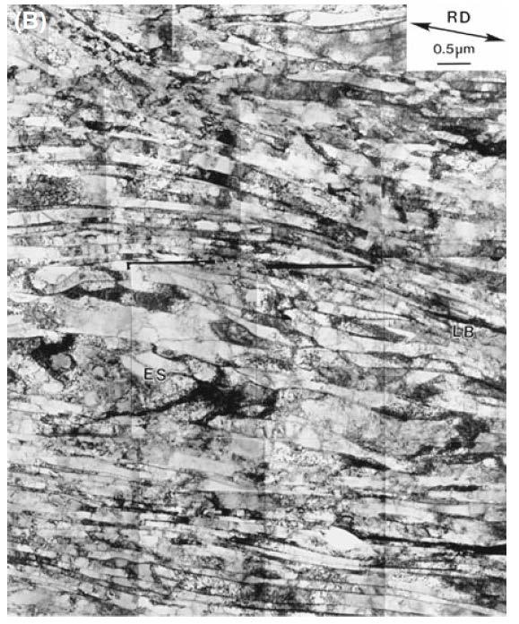

20 Dislocation Pairs, Arrays, and Tangles

21 Surface Effects Dislocation strain fields are long range, but we often assign them a cut-off radius of 50nm. However the specimen thickness might only be 50nm or less. The surface can affect the strain field of the dislocation, and vice versa.


22 Dislocations and Interfaces Misfit dislocations accommodate the different in lattice parameter between two well-aligned crystalline. Transformation dislocations are the dislocations that move to create a change in orientation or phase.

23 Dislocations and Interfaces


24 Volume Defects and Particls
25 Weak-Beam Dark-Field Microscopy
26 Weak-Beam Dark-Field image

27 Intensity in WBDF Images In a perfect crystal the intensity of the diffracted beam in two beam condition: In the WB technique we increase s to about 0.2 nm -1 so as to increase s eff. If s >> ξ g -2 then s s eff and indenpendent of ξ g except as a scaling factor for t, this is known as the kinematical equation, which cannot be applied for all s unless the thickness, t is also very small.
28 How To Do WBDF CDF with small objective aperture on optimized thickness


29 Thickness Fringes in Weak-Beam Images


30 Imaging Strain Field


31 Weak-Beam Images of Dissociated Dislocations In WB image with g b T = 2, each of the partial dislocations will generally give rise to a single peak in the image which is close to the dislocation core. You can relate the separation of the peaks in the image to the separation of the partial dislocations.
32 High-Resolution TEM
33 The Role of An Optical System h(r) describes how a point spreads into a disk, it is known as the point-spread function or smearing function, and g(r) is called the convolution of f(r) with h(r).
34 The Fourier transform Here u is a reciprocal-lattice vector. This is to say g(r) is a combination of the possible values of G(u), where G(u) is known as the Fourier transform of g(r). A(u): Aperture function; E(u): envelope function (attenuation of the wave); B(u): aberration function; H(u): the contrast transfer function (CTF). Each point in the specimen plane is transformed into an extended region (or disk) in the final image. Each point in the final image has contributions from many points in the specimen.
35 Contrast Transfer Theory - wikipedia Contrast Transfer Theory provides a quantitative method to translate the exit wavefunction to a final image. Part of the analysis is based on Fourier transforms of the electron beam wavefunction. When an electron wavefunction passes through a lens, the wavefunction goes through a Fourier transform. This is a concept from Fourier optics. Contrast Transfer Theory consists of four main operations: Take the Fourier transform of the exit wave to obtain the wave amplitude in back focal plane of objective lens Modify the wavefunction in reciprocal space by a phase factor, also known as the Phase Contrast Transfer Function, to account for aberrations Inverse Fourier transform the modified wavefunction to obtain the wavefunction in the image plane Find the square modulus of the wavefunction in the image plane to find the image intensity (this is the signal that is recorded on a detector, and creates an image)
36 The Transfer function If the specimen acts as a weak-phase object, then the transfer function T(u) is sometimes called the CTF, because there is no amplitude contribution, and the output of the transmission system is an observable quantity (image contrast). χ(u) is the phase-distortion function has the form of a phase shift expressed as 2π/λ times the path difference traveled by those waves affected by spherical aberration (C s ), defocus ( z), and astigmatis (C a ). The CTF shows maxima (meaning maximum transfer of contrast) whenever the phase-distortion function assumes multiple odd values of ±π/2. zero contrast occurs for χ(u) = multiple ±π. When T(u) is negative, positive phase contrast results, meaning that atoms would appear dark against a bright background. When T(u) is positive, negative phase contrast results, meaning that atoms would appear bright against a dark background. When T(u) = 0, there is no detail in the image for this value of u. (note that we assume here that C s > 0).
37 More on χ(u), sinχ(u), and cosχ(u) sinχ starts at 0 and decreases. When u is small, the f term dominates. sinχ first crosses the u-axis at u1 and then repeatedly crosses the u-axis as u increases.
38 Scherzer Defocus Scherzer found that the CTF could be optimized by balancing the effect of spherical aberration against a particular negative value of f. this value has come to be known as Scherzer defocus, f Sch which occurs at Scherzer resolution:
39 Simulation of sinχ
40 Experimental Considerations Remarks: Thinner specimen, ideal case single scattering event. Coma-free alignment to align the beam with optic axis. Specimen orientation is very critical for HRTEM. The Future For HRTEM C s -corrected TEM: C s is zero or as a variable like underfocus. Resolution limit will be determined by C c.
: for chromatic aberration E s (u): for the source dependence due to the small spread of angles from the probe. E d (u): for specimen drift. E v (u): for specimen vibration.")
41 FEG TEMs and The Information Limit The information limit is determined by the envelope function. E c (u): for chromatic aberration E s (u): for the source dependence due to the small spread of angles from the probe. E d (u): for specimen drift. E v (u): for specimen vibration. E D (u): for the detector. nce/information_limit.htm Information limit goes well beyond point resolution limit for FEG microscopes (due to high spatial and temporal coherency). For the microscope with thermionic electron sources, the info limit usually coincides with the point resolution. Phase contrast images are directly interpretable only up to the point resolution (Scherzer resolution limit) If the information limit is beyond the point resolution limit, one needs to use image simulation software to interpret any detail beyond point resolution limit.
. Focal series of image are a challenge with a large range of f values.")
42 Some Difficulties In Using An FEG A cold FEG has a small emitter area and Schotty emitter has a source diameter 10 times greater, but with a decrease in spatial coherence and a larger energy spread. Correcting astigmatism is very tricky. Need on-line processing (live FFT). Focal series of image are a challenge with a large range of f values. Image delocalization occurs when detail in the image is displaced relative to its true location in the specimen.

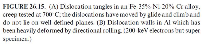
43 Selectively Imaging Sublattices


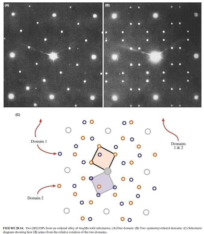
44 Interfaces And Surfaces The fundamental requirement is that the interface plane must be parallel to the electron beam.

45 Incommensurate Structures

46 Quasicryatals HRTEM excels when materials are ordered on a local scale. For HRTEM, we need the atoms to align in columns because this is a projection technique, but the distribution along the column is not so critical. And we can t determine it without tilting to another projection in the perfect crystal. SAD and HRTEM should be used in a complementary fashion.

47 Single Atoms Observation by Parsons et al. with dedicated STEM: uranium atoms in molecule matrix.
48 homework Question homework: Reading and summary
Transmission Electron Microscopy
 L. Reimer H. Kohl Transmission Electron Microscopy Physics of Image Formation Fifth Edition el Springer Contents 1 Introduction... 1 1.1 Transmission Electron Microscopy... 1 1.1.1 Conventional Transmission
High-Resolution. Transmission. Electron Microscopy
 Part 4 High-Resolution Transmission Electron Microscopy 186 Significance high-resolution transmission electron microscopy (HRTEM): resolve object details smaller than 1nm (10 9 m) image the interior of
Experimental methods in Physics. Electron Microscopy. Basic Techniques (MEP-I) SEM, TEM
 SEM, TEM") Experimental methods in Physics Electron Microscopy Basic Techniques (MEP-I) SEM, TEM Advanced Techniques (MEP-II) HR-TEM, STEM Analytical-TEM 3D-Microscopy Spring 2012 Experimental Methods in Physics
Experimental methods in Physics Electron Microscopy Basic Techniques (MEP-I) SEM, TEM Advanced Techniques (MEP-II) HR-TEM, STEM Analytical-TEM 3D-Microscopy Spring 2012 Experimental Methods in Physics
Transmission Electron Microscopy and Diffractometry of Materials
 Brent Fultz James Howe Transmission Electron Microscopy and Diffractometry of Materials Fourth Edition ~Springer 1 1 Diffraction and the X-Ray Powder Diffractometer 1 1.1 Diffraction... 1 1.1.1 Introduction
Spatial Frequency and Transfer Function. columns of atoms, where the electrostatic potential is higher than in vacuum
 Image Formation Spatial Frequency and Transfer Function consider thin TEM specimen columns of atoms, where the electrostatic potential is higher than in vacuum electrons accelerate when entering the specimen
Weak-Beam Dark-Field Technique
 Basic Idea recall bright-field contrast of dislocations: specimen close to Bragg condition, s î 0 Weak-Beam Dark-Field Technique near the dislocation core, some planes curved to s = 0 ) strong Bragg reflection
CHEM 681 Seminar Mingqi Zhao April 20, 1998 Room 2104, 4:00 p.m. High Resolution Transmission Electron Microscopy: theories and applications
 CHEM 681 Seminar Mingqi Zhao April 20, 1998 Room 2104, 4:00 p.m. High Resolution Transmission Electron Microscopy: theories and applications In materials science, people are always interested in viewing
Chapter 4 Imaging Lecture 24
 Chapter 4 Imaging Lecture 4 d (110) Final Exam Notice Time and Date: :30 4:30 PM, Wednesday, Dec. 10, 08. Place: Classroom CHEM-10 Coverage: All contents after midterm Open note Term project is due today
Dislocation networks in graphite
 Dislocation networks in graphite High Resolution Microscop With Reference to Lattice Fringe Imaging in a TEM f f r Real space Specimen Reciprocal space hr Point spread function Diffraction pattern Back
CHEM-E5225 :Electron Microscopy. Diffraction 1
 CHEM-E5225 :Electron Microscopy Diffraction 1 2018-10-15 Yanling Ge Text book: Transmission electron microscopy by David B Williams & C. Barry Carter. 2009, Springer Outline Diffraction in TEM Thinking
Linear Systems. : object : image. Describes the output of a linear system. input. output. Impulse response function
 Linear Systems Describes the output of a linear system Gx FxHx- xdx FxHx F x G x x output input Impulse response function H x xhx- xdx x If the microscope is a linear system: : object : image G x S F x
Overview of scattering, diffraction & imaging in the TEM
 Overview of scattering, diffraction & imaging in the TEM Eric A. Stach Purdue University Scattering Electrons, photons, neutrons Radiation Elastic Mean Free Path (Å)( Absorption Length (Å)( Minimum Probe
Chapter 4 Imaging. Lecture 21. d (110) Chem 793, Fall 2011, L. Ma
 Chem 793, Fall 2011, L. Ma") Chapter 4 Imaging Lecture 21 d (110) Imaging Imaging in the TEM Diraction Contrast in TEM Image HRTEM (High Resolution Transmission Electron Microscopy) Imaging or phase contrast imaging STEM imaging a
Chapter 4 Imaging Lecture 21 d (110) Imaging Imaging in the TEM Diraction Contrast in TEM Image HRTEM (High Resolution Transmission Electron Microscopy) Imaging or phase contrast imaging STEM imaging a
Part 3 - Image Formation
 Part 3 - Image Formation Three classes of scattering outcomes Types of electron microscopes Example SEM image: fly nose Example TEM image: muscle Skeletal muscle. Cell and Tissue Ultrastructure Mercer
Transmission Electron Microscope. Experimental Instruction
 Transmission Electron Microscope Experimental Instruction In advanced practical course [F-Praktikum] Date: April 2017 Contents 1 Task 3 2 Theoretical Basics 3 2.1 Bragg Diffraction......................................
Supplementary Figure 1: Example non-overlapping, binary probe functions P1 (~q) and P2 (~q), that add to form a top hat function A(~q).
 and P2 (~q), that add to form a top hat function A(~q).") Supplementary Figures P(q) A(q) + Function Value P(q) qmax = Supplementary Figure : Example non-overlapping, binary probe functions P (~q) and P (~q), that add to form a top hat function A(~q). qprobe
Supplementary Figures P(q) A(q) + Function Value P(q) qmax = Supplementary Figure : Example non-overlapping, binary probe functions P (~q) and P (~q), that add to form a top hat function A(~q). qprobe
April 10th-12th, 2017
 Thomas LaGrange, Ph.D. Faculty Lecturer and Senior Staff Scientist Introduction: Basics of Transmission Electron Microscopy (TEM) TEM Doctoral Course MS-637 April 10th-12th, 2017 Outline 1. What is microcopy?
Elastic and Inelastic Scattering in Electron Diffraction and Imaging
 Elastic and Inelastic Scattering in Electron Diffraction and Imaging Contents Introduction Symbols and definitions Part A Diffraction and imaging of elastically scattered electrons Chapter 1. Basic kinematical
DIFFRACTION PHYSICS THIRD REVISED EDITION JOHN M. COWLEY. Regents' Professor enzeritus Arizona State University
 DIFFRACTION PHYSICS THIRD REVISED EDITION JOHN M. COWLEY Regents' Professor enzeritus Arizona State University 1995 ELSEVIER Amsterdam Lausanne New York Oxford Shannon Tokyo CONTENTS Preface to the first
Physical Principles of Electron Microscopy. 2. Electron Optics
 Physical Principles of Electron Microscopy 2. Electron Optics Ray Egerton University of Alberta and National Institute of Nanotechnology Edmonton, Canada www.tem-eels.ca regerton@ualberta.ca Properties
High-Resolution Transmission Electron Microscopy
 Chapter 2 High-Resolution Transmission Electron Microscopy The most fundamental imaging mode of a transmission electron microscope is realized by illuminating an electron-transparent specimen with a broad
The Basic of Transmission Electron Microscope. Text book: Transmission electron microscopy by David B Williams & C. Barry Carter.
 The Basic of Transmission Electron Microscope Text book: Transmission electron microscopy by David B Williams & C. Barry Carter. 2009, Springer Background survey http://presemo.aalto.fi/tem1 Microscopy
n The visual examination of the image of a point source is one of the most basic and important tests that can be performed.
 8.2.11 Star Test n The visual examination of the image of a point source is one of the most basic and important tests that can be performed. Interpretation of the image is to a large degree a matter of
Conventional Transmission Electron Microscopy. Introduction. Text Books. Text Books. EMSE-509 CWRU Frank Ernst
 Text Books Conventional Transmission Electron Microscopy EMSE-509 CWRU Frank Ernst D. B. Williams and C. B. Carter: Transmission Electron Microscopy, New York: Plenum Press (1996). L. Reimer: Transmission
Lecture 6. What is contrast? Eyes: < 5% - can t detect <10% - difficult Enhance digital image electronically I I C I
 Phae Contrat Lecture 6 Scattering/Amplitude Contrat BF/DF: thickne, tilt Low-medium magnification Application Crytal defect: dilocation, tacking fault, phae boundarie, precipitate, defect cluter Contrat:
Chapter 20: Convergent-beam diffraction Selected-area diffraction: Influence of thickness Selected-area vs. convergent-beam diffraction
 1 Chapter 0: Convergent-beam diffraction Selected-area diffraction: Influence of thickness Selected-area diffraction patterns don t generally get much better when the specimen gets thicker. Sometimes a
Wavefront Sensing using Polarization Shearing Interferometer. A report on the work done for my Ph.D. J.P.Lancelot
 Wavefront Sensing using Polarization Shearing Interferometer A report on the work done for my Ph.D J.P.Lancelot CONTENTS 1. Introduction 2. Imaging Through Atmospheric turbulence 2.1 The statistics of
AP5301/ Name the major parts of an optical microscope and state their functions.
 Review Problems on Optical Microscopy AP5301/8301-2015 1. Name the major parts of an optical microscope and state their functions. 2. Compare the focal lengths of two glass converging lenses, one with
NANO 703-Notes. Chapter 21: Using CBED
 1 Chapter 21: Using CBED CBED features Common features in a CBED pattern can be seen in the example below. Excess and defect ZOLZ Kikuchi lines are fairly strong and broad. (Defect) HOLZ (Bragg) lines
Electron microscopy in molecular cell biology I
 Electron microscopy in molecular cell biology I Electron optics and image formation Werner Kühlbrandt Max Planck Institute of Biophysics chemistry biology Objects of interest Galaxy 10 6 light years 10
These authors contributed equally to this work. 1. Structural analysis of as-deposited PbS quantum dots by Atomic Layer Deposition (ALD)
") Supporting information for: Atomic Layer Deposition of Lead Sulfide Quantum Dots on Nanowire Surfaces Neil P. Dasgupta 1,*,, Hee Joon Jung 2,, Orlando Trejo 1, Matthew T. McDowell 2, Aaron Hryciw 3, Mark
Supporting information for: Atomic Layer Deposition of Lead Sulfide Quantum Dots on Nanowire Surfaces Neil P. Dasgupta 1,*,, Hee Joon Jung 2,, Orlando Trejo 1, Matthew T. McDowell 2, Aaron Hryciw 3, Mark
PROBE AND OBJECT FUNCTION RECONSTRUCTION IN INCOHERENT SCANNING TRANSMISSION ELECTRON MICROSCOPE IMAGING
 Scanning Microscopy Vol. 11, 1997 (Pages 81-90) 0891-7035/97$5.00+.25 Scanning Microscopy International, Chicago Probe (AMF and O Hare), object IL function 60666 reconstruction USA PROBE AND OBJECT FUNCTION
Aberration-corrected TEM studies on interface of multilayered-perovskite systems
 Aberration-corrected TEM studies on interface of multilayered-perovskite systems By Lina Gunawan (0326114) Supervisor: Dr. Gianluigi Botton November 1, 2006 MSE 702(1) Presentation Outline Literature Review
Characterization of crystallographic defects in LaNiO 3 through TEM image simulations
 Characterization of crystallographic defects in LaNiO 3 through TEM image simulations Author: Joan Carles Bastons Garcia. Departament d Electrònica, Universitat de Barcelona Advisors: Sònia Estradé Albiol
Structure analysis: Electron diffraction LEED TEM RHEED
 Structure analysis: Electron diffraction LEED: Low Energy Electron Diffraction SPA-LEED: Spot Profile Analysis Low Energy Electron diffraction RHEED: Reflection High Energy Electron Diffraction TEM: Transmission
PRINCIPLES OF PHYSICAL OPTICS
 PRINCIPLES OF PHYSICAL OPTICS C. A. Bennett University of North Carolina At Asheville WILEY- INTERSCIENCE A JOHN WILEY & SONS, INC., PUBLICATION CONTENTS Preface 1 The Physics of Waves 1 1.1 Introduction
Optics Optical Testing and Testing Instrumentation Lab
 Optics 513 - Optical Testing and Testing Instrumentation Lab Lab #6 - Interference Microscopes The purpose of this lab is to observe the samples provided using two different interference microscopes --
November 30th -December 2 nd, st 2nd 3rd. 8:15 7)HRTEM 10) TEM imaging and diffraction examples. 9:15 8)HRTEM 10) Diffraction going further
HRTEM 10) TEM imaging and diffraction examples. 9:15 8)HRTEM 10) Diffraction going further") Thomas LaGrange, Ph.D. Faculty and Staff Scientist Introduction: Basics of Transmission Electron Microscopy (TEM) TEM Doctoral Course MS-637 November 30th -December 2 nd, 2015 Planning MSE-637 TEM -basics
Thomas LaGrange, Ph.D. Faculty and Staff Scientist Introduction: Basics of Transmission Electron Microscopy (TEM) TEM Doctoral Course MS-637 November 30th -December 2 nd, 2015 Planning MSE-637 TEM -basics
Detecting strain in scanning transmission electron microscope images. Part II Thesis
 Detecting strain in scanning transmission electron microscope images Part II Thesis Ina M. Sørensen Mansfield College, Oxford 10th of June, 2015 1 Abstract Scanning Transmission Electron Microscopes (STEM)
MSE 321 Structural Characterization
 Auger Spectroscopy Auger Electron Spectroscopy (AES) Scanning Auger Microscopy (SAM) Incident Electron Ejected Electron Auger Electron Initial State Intermediate State Final State Physical Electronics
CHEM-E5225 :Electron Microscopy X-Ray Spectrometry
 CHEM-E5225 :Electron Microscopy X-Ray Spectrometry 2016.11 Yanling Ge Outline X-ray Spectrometry X-ray Spectra and Images Qualitative and Quantitative X-ray Analysis and Imaging Discussion of homework
Resolution of coherent and incoherent imaging systems reconsidered - Classical criteria and a statistical alternative
 Resolution of coherent and incoherent imaging systems reconsidered - Classical criteria and a statistical alternative Sandra Van Aert and Dirk Van Dyck University of Antwerp, Department of Physics, Groenenborgerlaan
Experimental Determination of Crystal Structure
 Experimental Determination of Crystal Structure Branislav K. Nikolić Department of Physics and Astronomy, University of Delaware, U.S.A. PHYS 624: Introduction to Solid State Physics http://www.physics.udel.edu/~bnikolic/teaching/phys624/phys624.html
CHARA Meeting 2017 Pasadena, California
 MORE AUTOMATION Laszlo Sturmann M7 ACTUATORS LAB. LASER ALIGNMENT TELESCOPE OPTICAL ALIGNMENT NEW ACTUATORS REMOTELY ACTUATED M7 MOUNT MOTIVATION THE PRECISION OF THE COUDE ALIGNMENT WAS NOT SUFFICIENT
Praktikum zur. Materialanalytik
 Praktikum zur Materialanalytik Energy Dispersive X-ray Spectroscopy B513 Stand: 19.10.2016 Contents 1 Introduction... 2 2. Fundamental Physics and Notation... 3 2.1. Alignments of the microscope... 3 2.2.
sin" =1.22 # D "l =1.22 f# D I: In introduction to molecular electron microscopy - Imaging macromolecular assemblies
 I: In introduction to molecular electron microscopy - Imaging macromolecular assemblies Yifan Cheng Department of Biochemistry & Biophysics office: GH-S472D; email: ycheng@ucsf.edu 2/20/2015 - Introduction
Part 1 - Basic Interferometers for Optical Testing
 Part 1 - Basic Interferometers for Optical Testing Two Beam Interference Fizeau and Twyman-Green interferometers Basic techniques for testing flat and spherical surfaces Mach-Zehnder Zehnder,, Scatterplate
IMAGING DIFFRACTION SPECTROSCOPY
 TEM Techniques TEM/STEM IMAGING DIFFRACTION SPECTROSCOPY Amplitude contrast (diffracion contrast) Phase contrast (highresolution imaging) Selected area diffraction Energy dispersive X-ray spectroscopy
Interference, Diffraction and Fourier Theory. ATI 2014 Lecture 02! Keller and Kenworthy
 Interference, Diffraction and Fourier Theory ATI 2014 Lecture 02! Keller and Kenworthy The three major branches of optics Geometrical Optics Light travels as straight rays Physical Optics Light can be
Introduction to Crystallography and Electron Diffraction
 Introduction to Crystallography and Electron Diffraction Marc De Graef Carnegie Mellon University Sunday July 24, 2016 M&M Conference, July 24-28, 2016, Columbus, OH Overview Introductory remarks Basic
There and back again A short trip to Fourier Space. Janet Vonck 23 April 2014
 There and back again A short trip to Fourier Space Janet Vonck 23 April 2014 Where can I find a Fourier Transform? Fourier Transforms are ubiquitous in structural biology: X-ray diffraction Spectroscopy
Optics.
 Optics www.optics.rochester.edu/classes/opt100/opt100page.html Course outline Light is a Ray (Geometrical Optics) 1. Nature of light 2. Production and measurement of light 3. Geometrical optics 4. Matrix
PH 222-3A Spring 2010
 PH -3A Spring 010 Interference Lecture 6-7 Chapter 35 (Halliday/Resnick/Walker, Fundamentals of Physics 8 th edition) 1 Chapter 35 Interference The concept of optical interference is critical to understanding
Molecular electron microscopy
 Molecular electron microscopy - Imaging macromolecular assemblies Yifan Cheng Department of Biochemistry & Biophysics office: GH-S427B; email: ycheng@ucsf.edu 2/22/2013 - Introduction of Molecular Microscopy:
Formation of the diffraction pattern in the transmision electron microscope
 Formation of the diffraction pattern in the transmision electron microscope based on: J-P. Morniroli: Large-angle convergent-beam diffraction (LACBED), 2002 Société Française des Microscopies, Paris. Selected
Structure of Surfaces
 Structure of Surfaces C Stepped surface Interference of two waves Bragg s law Path difference = AB+BC =2dsin ( =glancing angle) If, n =2dsin, constructive interference Ex) in a cubic lattice of unit cell
Transmission Electron Microscopy. Part #1 Diffraction Conventional Imaging
 Transmission Electron Microscopy Part #1 Diffraction Conventional Imaging Nicolas Menguy Institut de Minéralogie, de Physique des Matériaux et de Cosmochimie Outline Part 1 : Conventional TEM - Transmission
TrueImage A Software Package for Focal-Series Reconstruction in HRTEM
 TrueImage A Software Package for Focal-Series Reconstruction in HRTEM C. Kübel 1 and A. Thust 2 1) FEI Company, Achtseweg Noord 5, 5651 GG Eindhoven, The Netherlands. 2) Forschungszentrum Jülich GmbH,
Energy-Filtering. Transmission. Electron Microscopy
 Part 3 Energy-Filtering Transmission Electron Microscopy 92 Energy-Filtering TEM Principle of EFTEM expose specimen to mono-energetic electron radiation inelastic scattering in the specimen poly-energetic
GBS765 Electron microscopy
 GBS765 Electron microscopy Lecture 1 Waves and Fourier transforms 10/14/14 9:05 AM Some fundamental concepts: Periodicity! If there is some a, for a function f(x), such that f(x) = f(x + na) then function
Laser Optics-II. ME 677: Laser Material Processing Instructor: Ramesh Singh 1
 Laser Optics-II 1 Outline Absorption Modes Irradiance Reflectivity/Absorption Absorption coefficient will vary with the same effects as the reflectivity For opaque materials: reflectivity = 1 - absorptivity
Approximations for Dynamical Calculations of Microdiffraction Patterns and Images of Defects
 112 COMPUTED ELECTRON MICROSCOPE IMAGES OF ATOMIC DEFECTS HAUBOLD, H. G. (1975). J. Appl. Cryst. 8, 175-183. IIJIMA, S. (1976). 34th Ann. Proc. Electron Microsc. Soc. Am. Edited by G. W. BAILEY, pp. 490-491.
Good Diffraction Practice Webinar Series
 Good Diffraction Practice Webinar Series High Resolution X-ray Diffractometry (1) Mar 24, 2011 www.bruker-webinars.com Welcome Heiko Ress Global Marketing Manager Bruker AXS Inc. Madison, Wisconsin, USA
Astronomy 203 practice final examination
 Astronomy 203 practice final examination Fall 1999 If this were a real, in-class examination, you would be reminded here of the exam rules, which are as follows: You may consult only one page of formulas
Light Propagation in Free Space
 Intro Light Propagation in Free Space Helmholtz Equation 1-D Propagation Plane waves Plane wave propagation Light Propagation in Free Space 3-D Propagation Spherical Waves Huygen s Principle Each point
Everhart-Thornley detector
 SEI Detector Everhart-Thornley detector Microscope chamber wall Faraday cage Scintillator Electrons in Light pipe Photomultiplier Electrical signal out Screen Quartz window +200 V +10 kv Always contains
Introduction to crystallography The unitcell The resiprocal space and unitcell Braggs law Structure factor F hkl and atomic scattering factor f zθ
 Introduction to crystallography The unitcell The resiprocal space and unitcell Braggs law Structure factor F hkl and atomic scattering factor f zθ Introduction to crystallography We divide materials into
Solid State Physics Lecture 3 Diffraction and the Reciprocal Lattice (Kittel Ch. 2)
") Solid State Physics 460 - Lecture 3 Diffraction and the Reciprocal Lattice (Kittel Ch. 2) Diffraction (Bragg Scattering) from a powder of crystallites - real example of image at right from http://www.uni-wuerzburg.de/mineralogie/crystal/teaching/pow.html
Solid State Physics 460 - Lecture 3 Diffraction and the Reciprocal Lattice (Kittel Ch. 2) Diffraction (Bragg Scattering) from a powder of crystallites - real example of image at right from http://www.uni-wuerzburg.de/mineralogie/crystal/teaching/pow.html
5. LIGHT MICROSCOPY Abbe s theory of imaging
 5. LIGHT MICROSCOPY. We use Fourier optics to describe coherent image formation, imaging obtained by illuminating the specimen with spatially coherent light. We define resolution, contrast, and phase-sensitive
2.1 Thin Film Processing by Pulsed Laser Deposition ( Basic principles and
 CHAPTER 2 RESEARCH METHODOLOGY 2.1 Thin Film Processing by Pulsed Laser Deposition ( Basic principles and advantages) The current interest in the use of lasers, either for scientific investigations or
MSE 321 Structural Characterization
 Optical Microscope Plan Lenses In an "ideal" single-element lens system all planar wave fronts are focused to a point at distance f from the lens; therefore: Image near the optical axis will be in perfect
SIMULATION OF TRANSMISSION AND SCANNING TRANSMISSION ELECTRON MICROSCOPIC IMAGES CONSIDERING ELASTIC AND THERMAL DIFFUSE SCATTERING
 Scanning Microscopy Vol. 11, 1997 (Pages 277-286) 0891-7035/97$5.00+.25 Scanning Microscopy International, Chicago (AMF Simulation O Hare), of TEM IL 60666 and STEM USA images SIMULATION OF TRANSMISSION
Transmission Electron Microscopy for metrology and characterization of semiconductor devices
 Transmission Electron Microscopy for metrology and characterization of semiconductor devices Bert Freitag, Laurens Kwakman, Ivan Lazic and Frank de Jong FEI / ThermoFisher Scientific, Achtseweg Noord 5,
Image Assessment San Diego, November 2005
 Image Assessment San Diego, November 005 Pawel A. Penczek The University of Texas Houston Medical School Department of Biochemistry and Molecular Biology 6431 Fannin, MSB6.18, Houston, TX 77030, USA phone:
Imaging Methods: Scanning Force Microscopy (SFM / AFM)
") Imaging Methods: Scanning Force Microscopy (SFM / AFM) The atomic force microscope (AFM) probes the surface of a sample with a sharp tip, a couple of microns long and often less than 100 Å in diameter.
Imaging Methods: Scanning Force Microscopy (SFM / AFM) The atomic force microscope (AFM) probes the surface of a sample with a sharp tip, a couple of microns long and often less than 100 Å in diameter.
MSE 321 Structural Characterization
 Auger Spectroscopy Auger Electron Spectroscopy (AES) Scanning Auger Microscopy (SAM) Incident Electron Ejected Electron Auger Electron Initial State Intermediate State Final State Physical Electronics
Optical/IR Observational Astronomy Telescopes I: Telescope Basics. David Buckley, SAAO
 David Buckley, SAAO 17 Feb 2010 1 Some other Telescope Parameters 1. Plate Scale This defines the scale of an image at the telescopes focal surface For a focal plane, with no distortion, this is just related
* AIT-4: Aberrations. Copyright 2006, Regents of University of California
 Advanced Issues and Technology (AIT) Modules Purpose: Explain the top advanced issues and concepts in optical projection printing and electron-beam lithography. AIT-: LER and Chemically Amplified Resists
X-ray, Neutron and e-beam scattering
 X-ray, Neutron and e-beam scattering Introduction Why scattering? Diffraction basics Neutrons and x-rays Techniques Direct and reciprocal space Single crystals Powders CaFe 2 As 2 an example What is the
Structural Characterization of Nanoparticles
 Structural Characterization of Nanoparticles Nicola Pinna Max Planck Institute of Colloids and Interfaces e-mail: pinna@mpikg-golm.mpg.de - http://www.pinna.cx Plan 1. Transmission Electron Microscopy
*Specifications subject to change without notice.
 The Power of STEM *Specifications subject to change without notice. No. 1301G040C 1101E010C Printed in Japan, Kp Atomic Resolution Analytical Microscope Serving Advanced Technology Atomic Resolution Analytical
AOL Spring Wavefront Sensing. Figure 1: Principle of operation of the Shack-Hartmann wavefront sensor
 AOL Spring Wavefront Sensing The Shack Hartmann Wavefront Sensor system provides accurate, high-speed measurements of the wavefront shape and intensity distribution of beams by analyzing the location and
Michelson Interferometer
 Michelson Interferometer Objective Determination of the wave length of the light of the helium-neon laser by means of Michelson interferometer subsectionprinciple and Task Light is made to produce interference
A beam of coherent monochromatic light from a distant galaxy is used in an optics experiment on Earth.
 Waves_P2 [152 marks] A beam of coherent monochromatic light from a distant galaxy is used in an optics experiment on Earth. The beam is incident normally on a double slit. The distance between the slits
Motion of Light Adatoms and Molecules on the Surface of Few-Layer Graphene
 Supporting information Motion of Light Adatoms and Molecules on the Surface of Few-Layer Graphene Franziska Schäffel 1,*, Mark Wilson 2, Jamie H. Warner 1 1 Department of Materials, University of Oxford,
Chapter 35. Interference
 Chapter 35 Interference The concept of optical interference is critical to understanding many natural phenomena, ranging from color shifting in butterfly wings to intensity patterns formed by small apertures.
Waves Part III Electromagnetic waves
 Waves Part III Electromagnetic waves Electromagnetic (light) waves Transverse waves Transport energy (and momentum) Can travel through vacuum (!) and certain solids, liquids and gases Do not transport
Supplementary Information
 Supplementary Information Supplementary Figure 1. X-ray diffraction patterns of (a) pure LDH, (b) AuCl 4 ion-exchanged LDH and (c) the Au/LDH hybrid catalyst. The refined cell parameters for pure, ion-exchanged,
0 of the same magnitude. If we don t use an OA and ignore any damping, the CTF is
 1 4. Image Simulation Influence of C Spherical aberration break the ymmetry that would otherwie exit between overfocu and underfocu. One reult i that the fringe in the FT of the CTF are generally farther
Optical/IR Observational Astronomy Telescopes I: Optical Principles. David Buckley, SAAO. 24 Feb 2012 NASSP OT1: Telescopes I-1
 David Buckley, SAAO 24 Feb 2012 NASSP OT1: Telescopes I-1 1 What Do Telescopes Do? They collect light They form images of distant objects The images are analyzed by instruments The human eye Photographic
= 6 (1/ nm) So what is probability of finding electron tunneled into a barrier 3 ev high?
 So what is probability of finding electron tunneled into a barrier 3 ev high?") STM STM With a scanning tunneling microscope, images of surfaces with atomic resolution can be readily obtained. An STM uses quantum tunneling of electrons to map the density of electrons on the surface
STM STM With a scanning tunneling microscope, images of surfaces with atomic resolution can be readily obtained. An STM uses quantum tunneling of electrons to map the density of electrons on the surface
Design and Correction of optical Systems
 Design and Correction of optical Systems Part 10: Performance criteria 1 Summer term 01 Herbert Gross Overview 1. Basics 01-04-18. Materials 01-04-5 3. Components 01-05-0 4. Paraxial optics 01-05-09 5.
Supplementary Information
 Supplementary Information Supplementary Figures Supplementary figure S1: Characterisation of the electron beam intensity profile. (a) A 3D plot of beam intensity (grey value) with position, (b) the beam
INTRODUCTION TO THE PETROGRAPHIC MICROSCOPE AND RELIEF, BECKE LINE, AND OBLIQUE ILLUMINATION
 GLY 4200C LAB EXERCISE 10 INTRODUCTION TO THE PETROGRAPHIC MICROSCOPE AND RELIEF, BECKE LINE, AND OBLIQUE ILLUMINATION Locate all of the following microscope parts. Refer to Figure1 1) Eyepiece (note the
Phase Retrieval for the Hubble Space Telescope and other Applications Abstract: Introduction: Theory:
 Phase Retrieval for the Hubble Space Telescope and other Applications Stephanie Barnes College of Optical Sciences, University of Arizona, Tucson, Arizona 85721 sab3@email.arizona.edu Abstract: James R.
Optical/IR Observational Astronomy Telescopes I: Telescope Basics. David Buckley, SAAO
 David Buckley, SAAO 27 Feb 2012 1 Some other Telescope Parameters 1. Plate Scale This defines the scale of an image at the telescopes focal surface For a focal plane, with no distortion, this is just related
Crystal planes. Neutrons: magnetic moment - interacts with magnetic materials or nuclei of non-magnetic materials. (in Å)
") Crystallography: neutron, electron, and X-ray scattering from periodic lattice, scattering of waves by periodic structures, Miller indices, reciprocal space, Ewald construction. Diffraction: Specular,
Crystallography: neutron, electron, and X-ray scattering from periodic lattice, scattering of waves by periodic structures, Miller indices, reciprocal space, Ewald construction. Diffraction: Specular,
Supplementary Information
 Supplementary Information Direct observation of crystal defects in an organic molecular crystals of copper hexachlorophthalocyanine by STEM-EELS Mitsutaka Haruta*, Hiroki Kurata Institute for hemical Research,
Surface Sensitivity & Surface Specificity
 Surface Sensitivity & Surface Specificity The problems of sensitivity and detection limits are common to all forms of spectroscopy. In its simplest form, the question of sensitivity boils down to whether
X-Ray Diffraction as a key to the Structure of Materials Interpretation of scattering patterns in real and reciprocal space
 X-Ray Diffraction as a key to the Structure of Materials Interpretation of scattering patterns in real and reciprocal space Tobias U. Schülli, X-ray nanoprobe group ESRF OUTLINE 1 Internal structure of