n The visual examination of the image of a point source is one of the most basic and important tests that can be performed.
|
|
|
- Brett Harper
- 5 years ago
- Views:
Transcription
1 Star Test n The visual examination of the image of a point source is one of the most basic and important tests that can be performed. Interpretation of the image is to a large degree a matter of experience. Should be a dynamic process where the observer probes through focus and across the field. Magnifying power should be such that the smallest significant detail subtends 10 to 15 minutes of arc at the eye. The numerical aperture of the viewing optics must be large enough to collect the entire cone of light from the optics under test. Page 1
2 Airy Disk n For perfect optics the image of a point source as seen at best focus is called the Airy disk. The diameter of the central core is equal to 2.44λf#, where f# is the f/number of the converging light beam. In the visible, the diameter of the central core is approximately equal to the f# in microns. The central core contains approximately 84% of the total amount of light, while the total amount of light contained within the first, second, and third rings is approximately 91%, 94%, and 95%, respectively. If the microscope is moved back and forth along the axis, the image will be seen to go in and out of focus. A perfect image will appear totally symmetrical on opposite sides of focus Page 2
3 Spot Size Spherical Aberration ΔW = ΔW s ρ 4 ε y = R h ΔW y = R h 4ΔW = 8 $ R ' s & )ΔW s % 2h ( Therefore, 2ε y =16 f # ΔW sph The minimum blur diameter is ¼ of this or Minimum Blur Diameter = 4 f # ΔW sph Page 3
4 Spot Size Astigmatism ΔW = ΔW a y 2 ε y = R h ΔW y = R h 2yΔW = 4 $ R ' a & )ΔW a % 2h ( Therefore, 2ε y = 8 f # ΔW ast Blur diameter at circle of least confusion is ½ of this or Minimum Blur Diameter = 4 f # ΔW ast Page 4
5 Spot Size Coma ΔW = ΔW c ρ 3 Cos[ φ] = ΔW ( c x 2 + y 2 ) y ε y = R h ΔW y = R h ΔW c x 2 + 3y 2 ( ) = R h ΔW c ρ 2 + 2y 2 ( ) At y 2 =1 ε y = 2 R 2h ΔW c(3) = 6 f # ΔW coma The sagittal coma is 1/3 of this or Diameter of Blur Circle = 4 f # ΔW coma Therefore, the minimum spot diameter for third-order spherical, the width of the coma image (2/3 the tangential coma), and the diameter of the blur for astigmatism that falls halfway between the sagittal and tangential focus are all given by d = 4 f # ΔW Page 5
6 Ratio of Geometrical Blur to the Airy Disk Diameter It is of interest to look at the ratio of geometrical blur to the Airy disk diameter. Geometrical Blur Diameter Airy Disk Diameter = 4 f # ΔW 2.44λ f # =1.64 " $ ΔW # λ % ' & That is, the ratio of the geometrical blur diameter to the Airy disk diameter is approximately equal to 1.64 times the amount of aberration in units of waves. Page 6

7 Diffraction by a circular aperture as a function of defocus for no aberration Ref: Atlas of Optical Phenomena by Cagnet, Francon, and Thrierr. Page 7


8 Diffraction by a circular aperture in the presence of defocus Airy Disk 1 wave defocus Less than 1 wave defocus Page 8

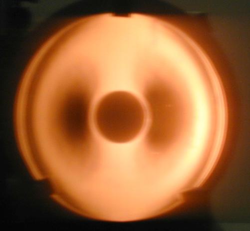
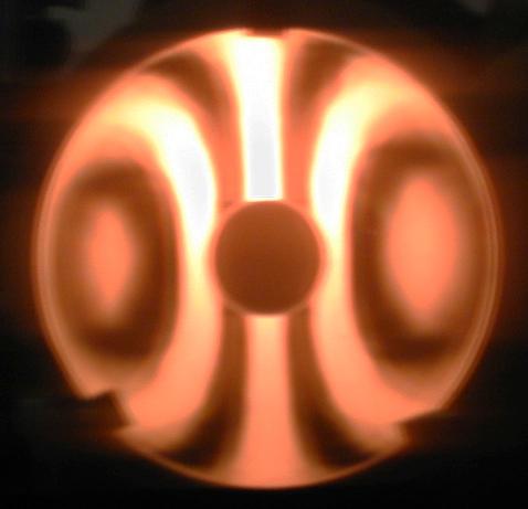
9 Diffraction by a circular aperture as a function of defocus for third-order spherical aberration Page 9


10 Diffraction by a circular aperture in the presence of third-order spherical aberration Paraxial focus Small distance inside paraxial focus Moderate distance from marginal focus Immediate neighborhood of marginal focus Page 10


11 Diffraction by a circular aperture in the presence of third-order coma 6 λ 2.5 λ 1 λ Page 11

12 Diffraction by a circular aperture in the presence of astigmatism 7 λ 1.5 λ 0.23 λ Page 12


13 Diffraction by a circular aperture - astigmatism in the neighborhood of the circle of least confusion 7 λ 1.6 λ 0.23 λ Page 13
14 Star Test - Detecting Chromatic Aberration n In a perfectly apochromatic system a symmetrical white image is obtained for all focal positions. n If chromatic aberration is present the image color is a function of focal position. In moving away from the lens through the paraxial focal plane, a sequence of images is observed. Well away from focus, a white flare is observed. As the blue focus is reached, the color balance is seen to change as blue light appears to be removed from the flare and is concentrated in a core. Farther away from the lens a similar color effect is observed as the foci for green and red are reached. For overcorrected color, the colors appear in the opposite order. Page 14
15 Lateral Chromatic Aberration n The chromatic errors in an off-axis image are most spectacular in visual testing. n The lateral separation of the images in red and blue light gives directly the amount of lateral chromatic aberration. n If the red image is found to lie at a greater distance from the axis than the blue image, negative or undercorrected lateral color is present, while for overcorrected lateral color, the blue image is a greater distance from the axis than the red image. Page 15
16 Shack-Hartmann Test Geometrical ray trace that measures angular, transverse, or longitudinal aberrations from which numerical integration can be used to calculate the wavefront aberration. Classical Hartmann Test Hartmann Screen Photographic Plates #1 #2 Geometric Ray Trace Page 16

17 Hartmann Test of Parabola Outside Position Page 17

18 Hartmann Test of Parabola Inside Position Page 18
19 Shack-Hartmann Lenslet Array Page 19

20 Shack-Hartmann Lenslets Page 20
21 Shack-Hartmann Movie Movie showing results obtained using Shack- Hartmann test to measure atmospheric turbulence. Movie showing stellar speckle image Page 21
22 Shack Hartmann Test - Comments n Air turbulence will average out as long as integration time is long compared to period of turbulence n Holes in Hartmann screen large enough so diffraction does not limit measurement accuracy, but not so large surface errors are averaged out n Test often used for adaptive optics Page 22
23 Foucault Knife-Edge Test Surface to be Tested Slit Source Eye Knife Edge Page 23
24 Ray Picture of Foucault Knife-Edge Test Focus Observed Pattern Knife Edge Knife Edge Knife Edge Page 24
25 Shadows for Third-Order Spherical ΔW = W 040 ( x 2 + y 2 ) 2 + ε z h2 ( x 2 + y 2 ) 2R 2 Boundary of geometrical shadow is given by d = R h ΔW y = 4RW y x ( + y 2 ) ε zhy h R If the knife edge is on the axis, d=0, and the solution is y = 0 x 2 + y 2 = ε z h2 4R 2 W 040 One solution is straight line and second is circle of radius " ε ρ = z h 2 $ # 4R 2 W 040 % ' & 1/2 Page 25


26 Third-Order Spherical Knife-Edge on Optical Axis Knife edge near paraxial focus Knife edge partway between paraxial and marginal focus Knife edge near marginal focus Page 26
27 Knife-Edge Not on Optical Axis A B A Knife-edge ahead of marginal focus B Knife-edge behind of paraxial focus Page 27
28 Shadows for Third-Order Coma ΔW = W 131 y 0 y( x 2 + y 2 ) + ε z h2 ( x 2 + y 2 ) 2R 2 If the knife edge is parallel to the x-axis we get an ellipse d = R h ΔW y = R h W 131y 0 ( x 2 + 3y 2 ) ε zhy R If the knife edge is parallel to the y-axis we get a hyperbola d = R h ΔW x = 2R h W 131 y 0 xy ε z hx R Page 28
29 Knife-Edge Test Pattern Due to Coma Knife edge parallel x-axis Inside paraxial focus At paraxial focus Knife edge parallel y-axis Inside paraxial focus At paraxial focus Page 29
30 Shadows for Third-Order Astigmatism d = R h ΔW y = $ 2R h W 222y ε zh ' & )y % R ( ΔW = W 222 y 2 0 y 2 + ε z h2 ( x 2 + y 2 ) 2R 2 If the KE is parallel to either the x-axis or the y-axis we get d = R h ΔW x = ε zh R x Which are straight lines, so the astigmatic wavefront would be indistinguishable from a spherical wavefront. Put KE at an angle α to the x-axis then d = ε z h R xsin α d = ε y Cos α " or [ ] ε x Sin[ α] [ ] 2R h W 222y ε h z $ # R % 'ycos α & Angle of shadow changes as KE moved along axis [ ] Page 30
31 Knife Edge at Angle e y Knife Edge Along the knife edge ε y = mε x + b [ ] [ ] m = Sin α Cos α Cos[ α] = d b d b α e x Therefore, Sin α ε y = ε x Cos α [ ] [ ] + d Cos[ α] and d = ε y Cos[ α] ε x Sin[ α] Page 31
32 Foucault Knife Edge Test - Comments n Advantage of test is simplicity n Disadvantage is that it is sensitive to slopes, not wavefront, and measures slopes in a single direction with single orientation of KE. n While it is possible to get numbers from the KE test, it is generally used as a qualitative test. n An improvement would be a phase KE with transmits both sides with a phase difference between the two halves of 180 o. The diffraction pattern is symmetric, and the boundary centers are easier to determine. Page 32

33 Density Knife Edge Page 33


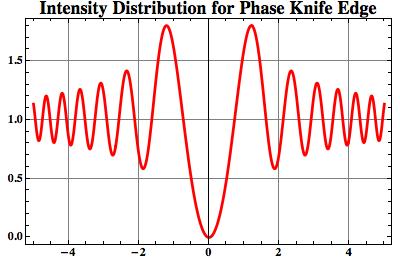
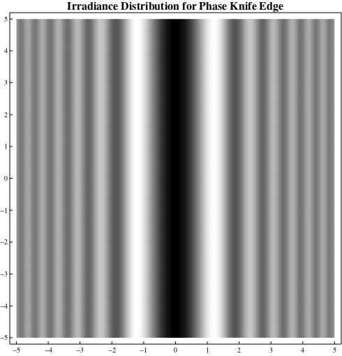
34 Phase Knife Edge Page 34
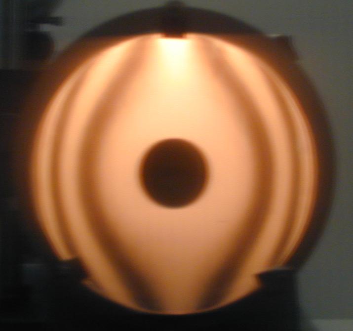
35 Wire Test Same as knife edge test, except knife edge is replaced with a wire. Third-order spherical wire on axis Page 35
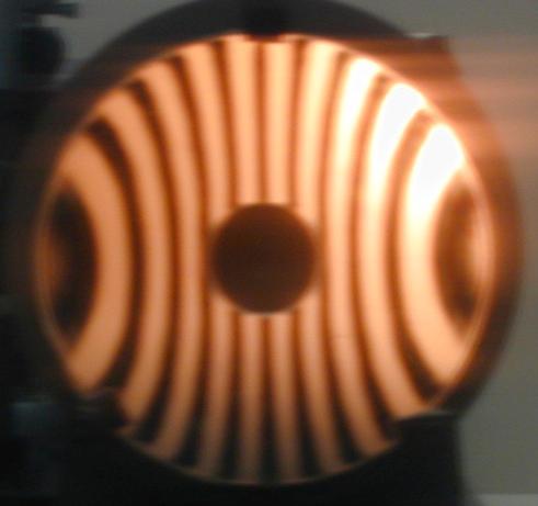
36 Wire Test Third-order spherical, wire off axis Page 36


37 Wire Test Wire test experimental results for parabolic mirror tested at center of curvature Close-up showing diffraction pattern Page 37
38 Wire Test - Comments Wire test better than knife-edge test for quantitative measure, but not as good for qualitative Page 38
39 Ronchi Test A low frequency grating is substituted for knife edge or wire. The test can be understood by considering the Ronchi ruling as equivalent to multiple wires. Convergent Wavefront Eye Ronchi Ruling Page 39

![[ ] + R h ΔW x Sin [ α ] If α = 90](/docs-images/95/123625990/images/40-2.jpg "o, md = R h ΔW x = ε z h R x Page 40")
40 Ronchi Test of Perfect Lens md = ε y Cos[ α] ε x Sin[ α] = R h ΔW y Cos α [ ] + R h ΔW x Sin [ α ] If α = 90 o, md = R h ΔW x = ε z h R x Page 40

41 Ronchi Test Third-Order Spherical Page 41
42 Ronchigrams From the Lab Margy Green, 2002 Page 42

43 Ronchi Test Patterns for Third-Order Coma Page 43

44 Ronchi Test Patterns for Astigmatism Page 44
45 Ronchi Test Using Extended Diffuse Source Surface to be Tested Diffuse Source Eye Ronchi Ruling Page 45
46 Ronchi Test - Comments n The advantages are that the test is simple and will work with a white light source n Disadvantage is that it does not give the wavefront directly, and for a single Ronchi ruling orientation slope in only one direction is obtained n The diffraction effects are very troublesome and limit the accuracy of the test Page 46

47 Created by Margy Green, 2003
48 Lateral Shear Interferometry Measures wavefront slope Shear Plate Source Collimator Lens Interferogram Shear = Δx Page 48
49 Lateral Shear Fringes Δ W ( x, y ) is wavefront being measured Bright fringe obtained when Δ W ( x + Δ x, y ) - Δ W ( x, y ) = m λ ( ) Δ W x, y x Average over shear distance ( Δ x ) = m λ Measures average value of slope over shear distance Page 49

50 Collimation Measurement Page 50

51 Typical Lateral Shear Interferograms Page 51
52 Lateral Shear Interferometer Two-frequency grating placed near focus Two sheared images of exit pupil of system under test Source Lens under test Two diffracted cones of rays at slightly different angles Measures slope of wavefront, not wavefront shape. Page 52

53 Interferogram Obtained using Grating Lateral Shear Interferometer Page 53
54 Rotating Grating LSI (Variable Shear) Page 54

55 Rotating Grating LSI Page 55
 Page")
56 Shearing Interferograms (Different Shear) Page 56
57 Polarization Interferometers Wollaston Prism Savart Plate Page 57
58 Polarization Lateral Shear Interferometer Polarizer at 45 degrees Page 58

59 Convection currents in vicinity of candle flame observed with polarization interferometer Page 59

60 Convection currents in vicinity of candle flame observed with polarization interferometer Page 60

61 Defects of glass plate observed with polarization interferometer Page 61
62 White Light Grating Interferometer +1 orders Red Light Blue Light Source -1 orders Blue Light Red Light Grating Separation between +1 and 1 orders is proportional to the wavelength. Therefore, fringe spacing same for all wavelengths. Midpoint between sources independent of wavelength, so fringe position independent of wavelength Page 62
63 Two-Frequency White Light Grating Interferometer Two-Frequency Grating Source First orders Grating Freq. 1 Grating Freq. 2 Achromatizing Grating, average frequency of twofrequency grating Equivalent system Separation between the first orders of the two gratings is proportional to the wavelength. Therefore, fringe spacing same for all wavelengths. Achromatizing grating must be added to make midpoint between sources independent of wavelength, so fringe position independent of wavelength. Page 63
64 White Light Extended Source Lateral Shearing Interferometer Extended source Coherence Function Periodic source, then periodic coherence function. Period of coherence function proportional to wavelength. Therefore, shear should be proportional to wavelength. Page 64


65 White Light Interferograms Shearing interferogram obtained using tungsten arc source. Shearing interferogram obtained using 60 watt incandescent bulb with Ronchi ruling in front of bulb. Page 65
66 One-Dimensional Analysis of Lateral Shearing Interferograms n It is often sufficient to obtain the wavefront profile for a single scan across an interferogram. n If the shear is sufficiently small a lateral shear interferogram gives the derivative of the wavefront in the direction of shear. For small shears the wavefront difference function can be fit to a polynomial and this polynomial can be integrated to obtain the wavefront. n As the shear becomes larger it is no longer valid to assume the wavefront difference function is equal to the derivative. Page 66
67 One-Dimensional Analysis of Lateral Shearing Interferograms Larger Shear n This approach for analyzing LSIs that is valid for both large and small lateral shear Least-squares fit the wavefront difference function to a polynomial and then set this polynomial equal to the finite difference wavefront difference function. Solve for the polynomial coefficients describing the wavefront in terms of the polynomial coefficients describing the wavefront difference function. Page 67
![Determine Wavefront from Wavefront Difference Function v = ## a[n] x + Δ & %% $ 2 ( ' n=1 $ nmax Wavefront difference function from interferogram n # x Δ & % ( $ 2 '](/docs-images/95/123625990/images/68-1.jpg "wdf = Δw = n & ( ' nmax 1 n=0 nmax n=1 b[n]x n Wavefront can be written as a[n]x n Wavefront difference function can be written as Solve for a s in term of the b s Page")
68 Determine Wavefront from Wavefront Difference Function v = ## a[n] x + Δ & %% $ 2 ( ' n=1 $ nmax Wavefront difference function from interferogram n # x Δ & % ( $ 2 ' wdf = Δw = n & ( ' nmax 1 n=0 nmax n=1 b[n]x n Wavefront can be written as a[n]x n Wavefront difference function can be written as Solve for a s in term of the b s Page 68
69 Solve a s in terms of b s Spherical a[ 4] Coma a[ 4] Defocus a[ 4] Tilt a[ 4] b[3] 4Δ b[2] 3Δ b[1] 2Δ Δb 3 b[0] - Δ [ ] 1 12 Δb 2 [ ] Simple integration would have given only the first term in each expression above. Using the fact that a lateral shearing interferometer involves a finitedifference, rather than a derivative, makes it possible to obtain better results when the shear is not extremely small. Page 69
70 Results Wavefront Difference Function Wavefront Wavefront minus Tilt 4 th Order Portion Page 70
71 Shack Approach for Analyzing LSIs n Wavefront difference function can be thought of as convolving the wavefront with an odd-impulse pair separated the shear distance. n The Fourier transform of a convolution is the product of the two Fourier transforms. n Divide the Fourier transform of the WDF by the FT of the two delta functions (2 i Sin()). n Do an inverse transform to get the wavefront. Ref: Ronald Gruenzel, JOSA, 66, No. 12, 1341 (1976). Page 71
72 Lateral Shear Interferometer - Comments n The advantages are that the test is simple n Disadvantage is that it does not give the wavefront directly, and for a single direction of shear slope in only one direction is obtained Page 72
73 Radial Shear Interferometry Wavefront is interfered with expanded version of itself 2S 1 2S 2 Laser S 1 Radial Shear = R = S 1 S 2 S 2 Page 73
74 Analysis of Radial Shear Interferograms Wavefront being measured ΔW ρ,θ ( ) = W 020 ρ 2 + W 040 ρ 4 + W 131 ρ 3 cosθ + W 222 ρ 2 cos 2 θ Expanded beam can be written ΔW Rρ,θ ( ) = W 020 (Rρ) 2 + W 040 (Rρ) 4 + W 131 (Rρ) 3 cosθ +W 222 (Rρ) 2 cos 2 θ Hence, a bright fringe is obtained whenever ΔW( ρ,θ) ΔW Rρ,θ +W 131 ρ 3 (1 R 3 )cosθ + W 222 ρ 2 (1 R 2 ) cos 2 θ ( ) = W 020 ρ 2 (1 R 2 ) + W 040 ρ 4 (1 R 4 ) Same as Twyman - Green if divide each coefficient by (1- R n ) Page 74
75 Radial Shear Interferometer - Comments n Variable Sensitivity Test Large shear - results same as for Twyman-Green Small shear - Low sensitivity test Page 75
Part 1 - Basic Interferometers for Optical Testing
 Part 1 - Basic Interferometers for Optical Testing Two Beam Interference Fizeau and Twyman-Green interferometers Basic techniques for testing flat and spherical surfaces Mach-Zehnder Zehnder,, Scatterplate
Wavefront Sensing using Polarization Shearing Interferometer. A report on the work done for my Ph.D. J.P.Lancelot
 Wavefront Sensing using Polarization Shearing Interferometer A report on the work done for my Ph.D J.P.Lancelot CONTENTS 1. Introduction 2. Imaging Through Atmospheric turbulence 2.1 The statistics of
AOL Spring Wavefront Sensing. Figure 1: Principle of operation of the Shack-Hartmann wavefront sensor
 AOL Spring Wavefront Sensing The Shack Hartmann Wavefront Sensor system provides accurate, high-speed measurements of the wavefront shape and intensity distribution of beams by analyzing the location and
Optics Optical Testing and Testing Instrumentation Lab
 Optics 513 - Optical Testing and Testing Instrumentation Lab Lab #6 - Interference Microscopes The purpose of this lab is to observe the samples provided using two different interference microscopes --
Introduction to aberrations OPTI518 Lecture 5
 Introduction to aberrations OPTI518 Lecture 5 Second-order terms 1 Second-order terms W H W W H W H W, cos 2 2 000 200 111 020 Piston Change of image location Change of magnification 2 Reference for OPD
PRINCIPLES OF PHYSICAL OPTICS
 PRINCIPLES OF PHYSICAL OPTICS C. A. Bennett University of North Carolina At Asheville WILEY- INTERSCIENCE A JOHN WILEY & SONS, INC., PUBLICATION CONTENTS Preface 1 The Physics of Waves 1 1.1 Introduction
Optical Shop Testing. Second Edition. Edited by DANIEL MALACARA. John Wiley & Sons, Inc. A Wiley-Interscience Publication
 Optical Shop Testing Second Edition Edited by DANIEL MALACARA A Wiley-Interscience Publication John Wiley & Sons, Inc. New York I Chichester I Brisbane I Toronto I Singapore Contents Preface to the Second
Lens Design II. Lecture 1: Aberrations and optimization Herbert Gross. Winter term
 Lens Design II Lecture 1: Aberrations and optimization 18-1-17 Herbert Gross Winter term 18 www.iap.uni-jena.de Preliminary Schedule Lens Design II 18 1 17.1. Aberrations and optimization Repetition 4.1.
Metrology and Sensing
 Metrology and Sensing Lecture 5: Interferometry I 08--6 Herbert Gross Winter term 08 www.iap.uni-jena.de Schedule Optical Metrology and Sensing 08 No Date Subject Detailed Content 6.0. Introduction Introduction,
Astro 500 A500/L-7 1
 Astro 500 1 Telescopes & Optics Outline Defining the telescope & observatory Mounts Foci Optical designs Geometric optics Aberrations Conceptually separate Critical for understanding telescope and instrument
Optics.
 Optics www.optics.rochester.edu/classes/opt100/opt100page.html Course outline Light is a Ray (Geometrical Optics) 1. Nature of light 2. Production and measurement of light 3. Geometrical optics 4. Matrix
Metrology and Sensing
 Metrology and Sensing Lecture 5: Interferometry I 06--09 Herbert Gross Winter term 06 www.iap.uni-jena.de Preliminary Schedule No Date Subject Detailed Content 8.0. Introduction Introduction, optical measurements,
Metrology and Sensing
 Metrology and Sensing Lecture 5: Interferometry I 017-11-16 Herbert Gross Winter term 017 www.iap.uni-jena.de Preliminary Schedule No Date Subject Detailed Content 1 19.10. Introduction Introduction, optical
Nature of Light Part 2
 Nature of Light Part 2 Fresnel Coefficients From Helmholts equation see imaging conditions for Single lens 4F system Diffraction ranges Rayleigh Range Diffraction limited resolution Interference Newton
Polarization Shearing Interferometer (PSI) Based Wavefront Sensor for Adaptive Optics Application. A.K.Saxena and J.P.Lancelot
 Based Wavefront Sensor for Adaptive Optics Application. A.K.Saxena and J.P.Lancelot") Polarization Shearing Interferometer (PSI) Based Wavefront Sensor for Adaptive Optics Application A.K.Saxena and J.P.Lancelot Adaptive Optics A Closed loop Optical system to compensate atmospheric turbulence
Polarization Shearing Interferometer (PSI) Based Wavefront Sensor for Adaptive Optics Application A.K.Saxena and J.P.Lancelot Adaptive Optics A Closed loop Optical system to compensate atmospheric turbulence
The science of light. P. Ewart
 The science of light P. Ewart Oxford Physics: Second Year, Optics Parallel reflecting surfaces t images source Extended source path difference xcos 2t=x Fringes localized at infinity Circular fringe constant
Metrology and Sensing
 Metrology and Sensing Lecture 5: Interferometry I 07--6 Herbert Gross Winter term 07 www.iap.uni-jena.de Preliminary Schedule No Date Subject Detailed Content 9.0. Introduction Introduction, optical measurements,
Astronomy 203 practice final examination
 Astronomy 203 practice final examination Fall 1999 If this were a real, in-class examination, you would be reminded here of the exam rules, which are as follows: You may consult only one page of formulas
Light as Wave Motion p. 1 Huygens' Ideas p. 2 Newton's Ideas p. 8 Complex Numbers p. 10 Simple Harmonic Motion p. 11 Polarized Waves in a Stretched
 Introduction p. xvii Light as Wave Motion p. 1 Huygens' Ideas p. 2 Newton's Ideas p. 8 Complex Numbers p. 10 Simple Harmonic Motion p. 11 Polarized Waves in a Stretched String p. 16 Velocities of Mechanical
Telescopes and Optics II. Observational Astronomy 2017 Part 4 Prof. S.C. Trager
 Telescopes and Optics II Observational Astronomy 2017 Part 4 Prof. S.C. Trager Fermat s principle Optics using Fermat s principle Fermat s principle The path a (light) ray takes is such that the time of
Physical Optics. Lecture 2: Diffraction Herbert Gross.
 Physical Optics Lecture : Diffraction 018-04-18 Herbert Gross www.iap.uni-jena.de Physical Optics: Content No Date Subject Ref Detailed Content 1 11.04. Wave optics G Complex fields, wave equation, k-vectors,
International Journal of Scientific & Engineering Research, Volume 4, Issue 7, July ISSN
 International Journal of Scientific & Engineering Research, Volume 4, Issue 7, July-2013 96 Performance and Evaluation of Interferometric based Wavefront Sensors M.Mohamed Ismail1, M.Mohamed Sathik2 Research
Waves Part III Electromagnetic waves
 Waves Part III Electromagnetic waves Electromagnetic (light) waves Transverse waves Transport energy (and momentum) Can travel through vacuum (!) and certain solids, liquids and gases Do not transport
Probing the orbital angular momentum of light with a multipoint interferometer
 CHAPTER 2 Probing the orbital angular momentum of light with a multipoint interferometer We present an efficient method for probing the orbital angular momentum of optical vortices of arbitrary sizes.
Optical Instruments. Chapter 25. Simple Magnifier. Clicker 1. The Size of a Magnified Image. Angular Magnification 4/12/2011
 Optical Instruments Chapter 25 Optical Instruments Analysis generally involves the laws of reflection and refraction Analysis uses the procedures of geometric optics To explain certain phenomena, the wave
Introduction to Interferometer and Coronagraph Imaging
 Introduction to Interferometer and Coronagraph Imaging Wesley A. Traub NASA Jet Propulsion Laboratory and Harvard-Smithsonian Center for Astrophysics Michelson Summer School on Astrometry Caltech, Pasadena
Optical/IR Observational Astronomy Telescopes I: Optical Principles. David Buckley, SAAO. 24 Feb 2012 NASSP OT1: Telescopes I-1
 David Buckley, SAAO 24 Feb 2012 NASSP OT1: Telescopes I-1 1 What Do Telescopes Do? They collect light They form images of distant objects The images are analyzed by instruments The human eye Photographic
Optical/IR Observational Astronomy Telescopes I: Telescope Basics. David Buckley, SAAO
 David Buckley, SAAO 27 Feb 2012 1 Some other Telescope Parameters 1. Plate Scale This defines the scale of an image at the telescopes focal surface For a focal plane, with no distortion, this is just related
Exam 3--PHYS 202--S10
 ame: Exam 3--PHYS 202--S0 Multiple Choice Identify the choice that best completes the statement or answers the question A person uses a convex lens that has a focal length of 25 cm to inspect a gem The
Design and Correction of optical Systems
 Design and Correction of optical Systems Part 10: Performance criteria 1 Summer term 01 Herbert Gross Overview 1. Basics 01-04-18. Materials 01-04-5 3. Components 01-05-0 4. Paraxial optics 01-05-09 5.
Sky demonstration of potential for ground layer adaptive optics correction
 Sky demonstration of potential for ground layer adaptive optics correction Christoph J. Baranec, Michael Lloyd-Hart, Johanan L. Codona, N. Mark Milton Center for Astronomical Adaptive Optics, Steward Observatory,
5. Aberration Theory
 5. Aberration Theory Last lecture Matrix methods in paraxial optics matrix for a two-lens system, principal planes This lecture Wavefront aberrations Chromatic Aberration Third-order (Seidel) aberration
Astronomy. Optics and Telescopes
 Astronomy A. Dayle Hancock adhancock@wm.edu Small 239 Office hours: MTWR 10-11am Optics and Telescopes - Refraction, lenses and refracting telescopes - Mirrors and reflecting telescopes - Diffraction limit,
Lecture 2: Geometrical Optics 1. Spherical Waves. From Waves to Rays. Lenses. Chromatic Aberrations. Mirrors. Outline
 Lecture 2: Geometrical Optics 1 Outline 1 Spherical Waves 2 From Waves to Rays 3 Lenses 4 Chromatic Aberrations 5 Mirrors Christoph U. Keller, Utrecht University, C.U.Keller@uu.nl Astronomical Telescopes
Optical/IR Observational Astronomy Telescopes I: Telescope Basics. David Buckley, SAAO
 David Buckley, SAAO 17 Feb 2010 1 Some other Telescope Parameters 1. Plate Scale This defines the scale of an image at the telescopes focal surface For a focal plane, with no distortion, this is just related
Laser Speckle and Applications in Optics
 Laser Speckle and Applications in Optics M. FRANCON Optics Laboratory Faculty of Sciences University of Paris Paris, France Translated by HENRI H. ARSENAULT Department of Physics Laval University Quebec,
Fully achromatic nulling interferometer (FANI) for high SNR exoplanet characterization
 for high SNR exoplanet characterization") Fully achromatic nulling interferometer (FANI) for high SNR exoplanet characterization François Hénault Institut de Planétologie et d Astrophysique de Grenoble Université Joseph Fourier Centre National
Fully achromatic nulling interferometer (FANI) for high SNR exoplanet characterization François Hénault Institut de Planétologie et d Astrophysique de Grenoble Université Joseph Fourier Centre National
Chapter 6 Aberrations
 EE90F Chapter 6 Aberrations As we have seen, spherical lenses only obey Gaussian lens law in the paraxial approxiation. Deviations fro this ideal are called aberrations. F Rays toward the edge of the pupil
A Question. Simple Magnifier. Magnification by a Lens 11/29/2011. The last lecture
 The last lecture Exam: Final: Consult the website, especially room assignments. Makeup: Register with me today. Tea and Cookies: Tuesdays 5PM, NPB 2175 A Question Unpolarized light of intensity I goes
Lecture 2: Basic Astronomical Optics. Prisms, Lenses, and Mirrors
 Lecture 2: Basic Astronomical Optics Prisms, Lenses, and Mirrors Basic Optical Elements Refraction (Lenses) No longer used for large telescopes Widely used for instrument optics Reflection (mirrors) Widely
On the diffraction of light by spherical obstacles
 Proc. Phys. Soc. London 38 350-353 (1926) On the diffraction of light by spherical obstacles PROFESSOR C V RAMAN, F.R.S. and Mr K S KRISHNAN ABSTRACT The diffraction of light inside the shadow, thrown
ROTATIONAL SHEARING INTERFEROMATER. Introduction. The Interferometer. L. Yeswanth, Optics Group, IIA, Bangalore
 ROTATIONAL SHEARING INTERFEROMATER L. Yeswanth, Optics Group, IIA, Bangalore Introduction A rotational shearing interferometer is a modification of the Michelson s interferometer to obtain the spatial
Real Telescopes & Cameras. Stephen Eikenberry 05 October 2017
 Lecture 7: Real Telescopes & Cameras Stephen Eikenberry 05 October 2017 Real Telescopes Research observatories no longer build Newtonian or Parabolic telescopes for optical/ir astronomy Aberrations from
THE DIFFRACTION GRATING SPECTROMETER
 Purpose Theory THE DIFFRACTION GRATING SPECTROMETER a. To study diffraction of light using a diffraction grating spectrometer b. To measure the wavelengths of certain lines in the spectrum of the mercury
Downloaded from
 Question 10.1: Monochromatic light of wavelength 589 nm is incident from air on a water surface. What are the wavelength, frequency and speed of (a) reflected, and (b) refracted light? Refractive index
Imaging Metrics. Frequency response Coherent systems Incoherent systems MTF OTF Strehl ratio Other Zemax Metrics. ECE 5616 Curtis
 Imaging Metrics Frequenc response Coherent sstems Incoherent sstems MTF OTF Strehl ratio Other Zema Metrics Where we are going with this Use linear sstems concept of transfer function to characterize sstem
Topic 4 &11 Review Waves & Oscillations
 Name: Date: Topic 4 &11 Review Waves & Oscillations 1. A source produces water waves of frequency 10 Hz. The graph shows the variation with horizontal position of the vertical displacement of the surface
Michelson Interferometer
 Michelson Interferometer Objective Determination of the wave length of the light of the helium-neon laser by means of Michelson interferometer subsectionprinciple and Task Light is made to produce interference
CHARA Meeting 2017 Pasadena, California
 MORE AUTOMATION Laszlo Sturmann M7 ACTUATORS LAB. LASER ALIGNMENT TELESCOPE OPTICAL ALIGNMENT NEW ACTUATORS REMOTELY ACTUATED M7 MOUNT MOTIVATION THE PRECISION OF THE COUDE ALIGNMENT WAS NOT SUFFICIENT
Concave mirrors. Which of the following ray tracings is correct? A: only 1 B: only 2 C: only 3 D: all E: 2& 3
 Concave mirrors Which of the following ray tracings is correct? A: only 1 B: only 2 C: only 3 D: all E: 2& 3 1 2 3 c F Point C: geometrical center of the mirror, F: focal point 2 Concave mirrors Which
solar telescopes Solar Physics course lecture 5 Feb Frans Snik BBL 707
 Solar Physics course lecture 5 Feb 19 2008 Frans Snik BBL 707 f.snik@astro.uu.nl www.astro.uu.nl/~snik solar vs. nighttime telescopes solar constant: 1.37 kw/m 2 destroys optics creates seeing solar vs.
Week 7: Interference
 Week 7: Interference Superposition: Till now we have mostly discusssed single waves. While discussing group velocity we did talk briefly about superposing more than one wave. We will now focus on superposition
Overview of Aberrations
 Overview of Aberrations Lens Design OPTI 57 Aberration From the Latin, aberrare, to wander from; Latin, ab, away, errare, to wander. Symmetry properties Overview of Aberrations (Departures from ideal behavior)
Measurements in Optics for Civil Engineers
 Measurements in Optics for Civil Engineers I. FOCAL LENGTH OF LENSES The behavior of simplest optical devices can be described by the method of geometrical optics. For convex or converging and concave
Phys102 Lecture Diffraction of Light
 Phys102 Lecture 31-33 Diffraction of Light Key Points Diffraction by a Single Slit Diffraction in the Double-Slit Experiment Limits of Resolution Diffraction Grating and Spectroscopy Polarization References
Magnifying Glass. Angular magnification (m): 25 cm/f < m < 25cm/f + 1. image at 25 cm (= normal near point) relaxed eye, image at (normal) far point
: 25 cm/f < m < 25cm/f + 1. image at 25 cm (= normal near point) relaxed eye, image at (normal) far point") Magnifying Glass Angular magnification (m): 25 cm/f < m < 25cm/f + 1 relaxed eye, image at (normal) far point image at 25 cm (= normal near point) For more magnification, first use a lens to form an enlarged
Magnifying Glass Angular magnification (m): 25 cm/f < m < 25cm/f + 1 relaxed eye, image at (normal) far point image at 25 cm (= normal near point) For more magnification, first use a lens to form an enlarged
Einstein Classes, Unit No. 102, 103, Vardhman Ring Road Plaza, Vikas Puri Extn., Outer Ring Road New Delhi , Ph. : ,
 1 O P T I C S 1. Define resolving power of a telescope & microscope and give the expression for its resolving power. 2. Explain briefly the formation of mirage in deserts. 3. The radii of curvature of
Why Use a Telescope?
 1 Why Use a Telescope? All astronomical objects are distant so a telescope is needed to Gather light -- telescopes sometimes referred to as light buckets Resolve detail Magnify an image (least important
Interference, Diffraction and Fourier Theory. ATI 2014 Lecture 02! Keller and Kenworthy
 Interference, Diffraction and Fourier Theory ATI 2014 Lecture 02! Keller and Kenworthy The three major branches of optics Geometrical Optics Light travels as straight rays Physical Optics Light can be
Phys 531 Lecture 27 6 December 2005
 Phys 531 Lecture 27 6 December 2005 Final Review Last time: introduction to quantum field theory Like QM, but field is quantum variable rather than x, p for particle Understand photons, noise, weird quantum
VS203B midterm exam version A
 VS03B midterm exam version A VS03B Midterm Exam Solutions (versions A and B are the same except for the ordering of multiple choice answers Dr. Roorda Date: April 8 009 Permitted aids: pens/pencils, eraser,
Light as a Transverse Wave.
 Waves and Superposition (Keating Chapter 21) The ray model for light (i.e. light travels in straight lines) can be used to explain a lot of phenomena (like basic object and image formation and even aberrations)
Optics and Telescopes
 Optics and Telescopes Guiding Questions 1. Why is it important that telescopes be large? 2. Why do most modern telescopes use a large mirror rather than a large lens? 3. Why are observatories in such remote
1. Consider the biconvex thick lens shown in the figure below, made from transparent material with index n and thickness L.
 Optical Science and Engineering 2013 Advanced Optics Exam Answer all questions. Begin each question on a new blank page. Put your banner ID at the top of each page. Please staple all pages for each individual
1. Waves and Particles 2. Interference of Waves 3. Wave Nature of Light
 1. Waves and Particles 2. Interference of Waves 3. Wave Nature of Light 1. Double-Slit Eperiment reading: Chapter 22 2. Single-Slit Diffraction reading: Chapter 22 3. Diffraction Grating reading: Chapter
10 Lecture, 5 October 1999
 10 Lecture, 5 October 1999 10.1 Aberration compensation for spherical primaries: the Schmidt camera All-reflecting optical systems are called catoptric; all-refracting systems are called dioptric. Mixed
Physics 116. Nov 3, Lecture 21 Wave optics. R. J. Wilkes 11/3/11 1
 Physics 116 Lecture 21 Wave optics Nov 3, 2011 R. J. Wilkes Email: ph116@u.washington.edu 11/3/11 1 Announcements 3 clickers have quiz data logged, but no registration: 622961 649314 614235 If one of these
Astronomical Optics. Second Edition DANIEL J. SCHROEDER ACADEMIC PRESS
 Astronomical Optics Second Edition DANIEL J. SCHROEDER Professor of Physics and Astronomy, Emeritus Department of Physics and Astronomy Beloit College, Beloit, Wisconsin ACADEMIC PRESS A Harcourt Science
PHY410 Optics Exam #3
 PHY410 Optics Exam #3 NAME: 1 2 Multiple Choice Section - 5 pts each 1. A continuous He-Ne laser beam (632.8 nm) is chopped, using a spinning aperture, into 500 nanosecond pulses. Compute the resultant
5. LIGHT MICROSCOPY Abbe s theory of imaging
 5. LIGHT MICROSCOPY. We use Fourier optics to describe coherent image formation, imaging obtained by illuminating the specimen with spatially coherent light. We define resolution, contrast, and phase-sensitive
Design and Correction of Optical Systems
 Design and Correction of Optical Systems Lecture 7: PSF and Optical transfer function 017-05-0 Herbert Gross Summer term 017 www.iap.uni-jena.de Preliminary Schedule - DCS 017 1 07.04. Basics 1.04. Materials
Introduction to aberrations OPTI 518 Lecture 14
 Introduction to aberrations Lecture 14 Topics Structural aberration coefficients Examples Structural coefficients Ж Requires a focal system Afocal systems can be treated with Seidel sums Structural stop
Michelson Interferometer. crucial role in Einstein s development of the Special Theory of Relativity.
 Michelson Interferometer The interferometer Michelson experiment Interferometer of Michelson and Morley played 0 a crucial role in Einstein s development of the Special Theory of Relativity. Michelson
One-Dimensional Analysis of Lateral Shearing Interferograms
 One-Dimensional Analysis of Lateral Shearing Interferograms James C. Wyant Optical Sciences Center University of Arizona Introduction Although techniques have been developed for obtaining the entire wavefront
Recent progress in SR interferometer
 Recent progress in SR interferometer -for small beam size measurement- T. Mitsuhashi, KEK Agenda 1. Brief introduction of beam size measurement through SR interferometry. 2. Theoretical resolution of interferometry
LC circuit: Energy stored. This lecture reviews some but not all of the material that will be on the final exam that covers in Chapters
 Disclaimer: Chapter 29 Alternating-Current Circuits (1) This lecture reviews some but not all of the material that will be on the final exam that covers in Chapters 29-33. LC circuit: Energy stored LC
Lecture 19 Optical MEMS (1)
") EEL6935 Advanced MEMS (Spring 5) Instructor: Dr. Huikai Xie Lecture 19 Optical MEMS (1) Agenda: Optics Review EEL6935 Advanced MEMS 5 H. Xie 3/8/5 1 Optics Review Nature of Light Reflection and Refraction
EEL6935 Advanced MEMS (Spring 5) Instructor: Dr. Huikai Xie Lecture 19 Optical MEMS (1) Agenda: Optics Review EEL6935 Advanced MEMS 5 H. Xie 3/8/5 1 Optics Review Nature of Light Reflection and Refraction
CHEM-E5225 :Electron Microscopy Imaging
 CHEM-E5225 :Electron Microscopy Imaging 2016.10 Yanling Ge Outline Planar Defects Image strain field WBDF microscopy HRTEM information theory Discuss of question homework? Planar Defects - Internal Interface
General Physics II Summer Session 2013 Review Ch - 16, 17, 18
 95.104 General Physics II Summer Session 2013 Review Ch - 16, 17, 18 A metal ball hangs from the ceiling by an insulating thread. The ball is attracted to a positivecharged rod held near the ball. The
The Diffraction Grating
 The Diffraction Grating If one extends the double slit to large number of slits very closely spaced, one gets what is called a diffraction grating. d sin θ. Maxima are still at d sin θ m = mλ, m = 0, 1,
JRE Group of Institutions ASSIGNMENT # 1 Special Theory of Relativity
 ASSIGNMENT # 1 Special Theory of Relativity 1. What was the objective of conducting the Michelson-Morley experiment? Describe the experiment. How is the negative result of the experiment interpreted? 2.
Name Final Exam May 1, 2017
 Name Final Exam May 1, 217 This test consists of five parts. Please note that in parts II through V, you can skip one question of those offered. Some possibly useful formulas appear below. Constants, etc.
Edward S. Rogers Sr. Department of Electrical and Computer Engineering. ECE426F Optical Engineering. Final Exam. Dec. 17, 2003.
 Edward S. Rogers Sr. Department of Electrical and Computer Engineering ECE426F Optical Engineering Final Exam Dec. 17, 2003 Exam Type: D (Close-book + one 2-sided aid sheet + a non-programmable calculator)
Today. MIT 2.71/2.710 Optics 11/10/04 wk10-b-1
 Today Review of spatial filtering with coherent illumination Derivation of the lens law using wave optics Point-spread function of a system with incoherent illumination The Modulation Transfer Function
Astronomy 114. Lecture 26: Telescopes. Martin D. Weinberg. UMass/Astronomy Department
 Astronomy 114 Lecture 26: Telescopes Martin D. Weinberg weinberg@astro.umass.edu UMass/Astronomy Department A114: Lecture 26 17 Apr 2007 Read: Ch. 6,26 Astronomy 114 1/17 Announcements Quiz #2: we re aiming
3.5 Cavities Cavity modes and ABCD-matrix analysis 206 CHAPTER 3. ULTRASHORT SOURCES I - FUNDAMENTALS
 206 CHAPTER 3. ULTRASHORT SOURCES I - FUNDAMENTALS which is a special case of Eq. (3.30. Note that this treatment of dispersion is equivalent to solving the differential equation (1.94 for an incremental
LAB DEMONSTRATION OF INTERFEROMETRIC
 LAB DEMONSTRATION OF INTERFEROMETRIC MEASUREMENT USING A TEST PLATE AND CGH Presented to: Larry Stepp Eric Hansen The Association of Universities for Research in Astronomy, Inc. Tucson, AZ, 85726 Prepared
How Light Beams Behave. Light and Telescopes Guiding Questions. Telescopes A refracting telescope uses a lens to concentrate incoming light at a focus
 Light and Telescopes Guiding Questions 1. Why is it important that telescopes be large? 2. Why do most modern telescopes use a large mirror rather than a large lens? 3. Why are observatories in such remote
* AIT-4: Aberrations. Copyright 2006, Regents of University of California
 Advanced Issues and Technology (AIT) Modules Purpose: Explain the top advanced issues and concepts in optical projection printing and electron-beam lithography. AIT-: LER and Chemically Amplified Resists
Phase Retrieval for the Hubble Space Telescope and other Applications Abstract: Introduction: Theory:
 Phase Retrieval for the Hubble Space Telescope and other Applications Stephanie Barnes College of Optical Sciences, University of Arizona, Tucson, Arizona 85721 sab3@email.arizona.edu Abstract: James R.
SIMG Optics for Imaging Solutions to Final Exam
 SIMG-733-009 Optics for Imaging Solutions to Final Exam. An imaging system consists of two identical thin lenses each with focal length f = f = +300 mm and diameter d = d =50mm. The lenses are separated
High-Resolution. Transmission. Electron Microscopy
 Part 4 High-Resolution Transmission Electron Microscopy 186 Significance high-resolution transmission electron microscopy (HRTEM): resolve object details smaller than 1nm (10 9 m) image the interior of
Physical Principles of Electron Microscopy. 2. Electron Optics
 Physical Principles of Electron Microscopy 2. Electron Optics Ray Egerton University of Alberta and National Institute of Nanotechnology Edmonton, Canada www.tem-eels.ca regerton@ualberta.ca Properties
 Optics. The refractive index of a material of a plain concave lens is 5/3, the radius of curvature is 0.3m. The focal length of the lens in air is ) 0.45 m ) 0.6 m 3) 0.75 m 4).0 m. The refractive index
Alignment aberrations of the New Solar Telescope
 Alignment aberrations of the New Solar Telescope Anastacia M. Manuel and James H. Burge College of Optical Sciences/University of Arizona 1630 East University Blvd., Tucson, AZ 85721, USA ABSTRACT The
ROINN NA FISICE Department of Physics
 ROINN NA FISICE Department of 1.1 Astrophysics Telescopes Profs Gabuzda & Callanan 1.2 Astrophysics Faraday Rotation Prof. Gabuzda 1.3 Laser Spectroscopy Cavity Enhanced Absorption Spectroscopy Prof. Ruth
Observing the Universe. Optical Instruments
 Observing the Universe Optical Instruments Our Eye The fovea has a high concentration of cones sensitive to colour. Other parts of the retina have more rods these are not sensitive to colour, but have
Test 4 Preparation Questions
 Test 4 Preparation Questions A1. One joule of work is required to move a one-coulomb point charge from point A to point B in a uniform electric field. This indicates that (A) the resistance between points
Electricity & Optics
 Physics 24100 Electricity & Optics Lecture 26 Chapter 33 sec. 1-4 Fall 2017 Semester Professor Koltick Interference of Light Interference phenomena are a consequence of the wave-like nature of light Electric
THE MICHELSON INTERFEROMETER Intermediate ( first part) to Advanced (latter parts)
 to Advanced (latter parts)") THE MICHELSON INTERFEROMETER Intermediate ( first part) to Advanced (latter parts) Goal: There is a progression of goals for this experiment but you do not have to do the last goal. The first goal is to
THE MICHELSON INTERFEROMETER Intermediate ( first part) to Advanced (latter parts) Goal: There is a progression of goals for this experiment but you do not have to do the last goal. The first goal is to