Nature of Light Part 2
|
|
|
- Matilda Simon
- 5 years ago
- Views:
Transcription
1 Nature of Light Part 2 Fresnel Coefficients From Helmholts equation see imaging conditions for Single lens 4F system Diffraction ranges Rayleigh Range Diffraction limited resolution Interference Newton s Rings

2 Specular vs diffuse reflections

3 Derivation of Fresnel Coefficients Continuity of E tangential at interface and θ i =θ r gives Isotropic media Continuity of H tangential gives Since E = vb, then ne B this can be written as Using u i = u o and the definition r = nt cosθi μt ni cosθi + μ i ni cosθt μi nt cosθi μ t Similar argument for the other polarization
4 Fresnel Coefficients Amplitude and phase of rays at a boundary
5 Fresnel Coefficients Amplitude and phase of rays at a boundary
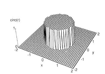
6 Uncoated Glass Reflection Normal Incidence for intensity (square r) R 2 = ((n 2 -n 1 )/(n 1 +n 2 )) 2 Glass is 1.5 to 1.8 index Air is 1 R 2 = (.5/2.5) 2 = 0.04 or 4% Or R 2 = (.8/2.8) 2 = 0.08 or 8% This is why you must use AR coatings on lenses
7 Example of n 1 <n 2 (For real n)

8 Example n 1 >n 2
9 Phase of Reflection Internal Reflection (n t >n i ) External Reflection (n t <n i ) TM TE TE TM

10 Meaning of phase of reflection TE TM

11 Intensity Depends on area and velocity t t t i r i i i i E n n E E n θ θ θ cos cos cos = 2 2 cos cos 1 + = i t i i t t i r E E n n E E θ θ Area of reflected and incident are the same but area of transmitted is different with different angle I i Acosθ i = I r cosθ i + I t Acosθ t Energy flow into an area A must equal energy flowing out of Multiply by c and use expression for intensity results in R =r 2 { T= t 2 { i i t t n n θ θ cos cos T+R=1
12 Plots of R and T
13 Relationship to Fresnel Equation
14 Lens as a thin transparency Positive thin lens transfer function is P(x,y) x Phase Delay (function) of lens Where P(x,y) is the pupil of the lens Lens Function (path length) Positive Lens Into phase paraxial Use definition of f Goodman, Introduction to Fourier Optics
15 Fresnel Diffraction Eq & 1 lens Imaging Impulse response Delta function at (ξ,η) goes to lens After Lens Using Fresnel equation to propagate a distance z 2 Putting it all together. Goodman, Introduction to Fourier Optics
16 Fresnel Diffraction Eq & 1 lens Imaging Impulse response ) Wave imaging condition of getting rid of quadratic phase turns into the Geometrical Optical Imaging condition 1/z 1 +1/z 2-1/f =0 2) Small field curvature and only interested in intensity 3) Object is illuminated with spherical wave, OR small phase change in region of object and contributes to that image point Goodman, Introduction to Fourier Optics
17 Fresnel Diffraction Eq & 1 lens Imaging Impulse response With all these phase factors assumed or hand waved away then can use the definition of M to rewrite remaining terms. M = -z 2 /z 1, magnification of image So, with imaging condition, the impulse response is the scaled FT of the lens aperture centered on coordinates u= Mξ, v=mη While these approximations work reasonably well under typical conditions This does not typically allow for these imaging systems to be cascaded. Goodman, Introduction to Fourier Optics
18 Fourier Transform using Lens Amplitude distribution behind the lens U t (x,y) Plug into Fresnel equation and set z=f to find field at back focal plane Plug in U (x,y) and notice that quadratic phase factor cancels leaving FT with small field curvature (Petzal field curvature) Notice f x = u/λf Goodman, Introduction to Fourier Optics
19 Definitions
20 FT Example Thin sinusoidal amplitude grating FT of the 2 parts separately Then use convolution theory (fortunately easy with delta functions) Goodman, Introduction to Fourier Optics
21 FT Example Thin sinusoidal amplitude grating Fraunhofer Diffraction Pattern Goodman, Introduction to Fourier Optics
22 Question Spatial frequency of pattern is 1000 lp/mm in x direction and is Fourier Transformed by lens of F=10mm and wavelength of 1 um. Where does this spatial frequency end up on the Fourier plane? f x = u/λf rewritten as u = f x λf = 1000(10-3 )(10mm) u = 10mm Lens diameter would have to be larger very fast lens! Draw picture
23 4F Lens System U(x,y) FT(U(x,y) U (-x,-y) f 1 f 1 f 2 f 2 Images with out phase terms true image. These systems can be cascaded. Magnification is ratio of focal lengths M=f 2 /f 1 Filtering or correlations can be done in FT plane Shortest track length imaging system
24 Phase Contrast Viewing How to see phase only object? U(x) FT(U(x)) U (-x) f 1 f 1 f f 2 2 Phase Object U(x) = e iϕ(x) If phase is small ( ϕ(x) 2 <<1) then object can be written as U(x) =1+iϕ(x) At FT plane this is approximately U(ξ) = δ(ξ) +iϕ ~ (x) Now in order to see something in intensity we must filter this try M(x) = e iπ/2 if x <ε, for ε small M(x) = 1 if x >ε With this multiplied into U() and then FT again, the intensity becomes U (x) 2 = 1 +ϕ(x) 2 ~ 1+2 ϕ(x) Phase is visible on camera!!! Reynolds, et al Physical Optics Notebook: Tutorials in Fourier Optics
25 Fourier Optics in 1 Equation
26 Propagation and Diffraction Regions of Diffraction Rayleigh Range near field, far field boundary
27 Diffraction vs propagation distance
28 First Imaging Limitation Spatial Frequencies beyond TIR do not propagate and result in a band limited image with propagation. For example a 1D rect function.
29 Near Field/ Far Field Boundary

30 Near Field/ Far Field Boundary

31 Diffraction Limited Resolution

32 Linear Resolution of Points Sparrow Criterion Note: this is for points, not lines Rayleigh Criterion Rayleigh criterion for resolution is points separated by distance: Δx = 0.61λ nsinθ max 0.61λ = = 1.22λ( F /#) NA Depends on wavelength and largest angle of system (angular bandwidth)
33 Angular Resolution For telescopes or object in distance α = 1.22 w λ Where α is in radians and w is the DIAMETER of the circular aperture Notice for angular resolution the wavelength and the diameter are the key parameters. Note that the focal length does not directly determine the angular resolution.
34 Questions for the day t < d 2 /λ - Rayleight range for direct transmission t < (λ/10) 2 /λ = λ/100 d/10 t < d/10 answer is D


35 Interference Combined Wavefront Wave 1 Wave 2 InPhase out of phase Visibility = I max -I min /(I max +I min )
36 Interference pattern DC terms Interference terms S R I (intensity) 1 hologram index modulation m Modulation depth: m = 2 I m = 1 when beam ratio is 1:1 DC component of illumination wasted media dynamic range R I R I + I S S
37 Interference pattern θ S θ R I (intensity) 1 hologram index modulation m Spatial frequency of this pattern is f x = 2 sinθ/λ
38 Interference Example Newton s Rings Newton's rings is an interference pattern caused by the reflection of light between a spherical surface and an adjacent flat surface. When viewed with monochromatic light it appears as a series of concentric, alternating light and dark rings centered at the point of contact between the two surfaces. When viewed with white light, it forms a concentric ring pattern of rainbow colors because the different wavelengths of light interfere at different thicknesses of the air layer between the surfaces. The light rings are caused by constructive interference between the light rays reflected from both surfaces, while the dark rings are caused by destructive interference. Also, the outer rings are spaced more closely than the inner ones. Moving outwards from one dark ring to the next, for example, increases the path difference by the same amount λ, corresponding to the same increase of thickness of the air layer λ/2. Since the slope of the lens surface increases outwards, separation of the rings gets smaller for the outer rings. Wikipedia

39 Interference Example Newton s Rings The radius of the Nth Newton's bright ring is given by r n = ((N-1/2)λR) 1/2 where N is the bright ring number, R is the radius of curvature of the lens the light is passing through, and λ is the wavelength of the light passing through the glass. Wikipedia
40 Homework Available at the website under homework Due in 2 weeks
Chapter 6 SCALAR DIFFRACTION THEORY
 Chapter 6 SCALAR DIFFRACTION THEORY [Reading assignment: Hect 0..4-0..6,0..8,.3.3] Scalar Electromagnetic theory: monochromatic wave P : position t : time : optical frequency u(p, t) represents the E or
Optics.
 Optics www.optics.rochester.edu/classes/opt100/opt100page.html Course outline Light is a Ray (Geometrical Optics) 1. Nature of light 2. Production and measurement of light 3. Geometrical optics 4. Matrix
Chapter 5 Wave-Optics Analysis of Coherent Optical Systems
 Chapter 5 Wave-Optics Analysis of Coherent Optical Systems January 5, 2016 Chapter 5 Wave-Optics Analysis of Coherent Optical Systems Contents: 5.1 A thin lens as a phase transformation 5.2 Fourier transforming
Fourier Optics - Exam #1 Review
 Fourier Optics - Exam #1 Review Ch. 2 2-D Linear Systems A. Fourier Transforms, theorems. - handout --> your note sheet B. Linear Systems C. Applications of above - sampled data and the DFT (supplement
31. Diffraction: a few important illustrations
 31. Diffraction: a few important illustrations Babinet s Principle Diffraction gratings X-ray diffraction: Bragg scattering and crystal structures A lens transforms a Fresnel diffraction problem into a
LC circuit: Energy stored. This lecture reviews some but not all of the material that will be on the final exam that covers in Chapters
 Disclaimer: Chapter 29 Alternating-Current Circuits (1) This lecture reviews some but not all of the material that will be on the final exam that covers in Chapters 29-33. LC circuit: Energy stored LC
Light Propagation in Free Space
 Intro Light Propagation in Free Space Helmholtz Equation 1-D Propagation Plane waves Plane wave propagation Light Propagation in Free Space 3-D Propagation Spherical Waves Huygen s Principle Each point
MIT 2.71/2.710 Optics 10/31/05 wk9-a-1. The spatial frequency domain
 10/31/05 wk9-a-1 The spatial frequency domain Recall: plane wave propagation x path delay increases linearly with x λ z=0 θ E 0 x exp i2π sinθ + λ z i2π cosθ λ z plane of observation 10/31/05 wk9-a-2 Spatial
Interference, Diffraction and Fourier Theory. ATI 2014 Lecture 02! Keller and Kenworthy
 Interference, Diffraction and Fourier Theory ATI 2014 Lecture 02! Keller and Kenworthy The three major branches of optics Geometrical Optics Light travels as straight rays Physical Optics Light can be
5. LIGHT MICROSCOPY Abbe s theory of imaging
 5. LIGHT MICROSCOPY. We use Fourier optics to describe coherent image formation, imaging obtained by illuminating the specimen with spatially coherent light. We define resolution, contrast, and phase-sensitive
Today in Physics 218: stratified linear media II
 Today in Physics 28: stratified linear media II Characteristic matrix formulation of reflected and transmitted fields and intensity Examples: Single interface Plane-parallel dielectric in vacuum Multiple
High-Resolution. Transmission. Electron Microscopy
 Part 4 High-Resolution Transmission Electron Microscopy 186 Significance high-resolution transmission electron microscopy (HRTEM): resolve object details smaller than 1nm (10 9 m) image the interior of
n The visual examination of the image of a point source is one of the most basic and important tests that can be performed.
 8.2.11 Star Test n The visual examination of the image of a point source is one of the most basic and important tests that can be performed. Interpretation of the image is to a large degree a matter of
SIMG Optics for Imaging Solutions to Final Exam
 SIMG-733-009 Optics for Imaging Solutions to Final Exam. An imaging system consists of two identical thin lenses each with focal length f = f = +300 mm and diameter d = d =50mm. The lenses are separated
Wigner distribution function of volume holograms
 Wigner distribution function of volume holograms The MIT Faculty has made this article openly available. Please share how this access benefits you. Your story matters. Citation As Published Publisher S.
2.71. Final examination. 3 hours (9am 12 noon) Total pages: 7 (seven) PLEASE DO NOT TURN OVER UNTIL EXAM STARTS PLEASE RETURN THIS BOOKLET
 Total pages: 7 (seven) PLEASE DO NOT TURN OVER UNTIL EXAM STARTS PLEASE RETURN THIS BOOKLET") 2.71 Final examination 3 hours (9am 12 noon) Total pages: 7 (seven) PLEASE DO NOT TURN OVER UNTIL EXAM STARTS Name: PLEASE RETURN THIS BOOKLET WITH YOUR SOLUTION SHEET(S) MASSACHUSETTS INSTITUTE OF TECHNOLOGY
2.71 Final examination 3 hours (9am 12 noon) Total pages: 7 (seven) PLEASE DO NOT TURN OVER UNTIL EXAM STARTS Name: PLEASE RETURN THIS BOOKLET WITH YOUR SOLUTION SHEET(S) MASSACHUSETTS INSTITUTE OF TECHNOLOGY
Engineering Physics 1 Prof. G.D. Vermaa Department of Physics Indian Institute of Technology-Roorkee
 Engineering Physics 1 Prof. G.D. Vermaa Department of Physics Indian Institute of Technology-Roorkee Module-04 Lecture-02 Diffraction Part - 02 In the previous lecture I discussed single slit and double
PH880 Topics in Physics
 PH880 Topics in Physics Modern Optical Imaging (Fall 2010) Monday Fourier Optics Overview of week 3 Transmission function, Diffraction 4f telescopic system PSF, OTF Wednesday Conjugate Plane Bih Bright
If the wavelength is larger than the aperture, the wave will spread out at a large angle. [Picture P445] . Distance l S
![If the wavelength is larger than the aperture, the wave will spread out at a large angle. [Picture P445] . Distance l S](/thumbs/77/76053670.jpg "If the wavelength is larger than the aperture, the wave will spread out at a large angle. [Picture P445] . Distance l S") Chapter 10 Diffraction 10.1 Preliminary Considerations Diffraction is a deviation of light from rectilinear propagation. t occurs whenever a portion of a wavefront is obstructed. Hecht; 11/8/010; 10-1
Chapter 10 Diffraction 10.1 Preliminary Considerations Diffraction is a deviation of light from rectilinear propagation. t occurs whenever a portion of a wavefront is obstructed. Hecht; 11/8/010; 10-1
Optical Instruments. Chapter 25. Simple Magnifier. Clicker 1. The Size of a Magnified Image. Angular Magnification 4/12/2011
 Optical Instruments Chapter 25 Optical Instruments Analysis generally involves the laws of reflection and refraction Analysis uses the procedures of geometric optics To explain certain phenomena, the wave
Today. MIT 2.71/2.710 Optics 11/10/04 wk10-b-1
 Today Review of spatial filtering with coherent illumination Derivation of the lens law using wave optics Point-spread function of a system with incoherent illumination The Modulation Transfer Function
General Physics II Summer Session 2013 Review Ch - 16, 17, 18
 95.104 General Physics II Summer Session 2013 Review Ch - 16, 17, 18 A metal ball hangs from the ceiling by an insulating thread. The ball is attracted to a positivecharged rod held near the ball. The
UNIT-5 EM WAVES UNIT-6 RAY OPTICS
 UNIT-5 EM WAVES 2 Marks Question 1. To which regions of electromagnetic spectrum do the following wavelengths belong: (a) 250 nm (b) 1500 nm 2. State any one property which is common to all electromagnetic
Einstein Classes, Unit No. 102, 103, Vardhman Ring Road Plaza, Vikas Puri Extn., Outer Ring Road New Delhi , Ph. : ,
 1 O P T I C S 1. Define resolving power of a telescope & microscope and give the expression for its resolving power. 2. Explain briefly the formation of mirage in deserts. 3. The radii of curvature of
PRINCIPLES OF PHYSICAL OPTICS
 PRINCIPLES OF PHYSICAL OPTICS C. A. Bennett University of North Carolina At Asheville WILEY- INTERSCIENCE A JOHN WILEY & SONS, INC., PUBLICATION CONTENTS Preface 1 The Physics of Waves 1 1.1 Introduction
2.710 Optics Spring 09 Solutions to Problem Set #6 Due Wednesday, Apr. 15, 2009
 MASSACHUSETTS INSTITUTE OF TECHNOLOGY.710 Optics Spring 09 Solutions to Problem Set #6 Due Wednesday, Apr. 15, 009 Problem 1: Grating with tilted plane wave illumination 1. a) In this problem, one dimensional
Chapter 7. Interference of Light
 Chapter 7. Interference of Light Last Lecture Superposition of waves Laser This Lecture Two-Beam Interference Young s Double Slit Experiment Virtual Sources Newton s Rings Film Thickness Measurement by
Week 7: Interference
 Week 7: Interference Superposition: Till now we have mostly discusssed single waves. While discussing group velocity we did talk briefly about superposing more than one wave. We will now focus on superposition
1. Waves and Particles 2. Interference of Waves 3. Wave Nature of Light
 1. Waves and Particles 2. Interference of Waves 3. Wave Nature of Light 1. Double-Slit Eperiment reading: Chapter 22 2. Single-Slit Diffraction reading: Chapter 22 3. Diffraction Grating reading: Chapter
Moonbows. Friday somebody asked if rainbows can be seen at night.
 Moonbows Friday somebody asked if rainbows can be seen at night. Neil Alberding (SFU Physics) Physics 121: Optics, Electricity & Magnetism Spring 2010 1 / 25 Moonbows Friday somebody asked if rainbows
Lecture 4: Diffraction & Spectroscopy
 Lecture 4: Diffraction & Spectroscopy d θ y L Spectra of atoms reveal the quantum nature of matter Take a plastic grating from the bin as you enter class. Lecture 4, p 1 Today s Topics Single-Slit Diffraction*
Phys 531 Lecture 27 6 December 2005
 Phys 531 Lecture 27 6 December 2005 Final Review Last time: introduction to quantum field theory Like QM, but field is quantum variable rather than x, p for particle Understand photons, noise, weird quantum
Physics I : Oscillations and Waves Prof. S. Bharadwaj Department of Physics and Meteorology Indian Institute of Technology, Kharagpur
 Physics I : Oscillations and Waves Prof. S. Bharadwaj Department of Physics and Meteorology Indian Institute of Technology, Kharagpur Lecture - 21 Diffraction-II Good morning. In the last class, we had
1. In Young s double slit experiment, when the illumination is white light, the higherorder fringes are in color.
 TRUE-FALSE STATEMENTS: ELECTRICITY: 1. Electric field lines originate on negative charges. 2. The flux of the electric field over a closed surface is proportional to the net charge enclosed by the surface.
AOL Spring Wavefront Sensing. Figure 1: Principle of operation of the Shack-Hartmann wavefront sensor
 AOL Spring Wavefront Sensing The Shack Hartmann Wavefront Sensor system provides accurate, high-speed measurements of the wavefront shape and intensity distribution of beams by analyzing the location and
A Question. Simple Magnifier. Magnification by a Lens 11/29/2011. The last lecture
 The last lecture Exam: Final: Consult the website, especially room assignments. Makeup: Register with me today. Tea and Cookies: Tuesdays 5PM, NPB 2175 A Question Unpolarized light of intensity I goes
Waves Part III Electromagnetic waves
 Waves Part III Electromagnetic waves Electromagnetic (light) waves Transverse waves Transport energy (and momentum) Can travel through vacuum (!) and certain solids, liquids and gases Do not transport
Exam 4 Solutions. a. 1,2,and 3 b. 1 and 2, not 3 c. 1 and 3, not 2 d. 2 and 3, not 1 e. only 2
 Prof. Darin Acosta Prof. Greg Stewart April 8, 007 1. Which of the following statements is true? 1. In equilibrium all of any excess charge stored on a conductor is on the outer surface.. In equilibrium
Introduction to Interferometer and Coronagraph Imaging
 Introduction to Interferometer and Coronagraph Imaging Wesley A. Traub NASA Jet Propulsion Laboratory and Harvard-Smithsonian Center for Astrophysics Michelson Summer School on Astrometry Caltech, Pasadena
Astronomy 203 practice final examination
 Astronomy 203 practice final examination Fall 1999 If this were a real, in-class examination, you would be reminded here of the exam rules, which are as follows: You may consult only one page of formulas
PHY410 Optics Exam #3
 PHY410 Optics Exam #3 NAME: 1 2 Multiple Choice Section - 5 pts each 1. A continuous He-Ne laser beam (632.8 nm) is chopped, using a spinning aperture, into 500 nanosecond pulses. Compute the resultant
Vector diffraction theory of refraction of light by a spherical surface
 S. Guha and G. D. Gillen Vol. 4, No. 1/January 007/J. Opt. Soc. Am. B 1 Vector diffraction theory of refraction of light by a spherical surface Shekhar Guha and Glen D. Gillen* Materials and Manufacturing
Optical/IR Observational Astronomy Telescopes I: Telescope Basics. David Buckley, SAAO
 David Buckley, SAAO 17 Feb 2010 1 Some other Telescope Parameters 1. Plate Scale This defines the scale of an image at the telescopes focal surface For a focal plane, with no distortion, this is just related
DIFFRACTION AND FOURIER OPTICS I.
 DIFFRACTION AND FOURIER OPTICS I. Introduction Let us examine some of the main features of the Huygens-Fresnel scalar theory of optical diffraction. This theory approximates the vector electric and magnetic
Chapter 10. Interference of Light
 Chapter 10. Interference of Light Last Lecture Wave equations Maxwell equations and EM waves Superposition of waves This Lecture Two-Beam Interference Young s Double Slit Experiment Virtual Sources Newton
Lecture 2: Basic Astronomical Optics. Prisms, Lenses, and Mirrors
 Lecture 2: Basic Astronomical Optics Prisms, Lenses, and Mirrors Basic Optical Elements Refraction (Lenses) No longer used for large telescopes Widely used for instrument optics Reflection (mirrors) Widely
Physics 142 Wave Optics 1 Page 1. Wave Optics 1. For every complex problem there is one solution that is simple, neat, and wrong. H.L.
 Physics 142 Wave Optics 1 Page 1 Wave Optics 1 For every complex problem there is one solution that is simple, neat, and wrong. H.L. Mencken Interference and diffraction of waves The essential characteristic
Version 087 EX4 ditmire (58335) 1
 1") Version 087 EX4 ditmire (58335) This print-out should have 3 questions. Multiple-choice questions ma continue on the next column or page find all choices before answering. 00 (part of ) 0.0 points A material
Version 087 EX4 ditmire (58335) This print-out should have 3 questions. Multiple-choice questions ma continue on the next column or page find all choices before answering. 00 (part of ) 0.0 points A material
A refl = R A inc, A trans = T A inc.
 Reading: Wave Optics 1, 2 Key concepts: Superposition; phase difference; amplitude and intensity; thin film interference; Fraunhofer diffraction; gratings; resolving power. 1.! Questions about interference
Phys102 Lecture Diffraction of Light
 Phys102 Lecture 31-33 Diffraction of Light Key Points Diffraction by a Single Slit Diffraction in the Double-Slit Experiment Limits of Resolution Diffraction Grating and Spectroscopy Polarization References
Properties of waves. Question. Ch 22, : Waves & interference. Question. Phase difference & interference
 Exam Tue. Sep. 9, 5:30-7 pm, 45 Birge Covers.5-7,, 3.-4, 3.7, 4.-5, 6 + lecture, lab, discussion, HW Chap.5-7, Waves, interference, and diffraction Chap 3 Reflection, refraction, and image formation Chap
Electromagnetic fields and waves
 Electromagnetic fields and waves Maxwell s rainbow Outline Maxwell s equations Plane waves Pulses and group velocity Polarization of light Transmission and reflection at an interface Macroscopic Maxwell
EM waves and interference. Review of EM wave equation and plane waves Energy and intensity in EM waves Interference
 EM waves and interference Review of EM wave equation and plane waves Energy and intensity in EM waves Interference Maxwell's Equations to wave eqn The induced polarization, P, contains the effect of the
Optical/IR Observational Astronomy Telescopes I: Telescope Basics. David Buckley, SAAO
 David Buckley, SAAO 27 Feb 2012 1 Some other Telescope Parameters 1. Plate Scale This defines the scale of an image at the telescopes focal surface For a focal plane, with no distortion, this is just related
Modeling microlenses by use of vectorial field rays and diffraction integrals
 Modeling microlenses by use of vectorial field rays and diffraction integrals Miguel A. Alvarez-Cabanillas, Fang Xu, and Yeshaiahu Fainman A nonparaxial vector-field method is used to describe the behavior
Electricity & Optics
 Physics 24100 Electricity & Optics Lecture 26 Chapter 33 sec. 1-4 Fall 2017 Semester Professor Koltick Interference of Light Interference phenomena are a consequence of the wave-like nature of light Electric
Laser Speckle and Applications in Optics
 Laser Speckle and Applications in Optics M. FRANCON Optics Laboratory Faculty of Sciences University of Paris Paris, France Translated by HENRI H. ARSENAULT Department of Physics Laval University Quebec,
Edward S. Rogers Sr. Department of Electrical and Computer Engineering. ECE426F Optical Engineering. Final Exam. Dec. 17, 2003.
 Edward S. Rogers Sr. Department of Electrical and Computer Engineering ECE426F Optical Engineering Final Exam Dec. 17, 2003 Exam Type: D (Close-book + one 2-sided aid sheet + a non-programmable calculator)
Downloaded from
 Question 10.1: Monochromatic light of wavelength 589 nm is incident from air on a water surface. What are the wavelength, frequency and speed of (a) reflected, and (b) refracted light? Refractive index
sin constructive n same condition destructive 2 Interference Constructive - Destructive 2-slit single slit diff. grating
 Interference Constructive - Destructive 2-slit single slit diff. grating reflection Note: difference = 0 difference destructive 2 d sin reflection constructive d 2 sin tot. inter. = reflection + path length
1. Consider the biconvex thick lens shown in the figure below, made from transparent material with index n and thickness L.
 Optical Science and Engineering 2013 Advanced Optics Exam Answer all questions. Begin each question on a new blank page. Put your banner ID at the top of each page. Please staple all pages for each individual
Lecture notes 5: Diffraction
 Lecture notes 5: Diffraction Let us now consider how light reacts to being confined to a given aperture. The resolution of an aperture is restricted due to the wave nature of light: as light passes through
Fourier transform = F. Introduction to Fourier Optics, J. Goodman Fundamentals of Photonics, B. Saleh &M. Teich. x y x y x y
 Fourier transform Introduction to Fourier Optics, J. Goodman Fundamentals of Photonics, B. Saleh &M. Teich f( x, y) FT g( f, f ) f( x, y) IFT g( f, f ) x x y y + 1 { g( f, ) } x fy { π } f( x, y) = g(
Lecture 19 Optical MEMS (1)
") EEL6935 Advanced MEMS (Spring 5) Instructor: Dr. Huikai Xie Lecture 19 Optical MEMS (1) Agenda: Optics Review EEL6935 Advanced MEMS 5 H. Xie 3/8/5 1 Optics Review Nature of Light Reflection and Refraction
EEL6935 Advanced MEMS (Spring 5) Instructor: Dr. Huikai Xie Lecture 19 Optical MEMS (1) Agenda: Optics Review EEL6935 Advanced MEMS 5 H. Xie 3/8/5 1 Optics Review Nature of Light Reflection and Refraction
The spatial frequency domain
 The spatial frequenc /3/5 wk9-a- Recall: plane wave propagation λ z= θ path dela increases linearl with E ep i2π sinθ + λ z i2π cosθ λ z plane of observation /3/5 wk9-a-2 Spatial frequenc angle of propagation?
JRE Group of Institutions ASSIGNMENT # 1 Special Theory of Relativity
 ASSIGNMENT # 1 Special Theory of Relativity 1. What was the objective of conducting the Michelson-Morley experiment? Describe the experiment. How is the negative result of the experiment interpreted? 2.
Chapter 35. Interference
 Chapter 35 Interference The concept of optical interference is critical to understanding many natural phenomena, ranging from color shifting in butterfly wings to intensity patterns formed by small apertures.
Fourier transform = F. Introduction to Fourier Optics, J. Goodman Fundamentals of Photonics, B. Saleh &M. Teich. x y x y x y
 Fourier transform Introduction to Fourier Optics, J. Goodman Fundamentals of Photonics, B. Saleh &M. Teich f( x, y) FT g( f, f ) f( x, y) IFT g( f, f ) x x y y + 1 { g( f, ) } x fy { π } f( x, y) = g(
Introduction to aberrations OPTI518 Lecture 5
 Introduction to aberrations OPTI518 Lecture 5 Second-order terms 1 Second-order terms W H W W H W H W, cos 2 2 000 200 111 020 Piston Change of image location Change of magnification 2 Reference for OPD
Optics Optical Testing and Testing Instrumentation Lab
 Optics 513 - Optical Testing and Testing Instrumentation Lab Lab #6 - Interference Microscopes The purpose of this lab is to observe the samples provided using two different interference microscopes --
Optical Systems Program of Studies Version 1.0 April 2012
 Optical Systems Program of Studies Version 1.0 April 2012 Standard1 Essential Understand Optical experimental methodology, data analysis, interpretation, and presentation strategies Essential Understandings:
Lecture 9: Indirect Imaging 2. Two-Element Interferometer. Van Cittert-Zernike Theorem. Aperture Synthesis Imaging. Outline
 Lecture 9: Indirect Imaging 2 Outline 1 Two-Element Interferometer 2 Van Cittert-Zernike Theorem 3 Aperture Synthesis Imaging Cygnus A at 6 cm Image courtesy of NRAO/AUI Very Large Array (VLA), New Mexico,
Fractional order Fourier transform as a tool for analyzing multi-element optical system
 Fractional order Fourier transform as a tool for analyzing multi-element optical system César O. Torres M. Universidad Popular del Cesar Laboratorio de Optica e Informática, Valledupar, Colombia. torres.cesar@caramail.com
Laser Optics-II. ME 677: Laser Material Processing Instructor: Ramesh Singh 1
 Laser Optics-II 1 Outline Absorption Modes Irradiance Reflectivity/Absorption Absorption coefficient will vary with the same effects as the reflectivity For opaque materials: reflectivity = 1 - absorptivity
Chapter 16 Holography
 Chapter 16 Holography Virtually all recording devices for light respond to light intensity. Problem: How to record, and then later reconstruct both the amplitude and phase of an optical wave. [This question
MANIPAL INSTITUTE OF TECHNOLOGY
 SCHEME OF EVAUATION MANIPA INSTITUTE OF TECHNOOGY MANIPA UNIVERSITY, MANIPA SECOND SEMESTER B.Tech. END-SEMESTER EXAMINATION - MAY SUBJECT: ENGINEERING PHYSICS (PHY/) Time: 3 Hrs. Max. Marks: 5 Note: Answer
DIFFRACTION GRATING. OBJECTIVE: To use the diffraction grating in the formation of spectra and in the measurement of wavelengths.
 DIFFRACTION GRATING OBJECTIVE: To use the diffraction grating in the formation of spectra and in the measurement of wavelengths. THEORY: The operation of the grating is depicted in Fig. 1 on page Lens
Plane waves and spatial frequency. A plane wave
 Plane waves and spatial frequency A plane wave Complex representation E(,) z t = E cos( ωt kz) = E cos( ωt kz) o Ezt (,) = Ee = Ee j( ωt kz) j( ωt kz) o = 1 2 A B t + + + [ cos(2 ω α β ) cos( α β )] {
ROINN NA FISICE Department of Physics
 ROINN NA FISICE Department of 1.1 Astrophysics Telescopes Profs Gabuzda & Callanan 1.2 Astrophysics Faraday Rotation Prof. Gabuzda 1.3 Laser Spectroscopy Cavity Enhanced Absorption Spectroscopy Prof. Ruth
Lecture 16 February 25, 2016
 MTH 262/CME 372: pplied Fourier nalysis and Winter 2016 Elements of Modern Signal Processing Lecture 16 February 25, 2016 Prof. Emmanuel Candes Scribe: Carlos. Sing-Long, Edited by E. Bates 1 Outline genda:
OPSE FINAL EXAM Fall 2016 YOU MUST SHOW YOUR WORK. ANSWERS THAT ARE NOT JUSTIFIED WILL BE GIVEN ZERO CREDIT.
 CLOSED BOOK. Equation Sheet is provided. YOU MUST SHOW YOUR WORK. ANSWERS THAT ARE NOT JUSTIFIED WILL BE GIVEN ZERO CREDIT. ALL NUMERICAL ANSERS MUST HAVE UNITS INDICATED. (Except dimensionless units like
Part 1 - Basic Interferometers for Optical Testing
 Part 1 - Basic Interferometers for Optical Testing Two Beam Interference Fizeau and Twyman-Green interferometers Basic techniques for testing flat and spherical surfaces Mach-Zehnder Zehnder,, Scatterplate
Interference- Michelson Interferometer. Interference lecture by Dr. T.Vishwam
 Interference- Michelson Interferometer Interference lecture by Dr. T.Vishwam * Measurement of the coherence length of a spectral line * Measurement of thickness of thin transparent flakes * Measurement
Physics General Physics II. Electricity, Magnetism and Optics Lecture 20 Chapter Wave Optics. Fall 2015 Semester Prof.
 Physics 21900 General Physics II Electricity, Magnetism and Optics Lecture 20 Chapter 23.1-2 Wave Optics Fall 2015 Semester Prof. Matthew Jones Announcement Exam #2 will be on Thursday, November 5 th (tomorrow)
COMPUTER GENERATED HOLOGRAMS Optical Sciences 627 W.J. Dallas (Monday, August 23, 2004, 12:14 PM)
") COMPUTER GENERATED HOLOGRAMS Optical Sciences 67 W.J. Dallas (Monday, August 3, 4, 1:14 PM) PART IV: CHAPTER FOUR OPTICAL TESTING Part IV: Chapter Four Page 1 of 1 Introduction In optical testing an element
COMPUTER GENERATED HOLOGRAMS Optical Sciences 67 W.J. Dallas (Monday, August 3, 4, 1:14 PM) PART IV: CHAPTER FOUR OPTICAL TESTING Part IV: Chapter Four Page 1 of 1 Introduction In optical testing an element
Optics Interference from Films Newton s Rings Michelson Interferometer
 Optics Interference from Films Newton s Rings Michelson Interferometer Lana Sheridan De Anza College June 19, 2018 Last time diffraction patterns diffraction and interference resolution and Raleigh s criterion
Final examination. 3 hours (9am 12 noon) Total pages: 7 (seven) PLEASE DO NOT TURN OVER UNTIL EXAM STARTS PLEASE RETURN THIS BOOKLET
 Total pages: 7 (seven) PLEASE DO NOT TURN OVER UNTIL EXAM STARTS PLEASE RETURN THIS BOOKLET") 2.710 Final examination 3 hours (9am 12 noon) Total pages: 7 (seven) PLEASE DO NOT TURN OVER UNTIL EXAM STARTS Name: PLEASE RETURN THIS BOOKLET WITH YOUR SOLUTION SHEET(S) MASSACHUSETTS INSTITUTE OF TECHNOLOGY
2.710 Final examination 3 hours (9am 12 noon) Total pages: 7 (seven) PLEASE DO NOT TURN OVER UNTIL EXAM STARTS Name: PLEASE RETURN THIS BOOKLET WITH YOUR SOLUTION SHEET(S) MASSACHUSETTS INSTITUTE OF TECHNOLOGY
Unstable optical resonators. Laser Physics course SK3410 Aleksandrs Marinins KTH ICT OFO
 Unstable optical resonators Laser Physics course SK3410 Aleksandrs Marinins KTH ICT OFO Outline Types of resonators Geometrical description Mode analysis Experimental results Other designs of unstable
The science of light. P. Ewart
 The science of light P. Ewart Lecture notes: On web site NB outline notes! Textbooks: Hecht, Klein and Furtak, Lipson, Lipson and Lipson, Optical Physics Brooker, Modern Classical Problems: Material for
Indicate whether each statement is true or false by circling your answer. No explanation for your choice is required. Each answer is worth 3 points.
 Physics 5B FINAL EXAM Winter 2009 PART I (15 points): True/False Indicate whether each statement is true or false by circling your answer. No explanation for your choice is required. Each answer is worth
Imaging Metrics. Frequency response Coherent systems Incoherent systems MTF OTF Strehl ratio Other Zemax Metrics. ECE 5616 Curtis
 Imaging Metrics Frequenc response Coherent sstems Incoherent sstems MTF OTF Strehl ratio Other Zema Metrics Where we are going with this Use linear sstems concept of transfer function to characterize sstem
Chapter 5. Diffraction Part 2
 EE 430.43.00 06. nd Semester Chapter 5. Diffraction Part 06. 0. 0. Changhee Lee School of Electrical and Computer Engineering Seoul National niv. chlee7@snu.ac.kr /7 Changhee Lee, SN, Korea 5.5 Fresnel
Concave mirrors. Which of the following ray tracings is correct? A: only 1 B: only 2 C: only 3 D: all E: 2& 3
 Concave mirrors Which of the following ray tracings is correct? A: only 1 B: only 2 C: only 3 D: all E: 2& 3 1 2 3 c F Point C: geometrical center of the mirror, F: focal point 2 Concave mirrors Which
Ground- and Space-Based Telescopes. Dr. Vithal Tilvi
 Ground- and Space-Based Telescopes Dr. Vithal Tilvi Telescopes and Instruments Astronomers use telescopes to gather light from distant objects and instruments to record the data Telescopes gather light
PS210 - Optical Techniques. Section VI
 PS210 - Optical Techniques Section VI Section I Light as Waves, Rays and Photons Section II Geometrical Optics & Optical Instrumentation Section III Periodic and Non-Periodic (Aperiodic) Waves Section
PH 222-3A Spring 2010
 PH -3A Spring 010 Interference Lecture 6-7 Chapter 35 (Halliday/Resnick/Walker, Fundamentals of Physics 8 th edition) 1 Chapter 35 Interference The concept of optical interference is critical to understanding
Physics 101 Final Exam Problem Guide
 Physics 101 Final Exam Problem Guide Liam Brown, Physics 101 Tutor C.Liam.Brown@gmail.com General Advice Focus on one step at a time don t try to imagine the whole solution at once. Draw a lot of diagrams:
OPSE FINAL EXAM Fall 2015 YOU MUST SHOW YOUR WORK. ANSWERS THAT ARE NOT JUSTIFIED WILL BE GIVEN ZERO CREDIT.
 CLOSED BOOK. Equation Sheet is provided. YOU MUST SHOW YOUR WORK. ANSWERS THAT ARE NOT JUSTIFIED WILL BE GIVEN ZERO CREDIT. ALL NUMERICAL ANSERS MUST HAVE UNITS INDICATED. (Except dimensionless units like
PHY 2049 SPRING 2001 FINAL EXAM
 PHY 049 SPRING 0 FINA EXAM 1 Three charges of the same sign and value q are placed in the corners of an equilateral triangle and free to move One more charge Q is placed in the center of the triangle so
P137 Our Experiences of 3D Synthetic Seismic Modeling with Tip-wave Superposition Method and Effective Coefficients
 P137 Our Experiences of 3D Synthetic Seismic Modeling with Tip-wave Superposition Method and Effective Coefficients M. Ayzenberg (StatoilHydro), A. Aizenberg (Institute of Petroleum Geology and Geophysics),