Imaging Metrics. Frequency response Coherent systems Incoherent systems MTF OTF Strehl ratio Other Zemax Metrics. ECE 5616 Curtis
|
|
|
- Jennifer Bates
- 5 years ago
- Views:
Transcription
1 Imaging Metrics Frequenc response Coherent sstems Incoherent sstems MTF OTF Strehl ratio Other Zema Metrics
2 Where we are going with this Use linear sstems concept of transfer function to characterize sstem qualit. What we will find is that: coherent sstems are linear in Field Incoherent sstem are linear in Intensit Thus the transfer function for these respective sstems are in those domains and are therefore different.
3 Generalized imaging sstems Infinite paraial sstem ( ) E,? ( ) E, Entrance pupil Goodman, Fourier Optics (first edition), Chapter 6 Eit pupil Consider an ideal, infinite aperture imaging sstem. The electric field at the output plane must be related to the input field b 1 E, M M M (, ) = E Our goal in this section is to understand how the image field (for coherent light) and intensit (for incoherent light) differs from this perfect cop in the presence of diffraction and aberrations.
4 E Generalized imaging sstems Finite paraial sstem We can define a function h that describes the response in the output plane, for an infinitel small ecitation in the input plane,. Since we know that Mawell s equations are linear, the response to a general input must be the sum of the responses to ever point in the input plane: (, ) = h (, ;, ) E ( ) d d, Now let us assume that the imaging sstem is shift invariant. For eample, there is no vignetting. The superposition integral can now be written E (, ) = h ( M, M ) E ( ) d d, Note that this is in the form of a convolution integral. This reduces to the infinite paraial case if 1 h, M (, ) = δ ( ) We know from linear sstems theor that a convolution in real space can be represented b a product in Fourier space, so it must be possible to describe the shift-invariant imaging sstem via ( k, k ) = H ( k, k ) E ( k k ) E, where H is the Fourier transform of h and k = 2π f is spatial frequenc.
5 Frequenc response of a diffraction-limited sstem This result can be formall derived from Fourier optics, but we can argue our wa there from what we know about paraial optics. k Entrance pupil, P ent (,) =1 inside, 0 outside pupil Ras that pass pupil thus satisf P(,)=1 or H k = = 2 π λ 2 π λ λ t ( f, f ) = P ( λ t f, λ t f ) = P ( λ t f, λ t f ) θ -t ent eit θ f sin t k z θ
 D 1 ( f, f ) = P ( λ t f, λ t f ) h (, ) = F { H ( f, f )} ( ) = Circ λ t f r = Circ D Let s find the first null of the impulse response: ent The cutoff frequenc (highest")
6 Coherent diffraction-limited f Coherent transfer function imaging Impulse response f 0 1 f r 0 H 0 H(f,f ) P ent, D π r 0 = or r = λ t 2 0 λ NA h(,) D 1 ( f, f ) = P ( λ t f, λ t f ) h (, ) = F { H ( f, f )} ( ) = Circ λ t f r = Circ D Let s find the first null of the impulse response: ent The cutoff frequenc (highest spatial frequenc that passes) is D f 0 = = 2 λ t r NA λ = 2 J 1 [ 2 π r D / ( 2 λ t )] π r D / ( 2 λ t ) 2
7 Coherence of light To understand the concept of coherence, define the mutual coherence function which is the cross-correlation of the electric field at different spatial locations r r r r G, ( ) * r r, τ E ( r, t ) E ( r t + τ ) 1, where < > indicates ensemble average but can be considered an infinitetime average in most cases. When E is well-correlated with itself across the entire object (G is a constant) the light is referred to as coherent. At the other etreme, when even a small change of position r 1 -r 2 >λ causes the correlation to sharpl decrease (G approaches zero), the light is completel incoherent. There are man interesting and important intermediate cases, but we will limit ourselves to just the two etremes. Saleh and Teich, Chapter 10
8 Coherence of light The intensit is related to G b r r r * r r I, ( r) = G( r, r,0) E ( r, t) E( r t) Eamples of coherent light: 1. Lasers 2. Lamp after spatial filtering. This leads to the common but not totall accurate definition of spatial coherence as light that appears to emerge from a single point. 3. Epanded laser beam passed through a static diffuser (which is a violation of the previous rule ). Incoherent light: virtuall anthing else (lamps, stars, black-bod, laser passed through randoml time-varing spatial diffuser) Saleh and Teich, Chapter 10
9 Imaging with incoherent light ( ) ( ) ( ) ( ) ( ) ( ) ( ) = = 2 2 * * *,,,,,, E E h h d d d d t r E t r E r I r r r Substitute our impulse-response equation into the definition of intensit and interchange the orders of integration: M where and we are assuming quasi-monochromatic light. For incoherent light, the mutual coherence function is nearl zero outside a region roughl one wavelength in diameter. We can approimate this as a delta function: ( ) ( ) ( ) ( ) * 1 1,,,, I E E δ κ
10 Imaging with incoherent light which reduces the integral to r I 2 r ( r ) = κ h (, ) I ( r ) d d which sas that incoherent sstems are also linear in intensit and that the impulse response is the abs magnitude squared of the coherent impulse response. Using a FT rule again, we can write the optical transfer function ( k, k ) = H ( k, k ) I ( k k ) I, H ( k, k ) = F h(, ) { } 2 = H( k, k ) H( k, k )
.")
11 Properties of the OTF f Coherent transfer function H(f,f ) 1 f 0 f Auto-correlation operation ( k, k ) H ( k k ) H, 0 f f Area of overlap between displaced copies of pupil function Normall normalize this to total area of pupil f Optical transfer function (incoherent). H ( f, f ) 2 f 0 f OTF = Modulation transfer function
12 Eample for circular pupil Diffraction limited sstem For coherent case, H ( f, f ) = P( λz f, λz f ) i i z i is distance from eit pupil to image plane For incoherent case, Calculate overlap area (4B) (normalized) Which gives.. From Goodman, Introduction to Fourier Optics, pp

13 Eample for circular pupil Diffraction limited sstem Where p o is the coherent cutoff frequenc From Goodman, Introduction to Fourier Optics, pp
14 Generalized pupil function Imaging with aberrations Previous analsis used pupil function that was either 0 (light blocked) or 1 (light passed); this was the onl non-ideal element in the otherwise perfect paraial optical imaging sstem. Now consider adding aberrations to the pupil as wavefront error. P (, ) = P (, ) ep [ jkw ( )] eit eit, All the previous results carr over. It can be shown (see Goodman) that aberrations never increase the MTF (modulus of the OTF). OTF vs. waves of defocus (Goodman)
15 Practical Issues of MTF/OTF Input (Object) Output(Image) The ratio of the image modulation to the object modulation at all spatial frequencies is defined as the modulation transfer function (MTF). The optical transfer function is comple amplitude (intensit) function with a phase term. The amp/int part is call the MTF and phase transfer function is called the PTF.
16 MTF/PTF If the PSF is asmmetrical (onl off ais for rotational smmetric and centered sstems) then the input/output sinusoid with have a phase shift. (coma etc) This phase shift versus spatial frequenc is the PTF
17 Contrast Ratio and MTF/OTF A: Indicates good resolving power and good contrast. B: Indicates good contrast but poor resolving power. C: Indicates good resolving power but poor contrast. (Zeiss tech note)
18 MTF/OTF Must use for whole sstem all lenses etc. The MTF of the sstem is product of MTF of each components. Some detectors have poor MTF so the detectors MTF has to be considered as well.
19 Strehl Ratio A measure of coherent image qualit 1 Strehl ratio is the on-ais intensit in the presence of aberrations relative to the on-ais intensit w/o aberrations. Strehl ratio = ( π ω ) 2 P-V OPD RMS OPD SR Energ in Air Energ in rings % 16% λ/ λ % 17% λ/ λ % 20% λ/ λ % 32% λ/ λ % 60% 3 λ/ λ % 80% λ 0.29 λ % 90% * SR does not correlate well with image qualit at these low levels. I U r@0.6 lnad RMS OPD = P-V OPD/3.5 to P-V OPD/5 depending on the aberration tpe. SR also gives fiber coupling efficienc in man cases AStrehl ratio The relationship between SR and RMS wavefront error (ω) is Smith, Modern Optical Engineering, Chapter 11 Eact for defocus, close for most.
20 Eample Sstem in Zema NEWPORT PAC016 Field points in (0,1.4,2) Wavelength 550nm Magnification = -1.0 Entrance Pupil=3mm
21 Modulus of OTF FFT Method
22 Different Calculations Available in Zema Hugens MTF computes an FFT of the Hugens PSF. Since the transform is done on the PSF in image space coordinates, the tangential response corresponds to spatial frequencies in the direction in local image surface coordinates, and the sagittal response corresponds to spatial frequencies in the direction. The Hugens MTF also has no dependence on the location of ras in the paraial pupils. The MTF can therefore be computed for man non-sequential sstems using ports where reference ras required b other diffraction algorithms would not make it through, or for sstems where pupils or images formed b multiple nonsequential sub-apertures are overlapped. Sstems with etreme eit pupil distortion, such as ver fast off-ais reflectors, are also handled correctl with the Hugens technique. FFT MTF computation is based upon an FFT of the pupil data. The resulting MTF is the modulation as a function of spatial frequenc for a sine wave (can select Square wave option) For focal sstems, the cutoff frequenc at an one wavelength is given b one over the wavelength times the working F/#. This ields accurate MTF data even for sstems with anamorphic and chromatic distortion. For afocal sstems, the cutoff frequenc is the eit pupil diameter divided b the wavelength. Geometric MTF is a useful approimation to the diffraction MTF if the sstem is not close to the diffraction limit. The primar advantage to using the geometric MTF is for sstems which have too man waves of aberration to permit accurate calculation of the diffraction MTF. The geometric MTF is also ver accurate at low spatial frequencies for sstems with large aberrations.
23 Ra Fans for 3 Image Points Scale is 100 micron ma The data being plotted is the difference between the ra intercept coordinate and the chief ra intercept coordinate. The tangential fan is the plot of the difference between the ra or coordinate and the chief ra or coordinate at the primar wavelength (TRA), as a function of the pupil coordinate (can change to )
24 Optical Path Difference The vertical ais scale is given at the bottom of the graph. The data being plotted is the optical path difference, or OPD, which is the difference between the optical path length of the ra and the optical path length of the chief ra. Usuall, the calculation is referenced back to the difference between the ra path lengths at the sstem eit pupil. The horizontal scale for each graph is the normalized entrance pupil coordinate
25 Spot Diagrams
26 Spot Diagrams Through Focus
27 Encircled Energ Two method available. Use Diff for near diffraction limited sstems and geometrical when not.
28 Point Spread Function The FFT PSF computes the intensit of the diffraction image formed b the optical sstem for a single point source in the field. The intensit is computed on an imaginar plane which is centered on and lies perpendicular to the incident chief ra at the reference wavelength. Because the imaginar plane lies normal to the chief ra, and not the image surface, the FFT PSF computes overl optimistic (a smaller PSF) results when the chief ra angle of incidence is not zero. This is often the case for sstems with tilted image surfaces, wide angle sstems, sstems with aberrated eit pupils, or sstems far from the telecentric condition. The other main assumption the FFT method makes is that the image surface lies in the far field of the optical beam. This means the computed PSF is onl accurate if the image surface is fairl close to the geometric focus for all ras; or put another wa, that the transverse ra aberrations are not too large.
29 Wave Front Map
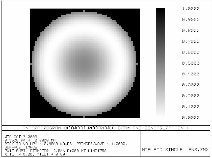
30 Interferometer Picture
31 RMS Wavefront Error versus Field
32 RMS Spot Radius vs Field
33 Strehl Ratio
34 Aberration Summar
35 Field Curvature and Distortion Under Miscellaneous Can also get Grid Diagram
36 Reading W. Smith Modern Optical Engineering Chapter 15
Physical Optics. Lecture 3: Fourier optics Herbert Gross.
 Phsical Optics Lecture 3: Fourier optics 8-4-5 Herbert Gross www.iap.uni-jena.de Phsical Optics: Content No Date Subject Ref Detailed Content.4. Wave optics G Comple fields, wave equation, k-vectors, interference,
Lens Design II. Lecture 1: Aberrations and optimization Herbert Gross. Winter term
 Lens Design II Lecture 1: Aberrations and optimization 18-1-17 Herbert Gross Winter term 18 www.iap.uni-jena.de Preliminary Schedule Lens Design II 18 1 17.1. Aberrations and optimization Repetition 4.1.
Today. MIT 2.71/2.710 Optics 11/10/04 wk10-b-1
 Today Review of spatial filtering with coherent illumination Derivation of the lens law using wave optics Point-spread function of a system with incoherent illumination The Modulation Transfer Function
Introduction to aberrations OPTI518 Lecture 5
 Introduction to aberrations OPTI518 Lecture 5 Second-order terms 1 Second-order terms W H W W H W H W, cos 2 2 000 200 111 020 Piston Change of image location Change of magnification 2 Reference for OPD
Vectorial diffraction theory
 -9- Vectorial diffraction theor Xlab Group Seminar March 8 th, 3 Jeongmin Kim PhD student in Mechanical Engineering Imaging theor Object Imaging sstem Image dimension, transmittance, scattering, fluorescent?,
Lens Design II. Lecture 1: Aberrations and optimization Herbert Gross. Winter term
 Lens Design II Lecture 1: Aberrations and otimization 15-1-19 Herbert Gross Winter term 16 www.ia.uni-jena.de Preliminar Schedule 1 19.1. Aberrations and otimization Reetition 6.1. Structural modifications
Modulation Transfert Function
 Modulation Transfert Function Summary Reminders : coherent illumination Incoherent illumination Measurement of the : Sine-wave and square-wave targets Some examples Reminders : coherent illumination We
Design and Correction of Optical Systems
 Design and Correction of Optical Systems Lecture 7: PSF and Optical transfer function 017-05-0 Herbert Gross Summer term 017 www.iap.uni-jena.de Preliminary Schedule - DCS 017 1 07.04. Basics 1.04. Materials
2.71. Final examination. 3 hours (9am 12 noon) Total pages: 7 (seven) PLEASE DO NOT TURN OVER UNTIL EXAM STARTS PLEASE RETURN THIS BOOKLET
 Total pages: 7 (seven) PLEASE DO NOT TURN OVER UNTIL EXAM STARTS PLEASE RETURN THIS BOOKLET") 2.71 Final examination 3 hours (9am 12 noon) Total pages: 7 (seven) PLEASE DO NOT TURN OVER UNTIL EXAM STARTS Name: PLEASE RETURN THIS BOOKLET WITH YOUR SOLUTION SHEET(S) MASSACHUSETTS INSTITUTE OF TECHNOLOGY
2.71 Final examination 3 hours (9am 12 noon) Total pages: 7 (seven) PLEASE DO NOT TURN OVER UNTIL EXAM STARTS Name: PLEASE RETURN THIS BOOKLET WITH YOUR SOLUTION SHEET(S) MASSACHUSETTS INSTITUTE OF TECHNOLOGY
Optics for Engineers Chapter 11
 Optics for Engineers Chapter 11 Charles A. DiMarzio Northeastern University Nov. 212 Fourier Optics Terminology Field Plane Fourier Plane C Field Amplitude, E(x, y) Ẽ(f x, f y ) Amplitude Point Spread
Optics for Engineers Chapter 11
 Optics for Engineers Chapter 11 Charles A. DiMarzio Northeastern University Apr. 214 Fourier Optics Terminology Apr. 214 c C. DiMarzio (Based on Optics for Engineers, CRC Press) slides11r1 1 Fourier Optics
Design and Correction of optical Systems
 Design and Correction of optical Systems Part 10: Performance criteria 1 Summer term 01 Herbert Gross Overview 1. Basics 01-04-18. Materials 01-04-5 3. Components 01-05-0 4. Paraxial optics 01-05-09 5.
Wavefront Sensing using Polarization Shearing Interferometer. A report on the work done for my Ph.D. J.P.Lancelot
 Wavefront Sensing using Polarization Shearing Interferometer A report on the work done for my Ph.D J.P.Lancelot CONTENTS 1. Introduction 2. Imaging Through Atmospheric turbulence 2.1 The statistics of
AOL Spring Wavefront Sensing. Figure 1: Principle of operation of the Shack-Hartmann wavefront sensor
 AOL Spring Wavefront Sensing The Shack Hartmann Wavefront Sensor system provides accurate, high-speed measurements of the wavefront shape and intensity distribution of beams by analyzing the location and
n The visual examination of the image of a point source is one of the most basic and important tests that can be performed.
 8.2.11 Star Test n The visual examination of the image of a point source is one of the most basic and important tests that can be performed. Interpretation of the image is to a large degree a matter of
Design and Correction of Optical Systems
 Design and Correction of Optical Sstems Lecture 4: Further topics 5-7-5 Herbert Gross Summer term 5 www.iap.uni-jena.de Preliminar Schedule 5.4. Basics.4. Materials and Components 3 9.4. Paraial Optics
Geometric aberrations: introduction, definitions, bibliography
 Geometric aberrations: introduction, definitions, aberrations tpes, bibliograph Geometric aberrations : sometimes called monochromatic aberrations Thierr Lépine - Optical design Transverse ra aberrations
SIMG Optics for Imaging Solutions to Final Exam
 SIMG-733-009 Optics for Imaging Solutions to Final Exam. An imaging system consists of two identical thin lenses each with focal length f = f = +300 mm and diameter d = d =50mm. The lenses are separated
5. LIGHT MICROSCOPY Abbe s theory of imaging
 5. LIGHT MICROSCOPY. We use Fourier optics to describe coherent image formation, imaging obtained by illuminating the specimen with spatially coherent light. We define resolution, contrast, and phase-sensitive
Interference, Diffraction and Fourier Theory. ATI 2014 Lecture 02! Keller and Kenworthy
 Interference, Diffraction and Fourier Theory ATI 2014 Lecture 02! Keller and Kenworthy The three major branches of optics Geometrical Optics Light travels as straight rays Physical Optics Light can be
On the FPA infrared camera transfer function calculation
 On the FPA infrared camera transfer function calculation (1) CERTES, Université Paris XII Val de Marne, Créteil, France (2) LTM, Université de Bourgogne, Le Creusot, France by S. Datcu 1, L. Ibos 1,Y.
Lecture 19 Optical MEMS (1)
") EEL6935 Advanced MEMS (Spring 5) Instructor: Dr. Huikai Xie Lecture 19 Optical MEMS (1) Agenda: Optics Review EEL6935 Advanced MEMS 5 H. Xie 3/8/5 1 Optics Review Nature of Light Reflection and Refraction
EEL6935 Advanced MEMS (Spring 5) Instructor: Dr. Huikai Xie Lecture 19 Optical MEMS (1) Agenda: Optics Review EEL6935 Advanced MEMS 5 H. Xie 3/8/5 1 Optics Review Nature of Light Reflection and Refraction
The spatial frequency domain
 The spatial frequenc /3/5 wk9-a- Recall: plane wave propagation λ z= θ path dela increases linearl with E ep i2π sinθ + λ z i2π cosθ λ z plane of observation /3/5 wk9-a-2 Spatial frequenc angle of propagation?
Chapter 6 Aberrations
 EE90F Chapter 6 Aberrations As we have seen, spherical lenses only obey Gaussian lens law in the paraxial approxiation. Deviations fro this ideal are called aberrations. F Rays toward the edge of the pupil
2.710 Optics Spring 09 Problem Set #6 Posted Monday, Apr. 6, 2009 Due Wednesday, Apr. 15, 2009
 MASSACHUSETTS INSTITUTE OF TECHNOLOGY 2.710 Optics Spring 09 Problem Set #6 Posted Monday, Apr. 6, 2009 Due Wednesday, Apr. 15, 2009 1. Grating with tilted plane wave illumination Consider a sinusoidal
Nature of Light Part 2
 Nature of Light Part 2 Fresnel Coefficients From Helmholts equation see imaging conditions for Single lens 4F system Diffraction ranges Rayleigh Range Diffraction limited resolution Interference Newton
Response of DIMM turbulence sensor
 Response of DIMM turbulence sensor A. Tokovinin Version 1. December 20, 2006 [tdimm/doc/dimmsensor.tex] 1 Introduction Differential Image Motion Monitor (DIMM) is an instrument destined to measure optical
Physical Optics. Lecture 2: Diffraction Herbert Gross.
 Physical Optics Lecture : Diffraction 018-04-18 Herbert Gross www.iap.uni-jena.de Physical Optics: Content No Date Subject Ref Detailed Content 1 11.04. Wave optics G Complex fields, wave equation, k-vectors,
Optical Design with Zemax
 Otical Design with Zema Lecture 9: Imaging 13-1-8 Herbert Gross Winter term 1 www.ia.uni-jena.de Time schedule 1 16.1. Introduction Introduction, Zema interface, menues, file handling, references, Editors,
Lecture 4: Optics / C2: Quantum Information and Laser Science
 Lecture 4: ptics / C2: Quantum Information and Laser Science November 4, 2008 Gaussian Beam An important class of propagation problem concerns well-collimated, spatiall localized beams, such as those emanating
Astronomy 203/403, Fall 1999
 Astronom 0/40 all 999 8 ecture 8 September 999 8 ff-axis aberrations of a paraboloidal mirror Since paraboloids have no spherical aberration the provide the cleanest wa to stud the other primar aberrations
Microscopy. Lecture 3: Physical optics of widefield microscopes Herbert Gross. Winter term
 Microscopy Lecture 3: Physical optics of widefield microscopes --9 Herbert Gross Winter term www.iap.uni-jena.de Preliminary time schedule No Date Main subject Detailed topics Lecturer 5.. Optical system
DIGITAL CORRELATION OF FIRST ORDER SPACE TIME IN A FLUCTUATING MEDIUM
 DIGITAL CORRELATION OF FIRST ORDER SPACE TIME IN A FLUCTUATING MEDIUM Budi Santoso Center For Partnership in Nuclear Technolog, National Nuclear Energ Agenc (BATAN) Puspiptek, Serpong ABSTRACT DIGITAL
PH880 Topics in Physics
 PH880 Topics in Physics Modern Optical Imaging (Fall 2010) Monday Fourier Optics Overview of week 3 Transmission function, Diffraction 4f telescopic system PSF, OTF Wednesday Conjugate Plane Bih Bright
Final examination. 3 hours (9am 12 noon) Total pages: 7 (seven) PLEASE DO NOT TURN OVER UNTIL EXAM STARTS PLEASE RETURN THIS BOOKLET
 Total pages: 7 (seven) PLEASE DO NOT TURN OVER UNTIL EXAM STARTS PLEASE RETURN THIS BOOKLET") 2.710 Final examination 3 hours (9am 12 noon) Total pages: 7 (seven) PLEASE DO NOT TURN OVER UNTIL EXAM STARTS Name: PLEASE RETURN THIS BOOKLET WITH YOUR SOLUTION SHEET(S) MASSACHUSETTS INSTITUTE OF TECHNOLOGY
2.710 Final examination 3 hours (9am 12 noon) Total pages: 7 (seven) PLEASE DO NOT TURN OVER UNTIL EXAM STARTS Name: PLEASE RETURN THIS BOOKLET WITH YOUR SOLUTION SHEET(S) MASSACHUSETTS INSTITUTE OF TECHNOLOGY
Optical/IR Observational Astronomy Telescopes I: Optical Principles. David Buckley, SAAO. 24 Feb 2012 NASSP OT1: Telescopes I-1
 David Buckley, SAAO 24 Feb 2012 NASSP OT1: Telescopes I-1 1 What Do Telescopes Do? They collect light They form images of distant objects The images are analyzed by instruments The human eye Photographic
Dislocation networks in graphite
 Dislocation networks in graphite High Resolution Microscop With Reference to Lattice Fringe Imaging in a TEM f f r Real space Specimen Reciprocal space hr Point spread function Diffraction pattern Back
PRINCIPLES OF PHYSICAL OPTICS
 PRINCIPLES OF PHYSICAL OPTICS C. A. Bennett University of North Carolina At Asheville WILEY- INTERSCIENCE A JOHN WILEY & SONS, INC., PUBLICATION CONTENTS Preface 1 The Physics of Waves 1 1.1 Introduction
Lecture 16 February 25, 2016
 MTH 262/CME 372: pplied Fourier nalysis and Winter 2016 Elements of Modern Signal Processing Lecture 16 February 25, 2016 Prof. Emmanuel Candes Scribe: Carlos. Sing-Long, Edited by E. Bates 1 Outline genda:
4: Fourier Optics. Lecture 4 Outline. ECE 4606 Undergraduate Optics Lab. Robert R. McLeod, University of Colorado
 Outline 4: Fourier Optics Introduction to Fourier Optics Two dimensional transforms Basic optical laout The coordinate sstem Detailed eample Isotropic low pass Isotropic high pass Low pass in just one
WAVE OPTICS (FOURIER OPTICS)
") WAVE OPTICS (FOURIER OPTICS) ARNAUD DUBOIS October 01 INTRODUCTION... Chapter 1: INTRODUCTION TO WAVE OPTICS... 6 1. POSTULATES OF WAVE OPTICS... 6. MONOCHROMATIC WAVES... 7.1 Complex Wavefunction... 7.
WAVE OPTICS (FOURIER OPTICS) ARNAUD DUBOIS October 01 INTRODUCTION... Chapter 1: INTRODUCTION TO WAVE OPTICS... 6 1. POSTULATES OF WAVE OPTICS... 6. MONOCHROMATIC WAVES... 7.1 Complex Wavefunction... 7.
Fourier transform = F. Introduction to Fourier Optics, J. Goodman Fundamentals of Photonics, B. Saleh &M. Teich. x y x y x y
 Fourier transform Introduction to Fourier Optics, J. Goodman Fundamentals of Photonics, B. Saleh &M. Teich f( x, y) FT g( f, f ) f( x, y) IFT g( f, f ) x x y y + 1 { g( f, ) } x fy { π } f( x, y) = g(
Pupil Replication. Frank Spaan Alan Greenaway Erwan Prot Vincent Mourai
 Pupil Replication Frank Spaan Alan Greenaway Erwan Prot Vincent Mourai PREDRIS Pupil Replication for Extreme Dynamic Range Imaging Spectroscopy Start: 1 April 25 Two years, funded by PPARC Publication:
Fully achromatic nulling interferometer (FANI) for high SNR exoplanet characterization
 for high SNR exoplanet characterization") Fully achromatic nulling interferometer (FANI) for high SNR exoplanet characterization François Hénault Institut de Planétologie et d Astrophysique de Grenoble Université Joseph Fourier Centre National
Fully achromatic nulling interferometer (FANI) for high SNR exoplanet characterization François Hénault Institut de Planétologie et d Astrophysique de Grenoble Université Joseph Fourier Centre National
5. Aberration Theory
 5. Aberration Theory Last lecture Matrix methods in paraxial optics matrix for a two-lens system, principal planes This lecture Wavefront aberrations Chromatic Aberration Third-order (Seidel) aberration
Optical Microscopy: Lecture 4. Interpretation of the 3-Dimensional Images and Fourier Optics. Pavel Zinin HIGP, University of Hawaii, Honolulu, USA
 GG 711: Advanced Techniques in Geophsics and Materials Science Optical Microscop: Lecture 4 Interpretation of the 3-Dimensional Images and Fourier Optics Pavel Zinin HIGP, Universit of Hawaii, Honolulu,
Advanced Lens Design
 Advanced Lens Design Lecture 2: Optimization I 2013-10-22 Herbert Gross Winter term 2013 www.iap.uni-jena.de 2 Preliminar Schedule 1 15.10. Introduction Paraxial optics, ideal lenses, optical sstems, ratrace,
Physical Optics. Lecture 7: Coherence Herbert Gross.
 Physical Optics Lecture 7: Coherence 07-05-7 Herbert Gross www.iap.uni-jena.de Physical Optics: Content No Date Subject Ref Detailed Content 05.04. Wave optics G Complex fields, wave equation, k-vectors,
y R T However, the calculations are easier, when carried out using the polar set of co-ordinates ϕ,r. The relations between the co-ordinates are:
 Curved beams. Introduction Curved beams also called arches were invented about ears ago. he purpose was to form such a structure that would transfer loads, mainl the dead weight, to the ground b the elements
Systems of Linear Equations: Solving by Graphing
 8.1 Sstems of Linear Equations: Solving b Graphing 8.1 OBJECTIVE 1. Find the solution(s) for a set of linear equations b graphing NOTE There is no other ordered pair that satisfies both equations. From
Periodic Structures in FDTD
 EE 5303 Electromagnetic Analsis Using Finite Difference Time Domain Lecture #19 Periodic Structures in FDTD Lecture 19 These notes ma contain coprighted material obtained under fair use rules. Distribution
Applications of the Abbe Sine Condition in Multi-Channel Imaging Systems
 Applications of the Abbe Sine Condition in Multi-Channel Imaging Systems Barbara Kruse, University of Arizona, College of Optical Sciences May 6, 2016 Abstract Background In multi-channel imaging systems,
Fourier transform = F. Introduction to Fourier Optics, J. Goodman Fundamentals of Photonics, B. Saleh &M. Teich. x y x y x y
 Fourier transform Introduction to Fourier Optics, J. Goodman Fundamentals of Photonics, B. Saleh &M. Teich f( x, y) FT g( f, f ) f( x, y) IFT g( f, f ) x x y y + 1 { g( f, ) } x fy { π } f( x, y) = g(
Determination of Young s modulus of glass by Cornu s apparatus
 Determination of Young s modulus of glass b Cornu s apparatus Objective To determine Young s modulus and Poisson s ratio of a glass plate using Cornu s method. Theoretical Background Young s modulus, also
Chapter 3. Theory of measurement
 Chapter. Introduction An energetic He + -ion beam is incident on thermal sodium atoms. Figure. shows the configuration in which the interaction one is determined b the crossing of the laser-, sodium- and
* AIT-4: Aberrations. Copyright 2006, Regents of University of California
 Advanced Issues and Technology (AIT) Modules Purpose: Explain the top advanced issues and concepts in optical projection printing and electron-beam lithography. AIT-: LER and Chemically Amplified Resists
Nonlocal Optical Real Image Formation Theory
 See discussions, stats, and author profiles for this publication at: https://www.researchgate.net/publication/48170933 Nonlocal Optical Real Image Formation Theor Article December 010 Source: arxiv READS
Adaptive Optics Lectures
 Adaptive Optics Lectures 1. Atmospheric turbulence Andrei Tokovinin 1 Resources CTIO: www.ctio.noao.edu/~atokovin/tutorial/index.html CFHT AO tutorial: http://www.cfht.hawaii.edu/instruments/imaging/aob/other-aosystems.html
Version 087 EX4 ditmire (58335) 1
 1") Version 087 EX4 ditmire (58335) This print-out should have 3 questions. Multiple-choice questions ma continue on the next column or page find all choices before answering. 00 (part of ) 0.0 points A material
Version 087 EX4 ditmire (58335) This print-out should have 3 questions. Multiple-choice questions ma continue on the next column or page find all choices before answering. 00 (part of ) 0.0 points A material
3.1 The Plane Mirror Resonator 3.2 The Spherical Mirror Resonator 3.3 Gaussian modes and resonance frequencies 3.4 The Unstable Resonator
 Quantum Electronics Laser Physics Chapter 3 The Optical Resonator 3.1 The Plane Mirror Resonator 3. The Spherical Mirror Resonator 3.3 Gaussian modes and resonance frequencies 3.4 The Unstable Resonator
Optical/IR Observational Astronomy Telescopes I: Telescope Basics. David Buckley, SAAO
 David Buckley, SAAO 17 Feb 2010 1 Some other Telescope Parameters 1. Plate Scale This defines the scale of an image at the telescopes focal surface For a focal plane, with no distortion, this is just related
Survey of Wave Types and Characteristics
 Seminar: Vibrations and Structure-Borne Sound in Civil Engineering Theor and Applications Surve of Wave Tpes and Characteristics Xiuu Gao April 1 st, 2006 Abstract Mechanical waves are waves which propagate
Einstein Classes, Unit No. 102, 103, Vardhman Ring Road Plaza, Vikas Puri Extn., Outer Ring Road New Delhi , Ph. : ,
 1 O P T I C S 1. Define resolving power of a telescope & microscope and give the expression for its resolving power. 2. Explain briefly the formation of mirage in deserts. 3. The radii of curvature of
2.710 Optics Spring 09 Solutions to Problem Set #6 Due Wednesday, Apr. 15, 2009
 MASSACHUSETTS INSTITUTE OF TECHNOLOGY.710 Optics Spring 09 Solutions to Problem Set #6 Due Wednesday, Apr. 15, 009 Problem 1: Grating with tilted plane wave illumination 1. a) In this problem, one dimensional
Diode laser emission
 Lecture 9/1 Diode laser emission x Diode laser emission has oblong cross-section. Y-axis with large divergence angle is called fast axis X-axis with smaller divergence angle is called slow axis Lecture
1. Waves and Particles 2. Interference of Waves 3. Wave Nature of Light
 1. Waves and Particles 2. Interference of Waves 3. Wave Nature of Light 1. Double-Slit Eperiment reading: Chapter 22 2. Single-Slit Diffraction reading: Chapter 22 3. Diffraction Grating reading: Chapter
Fourier Optics - Exam #1 Review
 Fourier Optics - Exam #1 Review Ch. 2 2-D Linear Systems A. Fourier Transforms, theorems. - handout --> your note sheet B. Linear Systems C. Applications of above - sampled data and the DFT (supplement
Effects of birefringence on Fizeau interferometry that uses polarization phase shifting technique
 Effects of birefringence on Fizeau interferometr that uses polarization phase shifting technique Chunu Zhao, Dongel Kang and James H. Burge College of Optical Sciences, the Universit of Arizona 1630 E.
Metrology and Sensing
 Metrology and Sensing Lecture 5: Interferometry I 08--6 Herbert Gross Winter term 08 www.iap.uni-jena.de Schedule Optical Metrology and Sensing 08 No Date Subject Detailed Content 6.0. Introduction Introduction,
High-Resolution. Transmission. Electron Microscopy
 Part 4 High-Resolution Transmission Electron Microscopy 186 Significance high-resolution transmission electron microscopy (HRTEM): resolve object details smaller than 1nm (10 9 m) image the interior of
Physical Optics. Lecture 4: Quality criteria and resolution Herbert Gross.
 Physical Optics Lecture 4: Quality criteria and resolution 018-05-0 Herbert Gross www.iap.uni-jena.de Physical Optics: Content No Date Subject Ref Detailed Content 1 11.04. Wave optics G Complex fields,
Waves, Polarization, and Coherence
 05-0-4 Waves, Polarization, and Coherence Lecture 6 Biophotonics Jae Gwan Kim jaekim@gist.ac.kr, X 0 School of nformation and Communication ngineering Gwangju nstitute of Sciences and Technolog Outline
Mathematics 309 Conic sections and their applicationsn. Chapter 2. Quadric figures. ai,j x i x j + b i x i + c =0. 1. Coordinate changes
 Mathematics 309 Conic sections and their applicationsn Chapter 2. Quadric figures In this chapter want to outline quickl how to decide what figure associated in 2D and 3D to quadratic equations look like.
VS203B midterm exam version A
 VS03B midterm exam version A VS03B Midterm Exam Solutions (versions A and B are the same except for the ordering of multiple choice answers Dr. Roorda Date: April 8 009 Permitted aids: pens/pencils, eraser,
Dielectric metasurfaces for complete control of phase and polarization with subwavelength spatial resolution and high transmission
 DOI:.38/NNANO.25.86 Dielectric metasurfaces for complete control of phase and polarization with subwavelength spatial resolution and high transmission Amir Arbabi, Yu Horie, Mahmood Bagheri, and Andrei
Assignment , 7.1, 7.2, 7.5, 7.11, 7.12, 7.15, TIR and FTIR
 LC45-summer, 1 1. 1.1, 7.1, 7., 7.5, 7.11, 7.1, 7.15, 7.1 1.1. TIR and FTIR a) B considering the electric field component in medium B in Figure 1. (b), eplain how ou can adjust the amount of transmitted
Coherence. This is based on. Chapter 10. Statistical Optics, Fundamentals of Photonics Bahaa E. A. Saleh, Malvin Carl Teich. and
 Coherence This is based on Chapter 10. Statistical Optics, Fundamentals of Photonics Bahaa E. A. Saleh, Malvin Carl Teich and Lecture Note on Laser Technology and Optics Prof. Matti Kaivola Optics and
4: Fourier Optics. Lecture 4 Outline. ECE 4606 Undergraduate Optics Lab. Robert R. McLeod, University of Colorado
 Outline 4: Fourier Optics Introduction to Fourier Optics Two dimensional transforms Basic optical laout The coordinate sstem Detailed eample Isotropic low pass Isotropic high pass Low pass in just one
Lecture 2: Geometrical Optics 1. Spherical Waves. From Waves to Rays. Lenses. Chromatic Aberrations. Mirrors. Outline
 Lecture 2: Geometrical Optics 1 Outline 1 Spherical Waves 2 From Waves to Rays 3 Lenses 4 Chromatic Aberrations 5 Mirrors Christoph U. Keller, Utrecht University, C.U.Keller@uu.nl Astronomical Telescopes
IMPROVING BEAM QUALITY NEW TELESCOPE ALIGNMENT PROCEDURE
 IMPROVING BEAM QUALITY NEW TELESCOPE ALIGNMENT PROCEDURE by Laszlo Sturmann Fiber coupled combiners and visual band observations are more sensitive to telescope alignment problems than bulk combiners in
Vectors and the Geometry of Space
 Chapter 12 Vectors and the Geometr of Space Comments. What does multivariable mean in the name Multivariable Calculus? It means we stud functions that involve more than one variable in either the input
Chapter 1 Graph of Functions
 Graph of Functions Chapter Graph of Functions. Rectangular Coordinate Sstem and Plotting points The Coordinate Plane Quadrant II Quadrant I (0,0) Quadrant III Quadrant IV Figure. The aes divide the plane
Light as Wave Motion p. 1 Huygens' Ideas p. 2 Newton's Ideas p. 8 Complex Numbers p. 10 Simple Harmonic Motion p. 11 Polarized Waves in a Stretched
 Introduction p. xvii Light as Wave Motion p. 1 Huygens' Ideas p. 2 Newton's Ideas p. 8 Complex Numbers p. 10 Simple Harmonic Motion p. 11 Polarized Waves in a Stretched String p. 16 Velocities of Mechanical
15. Polarization. Linear, circular, and elliptical polarization. Mathematics of polarization. Uniaxial crystals. Birefringence.
 15. Polarization Linear, circular, and elliptical polarization Mathematics of polarization Uniaial crstals Birefringence Polarizers Notation: polarization near an interface Parallel ("p") polarization
10.5. Polar Coordinates. 714 Chapter 10: Conic Sections and Polar Coordinates. Definition of Polar Coordinates
 71 Chapter 1: Conic Sections and Polar Coordinates 1.5 Polar Coordinates rigin (pole) r P(r, ) Initial ra FIGURE 1.5 To define polar coordinates for the plane, we start with an origin, called the pole,
Introduction to Interferometer and Coronagraph Imaging
 Introduction to Interferometer and Coronagraph Imaging Wesley A. Traub NASA Jet Propulsion Laboratory and Harvard-Smithsonian Center for Astrophysics Michelson Summer School on Astrometry Caltech, Pasadena
Waves Part III Electromagnetic waves
 Waves Part III Electromagnetic waves Electromagnetic (light) waves Transverse waves Transport energy (and momentum) Can travel through vacuum (!) and certain solids, liquids and gases Do not transport
Metrology and Sensing
 Metrology and Sensing Lecture 5: Interferometry I 017-11-16 Herbert Gross Winter term 017 www.iap.uni-jena.de Preliminary Schedule No Date Subject Detailed Content 1 19.10. Introduction Introduction, optical
CH. 1 FUNDAMENTAL PRINCIPLES OF MECHANICS
 446.201 (Solid echanics) Professor Youn, eng Dong CH. 1 FUNDENTL PRINCIPLES OF ECHNICS Ch. 1 Fundamental Principles of echanics 1 / 14 446.201 (Solid echanics) Professor Youn, eng Dong 1.2 Generalied Procedure
Part 3 - Image Formation
 Part 3 - Image Formation Three classes of scattering outcomes Types of electron microscopes Example SEM image: fly nose Example TEM image: muscle Skeletal muscle. Cell and Tissue Ultrastructure Mercer
Week 7: Interference
 Week 7: Interference Superposition: Till now we have mostly discusssed single waves. While discussing group velocity we did talk briefly about superposing more than one wave. We will now focus on superposition
Long- and short-term average intensity for multi-gaussian beam with a common axis in turbulence
 Chin. Phys. B Vol. 0, No. 1 011) 01407 Long- and short-term average intensity for multi-gaussian beam with a common axis in turbulence Chu Xiu-Xiang ) College of Sciences, Zhejiang Agriculture and Forestry
Lecture 9: Indirect Imaging 2. Two-Element Interferometer. Van Cittert-Zernike Theorem. Aperture Synthesis Imaging. Outline
 Lecture 9: Indirect Imaging 2 Outline 1 Two-Element Interferometer 2 Van Cittert-Zernike Theorem 3 Aperture Synthesis Imaging Cygnus A at 6 cm Image courtesy of NRAO/AUI Very Large Array (VLA), New Mexico,
Answer Explanations. The SAT Subject Tests. Mathematics Level 1 & 2 TO PRACTICE QUESTIONS FROM THE SAT SUBJECT TESTS STUDENT GUIDE
 The SAT Subject Tests Answer Eplanations TO PRACTICE QUESTIONS FROM THE SAT SUBJECT TESTS STUDENT GUIDE Mathematics Level & Visit sat.org/stpractice to get more practice and stud tips for the Subject Test
Heating Beam Pattern Optical Design CO2 Laser Thermal Compensation Bench
 LASER INTERFEROMETER GRAVITATIONAL WAVE OBSERVATORY LIGO Laboratory / LIGO Scientific Collaboration LIGO 4//4 Heating Beam Pattern Optical Design CO Laser Thermal Compensation Bench Michael Smith, David
Phase Retrieval for the Hubble Space Telescope and other Applications Abstract: Introduction: Theory:
 Phase Retrieval for the Hubble Space Telescope and other Applications Stephanie Barnes College of Optical Sciences, University of Arizona, Tucson, Arizona 85721 sab3@email.arizona.edu Abstract: James R.
20. Aberration Theory
 0. Aberration Theory Wavefront aberrations ( 파면수차 ) Chromatic Aberration ( 색수차 ) Third-order (Seidel) aberration theory Spherical aberrations Coma Astigmatism Curvature of Field Distortion Aberrations
MAT 1275: Introduction to Mathematical Analysis. Graphs and Simplest Equations for Basic Trigonometric Functions. y=sin( x) Function
 Function") MAT 275: Introduction to Mathematical Analsis Dr. A. Rozenblum Graphs and Simplest Equations for Basic Trigonometric Functions We consider here three basic functions: sine, cosine and tangent. For them,
MAT 275: Introduction to Mathematical Analsis Dr. A. Rozenblum Graphs and Simplest Equations for Basic Trigonometric Functions We consider here three basic functions: sine, cosine and tangent. For them,
Error Budgets, and Introduction to Class Projects. Lecture 6, ASTR 289
 Error Budgets, and Introduction to Class Projects Lecture 6, ASTR 89 Claire Max UC Santa Cruz January 8, 016 Page 1 What is residual wavefront error? Telescope AO System Science Instrument Very distorted
Efficient sorting of orbital angular momentum states of light
 CHAPTER 6 Efficient sorting of orbital angular momentum states of light We present a method to efficiently sort orbital angular momentum (OAM) states of light using two static optical elements. The optical