Benelux France SKF Multitec Benelux B.V. SKF Equipements Italia SKF Multitec S.p.A. Brasil SKF do Brasil Ltda Mexico SKF de México S.A. de C.
|
|
|
- Liliana Craig
- 6 years ago
- Views:
Transcription

1 Roller screws

2 Servo_press High tonnage press Glue gun Painting gun
3 General General Overview: roller screw nuts Comparing roller screws to ball screws The principle of planetary roller screws The principle of recirculating roller screws Recommendations for selection Basic and static load rating Critical rotating speed for screw shafts Permissible speed limit ubrication Effi ciency and back-driving Axial play and preload Static axial stiffness Screw shaft buckling Materials and heat treatments Shaft design Recommendations for assembly Radial and moment loads Alignment ubrication Designing the screw shaft ends Starting-up the screw Operating temperature Other technical data ead precision according to ISO Preload adjustment Product inspection and certifi cation Product information Service Range Capabilities Range details Flanged thrust bearings, FRBU Standard Range Planetary roller screws: technical data and dimensions Recirculating roller screws: technical data and dimensions Flanged thrust bearings, FRBU Ultra Power Range Technical data and dimension Electro-mechanical cylinders SKF worldwide Calculation formulas Symbols Ordering code


4 General Overview: nuts for roller screws Planetary roller screws Recirculating roller screws


5 General SRC, Cylindrical axial play BRC, backlash elimination TRU/PRU Cylindrical backlash elimination: TRU Preloaded: PRU, Flanged axial play BRF, backlash elimination Flanged backlash elimination: TRK Preloaded: PRK SVC, Cylindrical axial play BVC, backlash elimination PVU Cylindrical preloaded SVF, Flanged axial play BVF, backlash elimination PVK Flange preloaded
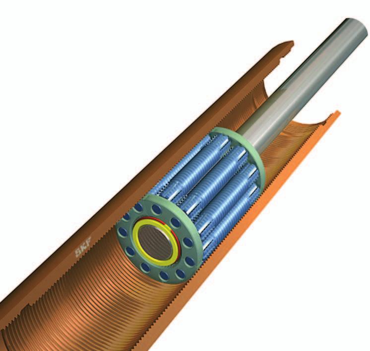
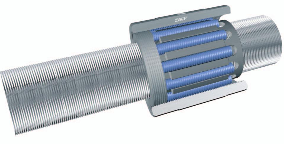
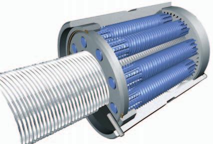
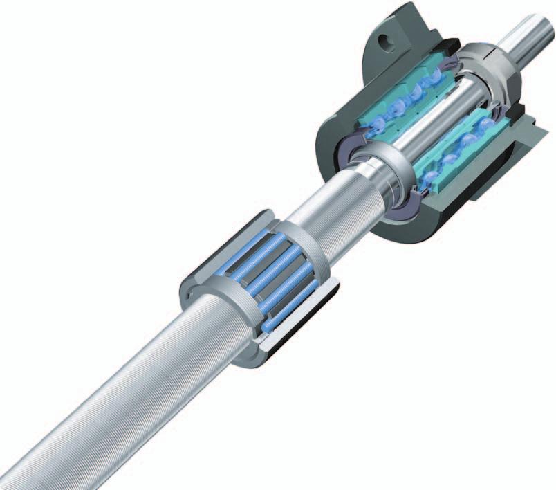
6 General Comparing roller screws to ball screws The load carrying capacity of a rolling screw depends practically on the surfaces at the points of contact: Ball screws n their diameter n the number of contacts n their hardness n their surface fi nish Roller screws n the precision of the contacts to assure load sharing between them. In ball screws, the load is transmitted from the nut to the shaft through the balls engaged in the groove. In a single start ball screw, the ball diameter is limited to approximately 70 % of the lead: there is only a single helix of balls in a nut of given length so the number of contacts is small. In roller screws, the load is transmitted from the nut to the shaft through the barrelled surfaces of all the engaged rollers. The diameter of the contact surface is substantially increased as is the number of points of contact. types of roller screws Planetary roller screw Threaded rollers are the basis of SR / BR / TR / PR planetary roller screws. Recirculating roller screw Grooved rollers are the basis of SV /BV / PV recirculating roller screws. = = = = = = Contact surfaces Diameter Number Hardness Surface finish Precision oad rating E E == = E E Extended life Minimum maintenance costs More reliable operation
 n")
7 General Break out from the limitations of ball screw performance Stainless steels mm ead SR SV SR SV Higher static load up to 000 tonnes SV Adverse environments dust, ice, sand SR SR SV Higher dynamic load up to 00 tonnes SR Shock loads SR SR Higher rotational speed Ø at over 00 rpm Higher acceleration over 000 rad/sec The 0 reasons for using roller screws n High load ratings (SR-SV) n Very high rotational speed (SR) n High acceleration and deceleration rates (SR) n ong life at high cycling rates (SR) n High reliability (SR-SV) n Resistance to hostile surroundings (SR) n Ability to survive shock loads (SR) n Small displacements with very good repeatability (SV) n Rotating the nut when speed becomes critical (SR) n Frequently removing the nut from the screw shaft (SR-most SV). 7

8 General The principle of planetary roller screws fig. Threaded rollers are the basis of SR/BR/TR/PR planetary roller screws. The specific qualities of SKF planetary roller screws Many strong contact surfaces High load carrying capacity ong life No recirculation and no contact No weak points in the nut ess fatigue between rolling elements High rotation speed Robust & shock resistant Guided rollers No loss in preload torque Smooth running when changing direction Timing mechanism Exceptional reliability Ability to work with ice, dirt or poor lubrication Adaptable tooling Non standard and left hand Tailor-made leads available All parts made in house, special steels possible Typical applications The capacity to carry heavy loads for thousands of hours in the most arduous conditions makes SR/BR/TR/PR planetary roller screws suitable for the most demanding applications. The robust nut can withstand shock loads and the timing mechanism ensures reliability even in harsh environments and at high accelerations; the long lead and the symmetrical design of the nut permit high linear speeds. Examples: Plastic molding. Broaching machines. Valves. Presses Machine tools. The steel industry. The tyre industry. Automatic handling. Military aircraft, tanks, rocket launchers, radar, ships and submarines. The nuclear industry.
 Fine resolution Minimum drive torque High mechanical advantage No miniature parts Simple Robust Reliable Many strong")
9 General The principle of recirculating roller screws fig. Grooved rollers are the basis of SV/BV/PV recirculating roller screws. The specific qualities of SKF recirculating roller screws Very small leads (mm) Fine resolution Minimum drive torque High mechanical advantage No miniature parts Simple Robust Reliable Many strong contact Heavy load High rigidity ong life points carrying capacity All parts made in house, special steels possible Typical applications Ultimate positioning accuracy can be obtained using the fi ne lead of SV/BV/PV recirculating roller screws. Their great mechanical advantage minimizes input torque and increases resolution. They can simplify a complete transmission and improve its rigidity. They are often used in applications of advancing technology where reliable optimum performance is vital. Examples: Grinding machines aboratory equipment. Hospital equipment. Paper making The printing industry Telescopes Satellites

10 Recommendations for selection Recommendations for selection Only basic selection parameters are included. To make the very best selection of a roller screw, the designer should specify such critical parameters as the load spectrum, the linear or rotational speed, the rates of acceleration and deceleration, the cycle rate, the environment, the required life, the lead accuracy, the stiffness, and any special requirement. If in doubt, please consult an SKF specialist before placing an order. Basic dynamic load rating (C a ) The dynamic rating is used to compute the fatigue life of roller screws. It is the axial load constant in magnitude and direction, and acting centrally under which the nominal life (as defi ned by ISO) reaches one million revolutions. Nominal fatigue life 0 The nominal life of a roller screw is the number of revolutions (or the number of operating hours at a given constant speed) which the roller screw is capable of enduring before the fi rst sign of fatigue (fl aking, spalling) occurs on one of the rolling surfaces (screw, nut or roller thread or groove). It is however evident from both laboratory tests and practical experience that seemingly identical roller screws operating under identical conditions have different lives, hence the notion of nominal life. It is, in accordance with ISO defi nition, the life achieved or exceeded by 0 % of a suffi ciently large group of apparently identical roller screws, working in identical conditions (alignment, axial and centrally applied load, speed, acceleration, lubrication, temperature and cleanliness). Service life It is the actual life achieved by a specifi c roller screw before it fails. Failure is not only by fatigue (fl aking or spalling); but also by inadequate lubrication and wear; wear of the recirculation system, corrosion, contamination, and, more generally, by loss of the functional characteristics required by the application. Experience acquired with similar applications will help to select the proper screw to obtain the required service life. Also, one must take into account structural requirements such as the strength of screw ends and nut attachments, due to the loads applied on the elements in service. To attain 0 life performance a mean working load of up to 0 % of C a is permitted. In cases where more than 0 % probability of a screw attaining or exceeding its life is required. % reliability Adjusted life ife test bench () SKF can help you to define this value in relation with the actual conditions of service. 0 0 %,00 0 % 0, 0 % 0,3 0 7 % 0, 0 % 0,33 0 % 0, 0
. Radial and moment loads must be taken by linear guiding systems.")
11 Recommendations for selection Equivalent dynamic loads The loads acting on the screw can be calculated according to the laws of mechanics if the external forces (e.g. power transmission, work, rotary and linear inertia forces) are known or can be calculated. It is necessary to calculate the equivalent dynamic load (see page ). Radial and moment loads must be taken by linear guiding systems. It is extremely important to resolve these problems at the earliest conceptual stage. These forces are detrimental to the life and the expected performance of the screw. Fluctuating load When the load fl uctuates during the working cycle, it is necessary to calculate the equivalent dynamic load: this load is defi ned as that hypothetical load, constant in magnitude and direction, acting axially and centrally on the screw which, if applied, would have the same infl uence on the screw life as the actual loads to which the screw is subjected. Additional loads due, for example to misalignment, uneven loading, shocks, and so on, must be taken in account. Their infl uence on the nominal life of the screw is generally taken care of, consult SKF for advice. Static load carrying capacity (C oa ) Roller screws should be selected on the basis of the static load rating C oa instead of on life when they are submitted to continuous or intermittent shock loads, while stationary or rotating at very low speed for short duration. The permissible load is determined by the permanent deformation caused by the load acting at the contact points. It is defi ned by ISO standards as the purely axially and centrally applied static load which will create, by calculation, a total (rolling element + thread surface) permanent deformation equal to of the diameter of curvature of the rolling element. This deformation corresponds to a contact Hertz stress up to 00 MPa depending on the screw diameter. The roller screw must be selected by its basic static load rating which must be, at least, equal to the product of the maximum axial static load applied and a safety factor s o. The safety factor is selected in relation with past experience of similar applications and requirements of running smoothness and noise level (). Critical rotating speed for screw shafts The shaft is equated to a cylinder the diameter of which is the root diameter of the thread. The formulas (see page ) use a parameter the value of which is dictated by the mounting of the screw shaft (whether it is simply supported or fi xed). As a rule the nut is not considered as a support of the screw shaft. Because of the potential inaccuracies in the mounting of the screw assembly, a safety factor of 0.0 is applied to the calculated critical speeds. Calculations which consider the nut as a support of the shaft, or reduce the safety factor, require practical tests and possibly an optimization of the design (). () SKF can help you to define this value in relation with the actual conditions of service.
.")
12 Recommendations for selection Permissible speed limit The permissible speed limit is that speed which a screw cannot reliably exceed at any time. It is generally the limiting speed of the centrifugal forces in the nut. It is expressed as the product of the rpm and the diameter of the screw shaft (in mm). The speed limits quoted in this catalogue (see page ) are the maximum speed that may be applied through very short periods and in optimized running conditions of alignment, light external load and preload with monitored lubrication. Running a screw continuously at the permissible speed limit may lead to a reduction of the calculated life of the nut mechanism.! High speed associated with high load requires a large input torque and yields a relatively short nominal life (). In the case of high acceleration and deceleration, it is recommended to either work under a nominal external load or to apply a light preload to the nut to avoid internal sliding during reversal. The value of the preload of screws submitted to high acceleration is that preload which ensures the rolling elements do not slide (). Too high a preload will create unacceptable increases of the internal temperature. ubrication The key point is the initial lubrication of the nut to lubricate all components. The lubrication of screws rotating at high speed must be properly considered in quantity and quality. The volume, spread and frequency of the application of the lubricant (oil or grease) must be properly selected and monitored. At high speed the lubricant spread on the surface of the screw shaft may be thrown off by centrifugal forces. It is important to monitor this phenomenon during the fi rst run at high speed and possibly adapt the frequency of re-lubrication or the fl ow of lubricant, or select a lubricant with a higher viscosity. Monitoring the steady temperature reached by the nut permits the frequency of re-lubrication or the oil fl ow rate to be optimized. Oil lubrication A centralised recirculating oil system is ideal because it continuously changes the oil in the nut with cooled fi ltered oil from the reservoir. This system is prescribed when the temperature is likely to affect the positioning accuracy. The fl ow of oil can be regulated to optimise fi lm thickness and removal of heat. Selection of oil Mineral oil normally used to lubricate other rotating parts such as bearings and gears may be used for the screw. The viscosity of the oil is defi ned by the speed, running temperature and load. The oil should have a viscosity of 00 ISO at the running temperature. An increase in viscosity or speed will increase the running temperature. At low speed (< 0 rpm) the viscosity should be 00 ISO at the running temperature. Under heavy load an EP additive to improve the fi lm strength is recommended. Corrosion resistant and stabilizing additives may also be used to advantage. Synthetic oils (PAO, ester) are advised for long life, high temperature. Barium soap is advised under heavy load, low speed and when adhesion is required. () SKF can help you to define this value in relation with the actual conditions of service.
13 Recommendations for selection Grease lubrication Where oil lubrication is not practicable, the grease recommended for the support bearings of the screw may also be used for the screw. After a few full strokes the grease will be spread evenly over the useful threaded length of the screw shaft, which will also help to protect the screw against corrosion. However the grease is open to the air. To prevent dirt which may fall on it from entering the nut, wipers should be mounted in each end of the nut. Also the grease on the screw shaft will age more quickly than that in the screw support bearings so more frequent regreasing is needed, especially in a dirty environment. If the screw cannot be dismounted and cleaned before regreasing it is necessary to thoroughly clean the old grease from the screw shaft. This can be done with a spatula and then with a clean fl uff proof cloth. To clean even more a cloth wetted with a solvent such as white spirit may be used. We do not advise using brushes to remove old or spread new grease (risk of bristles coming out). Apply also the new grease through the nut to push out the old from inside the nut. The grease type is defi ned above all by the operating temperature, environment and load on the screw. Speed, starting torque and chemical compatibility may also be taken into consideration. Normally bearing greases of NGI consistency are used. A grease which is too hard at low temperature may restrict rotation or one which is too soft at high temperature may run off. Selection of grease ithium base greases, for standard applications with EP-additives, are generally suitable for use from C to +0 C. A few can be used to +0 C ithium base greases are virtually insoluble in water and very work stable. However they absorb large quantities of water when worked to extremes. ubrication interval The lubrication interval depends on the working cycle of the screw and whether the lubricant is polluted during use. General advice is diffi cult but the following will help you to defi ne the interval. On start up check the grease quality regularly, for instance every month. The fi rst re-lubrication has to be done after roughly revolutions under load, to remove all particles generated during running-in. If the viscosity of the grease sample has increased, it needs replacing. If the grease sample is darker than new it may indicate oxidation or the presence of metallic particles. If it is discoloured, it is probably mixed with water. It is helpful to take samples not only from the part of the screw where running has occured but also from unused parts of the screw where the grease acts as corrosion preventer. () SKF can help you to define this value in relation with the actual conditions of service. 3

14 Recommendations for selection Quantity of lubricant Oil We advise a quantity of cm 3 /h in shots of 0, cm 3 as an order of magnitude depending on the size of the screw and its running conditions. Grease The total volume of grease needed for a new roller screw is the sum of the quantities needed for the screw shaft and the nut. The volume of grease necessary for the screw shaft Z s can be estimated from this formula: Z s =, 0 - d 0 l This quantity of grease should be spread over the whole threaded length of the shaft. The volume of grease for the nut Z n is one third of the free volume in the nut. The quantity Z n is given in the dimension tables: it should be injected through the lubrication hole while turning the shaft. Before applying load the nut should be run twice along the complete stroke to ensure grease is evenly spread. Relubrication, see also Grease lubrication In the case of the existing grease being polluted, remove as much of it as possible and apply the same quantity as when fi rst lubricated. If the existing grease is clean add a volume Z n /3 into the nut. Generally speaking, it is better to inject small quantity frequently than the contrary. Efficiency and back-driving The performance of a screw is mainly dependant on the geometry of the contact surfaces and their fi nish as well as the helix angle of the thread. It is, also, dependant on the working conditions of the screw (load, speed, lubrication, preload, alignment, etc ). The direct effi ciency is used to defi ne the input torque required to transform the rotation of one member into the translation of the other. Conversely, the indirect effi ciency is used to defi ne the axial load required to transform the translation of one member into the rotation of the other one. It is used, also, to defi - ne the braking torque required to prevent that rotation. These screws are reversible or back-driveable under almost all circumstances. It is therefore necessary to design a brake mechanism if backdriving is to be avoided (gear reducers or brake). Preload torque: Internally preloaded screws exhibit a torque due to this preload. This persists even when they are not externally loaded. Preload torque is measured at 0 rpm when assembly is lubricated with ISO grade oil. Starting torque: This is defi ned as the torque needed to overcome the following to start rotation: a) the total inertia of all moving parts accelerated by the energy source (including rotation and linear movement). b) the internal friction of the screw/nut assembly, bearing and associated guiding devices. In general, torque to overcome inertia (a) is greater than friction torque (b). The coeffi cient of friction of the high effi ciency screw when starting µ s is estimated at up to double the dynamic coeffi cient µ, under normal conditions of use. Friction Back driving torque T f > torque T r () SKF can help you to define this value in relation with the actual conditions of service.
15 Recommendations for selection Axial play and preload Preloaded nuts are subject to much less elastic deformation than non-preloaded nuts. Therefore they should be used whenever the accuracy of positioning under load and stiffness are important. Preload, preload torque and rigidity When a roller screw with a whole nut with axial play is measured on a tensile testing machine, a graph similar to (fi g. ) is obtained. One objective of preloading is to eliminate the axial play so that positioning accuracy is improved when the external load changes direction. Planetary roller screws are available with play elimination using whole nut (designation: BR) or split nut (designation: TR). In this case the preload torque will be between 0 and T pe measured at 0 rpm when lubricated with ISO grade oil. Planetary and recirculating roller screws are also available preloaded for optimum rigidity: their designations are PR and PV. (fi g. ) shows how a squeeze load F q is applied to the nut halves and of a split nut to obtain a preload F pr. One part of this load is used to generate the preload force and the other one to squeeze the spacer. The preload spacer is ground to give the correct preload torque when the specifi ed squeeze load is applied. Before the external load is applied the two nut halves are in equilibrium at A (fi g. ) under a load F pr. When an external load F (fi g. 3) is applied the loads on the nut halves become F and F. For all conditions where F,3 F pr the load seen by nut half is greater than the external load so increasing the preload reduces the life of the screw. When the external load reaches,3 F pr nut half is unloaded and F = F. Roller screws are normally preloaded by preloading one nut half against the other so only one half supports the external load in a given direction. In this case, nut half is taking the external load. The load carrying capacity and rigidity of a split preloaded nut are substantially less than a whole nut. Because of the very high load capacity and rigidity of roller screws a split nut is suffi cient for most applications and offers an extremely compact design. - fig. fig. fig. 3 fig. - F pr F pr F q Play Deflection µm oad N F q F pr F F F F q F q oad N A F F F d,3 F pr Deflection µm +
16 Recommendations for selection Figure compares the load/ defl ection characteristics of three different nut combinations: Curve. Whole nut with axial play Curve. Preloaded split nut Curve 3. Preloaded double nut. Backlash elimination can be achieved by fi tting oversize rollers in one-piece nut (BRC-BVC) which allows to keep high load capacities. In exceptional cases where the load rating of a split nut is not suffi cient two whole cylindrical nuts may be preloaded together (fi g. ). Exact dimensions are available on request: please contact SKF. The squeeze load applies a compressive preload in all cases: this ensures more rigidity of the roller screw compared to a preload in extension. Preload torque is the torque resulting from the preload, F pr. The preload torque is calculated from the nominal preload assuming a real effi ciency of 0 % of the theoretical direct effi ciency (page ). The preload torque, T pr = F pr P h 0-3 ( - ) π h p fig. fig oad N Deflection µm
17 Recommendations for selection Preload torque tolerances For each roller screw, preloaded for optimum rigidity a range of value of preload torque, T pr is given in the technical data. The customer is free to choose any value in this range: if no value is specifi ed on the order the mean value will be taken. A typical preload torque graph is shown on page : they can be obtained on request when ordering. The reference R nr value of rigidity correspond to this mean preload torque value. The tolerance of variation of preload torque as the nut moves along the length of the screw depends on the helix angle of the screw thread, the slenderness of the screw shaft and the lead precision. The tables give the tolerances of preload torque variation. Refer to A if the helix angle, a is less than and B if it is more. Preload torque is measured at 0 rpm with ISO grade oil for SR/TR/PR screws and with ISO grade 0 oil for SV/PV screws. A. Tolerance of preload torque for screws with a < l /d 0 0 and l 000 l /d 0 0 and l 000 Tpr G G3 G G G3 G Nm ±% 0, (0,) - 0, (0,) -,0 0 3 (,0) -, 0 0 (,) -, (,3) - 0, B. Tolerance of preload torque for screws with a l l 000 Tpr G3 G G3 G Nm ±% 0-0, Planetary roller screws preloaded for optimum rigidity with a are not available in G lead precision. 7


18 Recommendations for selection Example: A PRK 0 with threaded length 00 mm. The range of preload torque is,,7 Nm. What is the tolerance of preload torque for G3 lead precision? The minimum guaranteed nut rigidity is 70 N/µm and the reference value is 0 N/µm. To obtain these the mean value of preload torque is specified:, Nm. The helix angle a is 3,7. Table A gives ±0 % for G3. All screws will be within the tolerance, ±0 % or,, Nm. If for reasons of motor torque limitations the minimum preload torque, Nm is chosen. The tolerance becomes, ±0 % or 0,, Nm and the preload and minimum guaranteed and reference values of rigidity are not valid. Two typical examples are shown. fig. fig. Preload test bench
19 Recommendations for selection Static axial stiffness of a complete assembly It is the ratio of the external axial load applied on the system and the axial displacement of the face of the nut in relation with the fi xed (anchored) end of the screw shaft. The inverse of the rigidity of the total system is equal to the sum of all the inverses of the rigidity of each of the components (screw shaft, nut as mounted on the shaft, supporting bearing, supporting housings, etc ). = + R t R s R n Shaft rigidity: R s The elastic deformation of screw shaft is proportional to its length and inversely proportional to the square of the root diameter. According to the relative importance of the screw deformation (see rigidity of the total system), too large an increase in the preload of the nut and supporting bearings yields a limited increase of rigidity and notably increases the preload torque and therefore the running temperature. Consequently, the preload stated in the catalogue for each dimension is optimum and should not be increased. fig. fig. l l F F d Because of this, the rigidity of the total system is always less than the smallest individual rigidity. Nut rigidity: R n When a preload is applied to a split nut, fi rstly, the internal play is eliminated, then, the Hertzian elastic deformation increases as the preload applied so that the overall rigidity increases. The theoretical deformation does not take into account machining inaccuracies, actual sharing of the load between the different contact surfaces, the elasticity of the nut and of the screw shaft. The practical stiffness values given in the catalogue are lower than the theoretical values for this reason. They are determined by SKF based on the value of the selected basic preload and an external load equal to twice this preload. d R s = (N/µm) l for standard steel see fi g. d l R s = l (l - l ) for standard steel see fi g. Screw shaft buckling The column loading of the screw shaft must be checked when it is submitted to compression loading (whether dynamically or statically). The maximum permissible compressive load is calculated using the Euler formulas. It is then multiplied by a safety factor of 3 to, depending on the application. The type of end mounting of the shaft is critical to select the proper coeffi cients to be used in the Euler formulas. When the screw shaft comprises a single diameter, the root diameter is used for the calculation. When the screw comprises different sections with various diameters, calculations become more complex (). l () SKF can help you to define this value in relation with the actual conditions of service.
 Standard nuts are machined in 00Cr steel which is through hardened. Hardness of the contact surfaces is -0 HRc.")
. fig. 0 Mpa up to, mm radially from outside. 0 MPa more than, mm radially from outside. Then the Transrol thread is surface hardened by induction.")
20 Recommendations for selection Materials and heat treatments Standard screw shafts are machined from pretreated CrMo. Tensile strength, MPa 0 MPa Yield stress (Rp 0, %) Standard nuts are machined in 00Cr steel which is through hardened. Hardness of the contact surfaces is -0 HRc. Most assemblies made of stainless material have a surface hardness in the range to HRc: the load rating of the catalogue therefore must be derated respectively to C a and C oa C a and C oa being the capacities with the new hardness in Vickers (Hv). fig. 0 Mpa up to, mm radially from outside. 0 MPa more than, mm radially from outside. Then the Transrol thread is surface hardened by induction. ( Hv ) C a = C a ( Hv ) 3 C oa = C oa Through hardening treatment Working environment Our products have not been developed for use in an explosive atmosphere, consequently we cannot take any responsibility for their use in this fi eld. NOTE: CrMo, an AFNOR reference is similar to AISI 0; 00Cr is similar to AISI 00. Shaft Design It is possible to deliver roller screws with one end larger than the outside diameter, d of the shaft. To grind the thread effi - ciently an undercut at root diameter d and length l is needed (fi g. ). When d 3,3 d SR/BR/TR/PR Ph mm, Ph > mm, l mm l, Ph SV/BV/PV Ph = + 0, 0, l mm } 3 All others l mm When d 3,3 d, contact SKF 0 Induction hardening
21 Recommendations for selection Zone A. Torsion only Zone B. Axial + torsional stresses fig. The nominal shear stress t caused by the drive torque T is given by: T t = p d 3 This is increased by a stress concentration factor f to give the real shear stress, t p t p = f t According to Von Mises the total stress, s t s t =,73 t p For safety st should be less than 7 % of the 0, % proof stress of the steel. If the end diameter d includes a keyway of depth e calculate with (d - e). The angle of twist of the screw shaft is given by 0,0 Tl q = d o The nominal axial stress caused by the axial load F is given by F s = pd This is increased by a stress concentration factor f to give the real principal stress s p s p = f s as above t p = f t According to Von Mises the total stress s t s t = (s p + 3 t t ) / For safety s t should be less than 7 % of the 0, % proof stress of the steel. d r ZONE A d r d 3 ZONE B Strength of machined ends The end machining of a roller screw is designed by the customer. Due to the high static and dynamic load ratings of roller screws it is important to check the strength of the machined ends. This checking must be your responsibility unless you specifi - cally ask SKF. This simple approach takes into account the different diameters of the end where stress concentration factors must be used: it takes into consideration only axial and torsional stresses. The linear positioning error, d, caused by this twist P h q d = 30 Nota: Stress concentration factors f and f are available in all general mechanical literature.
.")
 please specify when requesting a quotation or ordering.")
22 Recommendations for selection Manufacturing precision Generally speaking, the precision indication given in the designation defi nes the lead precision: see page. ead precision according to ISO (ex. G - G ). Parameters other than lead precision correspond to our internal standards (generally based on ISO 30-3 class ). If you require special tolerances (for example class or 3) please specify when requesting a quotation or ordering. Inspection of surface fi nish ead error control interferometric test bench
23 Recommendations for assembly Recommended assembly procedure Roller screws are precision components and should be handled with care to avoid shocks. When stored out of the shipping crate they must lie on wooden or plastic vee blocks and should not be allowed to sag. Screw assemblies are shipped in a carboard/wooden crate, wrapped in a sealed plastic bag which protects them from foreign material and possible pollution. They should stay wrapped until they are used. Radial and moment loads Any radial or moment load on the nut will overload some of the contact surfaces, thus signifi cantly reducing its life. (fi g. ) Alignment SKF linear guidance components should be used to ensure correct alignment and avoid non-axial loading. The parallelism of the screw shaft with the guiding devices must be checked. If external linear guidance prove impractical, we suggest mounting the nut on trunnions or gimbals and the screw shaft in self-aligning bearings. Mounting the screw in tension helps align it properly and eliminates buckling. ubrication Good lubrication is essential for the proper functioning of the screw and for its long term reliability (), (see fi g. ). Before shipping, the screw is coated with a protective fl uid that dries to a fi lm. This protective fi lm is not a lubricant. Depending on the selected lubricant, it may be necessary to remove this fi lm before applying the lubricant (there may be a risk of non-compatibility). If this operation is performed in a potentially polluted atmosphere it is highly recommended to proceed with a thorough cleaning of the assembly. Designing the screw shaft ends Generally speaking, when the ends of the screw shaft are specifi ed by the customer s engineering personnel, it is their responsability to check the strength of these ends. Roller screws can be supplied with one end bigger than the diameter of the threaded portion. The core strength of such an end may be affected by large reductions of diameter. When this concept of a large end is used, a minimum length at root diameter is needed between the end of the thread and the face of the larger diameter. Starting-up the screw After the assembly has been cleaned, mounted and lubricated, it is recommended that the nut is allowed to make several full strokes at low speed; to check the proper positioning of the limit switches or reversing mechanism before applying the full load and the full speed. Operating temperature Screws made from standard steel (see page 0) and operating under normal loads can sustain temperatures in the range -0 C to +0 C. Between 0 C and C, SKF must be notifi ed so that it adapts the annealing procedure and checks that the application can be successful with a hardness below the standard minimum value. Above + Celsius, steels adapted to the temperature of the application should be selected, which could decrease the load rating. Consult SKF for advice. NOTE: Operating at high temperature will lower the hardness of the steel, alter the accuracy of the thread and may increase the oxidability of the materials. fig. fig. 3 () SKF can help you to define this value in relation with the actual conditions of service. 3

24 Technical data ead precision according to ISO ead precision is measured at 0 C on the useful stroke l u, which is the threaded length decreased, at each end, by the length l e equal to the screw shaft diameter. G G3 G V 0p µm 3 l u e p v up e p v up e p v up mm µm (3) (00) (00) () (00) (000) (0) - 00 (00) (000) (00) (30) (000) (000) ead accuracy control on a complete assembly over one revolution
25 Technical data l u l e l o l s = useful travel = excess travel (no lead precision required) = nominal travel = specifi ed travel c = travel compensation (difference between ls and lo to be defi ned by the customer, for instance to compensate for expansion) e p = tolerance over the specifi ed travel V = travel variation (or permissible band width) V 0p = maximum permitted travel variation over 0 mm = maximum permitted travel variation over the useful V up travel l u V 0a = measured travel variation over 0 mm = measured travel variation over the useful travel V ua fig. Case with value of c specified by the customer. fig. Case with c = 0 = standard version in case of no value given by the customer. fig. 3
26 Technical data Preload adjustment SRC/BRC Cylindrical nuts In the case of cylindrical nuts (types TRU and PRU for planetary roller screws - type PVU for recirculating roller screws), the threaded housing stoppers must be tightened to the values shown into tables and below. These torques can also be used with one-piece nuts (SRC - BRC - SVC - BVC). Table SRC/BRC/TRU/PRU Housing stopper Tightening Squeeze thread torque load d 0 mm Nm N TRU/PRU Spacer SVC/BVC The standard nut is through hardened to d 0 HRc: under some load conditions it is necessary to use hardened & ground spacers (S) to avoid bedding of the nut into the housing & stopper resulting in loss of preload and rigidity. Table SVC/BVC/PVU Housing stopper Tightening Squeeze thread torque load d mm Nm N PVU Spacer

27 Technical data Preload adjustment Flanged nuts For fl anged nuts (types TRK and PRK for planetary roller screws - type PVK for recirculating roller screws), fi xing bolts must be tightened according to table 3. Table 3 /PVK d (T/PRK) (PVK) Number of Screw Tightening screws size torque M M M M M M M M M M M M M0 M M0 M M0 M M M M M M M Nm Product inspection and certification Special inspection reports or certifi cates can be provided and tailored to individual needs on request. The following are available: - Certifi cate of conformance - ead precision curve 3 - Dimensional inspection reports - Stiffness curves - Magnetic particle inspection - Raw materiel conformity from supplier 7 - Chemical analysis - Heat treatment - Induction hardening 0 - Manufacturing & checking list Quality assured Transrol is certifi ed ISO 00/000 as well as ISO 00. Process running for OHSAS 00. 7

28 Service Range Planetary roller screws with bearing units Delivery time Nuts week without end machining weeks with machined ends g With backlash elimination by oversize rollers: BRC. Delivery time Nuts weeks with machined ends to customer drawing g With axial play: SRC- g With backlash elimination: TRU-TRK g Preloaded: PRU-PRK for optimum rigidity. Details page Capabilities g Machined ends: premachined shafts for machining by the customer to customer drawing (see general rules) suitable for FRBU units. g Screw dimensions: see page. Details page 3 Capabilities g Machined ends to customer drawing (see general rules). g Screw dimensions: up to 00 mm maxi length up to 00 mm threaded length. GENERA RUES FOR A THE SERVICE RANGE up to 3 pieces. lead precision: G to ISO standard. standard nuts, standard steel (no special documents such as conformity report). lubrication: screw assemblies delivered with machined ends are greased with SKF GEP (temperature range: -0 C / +0 C); without end machining, they are only protected with rust inhibitor.

29 Service Range Recirculating roller screws with bearing units Delivery time Nuts week without end machining weeks with machined ends g With backlash elimination by oversize rollers: BVC. Delivery time Nuts weeks with machined ends to customer drawing g With axial play: SVC g Preloaded: PVU-PVK for optimum rigidity. Details page 3 Capabilities g Machined ends: premachined shafts for machining by the customer to customer drawing (see general rules) suitable for FRBU units g Screw dimensions: see page 3 Details page 3 Capabilities g Machined ends to customer drawing (see general rules) g Screw dimensions: up to 00 mm maxi length up to 00 mm threaded length RUES (continuation) standard machining: no spline, no hollow shaft, no radius in grinding operations. If any such requirements, order cannot be accepted by the Service Channel. Unless specified, tolerances will be according to class, ISO 30-3 (see page ). FRBU thrust bearing units can be delivered for all sizes. screws for nuclear, aerospace, military or medical applications are excluded.

30 Service Range Planetary roller screws BRC + thrust bearing assembly (option) Thrust bearing FRBU* B 7 B Designation C a C oa T pr * R nr d d d 0 B B R D A w a b H Q B kn kn Nm N/µm BRC x-r BRC x-r BRC x-r BRC 3x-R Key a, d 0, d B D g " 0, b " B d 0 H Wiper R x Wiper w x w x Q ubrication x " " 0, 0, A h B B Screw Thrust bearing B 7 B designation designation BRC x-r BRC x-r BRC x-r BRC 3x-R FRBU FRBU FRBU FRBU End which can be machined to customer requirements. Maximum threaded length: can be cut & machined to customer requirements. N.B.: Nut and thrust bearing unit cannot be modifi ed. In standard version, the fl ange of the thrust bearing is located on the KMT side. * Preload torque measured at 0 rpm with SKF GEP as lubricant.

31 Service Range Recirculating roller screws BVC + thrust bearing assembly (option) Thrust bearing FRBU* B 7 B Designation C a C oa T pr * R nr d d d 0 B B R D A w a b H Q kn kn Nm N/µm BVC 0x-R BVC x-r BVC 3x-R " b Key a " d 0 d d D g 0, H 0, No wiper 0, x R No wiper Q ubrication w x w x x " " 0, A h 0, B B Screw Thrust bearing B 7 B designation designation BVC 0x-R BVC x-r BVC 3x-R FRBU FRBU3 FRBU End which can be machined to customer requirements. Maximum threaded length: can be cut & machined to customer requirements. N.B.: Nut and thrust bearing unit cannot be modifi ed. In standard version, the fl ange of the thrust bearing is located on the KMT side. * Preload torque measured at 0 rpm with SKF GEP as lubricant. 3


32 Service Range Standard nuts - Planetary roller screws d 0 P h N C a C oa Dimensions SRC/ TRU/PRU - SRC/ TRU/PRU -,,3 3,, 0 0,,7,, 7,,0,0 3,,,0 3,0 0,,0 3,0, 0 0 3, 7,, 0,3 3, 0,0 0,, 0, 0,3 7,3 7,3,,, 7, See pages 3 to ,, 7,,0, 70, 3, 3, 0,0 3, 0, 7,, 7, 0,7 37, Standard nuts - Recirculating roller screws d 0 P h N C a C oa Dimensions SVC PVU-PVK SVC PVU-PVK,,,,,,,, 0 0,, 0, 0, 3, 3,,3, , 3,,3,3,, 3, 3,,,,, 3, 3, 7, 7, See pages to ,,,,7 3, 7,,, 3
33 Service Range Flanged thrust bearing units, E D D D D 3 D, 3 Ø 0, xs 0 x In standard version, the FRBU thrust bearing unit is assembled according to drawing page or 3. If you require a different assembly, please indicate it when ordering. Greased for life with SKF GEP. Angular contact ball bearing (0 ) ock nut Basic load rating Number Bearing Maximum Axial Tilt High precision KMT nut (axial) of designation preload rigidity rigidity bearings torque * Flanged C a C oa Designation Hook Tightening Grub screws bearing spanner torque (Nm) Size Max. unit kn kn Nm N/µm Nm/mrad Nm tightening designation torque (Nm) FRBU BEGBP 0. 0 KMT 3 HN M FRBU BEGBP KMT HN M FRBU BEGBP KMT HN M FRBU BEGBP KMT 7 HN 7 M FRBU BEGBP KMT 0 HN 0 70 M Nota: other sizes available: see page -0. Dimensions (mm) Flanged bearing 3 D D D3 D D S Fixing E unit designation h7 H3 screws FRBU M 3 FRBU M 3 FRBU M0 3 FRBU M 0 7 FRBU M 0 7, * Preload torque measured at 0 rpm with SKF GEP as lubricant. 33
34 R b QE R a QB b b b a d d G d l cx cx b a x d 7 G B 3 B B B Dimensions (mm) Thrust bearing units FRBU d d d B B B B 3 G G c b a d 7 R a R b a b b b h h7 js js g h N M FRBU M FRBU M FRBU M FRBU M Undercut l is defi ned p0. d can be equal to the root diameter for some sizes. 3


35 Standard Range: contents Planetary roller screws: technical data and dimensions Cylindrical nuts with axial play, SRC... 3 Flanged nuts with axial play,... Preloaded cylindrical nuts, TRU/PRU... 0 Preloaded fl anged nuts,... Recirculating roller screws: technical data and dimensions Cylindrical nuts with axial play, SVC... Flanged nuts with axial play, SVF... Preloaded cylindrical nuts, PVU... Preloaded fl anged nuts, PVK Flanged thrust bearing unit, FRBU... & 7 3
36 Standard Range The full range of SR planetary roller screws 3
 n Robust design to withstand shock loads n Choice of 3 classes of lead precision n Planetary")
37 SKF planetary roller screws The robust screw for long life in tough conditions has these advantages n Very high load carrying capacity n Very long life n High rotational speed and long lead permit linear speed up to 0 metres/minute n Planetary timing mechanism permits high acceleration (> 000 rad/sec ) n Robust design to withstand shock loads n Choice of 3 classes of lead precision n Planetary timing mechanism ensures correct functioning even in adverse environments such as ice, dirt or poor lubrication n Special and left hand leads easily available n Special steels available n Special surface treatments and lubrication available n Nut removal without losing rolling elements n Cylindrical and fl anged nuts, with play or preloaded n Built in wipers available in all cases. Backlash elimination with oversize rollers: as an option under following conditions: total length g d 0 threaded length g d 0 37
38 Cylindrical nuts with axial play, SRC Backlash elimination with oversize rollers as an option (BRC) d 0 g 3 mm Standard Threaded rollers Customised d 0 P h N l tp a N r Nmax C a C oa S ap m n m s I s I nn I ns Z n Designation mm mm mm kn kn mm kg kg/m kgmm /m kgmm kgmm cm 3 00,0 7,, 0,0 0, 0, 3,, 0, 0, SRC x 70 7, 7,73,7 0,0 0, 0,,0, 0,,3 SRC x 7 7,0,7 0, 7,3 3, 0,7 0,0 0,0 0, 0,,, 3,0 3,0,,,,,, SRC x SRC x 0 0,,3, 0,0 0,3,3 3,3 7,,,7 SRC 0x ,33,0,, 0 0,,77,,,7, 3,0 0,0 0,0 0,0 0,0 0, 0, 0, 0,,7,7,7,7,,,,,,,,,,,,,03,03,03,03 SRC x SRC x SRC x SRC x ,,0 3, 7,,7,3 0,0 0,0 0, 0, 3, 3,,7,7 73, 73,,3,3,, SRC x SRC x , 7, 0, 0 3, 7,3 7,7 0,3 0,3 0,3 0,0 0,0 0,7 0,7 0,7 3, 3, 3,,0,0,0 3, 3, 3,,3,3,3 0, 0, 0, SRC x SRC x0 SRC x ,0 3,3,0, 0,,00 0,3 3, 7,3 7,3 7,3 77, 0,0 0,0 0,0,,,,,,,,,,,, 7, 7, 7, 7, 3, 3, 3, 3, 3,7 3,7 3,7 3,7 SRC x SRC x SRC x0 SRC x ,0,,0,0, 3 Designation: page 7 - Symbols: page 3 0, 7, 0,0, 3,0 7,3,0 7,7,3 0,0 0,0 0,0,,,,,,0,0,0,0,0 E E E E E,, 73, 73, 73,,7,7,7,7,7 3, 3, 3, 3, 3, SRC 3x SRC 3x SRC 3x SRC 3x SRC 3x
39 A 0, " b " 0, B B a Wiper recess 0, Wiper on request d d 0 d D 3 D D H w x w x Q " " d 0 d d D A w a b H Q B D D 3 Designation g/h7 h h mm mm mm mm mm mm mm mm mm mm mm mm mm SRC x, 7,3 0,, 3,0 3 SRC x,,3 0, 3, 3,0 7 SRC x SRC x,,,3, , 0, 3, 3, 3 3,0,0 0 0 SRC 0x SRC x SRC x SRC x SRC x0 0 0,,,,,,3 0,3 0,3 0,0, , 0, 0, 0, 0, , 3,0 0, 0, 0, 0, SRC x SRC x,, 3,3,7 0, 0, 0 0 0,0 0,0,0,0 3 3 SRC x SRC x0 SRC x,,,,3 3,7 3, , 0, 0,,,, SRC x SRC x SRC x0 SRC x0,,, 3,,3,3,7 7, 0, 0, 0, 0, ,,,, ,0,0,0, SRC 3x SRC 3x SRC 3x SRC 3x SRC 3x , 3, 3, 37, 37, 3,3 3, 3,7 3, 33, , 0, 0, 0, 0, 70,0 70,0 70,0 70,0 70,0,0,0,0,0,0 3
40 Cylindrical nuts with axial play, SRC Backlash elimination with oversize rollers as an option (BRC) d 0 3 g mm Standard Threaded rollers Customised d 0 P h N l tp a N r Nmax C a C oa S ap m n m s I s I nn I ns Z n Designation mm mm mm kn kn mm kg kg/m kgmm /m kgmm kgmm cm ,3,7,,7,3 0 0,, 7, 7, 7,7, 70,3 7, 0,,00 0,0 0,0,,,,,,,,,, 7E 7E 7E 7E 7E 03E 03E 03E 03E 03E,, 3, 3, 3, 7, 7, 7, 7, 7, SRC 3x SRC 3x0 SRC 3x SRC 3x0 SRC 3x ,, 7,,, 3 3, 3,7 7,7 7,,,7,7,,, 0,0 0,0,7,7,7,7,7,,,,, E E E E E 73E 73E 73E 73E 73E,,,3,3,3,,,,, SRC x SRC x SRC x SRC x SRC x ,0 3,03 3,7, 7,, 0,0,3 3, 7,7,,,3 70, 7,,3,7,0 0,0 0,0 0,0,,,,,,,,,,,, 0E 0E 0E 0E 0E 0E E E E E E E 370, 370, 370, 370, 370, 3,,0,0,0,0,0,0 SRC x SRC x SRC x0 SRC x SRC x0 SRC x ,0 7,77, 3,0,,0 3,7,,33 33,7 373,0 3,7 33,,, 77, 7, 7, 0,0 0,0 3, 3, 3, 7,3 7,3 7,3,3,3,3,,, 7E 7E 7E E E E 00E 00E 00E E E E 3,3 33, 33, 0E 0E 0E,,, 03,0 03,0 03,0 SRC x SRC x SRC x3 SRC 0x0 SRC 0x SRC 0x ,,,, 0, 3 3 Designation: page 7 - Symbols: page ,3 3,7 3,3 3,, 73, 7,,,,3 0,0,,,,,,3,3,3,3,3 E E E E E 0E 0E 0E 03E 03E,3,0, 7 7,,0,0,, SRC x SRC x SRC x SRC x SRC x3
41 A 0, " b " 0, B B a Wiper recess 0, Wiper on request d d 0 d D 3 D D H w x w x Q " " d 0 d d D A w a b H Q B D D 3 Designation g/h7 h h mm mm mm mm mm mm mm mm mm mm mm mm mm SRC 3x SRC 3x0 SRC 3x SRC 3x0 SRC 3x , 3, 0, 0, 0, 3,3 37,7 37, 3, 3, ,0,0,0,0, ,0 3,0 3,0 3,0 3, SRC SRC SRC SRC SRC x x x x x,,,,, 3,,7,, 0, , 0, 0, 0, 0, ,,,,, SRC SRC SRC SRC SRC SRC x x x0 x x0 x,,,,,, 7,3 7,,7,,, ,0,0,0,0,0,0 03,0 03,0 03,0 03,0 03,0 03, SRC SRC SRC x x x3, 7,,3,7 3,, ,0,0, ,0 03,0 03, SRC SRC SRC 0x0 0x 0x ,,,,7, 7,,0,0, ,0,0,0 0, 0, 0, SRC SRC SRC SRC SRC x x x x x3,,,,,3,7,, 0, 0,3,0,0,0,0,0,0,0,0,0,

42 Cylindrical nuts with axial play, SRC d 0 7 g 0 mm Standard Threaded rollers Customised d 0 P h N l tp a N r Nmax C a C oa S ap m n m s I s I nn I ns Z n Designation mm mm mm kn kn mm kg kg/m kgmm /m kgmm kgmm cm ,3 3,, 0,, 7,,,,7 0,0,,, 3,7 3,7 3,7 E E E E E E E E E 3,0 3,0 3,0 SRC 7x0 SRC 7x SRC 7x ,73,0,,, ,7,,0,, 3, 7,3,0 3, 0,0,,,,, 3, 3, 3, 3, 3, 3E 3E 3E 3E 3E 0E 0E 0E E E 7E 7E 7E E E 03,0 03,0 03,0 3,0 3,0 SRC 0x SRC 0x SRC 0x SRC 0x3 SRC 0x ,, 0, 3, 0, 70E 07E3 7E 3,0 SRC x ,37 3,,,,7 77E E 3E 00,0 SRC 00x , 3,7 3,0 7,3 037,7 3,0,,, 0E3 0E3 7E3 3E3 E 0E 33,0,0 SRC 0x SRC 0x ,37 3,0 3,,3 0,0,0 7,,7 3,7 3,7 30E3 30E3 E3 3E 7E E3 SRC 0x3 SRC 0x ,0,3 0,0 37,, 0E3 0E 3E3 73,0 SRC 0x ,0,0 Designation: page 7 - Symbols: page 37,,7 7, 0E E 77E3 37 SRC 0x
43 A 0, " b " 0, B B a Wiper recess 0, Wiper on request d d 0 d D 3 D D H w x w x Q " " d 0 d d D A w a b H Q B D D 3 Designation g/h7 h h SRC SRC SRC 7x0 7x 7x0 mm mm mm mm mm mm mm mm mm mm mm mm mm , 7, 7, 73,7 73, 7, 0 0 0,0,0, , 0, 0, SRC SRC SRC SRC SRC 0x 0x 0x 0x3 0x ,,,,3,7 7,7 7, 77, 7,3 7, ,0,0,0,0, , 0, 0, 0, 0, SRC x0 00,, 00 0, 00 0,0 0 SRC 00x 00 0, 7, 0, , SRC 0x SRC 0x 0 0,, 7,, ,0, 00 00,0, SRC 0x3 SRC 0x 0 0,3,,3, ,0 3, ,0, SRC 0x 0,3 7,3 0 3, , SRC 0x 0,3 0, , ,
44 Flanged nuts with axial play, Backlash elimination with oversize rollers as an option (BRF) d 0 g 3 mm Standard Threaded rollers Customised d 0 P h N l tp a N r Nmax C a C oa S ap m n m s I s I nn I ns Z n Designation mm mm mm kn kn mm kg kg/m kgmm /m kgmm kgmm cm 3 00,0 7,, 0,0 0,3 0, 3,, 0, 0, x 70 7, 7,73,7 0,0 0,3 0,,0 0,0 0,,3 x 7 7,0,7 0, 7,3 3, 0,7 0,0 0,0 0, 0,,, 3,0 3,0 0, 0,,,,, x x 0 0,,3, 0,0 0,,3 3,3,,,7 0x ,33,0,, 0 0,,77,,,7, 3,0 0,0 0,0 0,0 0,0 0,7 0,7 0,7 0,7,7,7,7,7,,,, 3, 3, 3, 3,,,,,,03,03,03,03 x x x x ,,0 3, 7,,7,3 0,0 0,0 0, 0, 3, 3,,7,7,,,3,3,, x x , 7, 0, 0 3, 7,3 7,7 0,3 0,3 0,3 0,0 0,0,,, 3, 3, 3,,0,0,0 0E 0E 0E,3,3,3 0, 0, 0, x x0 x ,0 3,3,0, 0,,00 0,3 3, 7,3 7,3 7,3 77, 0,0 0,0 0,0,,,,,,,,,,,, E E E E 3, 3, 3, 3, 3,7 3,7 3,7 3,7 x x x0 x ,0,,0,0, Designation: page 7 - Symbols: page 3 0, 7, 0,0, 3,0 7,3,0 7,7,3 0,0 0,0 0,0,,,,,,0,0,0,0,0 E E E E E 37E 37E 3E 3E 3E,7,7,7,7,7 3, 3, 3, 3, 3, 3x 3x 3x 3x 3x
45 A A A u 0, Wiper on request Q Wiper recess r r 0, +0, D 0 d d 0 d D 3 D D g/h7 D J G Equidistant d 0 d d D A A A D J G r Q u B D D 3 Designation h js +0, mm mm mm mm mm mm mm mm mm mm mm mm mm mm mm x, 7,3,0 3 xm 0, M 3,0 3 x,,3,0 xm 0, M 3,0 7 x x,,,3, ,0,0 xm xm 0, 0, M M 3 3,0, x x x x x0 0 0,,,,,,3 0,3 0,3 0,0,7 0 0,0 3,0 3,0 3,0 3,0 3 xm xm xm xm xm 0, 0, 0, 0, 0, M M M M M 3,0 0, 0, 0, 0, x x,, 3,3,7 0,0 0,0 7 7 xm xm 0, 0, M M,0,0 3 3 x x0 x,,,,3 3,7 3, 7 7 7,0,0, xm xm xm 0, 0, 0, M M M x x x0 x0,,, 3,,3,3,7 7,,0,0,0, xm xm xm xm 0, 0, 0, 0, M M M M ,0,0,0, x 3x 3x 3x 3x , 3, 3, 37, 37, 3,3 3, 3,7 3, 33, ,,,,, xm xm xm xm xm 0, 0, 0, 0, 0, M M M M M,0,0,0,0,0
46 Flanged nuts with axial play, Backlash elimination with oversize rollers as an option (BRF) d 0 3 g mm Standard Threaded rollers Customised d 0 P h N l tp a N r Nmax C a C oa S ap m n m s I s I nn I ns Z n Designation mm mm mm kn kn mm kg kg/m kgmm /m kgmm kgmm cm ,3,7,,7,3 0 0,, 7, 7, 7,7, 70,3 7, 0,,00 0,0 0,0,0,0,0,0,0,,,,, 7E 7E 7E 7E 7E 3E 3E 3E 3E 3E,, 3, 3, 3, 7, 7, 7, 7, 7, 3x 3x0 3x 3x0 3x ,, 7,,, 3 3, 3,7 7,7 7,,,7,7,,, 0,0 0,0 3, 3, 3, 3, 3,,,,,, E E E E E 03E 03E 03E 03E 03E,,,3,3,3,,,,, x x x x x ,0 3,03 3,7, 7,, 0,0,3 3, 7,7,,,3 70, 7,,3,7,0 0,0 0,0 0,0 7, 7, 7, 7, 7, 7,,,,,,, 0E 0E 0E 0E 0E 0E E E E E E E 370, 370, 370, 370, 370, 3,,0,0,0,0,0,0 x x x0 x x0 x ,0 7,77, 3,0,,0 3,7,,33 33,7 373,0 3,7 33,,, 77, 7, 7, 0,0 0,0,,,,,,,3,3,3,,, 7E 7E 7E E E E 3E 3E 3E E E E 3,3 33, 33, 0E 0E 0E,,, 03,0 03,0 03,0 x x x3 0x0 0x 0x ,,,, 0, 3 3 Designation: page 7 - Symbols: page 3 3 3,3 3,7 3,3 3,, 73, 7,,,,3 0,0,3,, 0, 0,,3,3,3,3,3 E E E E E 0E 0E 0E E E,3,0, 7 7,,0,0,, x x x x x3
47 A A A u 0, Wiper on request Q Wiper recess r r 0, +0, D 0 d d 0 d D 3 D D g/h7 D J G Equidistant d 0 d d D A A A D J G r Q u B D D 3 Designation h js +0, mm mm mm mm mm mm mm mm mm mm mm mm mm mm mm 3x 3x0 3x 3x0 3x , 3, 0, 0, 0, 3,3 37,7 37, 3, 3, , 33, 33, 33, 33, xm0 xm0 xm0 xm0 xm0,,,,, M M M M M 73,0 73,0 73,0 73,0 73, x x x x x,,,,, 3,,7,, 0, ,,,,, xm0 xm0 xm0 xm0 xm0,,,,, M M M M M x x x0 x x0 x,,,,,, 7,3 7,,7,,, ,0,0,0,0,0, xm xm xm xm xm xm,,,,,, Mx Mx Mx Mx Mx Mx x x x3, 7,,3,7 3,, , 37, 37, xm xm xm,,, Mx Mx Mx x0 0x 0x ,,,,7, 7, 3, 3, 3, xm xm xm,,, Mx Mx Mx x x x x x3,,,,,3,7,, 0, 0, ,0,0,0,0, xm xm xm xm xm,,,,, Mx Mx Mx Mx Mx

48 Flanged nuts with axial play, d 0 7 g 0 mm Standard Threaded rollers Customised d 0 P h N l tp a N r Nmax C a C oa S ap m n m s I s I nn I ns Z n Designation mm mm mm kn kn mm kg kg/m kgmm /m kgmm kgmm cm ,3 3,, 0,, 7,,,,7 0,0 0, 0, 0, 3,7 3,7 3,7 E E E E3 E3 E3 E E E 3,0 3,0 3,0 7x0 7x 7x ,73,0,,, ,7,,0,, 3, 7,3,0 3, 0,0 7,7 7,7 7,7 7,7 7,7 3, 3, 3, 3, 3, 3E 3E 3E 3E 3E 0E3 0E3 0E3 0E3 0E3 7E 7E 7E E E 03,0 03,0 03,0 3,0 3,0 0x 0x 0x 0x3 0x ,, 0,,3 0, 70E E3 7E 3,0 x ,37 3,,,7,7 77E E3 3E 00,0 00x , 3,7 3,0 7,3 037,7,,0,, 0E3 0E3 E3 E E 0E 33,0,0 0x 0x ,37 3,0 3,,3 0,0,0 03,3, 3,7 3,7 30E3 30E3 0E 3E 7E E3 0x3 0x ,0,3 0,0 3,, 0E3 E 3E3 73,0 0x ,0,0 Designation: page 7 - Symbols: page 37, 7, 7, 0E E 77E3 37 0x
49 A A A u 0, Wiper on request Q Wiper recess r r 0, +0, D 0 d d 0 d D 3 D D g/h7 D J G Equidistant d 0 d d D A A A D J G r Q u B D D 3 Designation h js +0, 7x0 7x 7x0 mm mm mm mm mm mm mm mm mm mm mm mm mm mm mm , 7, 7, 73,7 73, 7, ,0 73,0 73, xm xm xm,,, Mx Mx Mx x 0x 0x 0x3 0x ,,,,3,7 7,7 7, 77, 7,3 7, ,,,,, xm xm xm xm xm,,,,, Mx Mx Mx Mx Mx x0 00,, , 7 xm, Mx 0 00x 00 0, 7, 0 7, 0 0 xm, Mx 0x 0x 0 0,, 7,, ,, 30 0 xm xm,, Mx M x3 0x 0x 0 0 0,3,,3,3, 7, Consult SKF x 0,3 0,
50 Preloaded cylindrical nuts, TRU for backlash elimination PRU for optimum rigidity d 0 g 3 mm Standard Threaded rollers Customised TRU PRU d 0 P h N l tp a N r Nmax C a C oa T pe R ng R nr T pr F pr m n m s I s I nn I ns Z n mm mm mm kn kn Nm N/µm N/µm Nm N kg kg/m kgmm /m kgmm kgmm cm 3 00,0 7,, ,0-0,3 3 0, 0, 3,, 0, 0, 00 7,,77 3,3 0, , - 0, 70 0, 0,,0, 0,, ,0,7 0,,,0 0,3 0, 0, , - 0,3 0, - 0,3 3 0, 0,,, 3,0 3,0,,,,,, 0 00,,7,3 0, , - 0, 0,3,3 3,3 7,,, ,33,0,, 0 7,,0,00 3, 0,,0 3,03, 0,33 0,33 0,33 0, ,3-0,3 0,3-0,3 0,3-0,3 0,3-0, , 0, 0, 0,,7,7,7,7,,,,,,,,,,,,,03,03,03,03 0 0,,0 3 3,3, 3, 3,7 0, 0, ,3-0,7 0,3-0,7 7 0, 0, 3, 3,,7,7 73, 73,,3,3,, , 7, 0, 0 3, 0,0 3,,, 3,0 0, 0, 0, , - 0, 0, - 0, 0, - 0, ,7 0,7 0,7 3, 3, 3,,0,0,0 3, 3, 3,,3,3,3 0, 0, 0, ,0 3,3,0, 0 0,,3, 7,, 7,7 7,, 0, 0, 0, 0, ,7 -,3 0,7 -,3 0,7 -,3 0, -, 70 7,,,,,,,,,,,, 7, 7, 7, 7, 3, 3, 3, 3, 3,7 3,7 3,7 3, ,0,,0,0, 3,3 3,73,73,,0, 3 0,,, 0,0 0,0 0,0 0,0 0, ,77 -,3 0,77 -,3 0,77 -,3 0,77 -,3, -, ,,,,,,0,0,0,0,0 E E E E E,, 73, 73, 73,,7,7,7,7,7 3, 3, 3, 3, 3, Designation: page 7 - Symbols: page 0
51 A 0, " b " 0, B B a Wiper recess 0, Wiper on request d d 0 d D 3 D D H w x Q w x " " d 0 d d D A w a b H Q B D D 3 Designation g/h7 h h mm mm mm mm mm mm mm mm mm mm mm mm mm TRU/PRU x, 7,3 0,, 3,0 3 TRU/PRU x,,3 0, 3, 3,0 7 TRU/PRU TRU/PRU x x,,,3, , 0, 3, 3, 3 3,0,0 0 0 TRU/PRU 0x TRU/PRU x TRU/PRU x TRU/PRU x TRU/PRU x0 0 0,,,,,,3 0,3 0,3 0,0, , 0, 0, 0, 0, , 3,0 0, 0, 0, 0, TRU/PRU x TRU/PRU x,, 3,3,7 0, 0, 0 0 0,0 0,0,0,0 3 3 TRU/PRU TRU/PRU TRU/PRU x x0 x,,,,3 3,7 3, , 0, 0,,,, TRU/PRU TRU/PRU TRU/PRU TRU/PRU x x x0 x0,,, 3,,3,3,7 7, 0, 0, 0, 0, ,,,, ,0,0,0, TRU/PRU TRU/PRU TRU/PRU TRU/PRU TRU/PRU 3x 3x 3x 3x 3x , 3, 3, 37, 37, 3,3 3, 3,7 3, 33, , 0, 0, 0, 0, 70,0 70,0 70,0 70,0 70,0,0,0,0,0,0

52 Preloaded cylindrical nuts, TRU for backlash elimination PRU for optimum rigidity d 0 3 g mm Standard Threaded rollers Customised TRU PRU d 0 P h N l tp a N r Nmax C a C oa T pe R ng R nr T pr F pr m n m s I s I nn I ns Z n mm mm mm kn kn Nm N/µm N/µm Nm N kg kg/m kgmm /m kgmm kgmm cm ,3,7,,7, ,,0,3,, 3, 3, 3,,,0 0, 0, 0, 0, 0, , -,7 0, -,7 0, -,7 0, -,7,3 -, 7,,,,,,,,,, 7E 7E 7E 7E 7E 03E 03E 03E 03E 03E,, 3, 3, 3, 7, 7, 7, 7, 7, ,, 7,,, 3 3 7, 7,,,,3,73 3, 3,7 33, 3,,,,,, ,07 -,,07 -,,07 -,,07 -,,0 -, ,7,7,7,7,7,,,,, E E E E E 73E 73E 73E 73E 73E,,,3,3,3,,,,, ,0 3,03 3,7, 7,, 0 0,3 0,3 7,7,0,3 0,77 3, 37, 3, 3,,,,,,,, , -,7, -,7, -,7, -,7, -,7, -, ,,,,,,,,,,,, 0E 0E 0E 0E 0E 0E E E E E E E 370, 370, 370, 370, 370, 3,,0,0,0,0,0, ,0 7,77, 3,0 33,,33, 0,,,,, ,0-3,,0-3,,3-3, 7 0 3, 3, 3,,3,3,3 7E 7E 7E 00E 00E 00E 3,3 33, 33,,,, ,0,,0,3 0, 7, 3, 3,3 3,3,,, ,7-3,,7-3,,7-3, ,3 7,3 7,3,,, E E E E E E 0E 0E 0E ,,,, 0, ,7 7,3 3,7 77,73 7, 3, 3,7 3,,,,0,0,0,0, , - 3,, - 3,, - 3,, - 3,, - 3, ,,,,,,3,3,3,3,3 E E E E E 0E 0E 0E 03E 03E,3,0, 7 7,,0,0,, Designation: page 7 - Symbols: page
53 A 0, " b " 0, B B a Wiper recess 0, Wiper on request d d 0 d D 3 D D H w x Q w x " " d 0 d d D A w a b H Q B D D 3 Designation g/h7 h h mm mm mm mm mm mm mm mm mm mm mm mm mm TRU/PRU TRU/PRU TRU/PRU TRU/PRU TRU/PRU 3x 3x0 3x 3x0 3x , 3, 0, 0, 0, 3,3 37,7 37, 3, 3, ,0,0,0,0, ,0 3,0 3,0 3,0 3, TRU/PRU TRU/PRU TRU/PRU TRU/PRU TRU/PRU x x x x x,,,,, 3,,7,, 0, , 0, 0, 0, 0, ,,,,, TRU/PRU TRU/PRU TRU/PRU TRU/PRU TRU/PRU TRU/PRU x x x0 x x0 x,,,,,, 7,3 7,,7,,, ,0,0,0,0,0,0 03,0 03,0 03,0 03,0 03,0 03, TRU/PRU TRU/PRU TRU/PRU x x x3, 7,,3,7 3,, ,0,0, ,0 03,0 03, TRU/PRU TRU/PRU TRU/PRU 0x0 0x 0x ,,,,7, 7,,0,0, ,0,0,0 0, 0, 0, TRU/PRU TRU/PRU TRU/PRU TRU/PRU TRU/PRU x x x x x3,,,,,3,7,, 0, 0,3,0,0,0,0,0,0,0,0,0,
54 Preloaded flanged nuts, TRK for backlash elimination PRK for optimum rigidity d 0 g 3 mm Standard Threaded rollers Customised TRK PRK d 0 P h N l tp a N r Nmax C a C oa T pe R ng R nr T pr F pr m n m s I s I nn I ns Z n mm mm mm kn kn Nm N/µm N/µm Nm N kg kg/m kgmm /m kgmm kgmm cm 3 00,0 7,, ,0-0,3 3 0,3 0, 3,, 0, 0, 00 7,,77 3,3 0, , - 0, 70 0,3 0,,0 0,0 0,, ,0,7 0,,,0 0,3 0, 0, , - 0,3 0, - 0,3 3 0, 0,,, 3,0 3,0 0, 0,,,,, 0 00,,7,3 0, , - 0, 0,,3 3,3,,, ,33,0,, 0 7,,0,00 3, 0,,0 3,03, 0,33 0,33 0,33 0, ,3-0,3 0,3-0,3 0,3-0,3 0,3-0, ,7 0,7 0,7 0,7,7,7,7,7,,,, 3, 3, 3, 3,,,,,,03,03,03,03 0 0,,0 3 3,3, 3, 3,7 0, 0, ,3-0,7 0,3-0,7 7 0, 0, 3, 3,,7,7,,,3,3,, , 7, 0, 0 3, 0,0 3,,, 3,0 0, 0, 0, , - 0, 0, - 0, 0, - 0, 77 00,,, 3, 3, 3,,0,0,0 0E 0E 0E,3,3,3 0,0 0,0 0, ,0 3,3,0, 0 0,,3, 7,, 7,7 7,, 0, 0, 0, 0, ,7 -,3 0,7 -,3 0,7 -,3 0, -, 70 7,,,,,,,,,,,, E E E E 3, 3, 3, 3, 3,70 3,70 3,70 3, ,0,,0,0, 3,3 3,73,73,,0, 3 0,,, 0,0 0,0 0,0 0,0 0, ,77 -,3 0,77 -,3 0,77 -,3 0,77 -,3, -, ,,,,,,0,0,0,0,0 E E E E E 37E 37E 3E 3E 3E,7,7,7,7,7 3,0 3,0 3,0 3,0 3,0 Designation: page 7 - Symbols: page
55 B A A A 0, B Wiper on request Dowel pins to hold preload u 3 Bolts for transport Q Wiper recess r r 0, +0, d d 0 d D 0 D 3 D D g/h7 D J G Equidistant d 0 d d D A A A D J G r Q u B D D 3 Designation h js +0, mm mm mm mm mm mm mm mm mm mm mm mm mm mm mm x, 7,3,0 3 xm 0, M 3,0 3 x,,3,0 xm 0, M 3,0 7 x x,,,3, ,0,0 xm xm 0, 0, M M 3 3,0, x x x x x0 0 0,,,0,0,,3 0,3 0,3 0,0,7 0 0,0 3,0 3,0 3,0 3,0 3 xm xm xm xm xm 0, 0, 0, 0, 0, M M M M M 3,0 0, 0, 0, 0, x x,, 3,3,7 0,0 0,0 7 7 xm xm 0, 0, M M,0,0 3 3 x x0 x,,,,3 3,7 3, 7 7 7,0,0, xm xm xm 0, 0, 0, M M M x x x0 x0,, 3, 3,,3,3,7 7,,0,0,0, xm xm xm xm 0, 0, 0, 0, M M M M ,0,0,0, x 3x 3x 3x 3x , 3, 3, 37, 37, 3,3 3, 3,7 3, 33, ,,,,, xm xm xm xm xm 0, 0, 0, 0, 0, M M M M M,0,0,0,0,0
56 Preloaded flanged nuts, TRK for backlash elimination PRK for optimum rigidity d 0 3 g mm Standard Threaded rollers Customised TRK PRK d 0 P h N l tp a N r Nmax C a C oa T pe R ng R nr T pr F pr m n m s I s I nn I ns Z n mm mm mm kn kn Nm N/µm N/µm Nm N kg kg/m kgmm /m kgmm kgmm cm ,3,7,,7, ,,0,3,, 3, 3, 3,,,0 0, 0, 0, 0, 0, , -,7 0, -,7 0, -,7 0, -,7,3 -, 7,0,0,0,0,0,,,,, 7E 7E 7E 7E 7E 3E 3E 3E 3E 3E,, 3, 3, 3, ,, 7,,, 3 3 7, 7,,,,3,73 3, 3,7 33, 3,,,,,, ,07 -,,07 -,,07 -,,07 -,,0 -, , 3, 3, 3, 3,,,,,, E E E E E 0E 0E 0E 0E 0E,,,3,3,3,,,,, ,0 3,03 3,7, 7,, 0 0,3 0,3 7,7,0,3 0,77 3, 37, 3, 3,,,,,,,, , -,7, -,7, -,7, -,7, -,7, -, ,7 7,7 7,7 7,7 7,7 7,7,,,,,, 0E 0E 0E 0E 0E 0E E E E E E E 370, 370, 370, 370, 370, 3, 3, 3, 3, 3, 3, 3, ,0 7,77, 3,0 33,,33, 0,,,,, ,0-3,,0-3,,3-3, 7 0,,,,3,3,3 7E 7E 7E 3E 3E 3E 3,3 33, 33,,,, ,0,,0,3 0, 7, 3, 3,3 3,3,,, ,7-3,,7-3,,7-3, 3 3 3,,,,,, E E E E E E 0E 0E 0E 0, 0, 0, ,,,, 0, ,7 7,3 3,7 77,73 7, 3, 3,7 3,,,,0,0,0,0, , - 3,, - 3,, - 3,, - 3,, - 3, ,3,3,3,3,3,3,3,3,3,3 E E E E E 0E 0E 0E 0E 0E,3,0, 7 7,,,,, Designation: page 7 - Symbols: page
57 B A A A 0, B Wiper on request Dowel pins to hold preload u 3 Bolts for transport Q Wiper recess r r 0, +0, d d 0 d D 0 D 3 D D g/h7 D J G Equidistant d 0 d d D A A A D J G r Q u B D D 3 Designation h js +0, mm mm mm mm mm mm mm mm mm mm mm mm mm mm mm 3x 3x0 3x 3x0 3x , 3, 0, 0, 0, 3,3 37,7 37, 3, 3, , 33, 33, 33, 33, xm0 xm0 xm0 xm0 xm0,,,,, M M M M M x x x x x,,,,, 3,,7,, 0, ,,,,, xm0 xm0 xm0 xm0 xm0,,,,, M M M M M x x x0 x x0 x,,,,,, 7,3 7,,7,,, xm xm xm xm xm xm,,,,,, Mx Mx Mx Mx Mx Mx x x x3, 7,,3,7 3,, , 37, 37, xm xm xm,,, Mx Mx Mx x0 0x 0x ,,,,7, 7, 3, 3, 3, xm xm xm,,, Mx Mx Mx x x x x x3,,,,,3,7,, 0, 0, xm xm xm xm xm,,,,, Mx Mx Mx Mx Mx
58 Flanged thrust bearing units, E D D D D 3 D, 3 Ø 0, xs 0 x In standard version, the FRBU thrust bearing unit is assembled according to drawing page or 3. If you require a different assembly, please indicate it when ordering. Greased for life with SKF GEP. Angular contact ball bearing (0 ) ock nut Basic load rating Number Bearings Maximum Axial Tilt High precision KMT nut (axial) of designation preload rigidity rigidity bearings torque * Flanged C a C oa Designation Hook Tightening Grub screws bearing spanner torque (Nm) Size Max. unit kn kn Nm N/µm Nm/mrad Nm tightening designation torque (Nm) FRBU 3,3,7 70 BEGBP KMT HN 3 0 M, FRBU BEGBP 0. 0 KMT 3 HN M FRBU BEGBP KMT HN M FRBU BEGBP KMT HN M FRBU BEGBP KMT 7 HN 7 M FRBU BEGBP KMT 0 HN 0 70 M FRBU7,3, 733 BEGBP KMT 3 HN 00 M FRBU 73, 3 73 BEGBP KMT HN 0 M0 3 Dimensions (mm) Flanged bearing 3 D D D3 D D S Fixing E unit designation h7 H3 screws FRBU M 7,0 FRBU M 3,0 FRBU M 3,0 FRBU M0 3,0 FRBU M 0 FRBU M 0 7, FRBU M 7 3, FRBU * Preload torque measured at 0 rpm with SKF GEP as lubricant..0 M0,0
59 R b QE R a QB b b b a d d G d l cx cx b a x d 7 G B 3 B B B Dimensions (mm) Thrust bearing units FRBU d d d B B B B 3 G G c b a d 7 R a R b a b b b h h7 js js g h N M FRBU 7 3 M FRBU M FRBU M FRBU M FRBU M FRBU M FRBU M0 Undercut l is defi ned p0. d can be equal to the root diameter for some sizes
60 Other possible bearing arrangement In case of load acting mainly in one direction, we recommend following thrust bearings. C a (kn) C oa (kn) C a (kn) C oa (kn) FRBU (*): No other possible arrangement (+) FRBU (*): No other possible arrangement (+) FRBU3 3,3,7,7 3, FRBU, 7,,7, FRBU,3, 7,3, FRBU 77,3,,, FRBU7 0, 3, 7, 7,7 FRBU,3,,, 0
61 Flanged thrust bearing units SKF FRBU fl anged thrust bearing units can be fi tted on the screw shafts in the table below: Flange Suitable for SRC & Suitable for PRU & PRK thrust bearing FRBU SR - R PR - R PR - R PR - R PR - R FRBU SR - R SR - R SR 0 - R SR - R PR 0 - R PR - R PR - R PR - R PR - R PR - R FRBU3 SR - R PR 0 - R PR - R PR 0 - R PR - R FRBU SR - R SR - R SR - R SR 0 - R SR - R SR - R SR 0 - R SR - R PR - R PR - R PR 0 - R PR 0 - R PR 3 - R PR 3 - R PR 3 - R PR 3 - R PR 3 - R PR 3 - R PR - R PR - R FRBU SR - R SR - R SR 0 - R SR 0 - R SR 3 - R SR 3 - R SR 3 - R SR 3 - R SR 3 - R PR R PR 3 - R PR R PR 3 - R PR - R PR - R PR - R PR - R PR - R PR - R FRBU SR 3 - R SR R SR 3 - R SR R SR 3 - R SR - R SR - R SR - R SR - R SR - R SR - R SR - R SR 0 - R SR - R PR 0 - R PR - R PR 0 - R PR - R PR - R PR 3 - R PR R PR 0 - R PR R PR - R PR - R PR - R PR - R PR 3 - R FRBU7 SR - R SR 0 - R SR - R SR - R SR 3 - R SR - R SR - R SR - R SR - R SR 3 - R FRBU SR R SR 0 - R SR R SR R SR 0 - R SR 0 - R SR 0 - R SR R SR 0 - R
62 Standard Range The full range of SV recirculating roller screws
63 SKF recirculating roller screws The fine screw for ultimate positioning accuracy has these advantages n mm lead on screws from - 0 mm diameter n Fine resolution n Choice of 3 classes of lead precision n Minimum input torque because of their great mechanical advantage n Simplifi cation of transmissions to improve their performance n High load capacity n ong life n High rigidity and reliability (no miniaturised parts) n Special surface treatments and lubrication available n Cylindrical nuts with play or preloaded n Flanged nuts with play or preloaded. Backlash elimination with oversize rollers: as an option under following conditions: total length g d threaded length g d 3

64 Cylindrical nuts with axial play, SVC Nuts with or without wiper recesses (standard = without) Backlash elimination with oversize rollers as an option (BVC) Standard Grooved rollers Customised d P h N l tp a C a C oa S ap m n m s I s I nn I ns Z n Designation mm mm mm kn kn mm kg kg/m kgmm /m kgmm kgmm cm 3 00,,,0 0,0 0, 0,3, 3, 0, 0,7 SVC x , 3,,,,, 0,0 0,0 0, 0, 0,7 0,7,7,7,0,0 0, 0, 0, 0, SVC 0x SVC 0x 70 70, 3,0 0,3 0,3,0,0 0,0 0,0 0, 0, 0, 0,,,,7,7 0, 0,,0,0 SVC x SVC x 00 00,,,,,, 0,0 0,0 0, 0,,,,,,0,0 0,3 0,3,3,3 SVC x SVC x ,,,, 3, 3, 0,0 0,0 0, 0,,3,3,,,, 0, 0,,0,0 SVC 0x SVC 0x 0 0 0,73, 3, 3,,, 0,0 0,0 0,3 0,3 3,7 3,7,, 7,3 7,3,, 3,7 3,7 SVC x SVC x ,7,,3,3,, 0,0 0,0 0, 0,,, 773,3 773,3 0, 0,,,,, SVC 3x SVC 3x , 0, 7,, 3, 7, 0,0 0,0,,,, 0E E 7,7 0,, 0,0,7 3,0 SVC 0x SVC 0x ,3 0,73,0,,, 3,0,,3, 3,3, 0,0 0,0 0,0 0,0,0,0,0,0,,,, E E E E E E E E,,,,0,0,00,0 SVC 0x SVC 0x SVC 0x3 SVC 0x ,,,, 33, 33, 0,0 0,0 3, 3, 3,3 3,3 E E E E,0,0,, SVC 3x SVC 3x , 3, 7,7, 3,0 E 3E E,00 SVC 0x ,, 37,3,, 7E 0E3 00E,00 SVC 00x 000 0,73 Designation: page 7 - Symbols: page 770, 3, 7E3 3E3 E 0,00 SVC x
65 A 0, " b " 0, a 0, Wiper on request B -0,3 d d 0 d D D H D g w x w x Q " " -0, d g 0 : D -0, -0, d 00 g : D -0,7 d 0 d d D A B w a b H Q D Designation g/h7 with wiper without wiper h recess h recess h mm mm mm mm mm mm mm mm mm mm mm mm mm SVC x 7,7 7, , 0,, SVC 0x SVC 0x,7,7 0 0,, , 0,,,,, SVC x SVC x,7,7,, , 0,,, 0, 0, SVC x SVC x,7,7,, , 0, 3 3,,,0,0 SVC 0x SVC 0x SVC x SVC x,7,7,7,7 0 0,,,, , 0, 0, 0, , 3, 3, 3,,, 3,0 3,0 SVC 3x SVC 3x 3,7 3, , 3, ,0,0,,,0,0 SVC 0x SVC 0x 3,7 3, , 3, 7 3 7,0, ,0 70,0,0 SVC 0x SVC 0x SVC 0x3 SVC 0x,7,3,, ,,7,, ,0,0,, ,,,, 70,0 70,0 70,0 70,0 SVC 3x SVC 3x,3,3 3 3,, ,0, , 0,,0,0 SVC 0x 7, 0 7, 7 7 0, 3,0 0 0,0 SVC 00x,3 00, , ,0 SVC x 3,3 0, 0 0 3,0 00 3,0,0

66 Flanged nuts with axial play, SVF Backlash elimination with oversize rollers as an option (BVF) Standard Grooved rollers Customised d P h N l tp a C a C oa S ap m n m s I s I nn I ns Z n Designation mm mm mm kn kn mm kg kg/m kgmm /m kgmm kgmm cm 3 00,,,0 0,0 0, 0,3, 7, 0, 0,7 SVF x , 3,,,,, 0,0 0,0 0, 0, 0,7 0,7,7,7 0, 0, 0, 0, SVF 0x SVF 0x 70 70, 3,0 0,3 0,3,0,0 0,0 0,0 0, 0, 0, 0,,, 3, 3, 0, 0,,0,0 SVF x SVF x 00 00,,,,,, 0,0 0,0 0,3 0,3,,,, 00,3 00,3 0,3 0,3,3,3 SVF x SVF x ,,,, 3, 3, 0,0 0,0 0, 0,,3,3,,,, 0, 0,,0,0 SVF 0x SVF 0x 0 0 0,73, 3, 3,,, 0,0 0,0 0, 0, 3,7 3,7,,,,,, 3,7 3,7 SVF x SVF x ,7,,3,3,, 0,0 0,0,,,, 773,3 773,3 E E,,,, SVF 3x SVF 3x , 0, 7,, 3, 7, 0,0 0,0,,,, 0E E 3E 30E, 0,0,7 3,0 SVF 0x SVF 0x ,3 0,73,0,,, 3,0,,3, 3,3, 0,0 0,0 0,0 0,0 3,7 3,7 3,7 3,7,,,, E E E E E E 0E E,,,,0,0,00,0 SVF 0x SVF 0x SVF 0x3 SVF 0x ,,,, 33, 33, 0,0 0,0,, 3,3 3,3 E E 0E 0E,0,0,, SVF 3x SVF 3x , 3, 7,7 7, 3,0 E E E,00 SVF 0x ,, 37,3 33,, 7E E3 00E,00 SVF 00x 000 0,73 Designation: page 7 - Symbols: page 770,3 3, 7E3 733E3 E 0,00 SVF x
67 A u A A 0, Wiper on request Q Wiper recess r r 0, +0, D 0 d d 0 d D 3 D D g/h7 D J G d 0 d d D A A A D J G r Q u D Designation h js +0, mm mm mm mm mm mm mm mm mm mm mm mm mm SVF x 7,7 7, 0, xm 0, M, SVF 0x SVF 0x,7,7 0 0,, 0 0,0, xm xm 0, 0, M M,, SVF x SVF x,7,7,, 0 0,0,0 3 3 xm xm 0, 0, M M 0, 0, SVF x SVF x,7,7,, 0 0,0,0 xm xm 0, 0, M M,0,0 SVF 0x SVF 0x SVF x SVF x,7,7,7,7 0 0,,,, 3 3 3, 3,,0,0 xm xm xm xm 0, 0, 0, 0, M M M M,, 3,0 3,0 SVF 3x SVF 3x 3,7 3, , 3, 7 7 3, 3, xm xm 0, 0, M M,0,0 SVF 0x SVF 0x 3,7 3, , 3, 7,0, xm xm 0, 0, M M,0 SVF 0x SVF 0x SVF 0x3 SVF 0x,7,3,, ,,7,, ,0 3,0 37, 3, xm0 xm0 xm0 xm0,,,, M M M M 70,0 70,0 70,0 70,0 SVF 3x SVF 3x,3,3 3 3,, , 3, xm xm,, Mx Mx,0,0 SVF 0x 7, 0 7, xm, Mx 0,0 SVF 00x,3 00, , xm, Mx 0,0 SVF x 3,3 0, 0 3, xm, Mx,0 7

68 Preloaded cylindrical nuts, PVU Nuts with or without wiper recesses (standard = without) Standard Grooved rollers Customised d P h N l tp a C a C oa R ng R nr T pr F pr m n m s I s I nn I ns Z n mm mm mm kn kn N/µm N/µm Nm N kg kg/m kgmm /m kgmm kgmm cm 3 00,,, 0 0 0,0-0, , 0,3, 3, 0, 0, , 3,,,,7, ,03-0,0 0,03-0, , 0, 0,7 0,7,7,7,0,0 0, 0, 0, 0, 00 00, 3,0,, 0,0-0, 0,0-0, 0 0 0, 0, 0, 0,,,,7,7 0, 0,,0,0,,,,,, 0,0-0,0 0,0-0, , 0,,,,,,0,0 0,3 0,3,3, ,, 0, 0,,3, , - 0,3 0,0-0,3 0, 0,,3,3,,,, 0, 0,,0, ,73,,, 3, 3, 3 3 0,3-0, 0,0-0, ,3 0,3 3,7 3,7,, 7,3 7,3,, 3,7 3, ,7, 3, 3, 7, 7, ,0-0, 0,0-0, , 0,,, 773,3 773,3 0, 0,,,,, , 0,,,7,, ,70 -,0 0,70 -,0 0 70,,,, 0E E 7,7 0,, 0,0,7 3, ,3 0,73,0, 0,0,3,0,3 7,,7,7, ,0 -,0,0 -,0,0 -,0,0 -, ,0,0,0,0,,,, E E E E E E E E,,,,0,0,0, ,, 0,7 0,7,, 77 77,0-3,0,00-3, , 3, 3,3 3,3 E E E E,0,0,, ,, 3, 0 3,00 -,0 0, 3,0 E 3E E, ,,, 33 70,0-0,, 7E 0E3 00E, ,73 3,0 3,0 Designation: page 7 - Symbols: page ,00 0, 3, 7E3 3E3 E 0,00
69 A 0, " b " 0, a 0, Wiper on request B -0,3 d d 0 d D D H D g w x w x Q " " -0, d g 0 : D -0, -0, d 00 g : D -0,7 d 0 d d D A B w a b H Q D Designation g/h7 with wiper without wiper h recess h recess h mm mm mm mm mm mm mm mm mm mm mm mm mm PVU x 7,7 7, , 0,, PVU 0x PVU 0x,7,7 0 0,, , 0,,,,, PVU x PVU x,7,7,, , 0,,, 0, 0, PVU x PVU x,7,7,, , 0, 3 3,,,0,0 PVU 0x PVU 0x PVU x PVU x,7,7,7,7 0 0,,,, , 0, 0, 0, , 3, 3, 3,,, 3,0 3,0 PVU 3x PVU 3x 3,7 3, , 3, ,0,0,,,0,0 PVU 0x PVU 0x 3,7 3, , 3, 7 3 7,0, ,0 70,0,0 PVU 0x PVU 0x PVU 0x3 PVU 0x,7,3,, ,,7,, ,0,0,, ,,,, 70,0 70,0 70,0 70,0 PVU 3x PVU 3x,3,3 3 3,, ,0, , 0,,0,0 PVU 0x 7, 0 7, 7 7 0, 3,0 0 0,0 PVU 00x,3 00, , ,0 PVU x 3,3 0, 0 0 3,0 00 3,0,0
70 Preloaded flanged nuts, PVK Nuts with wiper recesses Standard Grooved rollers Customised d P h N l tp a C a C oa R ng R nr T pr F pr m n m s I s I nn I ns Z n mm mm mm kn kn N/µm N/µm Nm N kg kg/m kgmm /m kgmm kgmm cm 3 00,,, 0 0,0-0, , 0,3, 7, 0, 0, , 3,,,,7, ,03-0,0 0,03-0, , 0, 0,7 0,7,7,7 0, 0, 0, 0, 00 00, 3,0,, 0 0 0,0-0, 0,0-0, 0 0 0, 0, 0, 0,,, 3, 3, 0, 0,,0,0,,,,,, 3 3 0,0-0,0 0,0-0, ,3 0,3,,,, 00,3 00,3 0,3 0,3,3, ,, 0, 0,,3, , - 0,3 0,0-0,3 0, 0,,3,3,,,, 0, 0,,0, ,73,,, 3, 3, 3 3 0,3-0, 0,0-0, , 0, 3,7 3,7,,,,,, 3,7 3, ,7, 3, 3, 7, 7, ,0-0, 0,0-0, 0 30,,,, 773,3 773,3 E E,,,, , 0,,,7,, 3 3 0,70 -,0 0,70 -,0 0 70,,,, 0E E 3E 30E, 0,0,7 3, ,3 0,73,0, 0,0,3,0,3 7,,7,7, ,0 -,0,0 -,0,0 -,0,0 -, ,7 3,7 3,7 3,7,,,, E E E E E E 0E E,,,,0,0,0, ,, 0,7 0,7,, 0 0,0-3,0,00-3,0 0 0,, 3,3 3,3 E E 0E 0E,0,0,, ,, 3, 0 3,00 -,0 0 7, 3,0 E E E, ,,, 70 30,0-0 33,, 7E E3 00E, ,73 3,0 3,0 Designation: page 7 - Symbols: page ,00 0,3 3, 7E3 733E3 E 0,00
71 A A A PVK: d g 3 Q u Wiper recess r 0, r 0, Wiper on request Dowel pins to hold preload J 3 Bolts for transport +0, d d 0 d D 0 D D g/h7 D Bolts for transport Q u PVK: d 0 g J G Equidistant key to hold preload d 0 d d D A A A D J G r Q u D Designation h js +0, mm mm mm mm mm mm mm mm mm mm mm mm mm PVK x 7,7 7, 0, xm 0, M, PVK 0x PVK 0x,7,7 0 0,, 0 0,0, xm xm 0, 0, M M,, PVK x PVK x,7,7,, 0 0,0,0 3 3 xm xm 0, 0, M M 0, 0, PVK x PVK x,7,7,, 0 0,0,0 xm xm 0, 0, M M,0,0 PVK 0x PVK 0x PVK x PVK x,7,7,7,7 0 0,,,, 3 3 3, 3,,0,0 xm xm xm xm 0, 0, 0, 0, M M M M,, 3,0 3,0 PVK 3x PVK 3x 3,7 3, , 3, 7 7 3, 3, xm xm 0, 0, M M,0,0 PVK 0x PVK 0x 3,7 3, , 3, 7,0, xm xm 0, 0, M M,0 PVK 0x PVK 0x PVK 0x3 PVK 0x,7,3,, ,,7,, ,0 3,0 37, 3, xm0 xm0 xm0 xm0,,,, M M M M 70,0 70,0 70,0 70,0 PVK 3x PVK 3x,3,3 3 3,, , 3, xm xm,, Mx Mx,0,0 PVK 0x 7, 0 7, xm, Mx 0,0 PVK 00x,3 00, , xm, Mx 0,0 PVK x 3,3 0, 0 3, xm, Mx,0 7
72 Flanged thrust bearing units, E D D D D 3 D, 3 Ø 0, xs 0 x In standard version, the FRBU thrust bearing unit is assembled according to drawing page or 3. If you require a different assembly, please indicate it when ordering. Greased for life with SKF GEP. Angular contact ball bearing (0 ) ock nut Basic load rating Number Bearings Maximum Axial Tilt High precision KMT nut (axial) of designation preload rigidity rigidity bearings torque * Flanged C a C oa Designation Hook Tightening Grub screws bearing spanner torque (Nm) Size Max. unit kn kn Nm N/µm Nm/mrad Nm tightening designation torque (Nm) FRBU 3,3,7 70 BEGBP KMT HN 3 0 M, FRBU BEGBP 0. 0 KMT 3 HN M FRBU BEGBP KMT HN M FRBU BEGBP KMT HN M FRBU BEGBP KMT 7 HN 7 M FRBU BEGBP KMT 0 HN 0 70 M FRBU7,3, 733 BEGBP KMT 3 HN 00 M FRBU 73, 3 73 BEGBP KMT HN 0 M0 3 Dimensions (mm) Flanged bearing 3 D D D3 D D S Fixing E unit designation h7 H3 screws FRBU M 7,0 FRBU M 3,0 FRBU M 3,0 FRBU M0 3,0 FRBU M 0 FRBU M 0 7, FRBU M 7 3, FRBU * Preload torque measured at 0 rpm with SKF GEP as lubricant. 7.0 M0,0
73 R b QE R a QB b b b a d d G d l cx cx b a x d 7 G B 3 B B B Dimensions (mm) Thrust bearing units FRBU d d d B B B B 3 G G c b a d 7 R a R b a b b b h h7 js js g h N M FRBU 7 3 M FRBU M FRBU M FRBU M FRBU M FRBU M FRBU M0 Undercut l is defi ned p0. d can be equal to the root diameter for some sizes
 C oa (kn) C a (kn) C oa (kn) FRBU (*): No other possible arrangement (+) - - - FRBU (*): No other possible arrangement (+) - - - FRBU3 3,3,7,7 3, FRBU, 7,,7,")
74 Other possible bearing arrangement In case of load acting mainly in one direction, we recommend following thrust bearings. C a (kn) C oa (kn) C a (kn) C oa (kn) FRBU (*): No other possible arrangement (+) FRBU (*): No other possible arrangement (+) FRBU3 3,3,7,7 3, FRBU, 7,,7, FRBU,3, 7,3, FRBU 77,3,,, FRBU7 0, 3, 7, 7,7 FRBU,3,,, 7
75 Flanged thrust bearing units SKF FRBU fl anged thrust bearing units can be fi tted on the screw shafts in the table below: Flange thrust bearing Suitable for SVC Suitable for PVU & PVK FRBU FRBU FRBU3 FRBU FRBU FRBU FRBU7 FRBU SV - R SV 0 - R SV 0 - R SV - R SV - R SV - R SV - R SV 0 - R SV 0 - R SV - R SV - R SV 3 - R SV 3 - R SV 0 - R SV 0 - R SV 0 - R SV 0 - R SV 0 - R SV R SV 3 - R SV 3 - R SV 0 - R SV 00 - R PV - R PV 0 - R PV 0 - R PV - R PV - R PV - R PV 0 - R PV - R PV - R PV 3 - R PV 3 - R PV 0 - R PV 0 - R PV 0 - R PV 0 - R PV 0 - R PV R PV 3 - R PV 3 - R PV 0 - R PV 00 - R 7

76 Ultra Power range The SKF Ultra Power range is designed for heavy loads and long life. High load capacities SKF Ultra Power range of Planetary Roller Screws has been optimised to provide the maximum possible life within a compact space envelope. This has resulted in an increase in capacity of up to 0 % over the standard product. oad capacity is independent of lead. To attain 0 life performance a mean working load of up to 0 % of C a is allowed (0 % for HRP/HRC 0). The maximum load should not be applied on the mounting bolts but on the fl ange. For each screw assembly size, you fi nd in the table page 7 two different values for the dynamic load capacity (C a ) according to the maximum load applied: - the C a capacity in black is valid for max. efforts up to 0 % of the table value (diameter 0 excepted, which is 0 % of the value) - the C a capacitiy in blue -higheris valid for max. efforts F a Example: HRP 0 x 0 heavy press application - F max = 00 kn - C a = kn plastic injection application - F max = 0 kn - C a = 0 kn Designation HRC: cylindrical nut HRP: nut with non-central fl ange HRF: nut with central fl ange 7

77 Short strokes/oscillation performance The kinematics of all SKF Planetary Roller Screws provides continuous rolling of the working elements without recirculation. This means they are highly reliable in high load applications where there are short strokes and rapid and or many changes of direction. Axial play Assemblies are available with an axial play less than mm (0, for a 0 mm lead). Preload is not available. ead precision Standard lead precision is G. Speed - Environment All SKF Planetary Roller Screws are rated to a maximum N d 0 value of Their rollers are further controlled by planetary gears which help maintain rolling under extreme condition of speed and/or contamination. The rolling performance provides low noise operation. For maximum speed under heavy load, please contact SKF for advice. Wipers Standard version includes wipers (WPR in the designation). Screws can be delivered without wipers on request (NOWPR). ubrication Because of the heavy loads and high duty, special care must be made in the choice of lubricant. Please contact SKF for advice. Applications The Ultra Power Range offers the power of hydraulic actuators combined with the precision and fl exibility of electric control, for example: injection molding machines for plastic and rubber presses broaching machines the steel industry including casting & rolling friction welding hydro-electric plants actuators. 77
78 Designation d P h mm mm mm mm mm mm mm HRP/HRC/HRF0 HRP/HRC/HRF7 HRP/HRC/HRF7 HRP/HRC/HRF HRP/HRC/HRF, HRP/HRC/HRF0 HRP/HRC/HRF3 HRP/HRC/HRF0 HRP/HRC/HRF0 0,0,0, 0,0 3,0 0,0 0,0 Designation oad capacities if max. oad capacities if max. operating load F a operating load > F a d 0 F a C a C oa C a C oa Max length Root Outside M s I s ltp Ø d Ø d mm kn kn kn kn kn mm mm mm kg/m kgmm /m HRP/HRC/HRF0 HRP/HRC/HRF7 HRP/HRC/HRF7 HRP/HRC/HRF HRP/HRC/HRF, HRP/HRC/HRF0 HRP/HRC/HRF3 HRP/HRC/HRF0 HRP/HRC/HRF0 0,0,0, 0,0 3,0 0,0 0, , 73,, 7, 0,, 33,, 7,,3 77,3,3 0,7, 3,0 3,0 3,0 3,0, 3,7, 0, 7,, 3,3 3,7, E E E 70 E 0 E3 0 E3 E3 30 E3 0 E3 Dynamic and static loads are given for the mm lead. Root diameter is given for the mm lead. Outside diameter is given for the maximum lead. Special data for HRC Nota: Roller screw right hand unless specified If there is a flange on the shaft, please contact SKF. Special data for HRF/HRP Designation d 0 M n I nn I ns Designation d 0 M n I nn I ns mm kg kgmm kgmm mm kg kgmm kgmm HRC 0 HRC 7 HRC 7 HRC HRC, HRC 0 HRC 3 HRC 0 HRC 0 0,0,0, 0,0 3,0 0,0 0, E 7 E E3 0 E3 3 E3 E3 E 3 E 0 E E 3 E 0 E 0 E 37 E 7 E E 0 E3 37 E3 HRF/HRP 0 HRF/HRP 7 HRF/HRP 7 HRF/HRP HRF/HRP, HRF/HRP 0 HRF/HRP 3 HRF/HRP 0 HRF/HRP 0 0,0,0, 0,0 3,0 0,0 0, E 73 E E3 E3 E3 7 E3 0 E 0 E E E 3 E 0 E 0 E 37 E 7 E E 0 E3 37 E3 7
79 Key a b l Wiper B " l " B Wiper u Ø D Ø D(+0./0) Ø D Ø D Ø D 3 ØD ØD3 H w x A/ w x A ubrication HRC ubrication: Q Wiper Wiper B B A 3 HRP A A A n Holes Ø d on Ø J for screw G Designation Nut Flange w axbxl H Q D 3 D A A A 3 B Zn D A Q u N d J G mm mm g mm mm mm cm 3 mm mm mm n mm js HRP/HRC/HRF0.0 0xx 7 7 0,0 0 Mx, 3, M HRP/HRC/HRF7.0 0xx , Mx,0 3, 7 M HRP/HRC/HRF7. xx , Mx,0 3, 00 M HRP/HRC/HRF. x0x , Mx,0 3, M HRP/HRC/HRF,. x0x ,0 0 0 Mx,7,0,0 0 M HRP/HRC/HRF0. x0x ,0 700 Mx,7,0,0 70 M HRP/HRC/HRF3.0 xx , Mx,7,0 0,0 3 M HRP/HRC/HRF xx , 3 70 Mx,7,0 0,0 3 M HRP/HRC/HRF xx , Mx,7,0,0 33 M Nota: Flanges to customer design on request. 7

. The roller screw converts rotary motion into linear movement.")

80 Electro-mechanical cylinders They are designed for long life, high acceleration and high force applications. The cylinders use brushless servomotor technology, with an in-line direct drive as standard. SKF high performance electro-mechanical cylinders using planetary roller screws are expanding the limits of linear actuators (see catalogue n 33). The roller screw converts rotary motion into linear movement. The new Standard for high performance motion Compact Electro-Mechanical Cylinders (CEMC) are designed to deliver the combination of a dynamic fl exible actuation packaged with powerful performance. Cylinders for heavy loads High loads and heavy working cycles: long life in adverse environments such as in steel industry. 0
Precision Ball Screw/Spline
 58-2E Models BNS-A, BNS, NS-A and NS Seal Outer ring Shim plate Seal Spline nut Seal Collar Shim plate Seal End cap Ball Outer ring Ball screw nut Outer ring Ball Retainer Retainer Outer ring Point of
Product description. Compact Modules. Characteristic features. Further highlights
 4 Compact Modules Product description Characteristic features Five fine-tuned sizes based on a compact precision aluminum profile with two integrated pre-tensioned ball rail systems Identical external
R-Plus System Frontespizio_R_PlusSystem.indd 1 11/06/ :32:02
 R-Plus System R-Plus System R-Plus system R-Plus system description Fig. R-Plus system R-Plus System is Rollon s series of rack & pinion driven actuators. Rollon R-Plus System series linear units are designed
Linear guide drives. Synchronous shafts The use of synchronous shafts enables several linear axes to be operated with one drive.
 Linear guide drives Drive concept The linear guides are driven via the hollow shaft in the drive head. The drive head is used to directly install a motor or alternatively (in connection with a center shaft)
Welcome to where precision is. Large Ball Screws Diameter mm
 Welcome to where precision is. Large Ball Screws Diameter - mm Welcome to where precision is. Welcome to Steinmeyer! Welcome to where precision is. HISTORY 12 1 The Steinmeyer company was founded by Mr.
Product Description. Further highlights. Outstanding features. 4 Bosch Rexroth Corporation Miniature Linear Modules R310A 2418 (2009.
 4 Bosch Rexroth orporation Miniature Linear Modules R310A 2418 (2009.05) Product Description Outstanding features Rexroth Miniature Linear Modules are precise, ready-to-install linear motion systems that
The basic dynamic load rating C is a statistical number and it is based on 90% of the bearings surviving 50 km of travel carrying the full load.
 Technical data Load Rating & Life Under normal conditions, the linear rail system can be damaged by metal fatigue as the result of repeated stress. The repeated stress causes flaking of the raceways and
Identification system for short product names. Changes/amendments at a glance. 2 Bosch Rexroth AG OBB omega modules R ( )
") Omega Modules OBB 2 OBB omega modules R9990079 (206-05) Identification system for short product names Short product name Example: O B B - 085 - N N - System = Omega module Guideway = Ball Rail System Drive
Omega Modules OBB 2 OBB omega modules R9990079 (206-05) Identification system for short product names Short product name Example: O B B - 085 - N N - System = Omega module Guideway = Ball Rail System Drive
ZF Maschinenantriebe GmbH Industrial Drives. Planetary gearboxes Economy Series for Servomotors
 ZF Maschinenantriebe GmbH Industrial rives Planetary gearboxes Economy Series for Servomotors 2 ZF-uoplan 2K Two-speed Gearboxes ZF-Ecolift Elevator Gearboxes ZF-Servoplan G ompact Gearbox ZF-Tiratron
Identification Number
 Identification Number The specification of Micro Linear Way LWL is specified by the identification number, which consists of a model code, a size, a part code, a preload symbol, a classification symbol,
PROCESS FOR SELECTING NB LINEAR SYSTEM
 The NB linear system is a linear motion mechanism which utilizes the recirculating movement of ball or roller elements to provide smooth and accurate linear travel. NB offers a wide range of linear motion
( ) Calculating the Nominal Life. Nominal Life Equation for an LM Guide Using Balls. Nominal Life Equation for the Oil-Free LM Guide L = ( C L =
 Calculating the Nominal Life. Nominal Life Equation for an LM Guide Using Balls. Nominal Life Equation for the Oil-Free LM Guide L = ( C L =") Point of Selection The service life of an LM Guide is subject to variations even under the same operational conditions. Therefore, it is necessary to use the nominal life defi ned below as a reference
Point of Selection The service life of an LM Guide is subject to variations even under the same operational conditions. Therefore, it is necessary to use the nominal life defi ned below as a reference
CTV series CHARACTERISTICS LINEAR UNITS
 CTV series CHARACTERISTICS The CTV series describes s with a precision ball screw drive and two parallel, integrated, Zerobacklash rail guides. Compact dimensions allow high performance features such as,
Cam Roller Guides. The Drive and Control Company. Service Automation. Electric Drives and Controls. Linear Motion and Assembly Technologies
 Industrial Hydraulics Electric Drives and Controls Linear Motion and Assembly Technologies Pneumatics Service Automation Mobile Hydraulics Cam Roller Guides The Drive and Control Company Linear Motion
second PLSA line R310EN 3308 ( )
") 01_1 Planetary st Headline_36 Screw Assemblies pt/14.4 mm second PLSA line R310EN 3308 (2011-09) 2 Planetary Screw Assemblies PLSA Planetary Screw Assemblies PLSA Product Overview 3 Nuts, Screws, Screw
01_1 Planetary st Headline_36 Screw Assemblies pt/14.4 mm second PLSA line R310EN 3308 (2011-09) 2 Planetary Screw Assemblies PLSA Planetary Screw Assemblies PLSA Product Overview 3 Nuts, Screws, Screw
Planetary Screw Assemblies PLSA
 Planetary Screw Assemblies PLSA Ernst-Sachs-Straße 100 97424 Schweinfurt Tel. +49 9721 937-0 Fax +49 9721 937-275 www.boschrexroth.com Catalog "Planetary Screw Assemblies PLSA" R310XX 3308 (2014.01) Dear
SNL plummer block housings, 2, 3, 5 and 6 series Other bearing housings Large SNL plummer block housings
 Bearing housings SNL plummer block housings, 2, 3, 5 and 6 series... 1033 Other bearing housings... 1058 Large SNL plummer block housings... 1058 SONL plummer block housings... 1059 SDG plummer block housings...
S.C. Rulmenti S.A. Barlad Romania Republicii Street No
 SELECTION OF BEARING SIZE Basic load ratings The size of a bearing is selected considering the load in the used rolling bearing and also depends on the operational rating life and prescribed operating
Planetary Screw Assemblies PLSA
 Planetary Screw Assemblies PLSA R310EN 3308 (2011-09) The Drive & Control Company C/ Centauro, 13 Área Empresarial Las Cubiertas 28971-Griñón (Madrid) T. 0034 91 126 6627 info@diversiatec.com www.diversiatec.com
Points. Precision Positioning Table TU. Variation. Major product specifications With flange
 9 0 Precision Positioning Table Ball screw inear Points lide table with high accuracy and high rigidity in a single structure lide table Compact and slim type positioning table with an original U-shaped
Example of Calculating the Nominal Life
 Condition (Horizontal Installation) Assumed model number : KR 5520A LM Guide unit (C = 800N, C 0 = 6900N) Ball Screw unit (C a = 620N, C 0a = 9290N) Bearing unit(fixed Side) (C a = 7600N, P 0a = 990N)
Backlash-free Torque Limiting Clutches
 ES -Compact Backlash-free Torque Limiting Clutches www..de Instant separation on overload Permanent backlash-free torque transmission Readable torque adjustment Synchronous, ratchetting and overload designs
AE / AER Series. AER Series
 AE / AER Series Characteristic Highlights True helical gear design Precision helical gearing increases tooth to tooth contact ratio by over % vs spur gearing. The helix angle produces smooth and quiet
Compendium Screw Jacks
 Compendium Screw Jacks Screw Jack Technology Overview of chapters Useful information Project planning Screw jacks Bevel gear boxes Lifting screw protective covers Couplings and connecting shafts Accessories
Drive Units with Ball Screw Drives R310EN 3304 ( ) The Drive & Control Company
 The Drive & Control Company") Drive Units with Ball Screw Drives R310EN 3304 (2007.05) The Drive & Control Company Linear Motion and Assembly Technologies Ball Rail Systems Roller Rail Systems Linear Bushings and Shafts Precision Ball
Drive Units with Ball Screw Drives R310EN 3304 (2007.05) The Drive & Control Company Linear Motion and Assembly Technologies Ball Rail Systems Roller Rail Systems Linear Bushings and Shafts Precision Ball
SKF actuators available for quick delivery. Selection guide
 SKF actuators available for quick delivery Selection guide A wide range of SKF actuators available for quick delivery Industrial actuator 24 Volt DC Load range 1 000 to 4 000 N Speed range 5 to 52 mm/s
Ball screw. Linear. Coupling cover. 1Positioning table of a structure with enhanced sealing property. 3 High corrosion resistance
 Cleanroom Precision Positioning Table TC Ball screw TC EB Slide table inear Way Side cover Stainless sheet Motor bracket inear Coupling cover Pipe threads for suction connector Points ight weight, low
Chapter 11. Bearing Types. Bearing Load. The Reliability Goal. Selection of Tapered Roller Bearings
 Chapter 11 Rolling Contact Bearing Bearing Types Bearing Life Bearing Load Bearing Survival The Reliability Goal Selection of Ball and Straight Roller Bearings Selection of Tapered Roller Bearings 1 Introduction
Mechanical Design. Design of Shaft
 Mechanical Design Design of Shaft Outline Practical information Shaft design Definition of shaft? It is a rotating member, in general, has a circular cross-section and is used to transmit power. The shaft
Tribology Prof. Dr. Harish Hirani Department of Mechanical Engineering Indian Institute of Technology, Delhi
 Tribology Prof. Dr. Harish Hirani Department of Mechanical Engineering Indian Institute of Technology, Delhi Lecture No. # 29 Rolling Element Bearings (Contd.) Welcome to 29 th lecture of video course
FOUR-POINT CONTACT SLEWING RINGS - without gear [ O ]
![FOUR-POINT CONTACT SLEWING RINGS - without gear [ O ]](/thumbs/96/126795264.jpg "FOUR-POINT CONTACT SLEWING RINGS - without gear [ O ]") FOUR-POINT CONTACT SLEWING RINGS - without gear [ O ] Number of the Loading Boundary Dimensions Static Ax.Basic Load Rating Designation Weight Abutment Dimensions Curve d D T C oa G J 1 J 2 N 1 N 2 n 1
FOUR-POINT CONTACT SLEWING RINGS - without gear [ O ] Number of the Loading Boundary Dimensions Static Ax.Basic Load Rating Designation Weight Abutment Dimensions Curve d D T C oa G J 1 J 2 N 1 N 2 n 1
BEARINGS Pillow Blocks
 The bearing size is usually selected according to the required bearing life and reliability under a specified type of load charged on the bearing. The load applied to the bearing operating under a static
Members Subjected to Torsional Loads
 Members Subjected to Torsional Loads Torsion of circular shafts Definition of Torsion: Consider a shaft rigidly clamped at one end and twisted at the other end by a torque T = F.d applied in a plane perpendicular
ElectroMechanical Cylinder LEMC
 ElectroMechanical Cylinder EMC ElectroMechanical Cylinder EMC enefits High eficiency ong service life from use of SKF planetary roller screw Compact and robust structural design Modular concept with multiple
Replacement of Grid Coupling with Bush Pin Coupling in Blower
 Replacement of Grid Coupling with Bush Pin Coupling in Blower Ramees Rahman A 1, Dr S Sankar 2 Dr K S Senthil Kumar 3 P.G. Student, Department of Mechanical Engineering, NCERC, Thrissure, Kerala, India
ENGINEERING INFORMATION TABLE OF CONTENTS SHAFT AND HOUSING FITS LUBRICATION LIFE AND LOAD RATINGS RADIAL CLEARANCE CHART
 ENGINEERING INFORMATION TABLE OF CONTENTS ENGINEERING INFORMATION SHAFT AND HOUSING FITS LUBRICATION LIFE AND LOAD RATINGS RADIAL CLEARANCE CHART SHAFT AND HOUSING FITS FOR METRIC RADIAL BALL AND ROLLER
ElectroMechanical Cylinder LEMC
 www.lmotion.ru lmotionmail@ya.ru.: (9)9160 ElectroMechanical Cylinder LEMC THE POWER OF KNOWLEDGE ENGINEERING www.lmotion.ru lmotionmail@ya.ru.: (9)9160 ElectroMechanical Cylinder LEMC enefits High efficiency
Design against fluctuating load
 Design against fluctuating load In many applications, the force acting on the spring is not constants but varies in magnitude with time. The valve springs of automotive engine subjected to millions of
Load Washers. Force. for Forces of 7, kn. F z. Type 9001A A 9081B, 9091B
 Force Load Washers for Forces of 7,5... 1 200 kn Type 9001A... 9071A 9081B, 9091B 1-component force sensor for measuring dynamic and quasistatic forces in z direction. F z Calibrated measuring range 100
 Selection of jack size No. 5 Check again with ball screw jack Type J-B. Yes. Set the hand wheel radius if the screw jack is to be used for manual operation. Yes. Yes. Specification Select temporarily the
Sliding Bearings. Fig.(1) (a) Full-journal bearing and (b) partial-journal bearing
 (a) Full-journal bearing and (b) partial-journal bearing") Sliding Bearings The goal of a bearing is to provide relative positioning and rotational freedom while transmitting a load between two parts, commonly a shaft and its housing. The object of lubrication
Sliding Bearings The goal of a bearing is to provide relative positioning and rotational freedom while transmitting a load between two parts, commonly a shaft and its housing. The object of lubrication
Standard Range Nominal Diameter 3-16 mm
 Standard Range Nominal Diameter - 1 mm 2 steps for ordering properly: Choose screw type A or B for ground or rolled screws: 1412 or 142 Flange 2422 or 2442 End cap with flange 1214 or 124 Cylindrical 1112
Stress Analysis Lecture 3 ME 276 Spring Dr./ Ahmed Mohamed Nagib Elmekawy
 Stress Analysis Lecture 3 ME 276 Spring 2017-2018 Dr./ Ahmed Mohamed Nagib Elmekawy Axial Stress 2 Beam under the action of two tensile forces 3 Beam under the action of two tensile forces 4 Shear Stress
Miniature (SEB Type) Tapped-Hole rail Types: Slide guides with clearance holes are standard and tapped holes are available upon request.
 Tapped-Hole rail Types: Slide guides with clearance holes are standard and tapped holes are available upon request.") Miniature (SE Type) The SE type slide guide is a linear motion bearing in which the ball elements roll along two tracking grooves. This is the smallest and lightest slide guide series offered by Nippon
Miniature (SE Type) The SE type slide guide is a linear motion bearing in which the ball elements roll along two tracking grooves. This is the smallest and lightest slide guide series offered by Nippon
SOLUTION (17.3) Known: A simply supported steel shaft is connected to an electric motor with a flexible coupling.
 Known: A simply supported steel shaft is connected to an electric motor with a flexible coupling.") SOLUTION (17.3) Known: A simply supported steel shaft is connected to an electric motor with a flexible coupling. Find: Determine the value of the critical speed of rotation for the shaft. Schematic and
SOLUTION (17.3) Known: A simply supported steel shaft is connected to an electric motor with a flexible coupling. Find: Determine the value of the critical speed of rotation for the shaft. Schematic and
LINE TECH Linear Modules. Ready to built-in linear modules with drive
 Ready to built-in linear modules with drive Anodized profile, produced in extrusion molding method Linear rail guiding system (LM3 LM5) Actuation by ball screw, high-helix lead _ screw or toothed belt
The SynchMotion. Retainer
 106 G99TE13-0809 Linear Guideways QE Series 2-9 QE Type Quiet Linear Guideway, with SynchMotion TM Technology The development of HIIN-QE linear guideway is based on a four-row circular-arc contact. The
BNA Series. PLENUM FAN with Backward Wheels
 BNA Series PLENUM FAN with Backward Wheels BNA Series BNA Series Plenum Fans Backward wheels Kruger Plenum Fans are designed for air handling applications where the fan operates unhoused within a plenum.
Selection Calculations For Linear & Rotary Actuators
 H-8 For Electric Linear Slides and Electric Cylinders First determine your series, then select your product. Select the actuator that you will use based on the following flow charts: Selection Procedure
ISO INTERNATIONAL STANDARD. Rolling bearings Thermal speed rating Calculation and coefficients
 INTERNATIONAL STANDARD ISO 1512 First edition 200-12-01 Rolling bearings Thermal speed rating Calculation and coefficients Roulements Vitesse de référence thermique Calculs et facteurs de correction Reference
Variable Displacement Plug-In Motor A6VE. Series 6, for open and closed circuits Axial tapered piston, bent axis design
 rueninghaus Hydromatik Series 6, for open and closed circuits xial tapered piston, bent axis design Size 28...20 Nom. pressure up to 400 bar Peak pressure up to 40 bar RE 9606/0.97 RE 9606/0.97 replaces
A 954 C HD. Technical Description Hydraulic Excavator. Machine for Industrial Applications
 Technical Description Hydraulic Excavator A 95 C HD litronic` Machine for Industrial Applications Operating Weight 165,800 170,0 lb Engine Output 36 hp (0 kw) Technical Data Engine Rating per ISO 99 0
H a r m o n i c P l a n e t a r y
 H a r m o n i c P l a n e t a r y HPG Series Planetary Gearhead Total Motion Control P r e c i s i o n G e a r i n g & M o t i o n C o n t r o l Harmonic Drive LLC is the world s largest manufacturer of
Rotary modules.
 Rotary modules www.comoso.com www.comoso.com Rotary modules ROTARY MODULES Series Size Page Rotary modules RM swivel unit 156 RM 08 160 RM 10 162 RM 12 164 RM 15 168 RM 21 172 RM rotor 176 RM 50 180 RM
 Identification The of -Lube Linear Roller Way Super MX is identified by the identification, which consists of model code, size, part code, material symbol preload symbol, classification symbol, interchangeable
HRN/HRN-C Series Hydraulic Vane Rotary Actuators
 HRN/ Hydraulic Vane Rotary Actuators Vane Actuators Tork-Mor HRN Contents Features... 2 Ordering Information... Engineering Data / Specifications... Dimensions... Features... 1 Ordering Information...12
Lexium integrated drives
 Presentation GBX planetary gearbox Presentation In many cases the axis controller requires the use of a planetary gearbox for adjustment of speed of rotation and torque; the accuracy required by the application
Jonathan Fraser METEOR Project P07102 Environmental Test Stand Project Manager/Lead Engineer Detail Design Review Report
 Jonathan Fraser METEOR Project P07102 Environmental Test Stand Project Manager/Lead Engineer Detail Design Review Report The project, P07102 Environmental Test Stand, is specifically involved in the design,
FIS Specifications for Flex Poles (Edition May 2008) Original Text: German
 Original Text: German") FIS Specifications for Flex Poles (Edition May 2008) Original Text: German 1 Field of Application and Basic Information The following FIS specifications for flex poles are intended to ensure that flex
FIS Specifications for Flex Poles (Edition May 2008) Original Text: German 1 Field of Application and Basic Information The following FIS specifications for flex poles are intended to ensure that flex
Drive Shaft Failure of Z-Drive Propulsion System. Suzanne Higgins
 Drive Shaft Failure of Z-Drive Propulsion System Suzanne Higgins Background Bunkering vessel MV Southern Valour Commissioned in 2008 in Singapore Operating in Cape Town harbour since August 2008 Z-Drive
The SKF model for calculating the frictional moment
 The SKF model for calculating the frictional moment The SKF model for calculating the frictional moment Bearing friction is not constant and depends on certain tribological phenomena that occur in the
Bearing Internal Clearance and Preload
 . Bearing Internal Clearance and Preload. Bearing internal clearance Bearing internal clearance is the amount of internal free movement before mounting. As shown in Fig.., when either the inner ring or
Parametric Study of Shaft Subjected To Pure Bending
 Page167 Parametric Study of Shaft Subjected To Pure Bending Amar Kumar Patel*, Akash Kumar Patel**, Prajnasu Biswal***, & Satya Narayan Tripathy**** *Mechanical Department, Gandhi Institute of Engineering
ER2 Short-head Electric Chain Hoist
 O/M NO.SHER2-0903-CE-00 ER2 Short-head Electric Chain Hoist (250kg to 5t) Operation Manual (SHER2M/SHER2SG/SHER2SP) Introduction The KITO Short-head Electric Chain Hoist is intended for effective use in
ASSOCIATE DEGREE IN ENGINEERING EXAMINATIONS. SEMESTER 2 May 2013
 ASSOCIATE DEGREE IN ENGINEERING EXAMINATIONS SEMESTER 2 May 2013 COURSE NAME: CODE: Mechanical Engineering Science [8 CHARACTER COURSE CODE] GROUP: AD-ENG 1 DATE: TIME: DURATION: "[EXAM DATE]" "[TIME OF
5. STRESS CONCENTRATIONS. and strains in shafts apply only to solid and hollow circular shafts while they are in the
 5. STRESS CONCENTRATIONS So far in this thesis, most of the formulas we have seen to calculate the stresses and strains in shafts apply only to solid and hollow circular shafts while they are in the elastic
Ball Reverser. Ball Reverser Actuator. FLENNOR Power Transmission Products. Patented
 Ball Reverser FLENNOR Power Transmission Products Ball Reverser Actuator Patented Ball Reverser Principle General Information NORCO'S Ball Reverser Actuator is a unique actuator which provides automatic
TIMING PULLEYS & BELTS Timing Belts and Pulleys
 Timing Belts and Pulleys Z e d o1 F U1 v n1 d k1 z 1 a = Centre distance (mm) M B = Acceleration torque (Nm) t B = Acceleration time (s) d = Bore (mm) r = Density (kg/dm 3 ) M = Torque (Nm) n = RPM d k
ANALYSIS OF GATE 2018*(Memory Based) Mechanical Engineering
 Mechanical Engineering") ANALYSIS OF GATE 2018*(Memory Based) Mechanical ME Industrial 4% General Aptitude 15% Mathematics 14% Mechanics 4% Manufacturing 14% Mechanics of Materials 14% Thermodynamics 10% Heat Transfer 2% Fluid
ANALYSIS OF GATE 2018*(Memory Based) Mechanical ME Industrial 4% General Aptitude 15% Mathematics 14% Mechanics 4% Manufacturing 14% Mechanics of Materials 14% Thermodynamics 10% Heat Transfer 2% Fluid
Dimensions of propulsion shafts and their permissible torsional vibration stresses
 (Feb 2005) (orr.1 Mar 2012) (orr.2 Nov 2012) Dimensions of propulsion shafts and their permissible torsional vibration stresses.1 Scope This UR applies to propulsion shafts such as intermediate and propeller
Selection table for guided systems (crank driven)
") Selection table for guided systems (crank driven) One mass shaker brute-force system One mass shaker natural frequency system Two mass shaker fast-runner system with reaction force-compensation Single
Selection table for guided systems (crank driven) One mass shaker brute-force system One mass shaker natural frequency system Two mass shaker fast-runner system with reaction force-compensation Single
AF SERIES AWEA MECHANTRONIC CO., LTD. High Performance Vertical Machining Center AGENT ISO 9001 ISO 14001
 AWEA MECHANTRONIC CO., LTD. HEADQUARTERS 629, Suezhetou Section, Kwanpu Rd., Wenshan Li, Hsinpu, Hsinchu, Taiwan TEL : +886-3-88-191 FAX : +886-3-88-19 Website : www.awea.com CENTRAL TAIWAN SCIENCE PARK
Mechanics of Materials Primer
 Mechanics of Materials rimer Notation: A = area (net = with holes, bearing = in contact, etc...) b = total width of material at a horizontal section d = diameter of a hole D = symbol for diameter E = modulus
APEX DYNAMICS, INC. Staianless
 APE DYNAMICS, INC. HIGH PRECISION HIGH SPEED PLANETARY GEARBOES AF / AFR Series Staianless High precision high speed planetary gearboxes AF / AFR series Apex Dynamics, Inc. is the world s most productive
APEX DYNAMICS, INC. Staianless
 APEX DYNAMICS, INC. HIGH PRECISION PLANETARY GEARBOXES AE / AER Series Staianless High precision high speed planetary gearboxes AE / AER series Apex Dynamics, Inc. is the world s most productive manufacturer
High Pressure fi lters. FHB series. Maximum working pressure up to 32 MPa (320 bar) - Flow rate up to 485 l/min
 - Flow rate up to 485 l/min") High Pressure fi lters FHB series Maximum working pressure up to MPa (0 bar) - Flow rate up to 8 l/min High Pressure fi lters Introduction FILTER SIZING INDEX CALCULATION CORRECTIVE FACTOR Page Introduction
High Pressure fi lters FHB series Maximum working pressure up to MPa (0 bar) - Flow rate up to 8 l/min High Pressure fi lters Introduction FILTER SIZING INDEX CALCULATION CORRECTIVE FACTOR Page Introduction
SLIDE GUIDE SGL TYPE SLIDE GUIDE BLOCK TYPES ACCURACY
 SGL YPE he N slide is a linear motion earing utilizing the rotational motion of all elements along four rows of raceway grooves. It can e used in various applications due to its compactness and high load
Topic 6 Power Transmission Elements II
 Topic 6 Power Transmission Elements II Topics: Screws! Gears! 000 Alexander Slocum 6-1 Screws! The screw thread is one of the most important inventions ever made HUGE forces can be created by screw threads,
Not all thin-section bearings are created equal. KAYDON new capacity calculations. Robert Roos, Scott Hansen
 Not all thin-section bearings are created equal KAYDON new capacity calculations Robert Roos, Scott Hansen A white paper from KAYDON Bearings Division Table of Contents Abstract... pg. Introduction...
E 094 E 103 E 143. Tank top mounting Connection up to G1 Nominal flow rate up to 135 l/min e
 R e t u r n F i l t e rs E 094 E 103 E 143 Tank top mounting Connection up to G1 Nominal flow rate up to 135 l/min 20.30-5e D e s c r i p t i o n Application In the return line circuits of hydraulic systems.
Welcome to where precision is. Large Ball Screws Diameter mm
 Welcome to where precision is. Large Ball Screws Diameter mm Large Ball Screws Diameter mm This section includes nuts with standard dimensions per ISO 8 / DIN 1. In most cases, there is a choice of three
Vane Type Rotary Actuators Series Variations
 Vane Type Rotary Actuators Series Variations Vane Type Exterior CRB Series 0,, 0,, CRBU Series 0,, 0,, CRB Series, 6, 80, Has a compact body with exterior dimensions that do not change regardless of the
T20WN. Data Sheet. Torque transducers. Special features. Installation example with bellows couplings. B en
 T20WN Torque transducers Data Sheet Special features - Nominal (rated) torques 0.1 N m, 0.2 N m, 0. N m, 1 N m, 2 N m, N m, 10 N m, 20 N m, 0 N m, 100 N m, 200 N m - Accuracy class: 0.2 - Contactless transmission
ROTARY MOTION CONTROL
 ROTARY MOTION CONTROL Technical Data Sheet Nexen Mechanical Torque Limiter Family PMT / PMK / PMC 2TC 2CC ECC PCC Mechanical Torque Limiter The trend in industry is to design and incorporate more automation
12/25/ :27 PM. Chapter 14. Spur and Helical Gears. Mohammad Suliman Abuhaiba, Ph.D., PE
 Chapter 14 Spur and Helical Gears 1 2 The Lewis Bending Equation Equation to estimate bending stress in gear teeth in which tooth form entered into the formulation: 3 The Lewis Bending Equation Assume
Monoca rrier TM CBLOCK C1-C22 C23-C68 C69-C88
 C-1 TM 1. Features C1 2. Classifications and Series C. Optional Components C. Selection of.1. Procedures for Selecting C.2. Rigidity C.. Maximum Speed C.. Accuracy Grade C.. Stroke and Ball Screw Lead
ROLLER BEARING FAILURES IN REDUCTION GEAR CAUSED BY INADEQUATE DAMPING BY ELASTIC COUPLINGS FOR LOW ORDER EXCITATIONS
 ROLLER BEARIG FAILURES I REDUCTIO GEAR CAUSED BY IADEQUATE DAMPIG BY ELASTIC COUPLIGS FOR LOW ORDER EXCITATIOS ~by Herbert Roeser, Trans Marine Propulsion Systems, Inc. Seattle Flexible couplings provide
MEMS Project 2 Assignment. Design of a Shaft to Transmit Torque Between Two Pulleys
 MEMS 029 Project 2 Assignment Design of a Shaft to Transmit Torque Between Two Pulleys Date: February 5, 206 Instructor: Dr. Stephen Ludwick Product Definition Shafts are incredibly important in order
MECHANICS OF MATERIALS
 2009 The McGraw-Hill Companies, Inc. All rights reserved. Fifth SI Edition CHAPTER 3 MECHANICS OF MATERIALS Ferdinand P. Beer E. Russell Johnston, Jr. John T. DeWolf David F. Mazurek Torsion Lecture Notes:
VX25 Enclosure System. Technical documentation PE conductor connection, current carrying capacity
 VX Enclosure System Technical documentation PE conductor connection, current carrying capacity Enclosure system VX Contents Contents. General remarks. Introduction. Notes on the design of the earthing
Technical information CONCRETE / SOLID STONE. Reaction resin mortar, epoxy-acrylate-based with styrene USAGE INSTRUCTIONS
 CONCRETE / SOLID STONE USAGE 1. AREAS OF APPLICATION Heavy load-carrying attachments in solid stone, concrete, porous concrete and light concrete Suitable for attachment points close to the edge, since
CHAPTER 8 SCREWS, FASTENERS, NONPERMANENT JOINTS
 CHAPTER 8 SCREWS, FASTENERS, NONPERMANENT JOINTS This chapter deals with the design and analysis of nonpermanent fasteners such as bolts, power screws, cap screws, setscrews, eys and pins. 8- Standards
Check-Q-meter. Table of contents. Features. Functions. RE 27551/ /10 Replaces: Type FD
 Check-Q-meter RE /0.0 /0 Replaces: 09.9 Type FD Nominal size... Series ax. Operating pressure 0 bar ax. Flow 0 l/min K9/ Table of contents Contents Page Features Functions Ordering details Symbols Functional
Return fi lters. MPI series. Maximum working pressure up to 1 MPa (10 bar) - Flow rate up to 3000 l/min
 - Flow rate up to 3000 l/min") Return fi lters series Maximum working pressure up to MPa (0 bar) Flow rate up to 000 l/min 0 Return fi lters Introduction FILTER SIZING INDEX CALCULATION CORRECTIVE FACTOR Page Introduction Calculation
Return fi lters series Maximum working pressure up to MPa (0 bar) Flow rate up to 000 l/min 0 Return fi lters Introduction FILTER SIZING INDEX CALCULATION CORRECTIVE FACTOR Page Introduction Calculation
R310EN 2403 ( ) The Drive & Control Company
 The Drive & Control Company") Feed Modules VKK R310EN 2403 (2008.09) The Drive & Control Company Linear Motion and Assembly Technologies Ball Rail Systems Roller Rail Systems Linear Bushings and Shafts Ball Screw Drives Linear Motion
Feed Modules VKK R310EN 2403 (2008.09) The Drive & Control Company Linear Motion and Assembly Technologies Ball Rail Systems Roller Rail Systems Linear Bushings and Shafts Ball Screw Drives Linear Motion
flexible couplings for pipe repair
 A R P O L R E P flexible couplings for pipe repair 1 TABLE OF CONTENTS Advantages and Installation Arpol Repair Systems Nominal charts Material specifications Gaps between pipe ends Outside Diameter tolerances
The perfect Torque Limiting Clutch for
 The perfect Torque Limiting Clutch for Machine Tools Packaging Machinery Printing and Paper Machinery Automated Systems Power Transmission compact, backlash-free torque limiting clutch Immediate disengagement
NR ROTARY RING TABLE: FLEXIBLE IN EVERY RESPECT
 NR FREELY PROGRAMMABLE ROTARY TABLES NR ROTARY RING TABLE All NR rings allow customer-specific drive motors to be connected NR ROTARY RING TABLE: FLEXIBLE IN EVERY RESPECT WHEN IT S GOT TO BE EXACT We
STEEL. General Information
 General Information General Information TYPICAL STRESS-STRAIN CURVE Below is a typical stress-strain curve. Each material has its own unique stress-strain curve. Tensile Properties Tensile properties indicate
INVESTIGATION OF BALL SCREWS FOR FEED DRIVE 1. INTRODUCTION
 Journal of Machine Engineering, Vol. 3, No. 4, 203 ball screws, machine tools, rigidity, impact forces Jerzy Z. SOBOLEWSKI INVESTIGATION OF BALL SCEWS FO FEED DIVE The paper presents a method which enables