TIMING PULLEYS & BELTS Timing Belts and Pulleys
|
|
|
- Blaze Casey
- 5 years ago
- Views:
Transcription
1 Timing Belts and Pulleys Z e d o1 F U1 v n1 d k1 z 1 a = Centre distance (mm) M B = Acceleration torque (Nm) t B = Acceleration time (s) d = Bore (mm) r = Density (kg/dm 3 ) M = Torque (Nm) n = RPM d k = Outside diameter (mm) Peripheral Force F U = M d 0 F U = P n d 0 F U = 10 3 P v Angular Velocity w = p n 30 [ ] Belt length i 1 L B (z2 + z 1 ) + 2 a + 1 (z 2 z 1 ) a p Mass Moment of Inertia J = B r (dk 4 d 4 ) Centre Distance (approx.) for i = 1 a z B z1 t 2 Rpm n = z B1 L B F zul P = Power (kw) J = Moment of Inertia (kgm 2 ) L B = Belt length (mm) i = Ratio F zul = Allowable tensile load (N) B = Pulley width (mm) t = Pitch (mm) v = Velocity (m/s) v d 0 a Torque M = d 0 F U M = P n M = d 0 P 2 v t Belt length when i = 1 L B = 2 a + p d 0 L B = 2 a + z t Velocity d v = 0 n Acceleration Torque M B = J n 9.55 t B F U d k2 d o2 n2 z 2 = Peripheral force (N) w = Angular velocity (s -1 ) d 0 = Pitch circle diameter (mm) z = No. of teeth when i = 1 z 1 = No. of teeth of small pulley z 2 = No. of teeth of large pulley z B = No. of teeth in the belt = No. of teeth in mesh z e Power P = M n P = F U d 0 n P = F U v 10 3 Pitch Circle Diameter d 0 = z t p Centre Distance (approx.) for i 1 a L B - (p/2)(d 01 + d 02) L + B - (p/2)(d 01 + d 02 ) 2 - (d 02 + d 01 ) ( )
2 Synchronous and Breco Timing Belts and Pulleys Pulley Tooth Versions All Ondrives pulleys are supplied with normal backlash tooth gap form. SE and zero backlash are available on request. Please contact our Technical department. Flexibility The minimum number of teeth on the pulley / minimum diameter recommended for trouble free operation is based on the belt type selected. When considering drives with reverse bending (contraflexure), it is especially important to remember that the minimum number of teeth on the pulley / minimum diameter must be increased. Values are given at the end of each belt type section. Pre-tension The pre-tension F V is determined by the maximum operating peripheral force F U. The purpose of pre-tension is to allow both sides of the belt between the pulleys to run without sagging. It is important to recognise the difference between the loaded (tight) and unloaded (slack) side of a drive as when power is applied, the tension increases in the loaded (tight) side and decreases proportionately in the slack side. The pre-tension is correctly set when the unloaded (slack) side of the belt always remains taut under the maximum operating loads. Any sag or flap indicates too low a pre-tension. For two pulley drives: Pre-tension 0.5 Peripheral force F V 0.5 F U For multiple pulley and linear drives: Pre-tension 1.0 Peripheral force F V 1.0 F U Tension Member Tensile Loading F zul The timing belt is designed correctly when the tension member loading value is not exceeded. Values for each belt can be found on the product page. F u < F zul Tooth Sheer Strength The belt width (in cm) required to transmit known peripheral force F U, torque M or power P without exceeding the maximum allowable tooth shear strength is calculated using any of the following formulae and the values from the tables: b = belt width (in cm) F Uspez = specific peripheral force M spez = specific torque P spez = specific power To calculate the number of teeth in mesh, z e : z e = z 1.arc cos (z 2 -z 1 ).t 180 2pa F U 100. M P b = b = b = ze.f Uspez z1.z e.m spez z1.z e.p spez z 1 z 2 T2.5 Specific Tooth Sheer Strength t a = No. of teeth on the small pulley = No. of teeth on the large pulley = pitch in mm = centre distance in mm z e = No. of teeth in mesh (see below) z emax = 12 for T, AT, AT-G3 and Breco M , , , , , , , , , , , , , , , , , , , , , , , , , , , , , , , , , , , , , ,
3 Synchronous and Breco Timing Belts and Pulleys T5 Specific Tooth Sheer Strength , , , , , , , , , , , , , , , , , , , , , , , , , , , , , , , , , T10 Specific Tooth Sheer Strength , , , , , , , , , , , , , , , , , , , , , , , , , , , , , , , , , AT5 Specific Tooth Sheer Strength , , , , , , , , , , , , , , , , , , , , , , , , , , , , , , , , , For designs over the quoted speed, please contact our Technical Department.
4 Synchronous and Breco Timing Belts and Pulleys AT10 Specific Tooth Sheer Strength , , , , , , , , , , , , , , , , , , , , , , , , , , , , , , , , , AT5-G3 Specific Tooth Sheer Strength , , , , , , , , , , , , , , , , , , , , , , , , , , , , , , , , , AT10-G3 Specific Tooth Sheer Strength , , , , , , , , , , , , , , , , , , , , , , , , , , , , , , , , , For designs over the quoted speed, please contact our Technical Department.
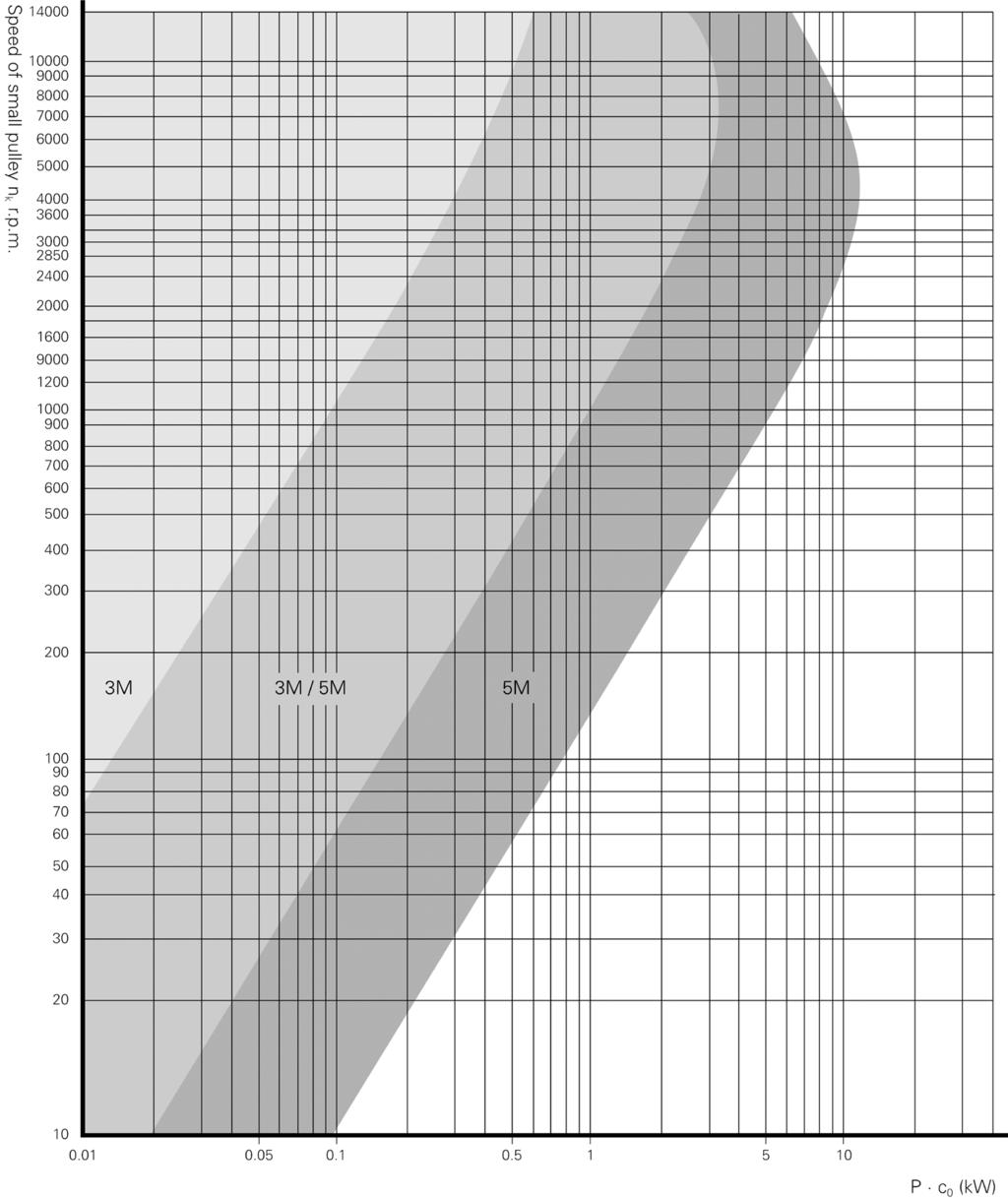
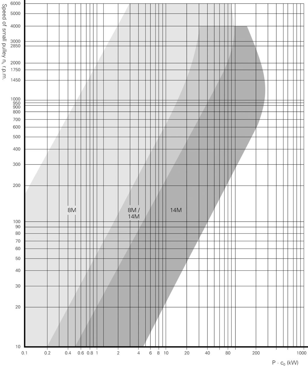
5 Synchronous Drive Belt Width b The synchronous drive belt width b in mm results from the power P to be transmitted, corrected by the overall service factor c o and the power rating P R corrected by the teeth in mesh factor c 1 and the length factor c 5. The following applies to standard belt width: P c o P R c 1 c 5 If P c o > P R c 1 c 5 The next larger standard width should be applied. To obtain a synchronous drive belt width as narrow as possible, the toothed pulleys should be selected as large as possible. This will result in a longer service life at a lower bending load. Overall Service Factor c o The overall service factor c o takes into consideration safety factors for special operating conditions caused by loading conditions, acceleration and fatigue. It is calculated on the basis of the following factors: c o = c 2 + c 3 + c 4 An initial selection is made using the belt graphs based on P. c o and speed of the small pulley. This is then checked against P R.c 1.c 2 P R is taken from the Power Rating Tables. Where the graph offers two possible pitches a check should be made of both. Number of Teeth in Mesh Factor c 1 Ze: 2 = 0.2, 3 = 0.4, 4 = 0.6, 5 = 0.8, 6 = 1.0 Acceleration Factor c 3 Ratio: = 0, 5-4 = 0.1, = 0.2, = 0.3, 3.50 = 0.4 Fatigue Factor c 4 Daily Period of Operation: hours = +0.2, Daily period of operation 16+ hours = +0.4, Additional Belt Deflection (e.g. by means of tensioning rolls): = +0.2, Intermittent operation = 0.2 Length Factor c 5 5M Belt Length L B : <441 = 0.0, = 0.9, = 1.0, = 1.1, >1100 = 8M Belt Length L B : <640 = 0.8, = 0.9, = 1.0, = 1.1, >1799 = 14M Belt Length L B : <1400 = 0.8, = 0.9, = 0.95, = 1.0, = 1.05, >3499 = 1.1 Load Factor c 2 The load factor considers the type of prime mover (driver) and driven machine. Values are reference only. Conveyor Systems : Belt conveyors for light materials Conveyor Systems : Belt conveyors for ore, coal, sand for heavy materials : Elevators, screw conveyors Stirrers : Mixers, liquid Stirrers : Mixers, Semi-liquid Machine Tools: Lathes Machine Tools: For drilling, grinding, milling, planing Brickworks Machinery : Milling machines Brickworks Machinery : Loam mills Textile Machinery : Bobbin winding and warping Textile Machinery : Spinning, twisting and weaving Paper Making : Agitators, calenders, drying Paper Making : Pumps, beaters, pumps, grinders Printing Machinery : Cutting, slitting, folding Printing Machinery : Rotary presses Fans / Blowers : Exhausters, radial blowers Fans / Blowers : Pit ventilators, axial blowers Pumps : Centrifugal and gear pumps Pumps : Reciprocating Generators : Generators and exciters Elevators : Elevators and hoists Centrifuges Mills : Hammer mills Mills : Ball, roller and gravel mills Electric Motors with slow starting torque (up to times the rated torque). Water and steam turbines, internal combustion engines with 8 and more cylinders Electric Motors with high Electric Motors with medium starting torque and braking starting torque ( to 2.5 times the rated torque). torque (more than 2.5 times the rated torque). Internal Internal combustion engines combustion engines up to 4 with 4-6 cylinders cylinders Pre-tension After an initial selection has been made our Technical department would be happy to advise on checking the belt tension and its correct setting. Tension Member Tensile Loading F zul The timing belt is designed correctly when the tension member loading value is not exceeded. Values for each belt can be found on the product page. F u < F zul
6


7 TIMING PULLEYS & BELTS Power Rating 5M 9mm Belt Width 5M 15mm Belt Width


8 TIMING PULLEYS & BELTS 5M 25mm Belt Width 8M 20mm Belt Width Power Rating


9 TIMING PULLEYS & BELTS Power Rating 8M 30mm Belt Width 8M 30mm Belt Width 8M 50mm Belt Width


10 TIMING PULLEYS & BELTS 8M 85mm Belt Width 14M 40mm Belt Width Power Rating


11 TIMING PULLEYS & BELTS Power Rating 14M 55mm Belt Width 14M 85mm Belt Width
Polyflex JB and Micro-V Belt Drive Selection Procedures
 Polyflex JB and Micro-V Belt Drive Selection Procedures How to Design Polyflex JB and Micro-V Belt Drives Note: The upcoming drive selection and engineering sections provide information for Polyflex JB
SIZING AND SELECTION. According to DIN 740 part 2 SIZING
 SIZING SIZING AND SELECTION According to DIN 740 part 2 RW-AMERICA.COM 7 SIZING AND SELECTION SAFETY COUPLINGS ST SYMBOLS T AR = Disengagement torque of the coupling (Nm) K = Service factor T max = Maximum
Linear guide drives. Synchronous shafts The use of synchronous shafts enables several linear axes to be operated with one drive.
 Linear guide drives Drive concept The linear guides are driven via the hollow shaft in the drive head. The drive head is used to directly install a motor or alternatively (in connection with a center shaft)
Shafts Introduction. Shafts 509
 Shafts 509 C H A P T E R 14 Shafts 1. Introduction.. Material Used for Shafts.. Manufacturing of Shafts. 4. Types of Shafts. 5. Standard Sizes of Transmission Shafts. 6. Stresses in Shafts. 7. Maximum
Application basics of operation of three-phase induction motors
 Application basics of operation of three-phase induction motors Design Duty Types Selection Dimensioning Motor Management TM Foreword This technical manual for Three-Phase Induction is the first publication
MECTROL CORPORATION 9 NORTHWESTERN DRIVE, SALEM, NH PHONE FAX TIMING BELT THEORY
 MECTRO CORPORATION 9 NORTHWESTERN DRIVE, SAEM, NH 03079 PHONE 603-890-55 FAX 603-890-66 TIMING BET THEORY Copyright 997, 999, 00 Mectrol Corporation. All rights reserved. April 00 Timing Belt Theory Introduction
Q.1 a) any six of the following 6x2= 12. i) Define - ( Each term 01 mark)
 any six of the following 6x2= 12. i) Define - ( Each term 01 mark)") Important Instructions to examiners: 1) The answers should be examined by key words and not as word-to-word as given in the model answer scheme. 2) The model answer and the answer written by candidate
Important Instructions to examiners: 1) The answers should be examined by key words and not as word-to-word as given in the model answer scheme. 2) The model answer and the answer written by candidate
UNIT 4 FLYWHEEL 4.1 INTRODUCTION 4.2 DYNAMICALLY EQUIVALENT SYSTEM. Structure. Objectives. 4.1 Introduction
 UNIT 4 FLYWHEEL Structure 4.1 Introduction Objectives 4. Dynamically Equivalent System 4.3 Turning Moment Diagram 4.3.1 Turning Moment Diagram of a Single Cylinder 4-storke IC Engine 4.3. Turning Moment
Useful Formulas and Calculations
 Drive Design Speed Ratio = rpm (faster) = PD = N rpm (slower) pd n Where: rpm = Revolutions per minute PD = Larger pitch diameter pd = Smaller pitch diameter N = Larger sprocket grooves n = Smaller sprocket
CHAPTER 17 FLEXIBLE MECHANICAL ELEMENTS LECTURE NOTES DR. HAFTIRMAN
 CHAPTER 17 LEXIBLE MECHANICAL ELEMENTS LECTURE NOTES DR. HATIRMAN lexible Mechanical Elements Belts Roller chains Wire rope lexible shafts lexible Mechanical Elements Belts, ropes, chains, and other similar
Shafts. Fig.(4.1) Dr. Salah Gasim Ahmed YIC 1
 Dr. Salah Gasim Ahmed YIC 1") Shafts. Power transmission shafting Continuous mechanical power is usually transmitted along and etween rotating shafts. The transfer etween shafts is accomplished y gears, elts, chains or other similar
Shafts. Power transmission shafting Continuous mechanical power is usually transmitted along and etween rotating shafts. The transfer etween shafts is accomplished y gears, elts, chains or other similar
E2/20070 ED Design Manual Industrial V-belts. Quad-Power II Super HC MN Hi-Power MN PowerBand Micro-V Polyflex JB
 E2/20070 ED 2003 Design Manual Industrial V-belts Quad-Power II Super HC MN Hi-Power MN PowerBand Micro-V Polyflex JB GATES INDUSTRIAL V-BELT DRIVE DESIGN MANUAL CONTENTS PAGE SECTION PRODUCT FEATURES
UNIT-I (FORCE ANALYSIS)
") DHANALAKSHMI SRINIVASAN INSTITUTE OF RESEACH AND TECHNOLOGY DEPARTMENT OF MECHANICAL ENGINEERING QUESTION BANK ME2302 DYNAMICS OF MACHINERY III YEAR/ V SEMESTER UNIT-I (FORCE ANALYSIS) PART-A (2 marks)
DHANALAKSHMI SRINIVASAN INSTITUTE OF RESEACH AND TECHNOLOGY DEPARTMENT OF MECHANICAL ENGINEERING QUESTION BANK ME2302 DYNAMICS OF MACHINERY III YEAR/ V SEMESTER UNIT-I (FORCE ANALYSIS) PART-A (2 marks)
Members Subjected to Torsional Loads
 Members Subjected to Torsional Loads Torsion of circular shafts Definition of Torsion: Consider a shaft rigidly clamped at one end and twisted at the other end by a torque T = F.d applied in a plane perpendicular
Helical Gears n A Textbook of Machine Design
 1066 n A Textbook of Machine Design C H A P T E R 9 Helical Gears 1. Introduction.. Terms used in Helical Gears. 3. Face Width of Helical Gears. 4. Formative or Equivalent Number of Teeth for Helical Gears.
ENT345 Mechanical Components Design
 1) LOAD AND STRESS ANALYSIS i. Principle stress ii. The maximum shear stress iii. The endurance strength of shaft. 1) Problem 3-71 A countershaft carrying two-v belt pulleys is shown in the figure. Pulley
PRECISION GEARS Spur Gears
 Spur Gears Description Symbol Unit Equation Normal Module m n Transverse Module m t = m n Normal Pressure Angle a n degrees = 2 Transverse Pressure Angle a t degrees = a n Number of Teeth z Profile Shift
Spur Gear Des Mach Elem Mech. Eng. Department Chulalongkorn University
 Spur Gear 10330 Des Mach Elem Mech. Eng. Department Chulalongkorn University Introduction Gear Transmit power, rotation Change torque, rotational speed Change direction of rotation Friction Gear + + Slip
SUMMER 14 EXAMINATION
 Important Instructions to examiners: 1) The answers should be examined by key words and not as word-to-word as given in the model answer scheme. 2) The model answer and the answer written by candidate
SECOND ENGINEER REG. III/2 APPLIED MECHANICS
 SECOND ENGINEER REG. III/2 APPLIED MECHANICS LIST OF TOPICS Static s Friction Kinematics Dynamics Machines Strength of Materials Hydrostatics Hydrodynamics A STATICS 1 Solves problems involving forces
S u p e r T o r q u e Pd
 12 S u p e r T o r q u e Pd No: S4.5M1 mm Width S Super Torque Positive Drive Belt 4.5M 4.5mm Pitch Modified Round Tooth Profile 1 1mm Pitch Length B u i l t F o r S t r e n g t h & E n d u r a n c e Super
S.C. Rulmenti S.A. Barlad Romania Republicii Street No
 SELECTION OF BEARING SIZE Basic load ratings The size of a bearing is selected considering the load in the used rolling bearing and also depends on the operational rating life and prescribed operating
Overview. Dry Friction Wedges Flatbelts Screws Bearings Rolling Resistance
 Friction Chapter 8 Overview Dry Friction Wedges Flatbelts Screws Bearings Rolling Resistance Dry Friction Friction is defined as a force of resistance acting on a body which prevents slipping of the body
ROLLER BEARING FAILURES IN REDUCTION GEAR CAUSED BY INADEQUATE DAMPING BY ELASTIC COUPLINGS FOR LOW ORDER EXCITATIONS
 ROLLER BEARIG FAILURES I REDUCTIO GEAR CAUSED BY IADEQUATE DAMPIG BY ELASTIC COUPLIGS FOR LOW ORDER EXCITATIOS ~by Herbert Roeser, Trans Marine Propulsion Systems, Inc. Seattle Flexible couplings provide
P R E C I S I O N G E A R S Spur Gears
 Spur Gears Description Symbol Unit Equation Normal Module m n Transverse Module m t = m n Normal Pressure Angle α n degrees = 2 Transverse Pressure Angle α t degrees = α n Number of Teeth z Profile Shift
Lesson of Mechanics and Machines done in the 5th A-M, by the teacher Pietro Calicchio. THE GEARS CYLINDRICAL STRAIGHT TEETH GEARS
 MESA PROJECT Lesson of Mechanics and Machines done in the 5th A-M, 2012-2013 by the teacher Pietro Calicchio. THE GEARS To transmit high power are usually used gear wheels. In this case, the transmission
Product description. Compact Modules. Characteristic features. Further highlights
 4 Compact Modules Product description Characteristic features Five fine-tuned sizes based on a compact precision aluminum profile with two integrated pre-tensioned ball rail systems Identical external
 Page 1 of 11 Disclaimer: The information on this page has not been checked by an independent person. Use this information at your own risk. ROYMECH Torque Measurement Complete solutions from 0.02Nm to
Tuesday, February 11, Chapter 3. Load and Stress Analysis. Dr. Mohammad Suliman Abuhaiba, PE
 1 Chapter 3 Load and Stress Analysis 2 Chapter Outline Equilibrium & Free-Body Diagrams Shear Force and Bending Moments in Beams Singularity Functions Stress Cartesian Stress Components Mohr s Circle for
Circular motion minutes. 62 marks. theonlinephysicstutor.com. facebook.com/theonlinephysicstutor Page 1 of 22. Name: Class: Date: Time: Marks:
 Circular motion 2 Name: Class: Date: Time: 67 minutes Marks: 62 marks Comments: Page 1 of 22 1 A lead ball of mass 0.25 kg is swung round on the end of a string so that the ball moves in a horizontal circle
Public Service Commission, West Bengal
 Public Service Commission, West Bengal Syllabus for the Written Test for recruitment to the posts of ASSISTANT ENGINEER (Agri - Mechanical) in West Bengal Service of Agricultural Engineers Mechanical Engineering
NR ROTARY RING TABLE: FLEXIBLE IN EVERY RESPECT
 NR FREELY PROGRAMMABLE ROTARY TABLES NR ROTARY RING TABLE All NR rings allow customer-specific drive motors to be connected NR ROTARY RING TABLE: FLEXIBLE IN EVERY RESPECT WHEN IT S GOT TO BE EXACT We
ENGR 1100 Introduction to Mechanical Engineering
 ENGR 1100 Introduction to Mechanical Engineering Mech. Engineering Objectives Newton s Laws of Motion Free Body Diagram Transmissibility Forces and Moments as vectors Parallel Vectors (addition/subtraction)
Technical Reference Selection calculations Motors Motorized Actuators Cooling Fans Technical Service Life Reference Standard AC Motors
 calculations... H-2 H-2 H Technical Reference H-8 H-28... H-29 AC... H-33... H-0 AC... H-6... H-55... H-58... H-66... H-68... H-77 H- / For Selecting a motor that satisfies the specifications required
DHANALAKSHMI COLLEGE OF ENGINEERING
 DHANALAKSHMI COLLEGE OF ENGINEERING (Dr.VPR Nagar, Manimangalam, Tambaram) Chennai - 601 301 DEPARTMENT OF MECHANICAL ENGINEERING III YEAR MECHANICAL - VI SEMESTER ME 6601 DESIGN OF TRANSMISSION SYSTEMS
SOLUTION (17.3) Known: A simply supported steel shaft is connected to an electric motor with a flexible coupling.
 Known: A simply supported steel shaft is connected to an electric motor with a flexible coupling.") SOLUTION (17.3) Known: A simply supported steel shaft is connected to an electric motor with a flexible coupling. Find: Determine the value of the critical speed of rotation for the shaft. Schematic and
SOLUTION (17.3) Known: A simply supported steel shaft is connected to an electric motor with a flexible coupling. Find: Determine the value of the critical speed of rotation for the shaft. Schematic and
Matlab Sheet 2. Arrays
 Matlab Sheet 2 Arrays 1. a. Create the vector x having 50 logarithmically spaced values starting at 10 and ending at 1000. b. Create the vector x having 20 logarithmically spaced values starting at 10
NATIONAL SENIOR CERTIFICATE GRADE 12
 NTIONL SENIOR ERTIFITE GRE 12 MEHNIL TEHNOLOGY NOVEMER 2017 MRKS: 200 TIME: 3 hours This question paper consists of 15 pages and a 4-page formula sheet. Mechanical Technology 2 E/November 2017 INSTRUTIONS
MECHANICAL ENGINEERING
 MECHANICAL ENGINEERING Paper I Time Allowed: Three Hours Maximum Marks: 200 INSTRUCTIONS Please read each of the following instructions carefully before attempting questions. Candidates should attempt
The principle of the flywheel is found before the many centuries ago in spindle and the potter's wheel.
 TOM Fly Wheel Mechanical Engineering Department The principle of the flywheel is found before the many centuries ago in spindle and the potter's wheel. A heavy-rimmed rotating wheel used to minimize variations
Design And Fabrication Of Groundnut Decorticator
 Design And Fabrication Of Groundnut Decorticator 1 Arjun Vishwakarma, 2 Tejas Tandale, 3 Prof R.H.kekan 1,2 B.E Student (Mechanical Engineering), 3 Assistant professor (Mechanical Engineering) Smt. Kashibai
Dynamics of Machinery
 Dynamics of Machinery Two Mark Questions & Answers Varun B Page 1 Force Analysis 1. Define inertia force. Inertia force is an imaginary force, which when acts upon a rigid body, brings it to an equilibrium
Development and Application of Geneva Mechanism for Bottle Washing.
 American Journal of Engineering Research (AJER) e-issn: 2320-0847 p-issn : 2320-0936 Volume-4, Issue-11, pp-63-73 www.ajer.org Research Paper Open Access Development and Application of Geneva Mechanism
Principles Of Engineering. Part A
 Principles Of Engineering Final Examination Part A Fall 2007 Student Name: Date: Class Period: Total Points: /40 Converted Score: /50 Page 1 of 11 Directions: Circle the letter of the response that best
Automated Spur Gear Designing Using MATLAB
 Kalpa Publications in Engineering Volume 1, 2017, Pages 493 498 ICRISET2017. International Conference on Research and Innovations in Science, Engineering &Technology. Selected Papers in Engineering Automated
LINE TECH Linear Modules. Ready to built-in linear modules with drive
 Ready to built-in linear modules with drive Anodized profile, produced in extrusion molding method Linear rail guiding system (LM3 LM5) Actuation by ball screw, high-helix lead _ screw or toothed belt
Design and Development of an Industrial Centrifuge for Small and Medium Scaled Industries
 Design and Development of an Industrial Centrifuge for Small and Medium Scaled Industries Chukwunonso Nwogu Department of mechanical engineering, Michael Okpara University of Agriculture Umudike P.M.B
Identification system for short product names. Changes/amendments at a glance. 2 Bosch Rexroth AG OBB omega modules R ( )
") Omega Modules OBB 2 OBB omega modules R9990079 (206-05) Identification system for short product names Short product name Example: O B B - 085 - N N - System = Omega module Guideway = Ball Rail System Drive
Omega Modules OBB 2 OBB omega modules R9990079 (206-05) Identification system for short product names Short product name Example: O B B - 085 - N N - System = Omega module Guideway = Ball Rail System Drive
The problem of transmitting a torque or rotary motion from one plane to another is frequently encountered in machine design.
 CHAPER ORSION ORSION orsion refers to the twisting of a structural member when it is loaded by moments/torques that produce rotation about the longitudinal axis of the member he problem of transmitting
ME2302 DYNAMICS OF MACHINERY
 ME2302 DYNAMICS OF MACHINERY TWO MARKS QUESTION AND ANSWERS 1. What are the conditions for a body to be in static and dynamic equilibrium? Necessary and sufficient conditions for static and dynamic equilibrium
PHYA5/2C. (JUN15PHYA52C01) WMP/Jun15/PHYA5/2C/E5. General Certificate of Education Advanced Level Examination June Section B PMT TOTAL
 WMP/Jun15/PHYA5/2C/E5. General Certificate of Education Advanced Level Examination June Section B PMT TOTAL") Centre Number Candidate Number For Examiner s Use Surname Other Names Candidate Signature Examiner s Initials General Certificate of Education Advanced Level Examination June 2015 Question 1 2 Mark Physics
Centre Number Candidate Number For Examiner s Use Surname Other Names Candidate Signature Examiner s Initials General Certificate of Education Advanced Level Examination June 2015 Question 1 2 Mark Physics
the foundation of any business starts here
 the foundation of any business starts here TABLE OF CONTENT The Company... 3 Electric Motors... 4 Gearboxes... 5 Automation Products... 6 Electric Components... 9 Pneumatics... 12 Hydraulics... 13 Handling
2. Polar moment of inertia As stated above, the polar second moment of area, J is defined as. Sample copy
 GATE PATHSHALA - 91. Polar moment of inertia As stated above, the polar second moment of area, is defined as z π r dr 0 R r π R π D For a solid shaft π (6) QP 0 π d Solid shaft π d Hollow shaft, " ( do
BELT TENSION, N & POWER RESULTS CONVEYOR INPUT DATA BELT CONVEYOR NO._ GENERAL ARRANGEMENT METRIC EXAMPLE HEAD DRIVE PRO-BELT MEXPHEAD 1
 13 16 36.576 m 3 SECTIONS @ 30.480 m ARC 131.0 ~ RADIUS 91.440 m 4 36.576 m 24.384 m 62.179 m ~ 436.6 m RADIUS 517.-580 m CONVEYOR INPUT DATA BELT WIDTH. mm = 1600 C.AP ACITY, Mtph = 2200 DENSITY. kg/m"3
CLUTCHES AND BRAKES. Square-jaw clutch
 Clutches: CLUTCHES AND BRAKES A Clutch is a mechanical device which is used to connect or disconnect the source of power from the remaining parts so the power transmission system at the will of the operator.
Lecture 3: Electrical Power and Energy
 Lecture 3: Electrical Power and Energy Recall from Lecture 2 E (V) I R E Voltage Similar to water pressure Unit: Volts (V) I Current Similar to water flow Unit: Amperes (A) R Resistance Similar to water
UNIT 3 Friction and Belt Drives 06ME54. Structure
 UNIT 3 Friction and Belt Drives 06ME54 Structure Definitions Types of Friction Laws of friction Friction in Pivot and Collar Bearings Belt Drives Flat Belt Drives Ratio of Belt Tensions Centrifugal Tension
Technical Information/ Calculation methods
 flat belts Technical Information/ Calculation methods Contents Technical information Top surface/ friction coating Tension member Friction coating Lines 1 Types 2 Properties 2 Storage 2 Availability, standard
Analysis of bending strength of bevel gear by FEM
 Analysis of bending strength of bevel gear by FEM Abhijeet.V. Patil 1, V. R. Gambhire 2, P. J. Patil 3 1 Assistant Prof., Mechanical Engineering Dept.,ADCET,Ashta.. 2 Prof., Mechanical Engineering Dept.,TKIET,
HORIZONTAL FEED DRIVES IN HEAVY DUTY MACHINES TOOLS
 Proceedings in Manufacturing Systems, Volume 12, Issue 1, 2017, 3 8 ISSN 2067-9238 HORIZONTAL FEED DRIVES IN HEAVY DUTY MACHINES TOOLS Dan PRODAN 1,*, George CONSTANTIN 2, Anca BUCUREȘTEANU 3 1, 2, 3)
2014 MECHANICS OF MATERIALS
 R10 SET - 1 II. Tech I Semester Regular Examinations, March 2014 MEHNIS OF MTERILS (ivil Engineering) Time: 3 hours Max. Marks: 75 nswer any FIVE Questions ll Questions carry Equal Marks ~~~~~~~~~~~~~~~~~~~~~~~~~
The basic dynamic load rating C is a statistical number and it is based on 90% of the bearings surviving 50 km of travel carrying the full load.
 Technical data Load Rating & Life Under normal conditions, the linear rail system can be damaged by metal fatigue as the result of repeated stress. The repeated stress causes flaking of the raceways and
Stress Analysis Lecture 3 ME 276 Spring Dr./ Ahmed Mohamed Nagib Elmekawy
 Stress Analysis Lecture 3 ME 276 Spring 2017-2018 Dr./ Ahmed Mohamed Nagib Elmekawy Axial Stress 2 Beam under the action of two tensile forces 3 Beam under the action of two tensile forces 4 Shear Stress
Servo Motor Selection Flow Chart
 Servo otor Selection Flow Chart START Selection Has the machine Been Selected? YES NO Explanation etermine the size, mass, coefficient of References friction, and external forces of all the moving part
XR Series. Introduction. Design Features. Availability. Applications
 Kaydon Bearings Slewing Ring Bearings Catalog 390 Introduction The consists of Kaydon cross roller bearings. They provide a high degree of stiffness and low rotational torque within a minimal envelope.
SAMCEF For ROTORS. Chapter 1 : Physical Aspects of rotor dynamics. This document is the property of SAMTECH S.A. MEF A, Page 1
 SAMCEF For ROTORS Chapter 1 : Physical Aspects of rotor dynamics This document is the property of SAMTECH S.A. MEF 101-01-A, Page 1 Table of Contents rotor dynamics Introduction Rotating parts Gyroscopic
Mechanical Design. Design of Shaft
 Mechanical Design Design of Shaft Outline Practical information Shaft design Definition of shaft? It is a rotating member, in general, has a circular cross-section and is used to transmit power. The shaft
Mechanical Principles
 Unit 4: Mechanical Principles Unit code: F/601/1450 QCF level: 5 Credit value: 15 Aim This unit aims to develop learners understanding of an extended range of mechanical principles that underpin the design
Precision Ball Screw/Spline
 58-2E Models BNS-A, BNS, NS-A and NS Seal Outer ring Shim plate Seal Spline nut Seal Collar Shim plate Seal End cap Ball Outer ring Ball screw nut Outer ring Ball Retainer Retainer Outer ring Point of
SERVOMOTOR SIZING AND APPLICATION. Gary Kirckof, P.E.
 SERVOMOTOR SIZING AND APPLICATION by Gary Kirckof, P.E. Basic Contents About the Author xvii Introduction xix 1 Kinematics 1 Introduction 1 Rectilinear Motion 2 Position and Distance 2 Velocity and Speed
Front flange FLV. Max. [knm/stroke]
![Front flange FLV. Max. [knm/stroke]](/thumbs/92/109382839.jpg "Front flange FLV. Max. [knm/stroke]") SDN 45 Safety shock absorbers SDN are a low cost alternative to industrial shock absorbers appropriate to customers requirements. Typical applications: cranes, storage and retrieval unit for highbay warehouse,
SDN 45 Safety shock absorbers SDN are a low cost alternative to industrial shock absorbers appropriate to customers requirements. Typical applications: cranes, storage and retrieval unit for highbay warehouse,
TSCHAN S US Elastische Kupplungen Flexible Couplings TNS Flexible Couplings. Partner for Performance
 US 11 2015 TSCHAN S Elastische Kupplungen Flexible Couplings TNS Flexible Couplings Partner for Performance www.ringfeder.com Welcome to your system supplier for every aspect of power transmission Today
High-Performance Universal Joint Shafts
 High-Performance Universal Joint Shafts Fair. Reliable. Innovative. This is our promise to our customers. And it is the demand we place on ourselves in the Paper, Energy, Mobility and Service markets.
Flexible Mechanical Elements
 lexible Mechanical Elements INTRODUCTION Belts, ropes, chains, and other similar elastic or flexible machine elements are used in conveying systems and in the transmission of power over comparatively long
HPG xxx 030 C1 C2 C3. High performance angle gearboxes. Output. Input. Drawings. C with option motor flange. View x. Centering View y.
 HPG 030 1 2 3 Input Output 1 View M6 ( deep) 0 Ø4 H (2.2 deep) 18.0 M6 ( deep) 0 2 3 M6 ( deep) 2 13.0 4 2.0 18.0 24.0 M Ø12 k6 6 M6 ( deep) M6 ( deep) 3 Eample HPG 030 2 with option motor flange 0 M6
Technical Guide for Servo Motor Selection
 Technical Guide for Servo otor Selection CS_Servo Selection_TG_E_3_1 Servo otor Selection Software Use your PC to select a Servo otor "otor Selection Program for Windows" o you always feel "Calculation
Revision Term 2. Prof Ahmed Kovacevic
 ME 1110 Engineering Practice 1 Engineering Drawing and Design - Lecture 20 Revision Term 2 Prof Ahmed Kovacevic School of Engineering and Mathematical Sciences Room CG25, Phone: 8780, E-Mail: a.kovacevic@city.ac.uk
DEPARTMENT OF MECHANICAL ENGINEERING Dynamics of Machinery. Submitted
 DEPARTMENT OF MECHANICAL ENGINEERING Dynamics of Machinery Submitted 1 UNIT I - Force Analysis INDEX (1) Introduction (2) Newton s Law (3) Types of force Analysis (4) Principle of Super Position (5) Free
Principles of Engineering Midterm Exam
 Principles of Engineering Midterm Exam Instructions: Respond to all questions below by circling the correct answer, or by writing your answer in the blank space. Use a dark pen/pencil and write neatly
Design of Mechanical Drives for a Parabolic Radio Antenna
 Design of Mechanical Drives for a Parabolic Radio Antenna Akshaya Kulkarni 1, Kunal Bhandari 1, Pranoti Panchwagh 1 Department of Mechanical Engineering,VIIT, Savitribai Phule Pune University, Ganeshkhind,
MEMS Project 2 Assignment. Design of a Shaft to Transmit Torque Between Two Pulleys
 MEMS 029 Project 2 Assignment Design of a Shaft to Transmit Torque Between Two Pulleys Date: February 5, 206 Instructor: Dr. Stephen Ludwick Product Definition Shafts are incredibly important in order
MSBCCL Series Asynchronous Three-Phase Brake Motors With Squirrel Cage Rotor Direct Current Brake
 NEMA MOTOR GOST MOTOR IEC MOTOR MSBCCL Series Asynchronous Three-Phase Motors ith Squirrel Cage Rotor Direct Current PUMP D.C. MOTOR GENERATOR MSBCCL series-enclosed construction externally ventilated-sizes
APPENDIX. SELECTING THE SureServo SERVO SYSTEM. In This Appendix... Selecting the SureServo Servo System...B 2. Leadscrew - Example Calculations...
 SELECTING THE SureServo SERVO SYSTEM APPENDIX B In This Appendix... Selecting the SureServo Servo System............B 2 The Selection Procedure......................................B 2 How many pulses
NATIONAL CERTIFICATE (VOCATIONAL) APPLIED ENGINEERING TECHNOLOGY NQF LEVEL 4 NOVEMBER 2009
 APPLIED ENGINEERING TECHNOLOGY NQF LEVEL 4 NOVEMBER 2009") NATIONAL CERTIFICATE (VOCATIONAL) APPLIED ENGINEERING TECHNOLOGY NQF LEVEL 4 NOVEMBER 2009 (6021024) 30 October (Y-Paper) 13:00 16:00 A non-programmable scientific calculator may be used. This question
NATIONAL CERTIFICATE (VOCATIONAL) APPLIED ENGINEERING TECHNOLOGY NQF LEVEL 4 NOVEMBER 2009 (6021024) 30 October (Y-Paper) 13:00 16:00 A non-programmable scientific calculator may be used. This question
Chapter 3. Load and Stress Analysis. Lecture Slides
 Lecture Slides Chapter 3 Load and Stress Analysis 2015 by McGraw Hill Education. This is proprietary material solely for authorized instructor use. Not authorized for sale or distribution in any manner.
Hidden Potential between the Crankshaft and Valves
 318 319 Hidden Potential between the Crankshaft and Valves W U U M P I Z R W O U Z T W H N E D K U N W P O N C A L E R U I N K O P J E W L S P N Z A D F T O I From E O H the O I optimization O O A N G
Automobile manual transmission
 Design of Shaft A shaft is a rotating member usually of circular crosssection (soli or hollow), which is use to transmit power an rotational motion. Axles are non rotating member. Elements such as gears,
Exam 3 PREP Chapters 6, 7, 8
 PHY241 - General Physics I Dr. Carlson, Fall 2013 Prep Exam 3 PREP Chapters 6, 7, 8 Name TRUE/FALSE. Write 'T' if the statement is true and 'F' if the statement is false. 1) Astronauts in orbiting satellites
CHAPTER 8 SCREWS, FASTENERS, NONPERMANENT JOINTS
 CHAPTER 8 SCREWS, FASTENERS, NONPERMANENT JOINTS This chapter deals with the design and analysis of nonpermanent fasteners such as bolts, power screws, cap screws, setscrews, eys and pins. 8- Standards
Replacement of Grid Coupling with Bush Pin Coupling in Blower
 Replacement of Grid Coupling with Bush Pin Coupling in Blower Ramees Rahman A 1, Dr S Sankar 2 Dr K S Senthil Kumar 3 P.G. Student, Department of Mechanical Engineering, NCERC, Thrissure, Kerala, India
High Performance Composite V-Belts
 High Performance Composite V-Belts 2 More Power for Tough Drives Easy to use twist-lock design The everyday industrial workhorse Perfectly suited to Z/10, A/13, B/17, C/22 and D/32 drives Fast fit T-Link
UNIVERSITY OF SASKATCHEWAN Department of Physics and Engineering Physics
 UNIVERSITY OF SASKATCHEWAN Department of Physics and Engineering Physics Physics 115.3 Physics and the Universe FINAL EXAMINATION December 14, 013 NAME: (Last) Please Print (Given) Time: 3 hours STUDENT
Dimensions of propulsion shafts and their permissible torsional vibration stresses
 (Feb 2005) (orr.1 Mar 2012) (orr.2 Nov 2012) Dimensions of propulsion shafts and their permissible torsional vibration stresses.1 Scope This UR applies to propulsion shafts such as intermediate and propeller
Applied Electronics and Electrical Machines
 School of Electrical and Computer Engineering Applied Electronics and Electrical Machines (ELEC 365) Fall 2015 DC Machines 1 DC Machines Key educational goals: Develop the basic principle of operation
Selection Calculations For Linear & Rotary Actuators
 H-8 For Electric Linear Slides and Electric Cylinders First determine your series, then select your product. Select the actuator that you will use based on the following flow charts: Selection Procedure
CHAPTER 24 SIMPLE MACHINES
 CHAPTER 24 SIMPLE MACHINES EXERCISE 106, Page 240 1. A simple machine raises a load of 825 N through a distance of 0.3 m. The effort is 250 N and moves through a distance of 3.3 m. Determine: (a) the,
A nonlinear dynamic vibration model of defective bearings: The importance of modelling the finite size of rolling elements
 A nonlinear dynamic vibration model of defective bearings: The importance of modelling the finite size of rolling elements Alireza Moazenahmadi, Dick Petersen and Carl Howard School of Mechanical Engineering,
Department of Mechanical FTC College of Engineering & Research, Sangola (Maharashtra), India.
, India.") VALIDATION OF VIBRATION ANALYSIS OF ROTATING SHAFT WITH LONGITUDINAL CRACK 1 S. A. Todkar, 2 M. D. Patil, 3 S. K. Narale, 4 K. P. Patil 1,2,3,4 Department of Mechanical FTC College of Engineering & Research,
VALIDATION OF VIBRATION ANALYSIS OF ROTATING SHAFT WITH LONGITUDINAL CRACK 1 S. A. Todkar, 2 M. D. Patil, 3 S. K. Narale, 4 K. P. Patil 1,2,3,4 Department of Mechanical FTC College of Engineering & Research,
THEORY OF MACHINES I
 THEORY OF MACHINES I (Kinematics of Machines) (In SI Units) For BE/B.Tech. 3rd YEAR (Strictly as per the latest syllabus prescribed by U.P.T.U., U.P.) By Dr. R.K. BANSAL B.Sc. Engg. (Mech.), M.Tech., Hons.
Selecting the SureStep Stepping System...C 2
 SELECTING THE SureStep STEPPING SYSTEM APPENDIX C In This Appendix... Selecting the SureStep Stepping System.............C 2 The Selection Procedure..............................C 2 How many pulses from