H a r m o n i c P l a n e t a r y
|
|
|
- Lucas Norton
- 5 years ago
- Views:
Transcription

1 H a r m o n i c P l a n e t a r y HPG Series Planetary Gearhead Total Motion Control P r e c i s i o n G e a r i n g & M o t i o n C o n t r o l
2 Harmonic Drive LLC is the world s largest manufacturer of harmonic drive gearing and motion control systems, with an installed base of over 4 million products worldwide. Known for its high precision, zero backlash harmonic drive products, Harmonic Drive LLC was a pioneer in developing high precision mechanical drive products to complement the growing use of high accuracy servo and stepper motors in motion control. With its new, unique Harmonic Planetary gearhead, Harmonic Drive LLC continues to lead the way in innovative, precision motion products. The NEW Harmonic Planetary Low Backlash For Life The new Harmonic Planetary gearhead is a revolutionary new design in planetary gearheads. The innovative Ring Gear automatically adjusts for backlash, ensuring consistent, low backlash for the life of the gearhead. Harmonic Drive LLC s experience in designing and producing harmonic drive gears was used to design a unique ring gear. This ring gear acts as a backlash buffer, as it automatically provides the optimum backlash in the planetary gear train. As compared to other planetary designs, where gear wear increases backlash over time, the Harmonic Planetary maintains the same low backlash for the life of the gearhead. The design engineer is ensured of consistently low backlash, without the annoying backlash creep of other designs. Harmonic Drive LLC products are used everywhere precision motion is needed, including semiconductor equipment, robotics, and even space applications. All Harmonic Drive LLC products are produced in the company s 150,000 square foot, ultra-modern facility in Nagano, Japan. The facility is ISO 9001 certified. Complete application engineering, custom design, customer service, and technical support are provided in the United States at its technical centers in Peabody, Massachussettes and Hauppauge, New York. Harmonic Drive LLC
3 Contents HPG Series Harmonic Planetary Gear System Components Principle of Operation Application Examples Rating Table How to use the Rating Table Dimensions Accuracy Definitions Accuracy Data Torsional Stiffness No-load Starting Torque No-load Back Driving Torque No-load Running Torque Efficiency Motor Assembly Assembly of the Housing and Output Flange Lubrication Performance Data for the Output Bearing Calculation of the Permissible Static Tilting Moment Output Bearing Life Life of Output Bearing for Oscillating Motion Output Bearing Tolerances Selection Procedure Selection Example Ordering Code


4 HPG Series Harmonic Planetary Gears The outstanding feature of the new HPG series precision planetary gears is the innovative ring-gear. This is the result of Harmonic Drive LLC s engineering and manufacturing know-how. By using a new ring-gear design, the planetary gears achieve a backlash level of less than 3 arc-min without requiring an additional backlash adjustment mechanism. In addition, a backlash level of less than 1 arc-min is available as an option. Until now highly accurate gears and an additional adjustment mechanism were necessary to minimize backlash. Tight gear engagement for conventional planetary gears leads to torque ripple and an increase in of noise and wear. To avoid this problem the new HPG series features a unique internally toothed ring-gear, thereby exploiting many years of Harmonic Drive LLC experience. The ring-gear ensures that backlash is minimized and that all planet gears share the load equally. Backlash less than 1 arc-min By using an innovative ring-gear, backlash of less than 1 arc-min can be achieved without requiring an additional backlash adjustment mechanism. High moment stiffness The very compact and very stiff cross-roller output bearing provides the planetary gears with a high moment stiffness and excellent running tolerances at the output flange. High efficiency As a result of the optimized tooth profile efficiencies of more than 90 % can be achieved. Repeatability better than 20 arc-sec The highly precise components and the automatic backlash compensation mechanism afforded by the ring gear design provide a repeatability better than ±20 arc-sec. Easy motor assembly The supported motor shaft coupling and the variable adapter flange guarantee an extremely rapid and easy motor assembly. Reduction ratios between 3:1 and 45:1 A selection of reduction ratios (3:1, 11:1, 21:1, 33:1 and 45:1) allows a wide range of output torque and speed. Flange or Shaft Output Configuration The HPG is available in either configuration to provide convenient methods to attach the output load. 4

5 System Components Input coupling Ring gear One piece: Inner ring of cross-roller bearing, carrier of the second stage, and output flange. Fig. 1 5
 2 double stage for i=11, 22, 33, 45 For double-stage HPG gears the sun gear of the first-stage planetary gear is connected to the motor shaft.")
6 Principle of Operation Fig. 2 1 single stage for i=3 and i=5 (only second stage) 2 double stage for i=11, 22, 33, 45 For double-stage HPG gears the sun gear of the first-stage planetary gear is connected to the motor shaft. The input torque from the motor is transmitted to three equally spaced planet gears. The ring gear is common to both gear stages. The carrier of the first stage is connected to the fully floating sun gear of the second planetary stage. This also features three equally spaced planet gears, which engage with the deformable region of the ring gear. The carrier of the second stage, which acts as output element, is integrated with the flange and inner ring of the output-side cross roller bearing. The direction of rotation of the input shaft and output flange/shaft are the same. For single-stage HPG gears the complete first stage as described above is absent and the sun gear of the second stage is connected directly to the motor shaft. 6


7 Application Examples Linear axis for robots Loading and unloading equipment Fig. 3 Fig. 4 Primary axes of scara robots Wafer handling robots Fig. 5 Fig. 6 7
8 Rating Table Size Gear Ratio Rated Torque at 3000rpm *1 Max.Average load Torque *2 Repeated Peak Torque*3 Max.Momentary Torque *4 Limit for Average Input Speed *5 Max. Input Speed *6 Moment of Inertia *7 Weight *8 N.m In.lb N.m In.lb N.m In.lb N.m In.lb r/min r/min Gear heads w/output Input Shaft Type w/output Gear heads w/ Output Input Shaft Type w/output Shaft X 10-4 kg.m2 Flange X 10-4 kg.m2 Shaft X 10-4 kg.m2 Flange X 10-4 kg.m2 Shaft kgf Flange kgf Shaft kgf Flange kgf (42) *9 28 (27) *9 18 (32) * (18) * (17) * (7.1) *9 6.5 (47) * (6.5) *9 6.1 Contact Harmonic Drive LLC for additional sizes and gear ratios Please note: *1: Output torque set based on the life of L10=20000 hours when Input speed is 3000 rpm, which is the rated rotational speed of ordinary servo motors. Input speed for Models 50 and 65 are set at rpm. *2: A maximum tolerance of average load torque calculated based on a load torque pattern. A life of 2000 hours or more is a critarion when operate at an Input speed of 2000 rpm. *3: Maximum tolerance of torque applied on start and stop in operation cycles.*4: Maximum tolerance for shock torque in an emergency stop and for external shock torque. Always operate within these ranges. Calculate permissible frequency in model selection and check whether or not they meet operating conditions. *5: Maximum permissible Input speed in operation modes other than continuous operation. *6: It depends on the operating environment and a driving condition, but it is the permissible scale for the continuous operation and the operating pattern of the average Input speed. It is limited in the terms of heat generated in the reduction gears. *7: The value indicated including the input shaft coupling, the motor flange and other parts. *8: Weight for gear with standard motor flange and coupling. How to use the Rating Table 8 1Nm = 8.85in-lbs Limit for Average Torque (T A ) - Load Limit 1 When a gear is used under a variable load, an average torque should be calculated for the complete operating cycle, (see equation 15, page 21). The value calculated should not exceed the limit T A given in the rating table. Otherwise the performance and life of the gear may be impaired. Limit for Repeated Peak Torque (T R ) - Load Limit 2 This is the allowable output torque that can be developed during acceleration or deceleration. The peak torque that occurs during starting or stopping can be calculated if the load moment of inertia and acceleration (or deceleration) time are known. This torque limit must not be exceeded during the normal operating cycle. Limit for Momentary Peak Torque (T M ) - Load Limit 3 The gear may be subjected to momentary peak torques in the event of a collison or emergency stop. The magnitude and frequency of occurrence of such peak torques must be kept to a minimum and they should under no circumstance occur during the normal operating cycle, (see equation 22, page 21).


9 Dimensions Fig. 7 HPG-14A Dimensions A, B, C, D, E, F, G, H depend on the chosen motor/adapter flange combination. Contact Harmonic Drive LLC for details. Fig. 8 HPG-20A Dimensions A, B, C, D, E, F, G, H depend on the chosen motor/adapter flange combination. Contact Harmonic Drive LLC for details. 9


10 Dimensions Fig. 9 HPG-32A Dimensions A, B, C, D, E, F, G, H depend on the chosen motor/adapter flange combination. Contact Harmonic Drive LLC for details. Fig. 10 HPG-50A Dimensions A, B, C, D, E, F, G, H depend on the chosen motor/adapter flange combination. Contact Harmonic Drive LLC for details. 10

 ϕ 1 The repeatability of the gear describes the position difference measured during repeated movement to the same desired position from the same direction.")
 Fig.")
11 Fig. 11 Hysteresis Loss/Backlash (description via hysteresis curve) When a torque is applied to the output of a Harmonic Planetary Gear HPG with the input rotationally locked, the torque-torsion relationship measured at the output typically follows the hysteresis curve 0-A-B-A - B -A, as shown in Fig. 11. The value of the displacement B-B is defined as the hysteresis loss or backlash. T N : Rated output torque ϕ : Output rotation angle Fig. 12 Repeatability (linear representation) ϕ 1 The repeatability of the gear describes the position difference measured during repeated movement to the same desired position from the same direction. The repeatability is defined as half the value of the maximum difference measured, preceded by a ± sign, as shown in Fig. 12. ϕ 2 ϕ 7 x x / 2 x / 2 Repeatability = ± x /2 Transmission Accuracy (linear representation) Fig. 13 Accuracy Transmission Accuracy Output angle Accuracy Definitions The transmission accuracy of the gear represents a linearity error between input and output angle. The transmission accuracy is measured for one complete output revolution using a high resolution measurement system. The measurements are carried out without direction reversal. The transmission accuracy is defined as the sum of the maximum positive and negative differences between theoretical and actual output rotation angle, as shown in Fig. 13. Table 2 Accuracy of HPG Harmonic Planetary Gears Size Hysteresis Loss Backlash Repeatability Transmission Accuracy [arc min] [arc sec] [arc min] Standard Optional BL3 BL < + 20 < < + 15 < < + 15 < 4 Accuracy Data < + 15 < 4 11

![14 Table 3 Size A Torsional Stiffness = B [Nm/min] [Nm/rad] D [arc-min] Backlash Class BL3 BL1 i = 5 i > 5 i = 5 i > 5 14 1.4 20 5.4 32 22.0 50 66.6 4700 18500 74100 230000 2.2 1.5 1.3 1.3 2.](/docs-images/96/128789620/images/12-2.jpg "7 2.0 1.7 1.7 1.1 0.6 0.5 0.5 1.7 1.1 1.0 1.0 A B : Torsional stiffness T N : Rated Torque; Tab.1 D: Average torsion angle at 0.")
12 Torsional Stiffness The torsional stiffness may be evaluated by means of the torque-torsion curve shown in Fig. 14. The values quoted in table 3 are the average of measurements made during numerous tests. Fig. 14 Table 3 Size A Torsional Stiffness = B [Nm/min] [Nm/rad] D [arc-min] Backlash Class BL3 BL1 i = 5 i > 5 i = 5 i > A B : Torsional stiffness T N : Rated Torque; Tab.1 D: Average torsion angle at 0.15 x T N ϕ: Output rotation angle Calculation of the torsion angle ϕ at load torque T ( T - T L ) ϕ = D + A B [Equation 1] ( ) D : [min] (Fig. 14) T : Load torque [Nm] 12 T L : T N x 0,15 [Nm] A : Torsional stiffness [Nm/min] ; Tab. 3 B
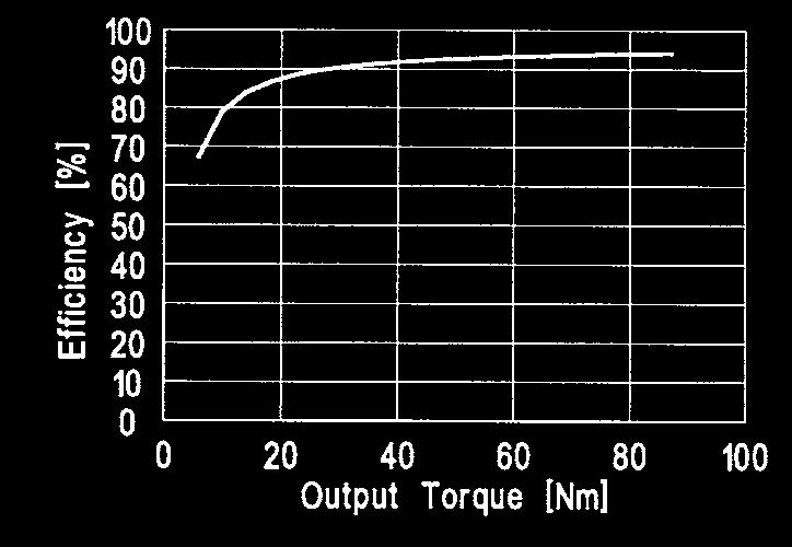
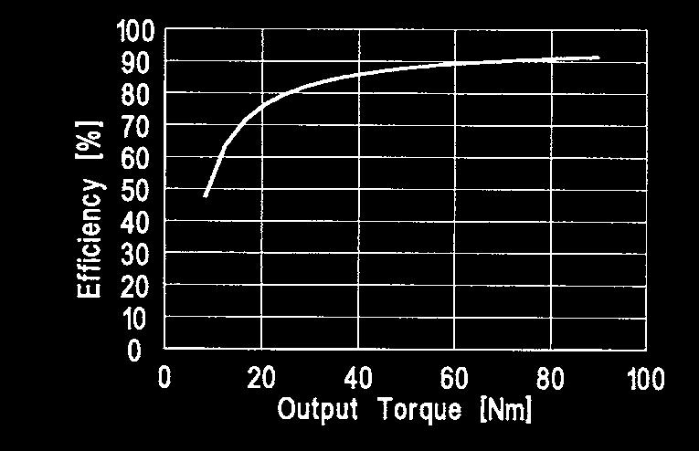
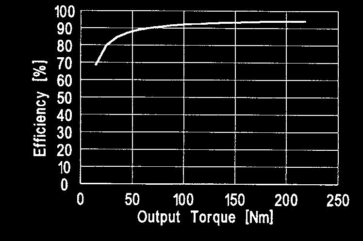
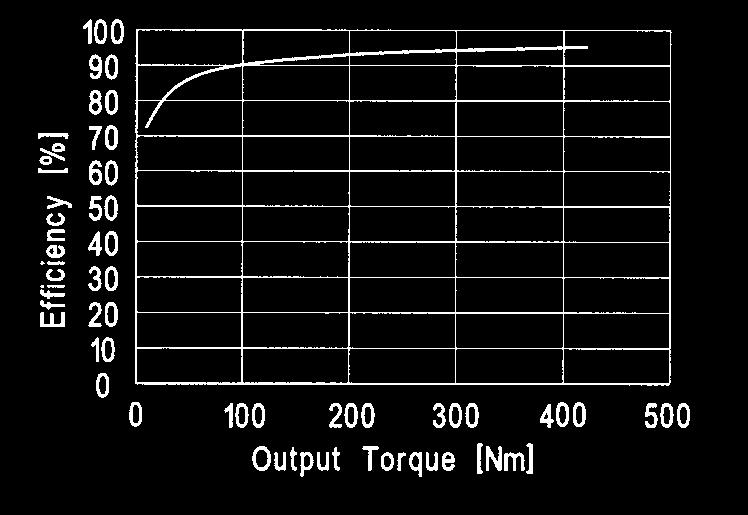
13 No-load Starting Torque, Back Driving Torque, Running Torque Table 4 Size Ratio No-load starting torque Ncm No-load back driving torque Ncm No-load* running torque at 3000 rpm Ncm All values refer to a gear at an operating temperature of +25 C. * For Backlash Class BL1 the values increased by 20%. The efficiency curves are mean values, which are valid for the following conditions: Input Speed: n = 3000 rpm Ambient Temperature: 25 C Lubrication: Size 14A~32A - Grease SK-2 Size 50A - EPNOC AP(N)2 Backlash Class: BL3 (for BL1 efficiency approx. 2% lower) No-load Starting Torque The no-load starting torque is the quasistatic torque required to commence rotation of the input element (high speed side) with no load applied to the output element (low speed side), see Table 4. No-load Back Driving Torque The no-load back driving torque is the torque required to commence rotation of the output element (low speed side) with no load applied to the input element (high speed side). The approximate range for no-load back driving torque, based on tests of actual production gears, is shown in Table 4. In no case should the values given be regarded as a margin in a system that must hold an external load. A brake must be used where back driving is not permissible. No-load Running Torque The no-load running torque is the torque required to maintain rotation of the input element (high speed side) at a defined input speed with no load applied. Efficiency In case of an ambient temperature below 25 C the efficiency η T can be determined using equation 2, and figure 15. Efficiency η is found from figures 16~19. η T = η K [Equation 2] Fig
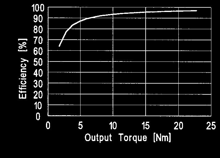
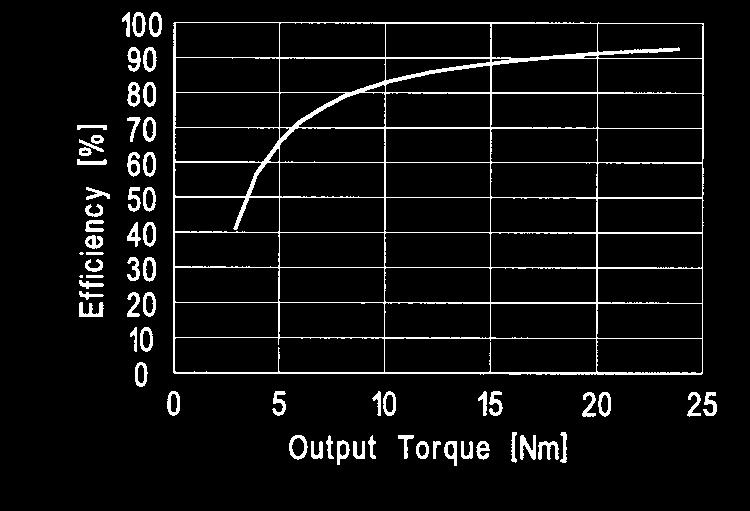
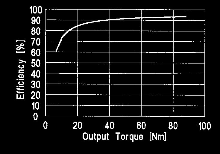
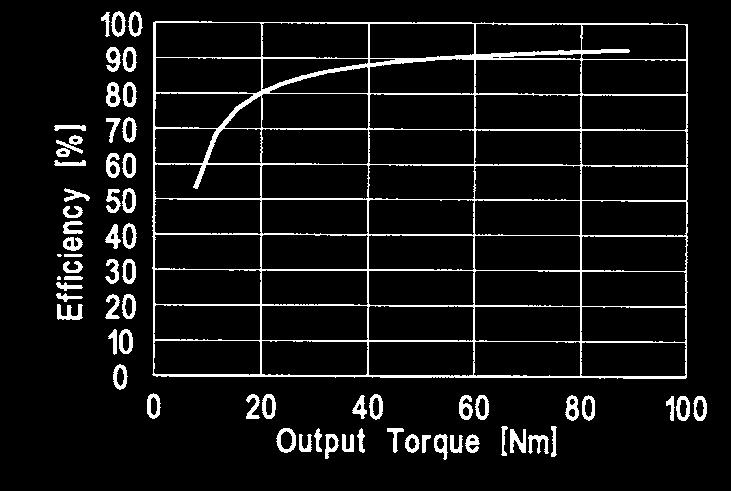
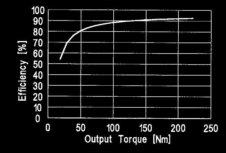
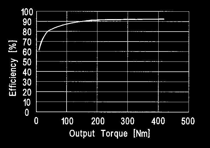
14 Efficiency Size 14 Fig. 16 Size 20 Fig. 17 Ratio = 3 & 5 Ratio = 3 & 5 Ratio = 11 Ratio = 11 Ratio = 21 Ratio = 21 Ratio = 33, 45 Ratio = 33, 45 14

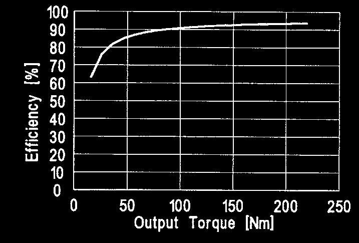
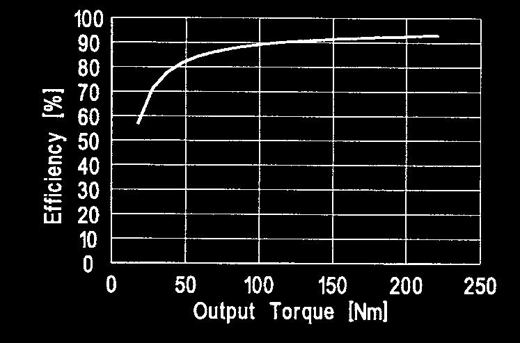
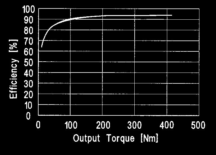
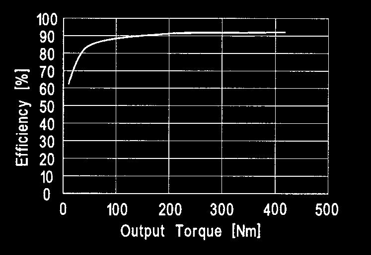
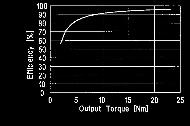
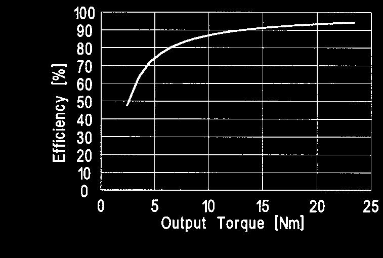
15 Efficiency Size 32 Fig. 18 Size 50 Fig. 19 Ratio = 3 & 5 Ratio = 3 & 5 Ratio = 11 Ratio = 11 Ratio = 21 Ratio = 21 Ratio = 33, 45 Ratio = 33, 45 15
16 Motor Assembly To connect a motor to a HPG Series gear please follow the following instructions: 1 Turn the coupling on the input side so that the head of the bolt aligns with the bore for the rubber cap. 2 Apply Loctite 515 (or equiv.) sealant on mating surface of Gearhead adapter. 3 Gently insert the motor into the gear. 4 Fix the motor and gear by tightening the bolts on the flange (see Table 5). 5 Fasten the bolt on the input coupling (see Table 6). 6 Finally, insert the rubber cap provided. Table 5 4 Fig. 20 Bolt Size Tightening Torque [Nm] M3 M4 M5 M6 M8 M10 M Table 6 5 Bolt Size M3 M4 M5 M6 M8 Tightening Torque [Nm] Assembly of the Housing and Output Flange Fig. 21 Assembly of the Housing When installing the HPG in a machine, please ensure that the assembly surfaces are flat and the tapped holes are free of burrs. Table 7 Size HPG-14A HPG-20A HPG-32A HPG-50A Number of Bolts Bolt Size Bolt pitch diameter [mm] Tightening Torque [Nm] Torque transmitting capacity [Nm] M5 M8 M10 M Assembly of the Output Flange When connecting the load to the output flange please observe the specifications for the output bearing given on page 17. Table 8 Size HPG-14A HPG-20A HPG-32A HPG-50A Number of Bolts Bolt Size Bolt pitch diameter [mm] Tightening Torque [Nm] Torque transmitting capacity [Nm] M4 M6 M8 M Please note: The flange is sealed against oil leakage. It is therefore not necessary to apply additional sealing liquid. 16 Lubrication HPG Planetary Gears are delivered grease-packed. An additional grease lubrication is not necessary, either during assembly or during operation. Applied lubricant: 14A~32A: Harmonic Drive Grease type SK-2. 50A: EPNOC AP(N)2 Nippon Oil Company Ambient temperature range: -10 C up to +40 C. Maximum operating temperature: + 80 C


 Static Tilting Moment Tilting Moment Stiffness Permissible 1) Dynamic Axial Load")
17 Performance Data for the Output Bearing HPG Planetary Gears incorporate a high stiffness cross-roller bearing to support output loads. This specially developed bearing can withstand high axial and radial forces as well as high tilting moments. The reduction gear is thus protected from external loads, enabling a long service life and consistent performance. The integration of an output bearing also serves to reduce subsequent design and production costs, by removing the need for additional output bearings in most applications. Furthermore, installation and assembly of the reduction gear is greatly simplified. Table 9 lists ratings and important dimensions for the output bearings. Size Pitch Circle Offset Dynamic Load Rating Stating Load Rating Permissible Dynamic Tilting Moment Permissible 2) Static Tilting Moment Tilting Moment Stiffness Permissible 1) Dynamic Axial Load Permissible 1) Dynamic Radial Load Permissible 3) Static Axial Load Table 9 Permissible 3) Static Radial Load ø d p [m] R [m] C [N] C 0 [N] M [Nm] M 0 [Nm] K B [Nm/arc min] F a [N] F r [N] F a [N] F r [N] ) These values are valid for the following conditions: These values correspond to a static safety factor f s = 1.5. For other values of f s please refer to equations on page For F a : M = 0; F r = 0 F r : M = 0; F a = 0 n =140 rpm L 10 = h f w = M γ = K B [Equation 3] γ [arc min] M [Nm] K B [Nm/min] The angle of inclination of the output flange as a function of the tilting moment acting on the output bearing, can be calculated by means of equation 3: with: = Angle of inclination of the output flange = Tilting moment acting on the output bearing = Moment stiffness of the output bearing Fig. 22 C 0 2M d p f S = with P 0 = x 0 ( F r + ) + Y 0. F a P 0 and so Equation 4] d p C 0 M 0 = 2 f S [Equation 5] Calculation of the Permissible Static Tilting Moment In case of static load, the bearing load capacity can be determined as follows: Table 10 Rotation Conditions of Bearing Normal Impacts Vibrations High Positioning Accuracy Lower limit value for f s > 1.5 > 2 > 2 > 3 f s = Static load safety factor (f s = ) (Tab. 10) C 0 = Static load rating (Tab. 9) x 0 = 1 y 0 = 0.44 P 0 = Static equivalent load d p = Pitch circle diameter of the output bearing (Tab. 9) 17


![Calculation of the dynamic equivalent load P c = x F rav + + y F ( 2(F (Lr+R)+F La) rav aav dp ) aav [Equation 7] where: F rav [N] = Average of Radial force F aav [N] = Average of Axial force d p [m]](/docs-images/96/128789620/images/18-2.jpg "= Pitch circle (Tab. 15) x = Radial load factor (Tab. 18) y = Axial load factor (Tab. 18) Lr, La, R = see Fig. 23 F rav = 10/3 n 10/3 1 t 1 F r 1 +n 2 t 2 F r 2.")
18 Output Bearing Life L 10 = ( ) C 60 n av f w P c 10/3 [Equation 6] where: L 10 [h] = Operating life n av [rpm] = Actual output speed C P c fw [N] = Dynamic load rating [N] = Dynamic equivalent load = Operating factor Table 11 Load Conditions No impact loads or vibrations Normal rotating, normal loads Impact loads and/or vibrations f w 1...1,2 1,2... 1,5 1, The operating life of the output bearing can be calculated using equation 6. Calculation of the dynamic equivalent load P c = x F rav + + y F ( 2(F (Lr+R)+F La) rav aav dp ) aav [Equation 7] where: F rav [N] = Average of Radial force F aav [N] = Average of Axial force d p [m] = Pitch circle (Tab. 15) x = Radial load factor (Tab. 18) y = Axial load factor (Tab. 18) Lr, La, R = see Fig. 23 F rav = 10/3 n 10/3 1 t 1 F r 1 +n 2 t 2 F r /3 n n t n F r n 10/3 n 1 t 1 + n 2 t n n t n Fig. 23 [Equation 8] Please note: Fr1 represents the maximum radial force acting for the duration t1. Fr3 represents the maximum radial force for the duration t 3. tp represents the pause time between cycles. F aav = 10/3 10/3 10/3 n 1 t 1 F a 1 +n 2 t 2 F a 2...n n t n F a n 10/3 n 1 t 1 + n 2 t n n t n [Equation 9] Please note: Fa1 represents the maximum axial force acting for the duration t 1. Fa3 represents the maximum Calculation of the average output speed n av = n 1 t 1 + n 2 t n n t n t 1 + t t n + t p axial force for the duration t 3. t p represents the pause time between cycles. [Equation 10] 18

![[Equation 11] F a = ( ) C 10. 6 f w 0,67 L 10 60 n av 3/10 [Equation 12] Permissible Axial Load Equation 12 is valid for axial load only, Fig. 24.](/docs-images/96/128789620/images/19-1.jpg "Values referring to typical load conditions are given in Table 9. F r = C 10. 6 L 10 60 n av f w ( ) 3/10 [Equation 13] Fig.")
19 Table 12 Load Factors x y F aav F rav + 2 (F rav (Lr + R) + F aav La) /d p < F aav F rav + 2 (F rav (Lr + R) + F aav La) /d p > M = ( ) C d p f w L n av 3/10 Calculation of the Permissible Dynamic Tilting Moment M Equation 11 is valid for a tilting moment load only. The values for M given in Table 9 must not be exceeded. [Equation 11] F a = ( ) C f w 0,67 L n av 3/10 [Equation 12] Permissible Axial Load Equation 12 is valid for axial load only, Fig. 24. Values referring to typical load conditions are given in Table 9. F r = C L n av f w ( ) 3/10 [Equation 13] Fig. 24 Permissible Radial Load Equation 13 is valid for radial load only, Fig. 24. Values referring to typical load conditions are given in Table 9. 19
 10 L oc = 6 180 C 60 n 1 ϕ f w P c 10/3 Oscillating angle Fig.")
![25 [Equation 14] where: L oc [h] = Operating life for oscillating motion n 1 [cpm] = Number of oscillations/minute C [N] = Dynamic](/docs-images/96/128789620/images/20-2.jpg "load rating P c [N] = Dynamic equivalent load ϕ [Degree] = Oscillating angle f w = Load factor (Table 11) At oscillating angles < 5")

20 Life of Output Bearing for Oscillating Motion The operating life with oscillating motion can be calculated using equation 14. ( ) 10 L oc = C 60 n 1 ϕ f w P c 10/3 Oscillating angle Fig. 25 [Equation 14] where: L oc [h] = Operating life for oscillating motion n 1 [cpm] = Number of oscillations/minute C [N] = Dynamic load rating P c [N] = Dynamic equivalent load ϕ [Degree] = Oscillating angle f w = Load factor (Table 11) At oscillating angles < 5 fretting corrosion may occur due to insufficient lubrication. In this case please contact Harmonic Drive LLC. ϕ Oscillating angle Output Bearing Tolerances Table 13 [mm] Size Run-out a Run-out b Perpendicularity c Concentricity d Fig
![Selection Procedure Output Data Torque T 1...T n [Nm] Duration of Torque t 1...t n [s] Dwell time t p [s] Output Speeds n 1.](/docs-images/96/128789620/images/21-0.jpg "..n n [rpm] Emergency-Stop Momentary Peak Torque T k [Nm] Gear Ratio Is gearhead oriented with output flange/shaft pointing up?")

![.. + n n t n T av < T A (Values for T A see page 8) [Equation 16] No Select a bigger size Yes Calculation of the Average Output Speed Average Input Speed n out av = n 1 t 1 +](/docs-images/96/128789620/images/21-2.jpg "n 2 t 2 +... + n n t n t 1 + t 2 +.")
![.. + t n + t p [Equation 17] n in av = R n out av [Equation 18] Permissible maximum input speed n in max = n out max R < Maximum Input Speed (page 8) [Equation 19] Load Limit](/docs-images/96/128789620/images/21-3.jpg "2, T R T max < T R Load Limit 3, T M T k < T M Allowable number of Momentary Peak Torques N k max = 10 X T k x = 8.5-1.")
21 Selection Procedure Output Data Torque T 1...T n [Nm] Duration of Torque t 1...t n [s] Dwell time t p [s] Output Speeds n 1...n n [rpm] Emergency-Stop Momentary Peak Torque T k [Nm] Gear Ratio Is gearhead oriented with output flange/shaft pointing up? (yes/no) R Torque Speed n 1 t 1 T 1 n 2 t 2 T 2 n 3 t 3 n 1 n p Fig. 27 t p t 1 Time T 1 Please note: All torques and speeds are used as scalar values (with a positive sign). T 3 T i m e Calculation of the Average Output Torque [Equation 15] 10/3 T av = n 1 t 1 T 1 10/3 + n 2 t 2 T 2 10/ n n t n T n 10/3 n 1 t 1 + n 2 t n n t n T av < T A (Values for T A see page 8) [Equation 16] No Select a bigger size Yes Calculation of the Average Output Speed Average Input Speed n out av = n 1 t 1 + n 2 t n n t n t 1 + t t n + t p [Equation 17] n in av = R n out av [Equation 18] Permissible maximum input speed n in max = n out max R < Maximum Input Speed (page 8) [Equation 19] Load Limit 2, T R T max < T R Load Limit 3, T M T k < T M Allowable number of Momentary Peak Torques N k max = 10 X T k x = TR T k > T R [Equation 20] [Equation 21] [Equation 22] Operating Life 3000 T 10/3 N L 10 = n in av ( T av ) [Equation 23] If gearhead is oriented with output flange/shaft pointing up, then select D Gearhead Orientation option in ordering code. Otherwise select Z Gearhead Orientation option. 21


22 Output Data Selection Example T 1 = 40 Nm t 1 = 0,3 s n 1 = 125 rpm T 2 = 32 Nm t 2 = 3 s n 2 = 250 rpm T 3 = 20 Nm t 3 = 0,4 s n 3 = 125 rpm t p = 4 s T k = 200 Nm Gear Ratio R = 11 Based on these conditions, a HPG is tentatively selected Is gearhead oriented with output flange/shaft pointing up? yes Load limit 1, Calculation of the Average Output Torque T av T av = 10/3 125 rpm 0.3 s (40 Nm) 10/ rpm 3 s (32 Nm) 10/ rpm 0.4 s (20 Nm) 10/3 125 rpm 0.3 s rpm 3 s rpm 0.4 s T av = 32 Nm < T A = 45 Nm Calculation of the Average Output Speed 125 min n out av = s min -1 3 s min s = 109 min s + 3 s s + 4 s yes Selected size HPG Satisfies this condition Average Input Speed n in av = rpm = 1199 rpm Permissible Maximum Input Speed n in max = 250 rpm 11 = 2750 rpm < 6000 rpm Load Limit 2, T R T max = 40 Nm < T R = 100 Nm Load Limit 3, T M T k = 200 Nm < T M = 217 Nm Allowable number of Momentary Peak Torques x N k max = 10 x 200 Nm = Nm = 5.5 N k max = = Operating Life ( ) 000 rpm 20 Nm 10/3 L 10 = rpm 32 Nm = h Select D Option in ordering code since the gearhead is oriented with the output flange/shaft pointing up. 22
 Output Configurations 11 14 20 5,")
 32 3, 5, 11, 15, 21, 33, 45 J6 = Shaft output 50 A: Latest 3, 5, 11, 15, 21, 33, 45 (Key and tapped")
23 ORDERING INFORMATION HPG A J2 XXXX - BL 1 Model Name Model No. Design Order Reduction Ratio HPG (Harmonic Planetary ) Output Configurations , 9, 21, 37, , 15, 21, 33, 45 3, 5, 11, 15, 21, 33, 45 FO = Flange output J2 = Shaft output (No keyway) 32 3, 5, 11, 15, 21, 33, 45 J6 = Shaft output 50 A: Latest 3, 5, 11, 15, 21, 33, 45 (Key and tapped version hole) 65 4, 5, 12, 15, 20, 25 * The shaft output of model No.65 is customized specification Input Configuratin Code Please provide the model number of the motor being coupled to this gearhead so we can specify a unique Harmonic Drive LLC P/N for a ready-tomount gearhead. Additional Code BL1 = Backlash of less than 1 arc-min. special specification (Model No.14-65) D = Input side shield bearing is a contact shield type (DDU) NR6 = Silent specification Backlash of less than 6 arc-min (Model No.14-50) All products are warranted to be free from design or manufacturing defects for a period of one year from the date of shipment. Such items will be repaired or replaced at the discretion of Harmonic Drive LLC. The seller makes no warranty, expressed or implied, concerning the material to be furnished other than it shall be of the quality and specifications stated. The seller s liability for any breach is limited to the purchase price of the product. All efforts have been made to assure that the information in this catalog is complete and accurate. However, Harmonic Drive LLC is not liable for any errors, omissions or inaccuracies in the reported data. Harmonic Drive LLC reserves the right to change the product specifications, for any reason, without prior notice. 23

24 Harmonic Drive LLC Boston 247 Lynnfield Street Peabody, MA New York 89 Cabot Court Hauppauge, NY F: Worldwide Locations: Harmonic Drive Systems, Inc. Minamiohi , Shinagawa-ku Tokyo 140, Japan Harmonic Drive AG Hoenbergstr, 14 Limburg/Lahn, D Germany HPG rev 03-06
ZF Maschinenantriebe GmbH Industrial Drives. Planetary gearboxes Economy Series for Servomotors
 ZF Maschinenantriebe GmbH Industrial rives Planetary gearboxes Economy Series for Servomotors 2 ZF-uoplan 2K Two-speed Gearboxes ZF-Ecolift Elevator Gearboxes ZF-Servoplan G ompact Gearbox ZF-Tiratron
Linear guide drives. Synchronous shafts The use of synchronous shafts enables several linear axes to be operated with one drive.
 Linear guide drives Drive concept The linear guides are driven via the hollow shaft in the drive head. The drive head is used to directly install a motor or alternatively (in connection with a center shaft)
APEX DYNAMICS, INC. Staianless
 APEX DYNAMICS, INC. HIGH PRECISION PLANETARY GEARBOXES AE / AER Series Staianless High precision high speed planetary gearboxes AE / AER series Apex Dynamics, Inc. is the world s most productive manufacturer
Precision Ball Screw/Spline
 58-2E Models BNS-A, BNS, NS-A and NS Seal Outer ring Shim plate Seal Spline nut Seal Collar Shim plate Seal End cap Ball Outer ring Ball screw nut Outer ring Ball Retainer Retainer Outer ring Point of
APEX DYNAMICS, INC. Staianless
 APE DYNAMICS, INC. HIGH PRECISION HIGH SPEED PLANETARY GEARBOES AF / AFR Series Staianless High precision high speed planetary gearboxes AF / AFR series Apex Dynamics, Inc. is the world s most productive
AE / AER Series. AER Series
 AE / AER Series Characteristic Highlights True helical gear design Precision helical gearing increases tooth to tooth contact ratio by over % vs spur gearing. The helix angle produces smooth and quiet
HPG xxx 030 C1 C2 C3. High performance angle gearboxes. Output. Input. Drawings. C with option motor flange. View x. Centering View y.
 HPG 030 1 2 3 Input Output 1 View M6 ( deep) 0 Ø4 H (2.2 deep) 18.0 M6 ( deep) 0 2 3 M6 ( deep) 2 13.0 4 2.0 18.0 24.0 M Ø12 k6 6 M6 ( deep) M6 ( deep) 3 Eample HPG 030 2 with option motor flange 0 M6
Lexium integrated drives
 Presentation GBX planetary gearbox Presentation In many cases the axis controller requires the use of a planetary gearbox for adjustment of speed of rotation and torque; the accuracy required by the application
XR Series. Introduction. Design Features. Availability. Applications
 Kaydon Bearings Slewing Ring Bearings Catalog 390 Introduction The consists of Kaydon cross roller bearings. They provide a high degree of stiffness and low rotational torque within a minimal envelope.
NR ROTARY RING TABLE: FLEXIBLE IN EVERY RESPECT
 NR FREELY PROGRAMMABLE ROTARY TABLES NR ROTARY RING TABLE All NR rings allow customer-specific drive motors to be connected NR ROTARY RING TABLE: FLEXIBLE IN EVERY RESPECT WHEN IT S GOT TO BE EXACT We
BEARINGS Pillow Blocks
 The bearing size is usually selected according to the required bearing life and reliability under a specified type of load charged on the bearing. The load applied to the bearing operating under a static
Product description. Compact Modules. Characteristic features. Further highlights
 4 Compact Modules Product description Characteristic features Five fine-tuned sizes based on a compact precision aluminum profile with two integrated pre-tensioned ball rail systems Identical external
T20WN. Data Sheet. Torque transducers. Special features. Installation example with bellows couplings. B en
 T20WN Torque transducers Data Sheet Special features - Nominal (rated) torques 0.1 N m, 0.2 N m, 0. N m, 1 N m, 2 N m, N m, 10 N m, 20 N m, 0 N m, 100 N m, 200 N m - Accuracy class: 0.2 - Contactless transmission
CONTENTS INDEX P. 2 P. 3-4 PRODUCT FEATURES P. 5-6 PRODUCT STRUCTURE P. 7-8 PRODUCT APPLICATIONS PRODUCT SELECTION P P. 11 MODEL LIST P.
 EMER-FLEX COUPLING CONTENTS INDEX PRODUCT FEATURES PRODUCT STRUCTURE PRODUCT APPLICATIONS PRODUCT SELECTION MODEL LIST NEF-HUB NES Series P. 2 P. 3-4 P. 5-6 P. 7-8 P. 9- P. P. 2 P. 3-4 NEF Series Spacer
ROTARY MOTION CONTROL
 ROTARY MOTION CONTROL Technical Data Sheet Nexen Mechanical Torque Limiter Family PMT / PMK / PMC 2TC 2CC ECC PCC Mechanical Torque Limiter The trend in industry is to design and incorporate more automation
ROLLER BEARING FAILURES IN REDUCTION GEAR CAUSED BY INADEQUATE DAMPING BY ELASTIC COUPLINGS FOR LOW ORDER EXCITATIONS
 ROLLER BEARIG FAILURES I REDUCTIO GEAR CAUSED BY IADEQUATE DAMPIG BY ELASTIC COUPLIGS FOR LOW ORDER EXCITATIOS ~by Herbert Roeser, Trans Marine Propulsion Systems, Inc. Seattle Flexible couplings provide
Product Description. Further highlights. Outstanding features. 4 Bosch Rexroth Corporation Miniature Linear Modules R310A 2418 (2009.
 4 Bosch Rexroth orporation Miniature Linear Modules R310A 2418 (2009.05) Product Description Outstanding features Rexroth Miniature Linear Modules are precise, ready-to-install linear motion systems that
TSCHAN S US Elastische Kupplungen Flexible Couplings TNS Flexible Couplings. Partner for Performance
 US 11 2015 TSCHAN S Elastische Kupplungen Flexible Couplings TNS Flexible Couplings Partner for Performance www.ringfeder.com Welcome to your system supplier for every aspect of power transmission Today
Identification system for short product names. Changes/amendments at a glance. 2 Bosch Rexroth AG OBB omega modules R ( )
") Omega Modules OBB 2 OBB omega modules R9990079 (206-05) Identification system for short product names Short product name Example: O B B - 085 - N N - System = Omega module Guideway = Ball Rail System Drive
Omega Modules OBB 2 OBB omega modules R9990079 (206-05) Identification system for short product names Short product name Example: O B B - 085 - N N - System = Omega module Guideway = Ball Rail System Drive
Backlash-free Safety Couplings. pioneer in innovation
 Backlashfree Safety Couplings pioneer in innovation T h e m o d u l a r s y s t e m s a t i s f i e s a l l y o u r w i s h e s! Edition 8/007 G E R W A H T h e C o m p a n y GERWAH GmbH was founded in
HEAVY DUTY SWING-OUT VALVE
 ISO 900 REGISTERED COMPANY Akron Brass Company. 20 All rights reserved. No portion of this can be reproduced without the express written consent of Akron Brass Company. We will not be responsible for:
HEAVY DUTY SWING-OUT VALVE
 ISO 900 REGISTERED COMPANY HEAVY DUTY SWING-OUT VALVE 52 53 23 5 2 2 3 28 39 NOT USED WITH SZ HANDLE 2 NOT USED WITH SZ HANDLE 5 2 3 7 9 9 Premier Farnell Corporation. 20 All rights reserved. No portion
Conversion Kit for: 7620 and 7820 Swing-Out Valves ft-lbs ft-lbs 8835/ ft-lbs
 ISO 900 REGISTERED COMPANY HEAVY DUTY SWING-OUT VALVE 52 53 23 5 2 2 3 28 39 NOT USED WITH SZ HANDLE 2 NOT USED WITH SZ HANDLE 5 2 3 7 9 9 Premier Farnell Corporation. 20 All rights reserved. No portion
The perfect Torque Limiting Clutch for
 The perfect Torque Limiting Clutch for Machine Tools Packaging Machinery Printing and Paper Machinery Automated Systems Power Transmission compact, backlash-free torque limiting clutch Immediate disengagement
Engineering Data AC Servo Actuators FHA-C Mini
 Engineering Data AC Servo Actuators FHA-C Mini QUICKLINK www.harmonicdrive.de/1030 Contents 1. General...03 1.1 Description of Safety Alert Symbols...04 1.2 Disclaimer and Copyright...04 2. Safety and
SK Series BOX PLOW INSTALLATION & OWNER S MANUAL TABLE OF CONTENTS
 SK Series BOX PLOW INSTALLATION & OWNER S MANUAL TABLE OF CONTENTS SAFETY... 2 INTRODUCTIONS... 5 TIPS ON PLOWING SNOW... 6 BOX PLOW ASSEMBLY PROCEDURE... 7 BOX PLOW BLADE ASSEMBLY DRAWING AND PARTS LIST...
/2" Heavy Duty Swing-Out
 Premier Farnell Corporation. 0 All rights reserved. No portion of this can be reproduced without the express written consent of Premier Farnell Corporation. ISO 900 REGISTERED COMPANY We will not be responsible
Lightweight. Geislinger Gesilco
 Lightweight Geislinger Gesilco The Geislinger Gesilco product range is based on more than 20 years of experience in developing fibre composite couplings and shafts. The maintenance-free composite membranes
Selection Calculations For Linear & Rotary Actuators
 H-8 For Electric Linear Slides and Electric Cylinders First determine your series, then select your product. Select the actuator that you will use based on the following flow charts: Selection Procedure
Rotary modules.
 Rotary modules www.comoso.com www.comoso.com Rotary modules ROTARY MODULES Series Size Page Rotary modules RM swivel unit 156 RM 08 160 RM 10 162 RM 12 164 RM 15 168 RM 21 172 RM rotor 176 RM 50 180 RM
Backlash-free Safety Couplings
 Backlashfree Safety Couplings You Can Rely On Us! T h e m o d u l a r s y s t e m s a t i s f i e s a l l y o u r w i s h e s! Edition /00 G E R W A H T h e C o m p a n y GERWAH GmbH was founded in 19.
Backlash-free Torque Limiting Clutches
 ES -Compact Backlash-free Torque Limiting Clutches www..de Instant separation on overload Permanent backlash-free torque transmission Readable torque adjustment Synchronous, ratchetting and overload designs
SNL plummer block housings, 2, 3, 5 and 6 series Other bearing housings Large SNL plummer block housings
 Bearing housings SNL plummer block housings, 2, 3, 5 and 6 series... 1033 Other bearing housings... 1058 Large SNL plummer block housings... 1058 SONL plummer block housings... 1059 SDG plummer block housings...
UNI EN ISO 9001:2008 UNI EN ISO 14001:2004 BS OHSAS 18001:2007 EC DIRECTIVE 2014/34/EU (ATEX) CERTIFIED MANAGEMENT SYSTEM
 CERTIFIED MANAGEMENT SYSTEM") EN ISM-BSM CERTIFIED Technology Made in Italy Since 1955 the Varvel Group has been making speed reducers and variators for light industry applications. Reliable partner in power transmission equipment
EN ISM-BSM CERTIFIED Technology Made in Italy Since 1955 the Varvel Group has been making speed reducers and variators for light industry applications. Reliable partner in power transmission equipment
ElectroMechanical Cylinder LEMC
 www.lmotion.ru lmotionmail@ya.ru.: (9)9160 ElectroMechanical Cylinder LEMC THE POWER OF KNOWLEDGE ENGINEERING www.lmotion.ru lmotionmail@ya.ru.: (9)9160 ElectroMechanical Cylinder LEMC enefits High efficiency
CTV series CHARACTERISTICS LINEAR UNITS
 CTV series CHARACTERISTICS The CTV series describes s with a precision ball screw drive and two parallel, integrated, Zerobacklash rail guides. Compact dimensions allow high performance features such as,
Selection table for guided systems (crank driven)
") Selection table for guided systems (crank driven) One mass shaker brute-force system One mass shaker natural frequency system Two mass shaker fast-runner system with reaction force-compensation Single
Selection table for guided systems (crank driven) One mass shaker brute-force system One mass shaker natural frequency system Two mass shaker fast-runner system with reaction force-compensation Single
FOUR-POINT CONTACT SLEWING RINGS - without gear [ O ]
![FOUR-POINT CONTACT SLEWING RINGS - without gear [ O ]](/thumbs/96/126795264.jpg "FOUR-POINT CONTACT SLEWING RINGS - without gear [ O ]") FOUR-POINT CONTACT SLEWING RINGS - without gear [ O ] Number of the Loading Boundary Dimensions Static Ax.Basic Load Rating Designation Weight Abutment Dimensions Curve d D T C oa G J 1 J 2 N 1 N 2 n 1
FOUR-POINT CONTACT SLEWING RINGS - without gear [ O ] Number of the Loading Boundary Dimensions Static Ax.Basic Load Rating Designation Weight Abutment Dimensions Curve d D T C oa G J 1 J 2 N 1 N 2 n 1
product manual H-4204 Proving Ring Penetrometer
 05.09 product manual H-4204 Proving Ring Penetrometer nnmm Handle Proving Ring Extension Rod Coupler Penetration Rod Cone Figure #1 General Information The Proving Ring Penetrometer is a cone type of penetrometer
ER2 Short-head Electric Chain Hoist
 O/M NO.SHER2-0903-CE-00 ER2 Short-head Electric Chain Hoist (250kg to 5t) Operation Manual (SHER2M/SHER2SG/SHER2SP) Introduction The KITO Short-head Electric Chain Hoist is intended for effective use in
JDV CONTROL VALVES CO., LTD. JCT/JCTM Series 3/4 Way Trunnion Type Valve Manual
 JCT/JCTM Series 3/4 Way Trunnion Type Valve Manual 1. Please read this manual before installation or servicing. 2. Before installing or servicing, please ensure the line pressure has been relieved and
Stress Analysis Lecture 3 ME 276 Spring Dr./ Ahmed Mohamed Nagib Elmekawy
 Stress Analysis Lecture 3 ME 276 Spring 2017-2018 Dr./ Ahmed Mohamed Nagib Elmekawy Axial Stress 2 Beam under the action of two tensile forces 3 Beam under the action of two tensile forces 4 Shear Stress
Cam Roller Guides. The Drive and Control Company. Service Automation. Electric Drives and Controls. Linear Motion and Assembly Technologies
 Industrial Hydraulics Electric Drives and Controls Linear Motion and Assembly Technologies Pneumatics Service Automation Mobile Hydraulics Cam Roller Guides The Drive and Control Company Linear Motion
R-Plus System Frontespizio_R_PlusSystem.indd 1 11/06/ :32:02
 R-Plus System R-Plus System R-Plus system R-Plus system description Fig. R-Plus system R-Plus System is Rollon s series of rack & pinion driven actuators. Rollon R-Plus System series linear units are designed
 Selection of jack size No. 5 Check again with ball screw jack Type J-B. Yes. Set the hand wheel radius if the screw jack is to be used for manual operation. Yes. Yes. Specification Select temporarily the
Single Phase Motors Technical Datasheets
 Single Phase Motors Technical Datasheets EN A dynamic, strong and ambitious Group: Orange1 Holding is an international renown Group, one of the most important European manufacturers of single-phase and
Melton Series. Owners Manual. Lab Centrifuge. Model # s A C, A C, B C, B C, C C, C C, D C, D C
 Melton Series Owners Manual Lab Centrifuge Model # s A-4-115-C, A-4-220-C, B-4-115-C, B-4-220-C, C-4-115-C, C-4-220-C, D-4-115-C, D-4-220-C Serial Numbers 85500 & Above NOTICE Wire this centrifuge according
M O D U L E - 3A Model A10V0 Piston Pump Manual A10V0 PUMP. Features
 T E C H N I C A L I N F O R M A T I O N M A N U A L F O R T H E A 1 0 V 0 V A R I A B L E D I S P L A C E M E N T P U M P S A10V0 PUMP Features High Efficiency through load sensing (= fuel savings) Maximum
ROTARY CONTROLS. Rotary controls 1. GENERAL FEATURES 2. POSITION INDICATORS
 ROTARY CONTROLS 1. GENERAL FEATURES ELESA-CLAYTON rotary controls are used to set and regulating a wide variety of machine functions. The device consists of: - a handwheel/knob, to manoeuvre the control
S.C. Rulmenti S.A. Barlad Romania Republicii Street No
 SELECTION OF BEARING SIZE Basic load ratings The size of a bearing is selected considering the load in the used rolling bearing and also depends on the operational rating life and prescribed operating
Vane Type Rotary Actuators Series Variations
 Vane Type Rotary Actuators Series Variations Vane Type Exterior CRB Series 0,, 0,, CRBU Series 0,, 0,, CRB Series, 6, 80, Has a compact body with exterior dimensions that do not change regardless of the
SKF actuators available for quick delivery. Selection guide
 SKF actuators available for quick delivery Selection guide A wide range of SKF actuators available for quick delivery Industrial actuator 24 Volt DC Load range 1 000 to 4 000 N Speed range 5 to 52 mm/s
Digital AC Motors MHD
 Digital AC Motors MHD090 8-1 8 MHD090 8.1 Technical Data Description Symbol Unit MHD090B-035 Type of cooling Natural Natural Surface Liquid Motor overtemperature 60 K 100 K 60 K/100 K 60 K/100 K Electric
product manual H-3220A Benkelman Beam
 05.12 product manual H-3220A Benkelman Beam General The H-3220A Benkelman Beam Apparatus is a convenient and accurate device used for measuring the deflection of flexible pavements under moving wheel
Classic Mini ( ) Transmission Bearing Load Estimates During Service
 Transmission Bearing Load Estimates During Service") Classic Mini (1959 2000) Transmission Bearing Load Estimates During Service Purpose The removal and replacement of the nuts at the ends of the first and third motion shafts in the classic Mini transmission
Classic Mini (1959 2000) Transmission Bearing Load Estimates During Service Purpose The removal and replacement of the nuts at the ends of the first and third motion shafts in the classic Mini transmission
LDR Series BOX PLOW INSTALLATION & OWNER S MANUAL TABLE OF CONTENTS
 LDR Series BOX PLOW INSTALLATION & OWNER S MANUAL TABLE OF CONTENTS SAFETY... 2 INTRODUCTIONS... 5 TIPS ON PLOWING SNOW... 6 BOX PLOW ASSEMBLY PROCEDURE... 7 BOX PLOW BLADE ASSEMBLY DRAWING AND PARTS LIST...
AF SERIES AWEA MECHANTRONIC CO., LTD. High Performance Vertical Machining Center AGENT ISO 9001 ISO 14001
 AWEA MECHANTRONIC CO., LTD. HEADQUARTERS 629, Suezhetou Section, Kwanpu Rd., Wenshan Li, Hsinpu, Hsinchu, Taiwan TEL : +886-3-88-191 FAX : +886-3-88-19 Website : www.awea.com CENTRAL TAIWAN SCIENCE PARK
Drive Units with Ball Screw Drives R310EN 3304 ( ) The Drive & Control Company
 The Drive & Control Company") Drive Units with Ball Screw Drives R310EN 3304 (2007.05) The Drive & Control Company Linear Motion and Assembly Technologies Ball Rail Systems Roller Rail Systems Linear Bushings and Shafts Precision Ball
Drive Units with Ball Screw Drives R310EN 3304 (2007.05) The Drive & Control Company Linear Motion and Assembly Technologies Ball Rail Systems Roller Rail Systems Linear Bushings and Shafts Precision Ball
HRN/HRN-C Series Hydraulic Vane Rotary Actuators
 HRN/ Hydraulic Vane Rotary Actuators Vane Actuators Tork-Mor HRN Contents Features... 2 Ordering Information... Engineering Data / Specifications... Dimensions... Features... 1 Ordering Information...12
EXPERIMENTAL RESEARCH REGARDING TRANSIENT REGIME OF KINEMATIC CHAINS INCLUDING PLANETARY TRANSMISSIONS USED IN INDUSTRIAL ROBOTS
 International Journal of Modern Manufacturing Technologies ISSN 2067 3604, Vol. VIII, No. 1 / 2016 EXPERIMENTAL RESEARCH REGARDING TRANSIENT REGIME OF KINEMATIC CHAINS INCLUDING PLANETARY TRANSMISSIONS
HAWK TECHNOLOGY LTD.
 Stard Trunnion Line HAWK TECHNOLOGY LTD. Going Beyond Everyday Hawk Technology Ltd has evolved with today's manufacturing requirements by planning, designing, building installing state-of -the-art robotic
BASE. Rotary limit switch. OptiOnS. FEAtuRES. CERtiFiCAtiOnS
 Rotary limit switch BASE Rotary limit switch used to control and measure the movement of industrial machines. Its compact size make it suitable for use in narrow spaces. FEAtuRES It consists of a gear
Replacement of Grid Coupling with Bush Pin Coupling in Blower
 Replacement of Grid Coupling with Bush Pin Coupling in Blower Ramees Rahman A 1, Dr S Sankar 2 Dr K S Senthil Kumar 3 P.G. Student, Department of Mechanical Engineering, NCERC, Thrissure, Kerala, India
 Identification The of -Lube Linear Roller Way Super MX is identified by the identification, which consists of model code, size, part code, material symbol preload symbol, classification symbol, interchangeable
BSD MODULFLEX R Torsionally Rigid Couplings
 BSD MODULFLEX R Torsionally Rigid Couplings for T1F Torque Flange View B Thread opening turned in sectionel plane b b 6 b 7 b 2 b 8 b 3 b za View A A B NVm 1 NVm View A btot Reference dimension X X 2 NVm
Our classic for extreme parallel offset: Standard S series. The Schmidt-Kupplung compensates variable parallel Symbiosis of performance, com-
 Schmidt-Kupplung Power Plus SK_PP_/0 The Schmidt-Kupplung series Schmidt-Kupplung Our classic for extreme parallel offset: Standard S series The Schmidt-Kupplung compensates variable parallel Symbiosis
ISO INTERNATIONAL STANDARD. Rolling bearings Thermal speed rating Calculation and coefficients
 INTERNATIONAL STANDARD ISO 1512 First edition 200-12-01 Rolling bearings Thermal speed rating Calculation and coefficients Roulements Vitesse de référence thermique Calculs et facteurs de correction Reference
Operating Instructions Validation Tool Kit, KT2 For use with USP Apparatus #1 & #2
 Operating Instructions Validation Tool Kit, KT2 For use with USP Apparatus #1 & #2 P/N VALTOL-KT2 Revision 2.0 October 7, 2014 Prepared by: Quality Lab Accessories, LLC 100 Emlen Way, Suite 108 Telford,
Formulae and examples of calculation
 Shock absorber Formulae and examples of calculation A shock absorber decelerates linearly. Roughly 90% of shock absorber applications can be modelled if the following 4 factors are known: 1. Mass to slow
AC Synchronous Motors
 AC Synchronous Motors A C S Y N C H R O N O U S M O T O R S AC Synchronous Motors Kollmorgen AC synchronous motors are high pole count motors that naturally turn at slower speeds (72 or 60 rpm). at 72
second PLSA line R310EN 3308 ( )
") 01_1 Planetary st Headline_36 Screw Assemblies pt/14.4 mm second PLSA line R310EN 3308 (2011-09) 2 Planetary Screw Assemblies PLSA Planetary Screw Assemblies PLSA Product Overview 3 Nuts, Screws, Screw
01_1 Planetary st Headline_36 Screw Assemblies pt/14.4 mm second PLSA line R310EN 3308 (2011-09) 2 Planetary Screw Assemblies PLSA Planetary Screw Assemblies PLSA Product Overview 3 Nuts, Screws, Screw
STATIC GAS MONITOR Type SGM/DEW Revision A of 20 aprile 2016
 APPLICATIONS Moisture monitoring of air or gas (SF6) Suitable for indoor or outdoor Industrial, medical or aerospace fields HIGHLIGHTS High voltage circuit breakers commonly used for distribution and transmission
Variable Displacement Plug-In Motor A6VE. Series 6, for open and closed circuits Axial tapered piston, bent axis design
 rueninghaus Hydromatik Series 6, for open and closed circuits xial tapered piston, bent axis design Size 28...20 Nom. pressure up to 400 bar Peak pressure up to 40 bar RE 9606/0.97 RE 9606/0.97 replaces
API 11E - Specification for Pumping Units
 API 11E - Specification for Pumping Units 5 Beam Pump Structure Requirements 5.1 General Requirements for beam pump structures are specified in the following sections. Only loads imposed on the structure
RGS06 Linear Rails: RGS06 Non-Motorized With and Without Guide Screw. RGS06 Non-Motorized Linear Rails
 on-motorized With and Without Guide on-motorized Linear Rails RG Series linear rails are available: on-motorized, -driven linear rail on-motorized, Wide format, -driven linear rail on-motorized, Wide format,
Selection Calculations For Motorized Actuators
 Selection Calculations/ Selection Calculations For Linear Slides and Cylinders Select from the EZS Series, EZS Series for Cleanroom Use, EZC Series First determine your series, then select your model.
The basic dynamic load rating C is a statistical number and it is based on 90% of the bearings surviving 50 km of travel carrying the full load.
 Technical data Load Rating & Life Under normal conditions, the linear rail system can be damaged by metal fatigue as the result of repeated stress. The repeated stress causes flaking of the raceways and
Automatic Level Maintenance Manual SAL-XX W/ AIR DAMPENED COMPENSATOR
 Automatic Level Maintenance Manual SAL-XX W/ AIR DAMPENED COMPENSATOR CST/Berger 2001 SAL 20/24/28/32 PAGE 1 REV. C 071803 Automatic Level Maintenance Manual User Calibration and Testing... 3 Circular
ENGINEERING INFORMATION TABLE OF CONTENTS SHAFT AND HOUSING FITS LUBRICATION LIFE AND LOAD RATINGS RADIAL CLEARANCE CHART
 ENGINEERING INFORMATION TABLE OF CONTENTS ENGINEERING INFORMATION SHAFT AND HOUSING FITS LUBRICATION LIFE AND LOAD RATINGS RADIAL CLEARANCE CHART SHAFT AND HOUSING FITS FOR METRIC RADIAL BALL AND ROLLER
RGS08 Linear Rails: RGS08 Non-Motorized With and Without Guide Screw. RGS08 Non-Motorized Linear Rails
 RGS08 RGS08 Non-Motorized With and Without Guide RGS08 Non-Motorized Linear Rails RG Series linear rails are available: RGS08 Non-Motorized, -driven linear rail RGS08 Non-Motorized linear rail without
Planetary Screw Assemblies PLSA
 Planetary Screw Assemblies PLSA Ernst-Sachs-Straße 100 97424 Schweinfurt Tel. +49 9721 937-0 Fax +49 9721 937-275 www.boschrexroth.com Catalog "Planetary Screw Assemblies PLSA" R310XX 3308 (2014.01) Dear
R310EN 2403 ( ) The Drive & Control Company
 The Drive & Control Company") Feed Modules VKK R310EN 2403 (2008.09) The Drive & Control Company Linear Motion and Assembly Technologies Ball Rail Systems Roller Rail Systems Linear Bushings and Shafts Ball Screw Drives Linear Motion
Feed Modules VKK R310EN 2403 (2008.09) The Drive & Control Company Linear Motion and Assembly Technologies Ball Rail Systems Roller Rail Systems Linear Bushings and Shafts Ball Screw Drives Linear Motion
ORTHOBLOC 3000 Drive systems Maintenance
 15 en 284 261 282 113 130 120 061 002 264 193 099 001 25 063 65 119 112 133 252 254 1 115 118 04 ORTHOBLOC 3000 Maintenance NOTE LEROY-SOMER reserves the right to modify the characteristics of its products
Power Resistor Thick Film Technology
 Power Resistor Thick Film Technology LTO series are the extension of RTO types. We used the direct ceramic mounting design (no metal tab) of our RCH power resistors applied to semiconductor packages. FEATURES
Identification Number
 Identification Number The specification of Micro Linear Way LWL is specified by the identification number, which consists of a model code, a size, a part code, a preload symbol, a classification symbol,
Single Phase Motors Technical Datasheets
 Single Phase Motors Technical Datasheets EN A dynamic, strong and ambitious Group: Orange1 Holding is an international renown Group, one of the most important European manufacturers of single-phase and
Questionaire Gears from Plastic:
 Wolf Kunststoff-Gleitlager GmbH Heisenbergstr. 63-65 Industriegebiet II 50169 Kerpen - Türnich Deutschland Telefon: +49 2237 9749-0 Telefax: +49 2237 9749-20 Email: info@zedex.de Internet: www.zedex.de
New Way Porous Gas Bearings as Seals. Bearings Seals
 New Way Porous Gas Bearings as Seals Bearings Seals 1 New Way Overview Founded January 1994. Aston, Pa. 15 miles south of Philadelphia 54 employees 35,000 sq ft facility, Environmentally Controlled Precision
Clausing Industrial, Inc. Variable Speed 20" Single and Multi-spindle, Belt Drive Industrial Drill Presses
 www.clausing-industrial.com Variable Speed 20" Single and Multi-spindle, Belt Drive Industrial Drill Presses Clausing Industrial, Inc. Two Speed Variable Speeds 150-2000rpm Variable Speeds 200-1300rpm
LINE TECH Linear Modules. Ready to built-in linear modules with drive
 Ready to built-in linear modules with drive Anodized profile, produced in extrusion molding method Linear rail guiding system (LM3 LM5) Actuation by ball screw, high-helix lead _ screw or toothed belt
Ball screw. Linear. Coupling cover. 1Positioning table of a structure with enhanced sealing property. 3 High corrosion resistance
 Cleanroom Precision Positioning Table TC Ball screw TC EB Slide table inear Way Side cover Stainless sheet Motor bracket inear Coupling cover Pipe threads for suction connector Points ight weight, low
Modular System for Planetary Gears
 : www.imsgear.com IMS Gear GmbH Technomotive : 0/00 : Technical www.designconcepts.de Modular System for Planetary Gears Ø to 0 mm 0. to 00 Nm Plastic and metal Low-noise Our planetary gearbox catalogue
TIMING PULLEYS & BELTS Timing Belts and Pulleys
 Timing Belts and Pulleys Z e d o1 F U1 v n1 d k1 z 1 a = Centre distance (mm) M B = Acceleration torque (Nm) t B = Acceleration time (s) d = Bore (mm) r = Density (kg/dm 3 ) M = Torque (Nm) n = RPM d k
A 954 C HD. Technical Description Hydraulic Excavator. Machine for Industrial Applications
 Technical Description Hydraulic Excavator A 95 C HD litronic` Machine for Industrial Applications Operating Weight 165,800 170,0 lb Engine Output 36 hp (0 kw) Technical Data Engine Rating per ISO 99 0
Owner's Manual. for AUTOMATIC LEVEL. NBL Series. FOR CUSTOMER SERVICE, PARTS & REPAIR, CALL Toll Free:
 Owner's Manual for AUTOMATIC LEVEL NBL Series FOR CUSTOMER SERVICE, PARTS & REPAIR, CALL Toll Free: 1-888-247-1960 1 1. CONTENTS 2. Nomenclature page 3 3. Care and Maintenance page 4 4. Using your Instrument
Instruction Manual. Kite-22 Camera Crane Starter Package (KITE-22-STARTER) Exclusive of Weights
 Exclusive of Weights") Instruction Manual Kite-22 Camera Crane Starter Package (KITE-22-STARTER) Exclusive of Weights All rights reserved No part of this document may be reproduced, stored in a retrieval system, or transmitted
Instruction Manual Kite-22 Camera Crane Starter Package (KITE-22-STARTER) Exclusive of Weights All rights reserved No part of this document may be reproduced, stored in a retrieval system, or transmitted
Planetary Screw Assemblies PLSA
 Planetary Screw Assemblies PLSA R310EN 3308 (2011-09) The Drive & Control Company C/ Centauro, 13 Área Empresarial Las Cubiertas 28971-Griñón (Madrid) T. 0034 91 126 6627 info@diversiatec.com www.diversiatec.com
Improvement in the Design & Manufacturing of Twin Worm Self Locking Technique and applications
 Improvement in the Design & Manufacturing of Twin Worm Self Locking Technique and applications Prof. P.B. Kadam 1, Prof. M.R. Todkar 2 1 Assistant Professor, Mechanical Engineering Department, T.K.I.E.T.Warananagar,
CHAPTER 17 FLEXIBLE MECHANICAL ELEMENTS LECTURE NOTES DR. HAFTIRMAN
 CHAPTER 17 LEXIBLE MECHANICAL ELEMENTS LECTURE NOTES DR. HATIRMAN lexible Mechanical Elements Belts Roller chains Wire rope lexible shafts lexible Mechanical Elements Belts, ropes, chains, and other similar
Servomotors Order Catalog. LSP-Servomotors with optional planetary gearbox Stall torque 0.18 to 110 Nm
 Servomotors Order Catalog LSP-Servomotors with optional planetary gearbox Stall torque 0.8 to 0 Nm Order Catalogue LSP Servomotors ID no.: 08.8B.-0 Date: 0/07 Subject to technical change without notice.