Chapter 11. Bearing Types. Bearing Load. The Reliability Goal. Selection of Tapered Roller Bearings
|
|
|
- Lucas Neal
- 5 years ago
- Views:
Transcription
1 Chapter 11 Rolling Contact Bearing Bearing Types Bearing Life Bearing Load Bearing Survival The Reliability Goal Selection of Ball and Straight Roller Bearings Selection of Tapered Roller Bearings 1
2 Introduction A Bearing is a device to permit constrained relative motion between two parts, typically rotation or linear movement. Objective of bearing: To provide relative positioning and rotational freedom while transmitting a load between two parts. Example: a shaft and its housing. Objective of lubrication: To reduce: 1. The friction 2. The wear 3. The heat between two surfaces moving relative to each other. 2
3 Classification of Bearings Bearings are classified depending upon the load. Bearings are also classified depending upon the type of contact. 1. Sliding contact bearing - journal bearing - plane bearing 2. Antifriction bearing (Rolling contact bearing) - Ball bearing - roller bearing 3
4 Function of Bearings A bearing permits relative motion between two machine members while minimizing i i i frictional resistance. A bearing consists of an inner and outer member separated either by a thin film of lubricant or a rolling element. A bearing bears the load. It locates the moving parts in correct position. It provides free motion to the moving part by reducing friction. 4
5 Rolling Contact Bearing Rolling contact bearings are also known as antifriction bearings. The load, speed, and operating viscosity of the lubricant affect the friction characteristics of a rolling bearing. These bearings provide coefficients of friction between and The designer must deal with such matters as fatigue, friction, heat, lubrication, kinematics problems, material properties, machining tolerances, assembly, use and cost. 5
6 Rolling Contact bearing Advantages of rolling contact bearing: 1. Low starting and good operating friction torque. 2. Ease of lubrication 3. Requiring less axial space. 4. Generally, taking both radial and axial loads. 5. Rapid replacement 6. Warning of impending failure by increasing noisiness. 7. Good low-temperature starting. 6
7 Rolling Contact bearing Disadvantages of rolling element bearings: 1. Greater diametral space. 2. More severe alignment requirements. 3. Higher initial cost. 4. Noisier normal operation. 5. Finite life due to eventual failure by fatigue. 6. Ease of damage by foreign matter. 7. Poor damping ability. 7
8 Bearing types Most rolling bearings are categorized in one of the three groups: 1. Pure radial loads 2. Pure thrust loads (axial loads) 3. Combination of the two kinds of loads There are two types of rolling bearings: 1. Ball bearings 2. Roller bearings. 8


9 Ball Bearing
10 Ball Bearings How to Assemble -Inner race press fit onto shaft shoulder (FN1, FN2) -Assembly slides into housing (RC2) between outer race and housing 10
11 Types of Ball Bearings Fig. 11 2


12 Types of Roller Bearings Straight Cylindrical Spherical Roller, thrust Tapered roller, thrust Fig Needle Tapered roller Steep-angle tapered roller
13 All these bearings may be obtained with shields on one or both sides. The shields are not a complete closure but do offer a measure of protection against dirt. The spherical-roller thrust is useful where heavy loads and misalignment occur. Needle bearings are very useful where radial space is limited. Tapered roller bearings combine the advantages of ball and straight roller bearings. 13
14 14
 bearing Load capacity is limited by the number of balls Primarily designed to")
15 Ball Bearings 1. Deep groove (Conrad) bearing Load capacity is limited by the number of balls Primarily designed to support radial loads, the thrust capacity is about 25% of radial load capacity 15
 permits more balls to be used.")
16 Ball Bearings 2. Filling notch or maximum capacity ball bearings Bearings have the same basic radial construction as Conrad type. However, a filling notch (loading groove) permits more balls to be used. Notch Radial load capacity is 20 40% higher than Conrad type Thrust load capacity drops to 70% (2 directions) of radial load capacity. 16
 The centerline of contact between the balls and the raceway is at an angle to the plane perpendicular to")
17 Ball Bearings 3. Angular contact bearings (AC) The centerline of contact between the balls and the raceway is at an angle to the plane perpendicular to the axis of rotation. Extra support in the back Direction of thrust Used for high radial and thrust load applications 17


18 Roller Bearings Roller bearings have higher h load capacity than ball bearings, load is transmitted through line contact instead of point contact. Straight cylindrical roller Needle type 18
19 Radial Ball Bearings Characteristics of representative radial ball bearings. 19
20 Angular-Contact Ball Bearings Characteristics of representative angular-contact ball bearings. 20
21 Thrust Ball Bearings Characteristics of representative thrust ball bearings. 21
22 Cylindrical Roller Bearings Characteristics of representative cylindrical roller bearings. 22
23 Spherical Roller Bearings Characteristics of representative spherical roller bearings. 23
24 When the ball or roller of rolling-contact bearings rolls, contact stresses occur on the inner ring, the rolling element, and on the outer ring. Common life measures are Number of revolutions until the first tangible evidence of fatigue Number of hours of until the first tangible evidence of fatigue Under ideal conditions, the fatigue failure consists of spalling of the load-carrying surfaces. The American Bearing Manufacturers Association i (ABMA) standard d states that the failure criterion is the first evidence of fatigue. The fatigue criterion used by the Timken Company laboratories is the spalling or pitting of an area of in 2. The rating life of a group of nominally identical ball or roller bearings is defined as the number of revolutions (or hours at a constant speed) that 90 percent of a group of bearings will achieve or exceed before the failure criterion develops also termed as minimum life, L 10 life, and B 10 life. The most commonly used rating life is 10 6 revolutions. 24
25 Bearing life Contact stresses occur on the inner ring, the rolling element, and on the outer ring, when the ball or roller of rolling-contact bearings rolls. If: Bearing is clean and properly lubricated Mounted and sealed against the entrance of dust and dirt, Maintained in this condition Operated at reasonable temperatures. Then: The only cause of failure is metal fatigue. 25
26 Bearing Life American Bearing Manufacturers Association (ABMA) established the following definitions associated with the life of bearing. Bearing life: the number of revolutions or hours at some uniform speed at which h the bearing operates until fatigue failure. Rating life L 10 : The number of revolutions ( or hours at a uniform speed) that 90% of a group of identical roller bearings will complete or exceed before the first evidence of fatigue develops. Median life: refers to the life that 50% of the group of bearings would complete or exceed. It is about 5 times of L 10 life. 26
27 The basic load rating C is defined as: the constant radial load which a group of apparently identical bearings can endure for a rating life of one million revolutions of the inner ring (stationary load and stationary outer ring) The definition of the rating life L 10 is based on a 90% reliability(or 10% failure) A typical curve of bearing life expectancy is shown in the figures Percentage of Bearings in Operation L 10 life Median life Life 27
28 Load Rating Definitions Catalog Load Rating, C 10 : Constant t radial load that t causes 10% of a group of bearings to fail at the bearing manufacturer s rating life. Depends on type, geometry, accuracy of fabrication, and material of bearing Also called Basic Dynamic Load Rating, and Basic Dynamic Capacity Basic Load Rating, C: A catalog load rating based on a rating life of 10 6 revolutions of the inner ring. The radial load that would be necessary to cause failure at such a low life is unrealistically high. The Basic Load Rating is a reference value, not an actual load. 28
29 Bearing Load Life at Rated Reliability The load-life function at 0.90 reliability using a regression equation is Where a = 3 for ball bearings a = 10/3 for roller bearings (cylindrical and tapered roller) A catalog load rating is defined d as the radial load that t causes 10 percent of a group of bearing to fail at the bearing manufacturer s rating life. In selecting a bearing for a given application, it is necessary to relate the desired load and life requirements to the published catalog load rating corresponding to the catalog rating life. The expression for a catalog load rating as a function of the desire load, desired life, and catalog rating life is then 29
30 Load Rating Definitions Static ti Load Rating, C o : Static radial load which corresponds to a permanent deformation of rolling element and race at the most heavily stressed contact of d. d = diameter of roller Used to check for permanent deformation Used in combining radial and thrust loads into an equivalent radial load Equivalent Radial Load, F e : Constant stationary load applied to bearing with rotating inner ring which gives the same life as actual load and rotation conditions. 30
31 Bearing Load Life at Rated Reliability Experiments show that two groups of identical bearings tested under different loads F 1 and F 2 will have respectively lives L 1 and L 2 according to the relation: Where L L 1 2 = F2 F1 a (11-1) 1) L = the life of millions of revolutions or the life of hours at a given constant speed n, in rev/min. a = 3 for ball bearings 10/3 for roller bearings (cylindrical and tapered roller) 31
32 A bearing manufacturer may choose a rated cycle value of 10 6 revolutions Timken Company choose a rate of 90(10 6 ) revolutions which is based on 3000 hours at a speed of 500 rev/min. 6 ( 3000h)( 60 min/ h)( 500rev / min) 90(10 ). L 10 = = rev Equation can be written in more useful way as: 1/ FL a = const (11-2) 32
33 Basic load rating - Catalog load rating C 10, denotes the tenth percentile rating life for a particular bearing in the catalog. From equation (11-2) F L 1/ a 1 1 = F 2 L 1/ a 2 Put L 1 as L 10 and F 1 as C 10, we can write the above equation as: 1/ a C 10 L 10 = = FL 1/ a 33
34 Finally, we can write the equation in the general form as: Where C 10 = F D LDnD 60 LRn R 60 C 10 : catalog rating (lbf or kn) L R : rating life (hours) n R: rating speed (rev/min) F D : desired radial load (lbf or kn) L D : desired life (hours) n D : desired speed (rev/min) 1/ a (10-3) 34
35 Bearing Survival: Reliability Vs Life If the machine is assembled with a total of N bearings, g, each having the same reliability R, then the reliability of the group must be: R R N =R N Suppose we have a gear-reduction unit consisting of six bearings, all loaded so that the L 10 lives are equal. For example, if the reliability of each bearing is 90%, the reliability of all the bearings in the assembly is: R 6 = (0.90) 6 =0.531 This points up the need to select bearings having reliabilities greater than 90% 35
36 Reliability based on Weibull distribution Ball Bearing Roller Bearing R = L / L exp R = L / L exp L = 10 L 1/ [ ( )] ln 1/ R L = 10 L 1/1. 5 [ ( )] 4.48 ln 1/ R C 10 = F D ( LDnD / LRnR ) 1/ [ ln( 1/ R) ] 1 / 3 ( LD nd / LR nr ) C 10 = F D / 1/ [ ln( 1/ R) ] 3 /10 C 10 = F D L L D R n n D R / a 36
37 Example: A certain application requires a bearing to last for 1800 h with a reliability of 99%. What should be the rated life of the bearing selected for this application? Solution: Given: L=1800 h, R=0.99 Required: L 10 For Ball Bearing For Tapered Bearing L L10 = = 8197h 1/ [ ln ( 1/ R ) ] L L10 = = 8627h 1/ ln 1/ [ ( 1/ R ) ] 37
38 Example A roller bearing is to be selected to withstand a radial load of 4 kn and have an L 10 life of 1200 h at a speed of 600 rev/min. What load rating would you look for in searching the Timken Engineering Journal? Solution o Given: F D =4kN, L D =1200 h, n D =600 rev/min, L R =3000 h, n R =500 rev/min, Roller bearing a = 10/3 Required: load rating C 10 Required: load rating C 10 1/ a LDnD 60 ( 1200)( 600)( 60) C = F 4 L n 60 = ( 3000 )( 500 )( 60 ) 3 /10 10 = D 3. 21kN R R 38
39 Example What load rating would be used if the application in the pervious example is to have a reliability of 99 percent? Solution: From equation 11-10: C ( LDnD / LRnR ) [ ( R) ] 3 /10 ((1200)(600) /(3000)(500)) 1/ [ ln(1/ 0.99) ] FD kN 1/1.5 = 4.48 ln 1/ 10 = = 3 /10 This value let us enter the catalog with C 10 =5.136 kn g 10 39
40 40
41 11.6 Selection of Ball and Straight Roller Bearings Ball bearings are usually operated with some combination of radial and thrust load. Since, catalog ratings are based only on radial load, it is convenient to define an equivalent radial load F e that will have the same effect on bearing life as do the applied loads 41
42 An equivalent ABMA radial load equation for ball bearings is the maximum of the two values: F e = VF r F e = XVF r + YF a Where F a : applied axial thrust load F r : applied radial load F e : equivalent radial load V : a rotation factor X : a radial factor Y : a thrust factor A rotation factor V is defined such that: When The inner ring rotates V = 1.0 The outer ring rotates V =
43 . Let F F e VF e r VF r = 1 = X Fa + Y VF r when when F F a VF a VF r r e The pervious equations can be written in one single equation as: > e F e = X i VF r + Y F i = 1 when where i = 2 when i a F a VF F a VF r r > e e 43
44 44
45 45
46 The ABMA has established standard boundary dimensions for bearings which define the bearing bore, the outside diameter OD, the width, and the fillet sizes on the shaft and housing shoulders. The bearings are identified by a 2-digit number called the dimension-series code. First digit : the width series Second digit: the diameter series 46
47 Bearing series Three main series; extra light (100) light (200)--most common series for average applications; medium (300)--can handle 33% more load than the 200 series 47
48 Bearing series There is a heavy series, which can handle 20-30% more than the 300 series but it is available in only a few types and sizes. There are other series, but they are not commonly used. 48
49 Bearing series Note: all have the same ID 49
50 50
51 51
52 Use as a factors of safety 52
53 Example An SKF 6210 angular-contact ball bearing has an axial load F a of 400 lbf and a radial load F r of 500 lbf applied with the outer ring stationary. The basic load rating C 0 is 4450 lbf and the basic load rating C 10 is 7900 lbf. Estimate the L 10 life at a speed of 720 rev/min. 53
54 Solution Outer ring stationary V=1, F a /C 0 =400/4450=0.09 From table 11-1, using interpolation e = F a / VF r = 400/[(1)500] [(1)500]=0.80 > e From equation (11-9) i = 2 F e = X 2 VF r + Y 2 F a X 2 =0.56, and Y 2 =1.527 by interpolation F e = (0.56)(1)(500)+1.527(400)=890.8 lbf With L D =L 10 and F D =F e Using equation 11-3 to find L 10 C L 10 D = F = L D 10 LDnD 60 1/ LRnR 60 a a 6 60L n R R C = = 60n D Fe 60(720) = 16150h 54
55 55

 Cup (outer ring) Tapered rollers Cage (spacer")
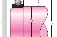
56 11.9 Selection of Tapered Roller Bearings Tapered roller bearings have a number of features that make them complicated The tapered roller bearing assembly consist of four components as shown in figure 11.3: Cone (inner ring) Cup (outer ring) Tapered rollers Cage (spacer retainer) 56
57 A tapered roller bearing carries both radial and thrust (axial) loads, or any combination of the two. If there is no external thrust load, there is still a thrust reaction within the bearing due to the taper shape of the bearing. To avoid the separation of the races and the rollers, the thrust load must be resisted by an equal and opposite force. This is can be done by use at least two tapered roller bearings on a shaft 57
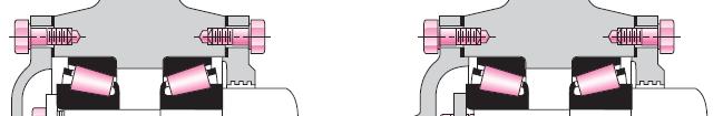
58 . In this case, the two bearings can be mounted either: The cone fronts facing each other (It is called indirect mounting) The cone backs facing each other (It is called direct mounting) 58

59 59
60 . The thrust component F a produced by a pure radial load F r is p a p y p r specified by the Timken Company as: F a = 0.47FF Where K is the ratio of the radial load rating of the bearing to the thrust load rating In design of bearing, the initial value of K is chosen to be K = 1.50 for radial bearing K = 0.75 for steep-angle bearings After the analysis is done, the correction value for K is reselected from the catalogue and the analysis is repeated. K r 60


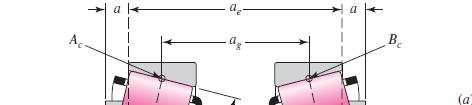
61 The figure shows a typical bearing mounting subjected to an external thrust load T e. The radial reactions F ra and F rb are computed by taking moments about the effective load centers G. The distance for the value of a which is shown in figure 11.3 is obtained from the catalog rating sheets. G G F ra T e F rb 61
62 62
63 63
64 The equivalent radial load on the bearings F 0.47FrB = 0.4F + K + Te Bearing A: ea ra A K B Bearing B: F eb 0.47FrA = 0.4F + rb K B Te K A After we calculate the value of F ea and F eb, we check the following: IF F ra > F ea use F ra for design of baring A. IF F ra < F ea use F ea for design of baring A. IF F rb > F eb use F rb for design of baring B. IF F rb < F eb use F eb for design of baring B. 64
65 Steps in Tapered Roller Bearing Selection Given required bearing life L 10 and load arranegment Determine applied radial F ex and thrust T ex loads Distribute radial loads to bearings: F ra and F rb using estimated a value to locate load center Estimate Bearing K factors for induced thrust Calculate l equivalent radial lloads F ea and F eb using estimated t dk factor Calculate rated load using actual load and desired life Select bearing from those available (in table) Check bearing loads using actual K factor and a values
66 Example The gear-reduction unit is arranged to rotate the cup while the cone is stationary. Bearing A takes the thrust load of 250 lb and, in addition, has a radial load 875 lb. Bearing B is subjected to a pure radial load of 625 lb. The speed is 150 rev/min. The desired L 10 life is 90 kh. The desired shaft diameters are in at A and 1 in at B. Select suitable tapered roller bearings, using an application factor of unity. 66
67 Solution Given: At Bearing A: T e =250 lb, F ra =875 lb, d A = in. At Bearing B: F rb =625 lb, d B =1 in. L 10 = 90 kh, n D=150 rev/min. R=.9 Assume an initial value for K A and K B as 1.5 F ea = 0.4F ra + K A 0.47FF rb + Te K B 0.47(625) = 0.4(875) = 1020lb
68 Since F ea > F ra use F ea for design of bearing A. Form equation 11-3 C ( 9000)( 150)( 60) ( 3000 )( 500 )( 60 ) 1/ a 3 /10 10 = = LDnD 60 FD = lb L R n R Now, go figure and with (d A =1.125 in ) select form columns 4 and 5 the value of C 10 that is equal or near to the value that we calculate in equation above Thus, we select cone, a cup, and K A=1.69 Calculate F ea and then C 10 again with the corrected value of K A, we get: C 10 =2130 lb. 68


69 69
70 Again go tofigure and with (d A =1.125 in ) select form column 4 the value of C 10 that is equal or near to the value that we calculate in equation above we have the same values: cone, a cup, and K A =
71 For bearing B: F F ra eb.4frb K B Te K = + A 0.47(875) = 0.4(625) = 240lb 1.69 Since F rb > F eb use F rb for design of bearing B Form equation 11-3 C ( 9000)( 150)( 60) ( 3000)( 500)( 60) 1/ a 3 /10 10 = = LDnD 60 FD = lb LRnR 60 71
72 Now,,go to figure and with (d B =1 in) there are five bearings from which to choose. The one at the top of the list has the smallest rating, the smallest OD, and the narrowest width. Thus, we select Cone, a Cup, C 10 =1570 lb and K B=1.45 Calculate F eb and then C 10 again with the corrected value of K B, we get the same C 10 =1210 lb. So the selection for bearing Bis:07100 Cone, a Cup, C 10 =1570 lb and K B =


73 Problem A gear-reduction unit uses the countershaft depicted in the figure. Find the two bearing reactions. The bearings are to be angular-contact ball bearings, having a desired life of 40 kh when used at 200 rev/min. Use 1.2 for the application factor and a reliability goal for the bearing pair of Select the bearings from Tbl Table
74 Solution The bearings are to be angular-contact ball bearings, having a desired life of : L D = 40 kh n D = 200 rev/min. Application factor f = 1.2 Reliability goal R 2 = 0.95 Select the bearings from Table
75 To find the reliability for each bearing: R 2 = (R) 2 R=( R 2 ) 1/2 ==(0.95) 1/2 = The torque at gear A: T = 240(12)(cos 20 ) = 2706 lbf in The force at gear B can be found by: 2706 F = = o 6cos lbf 75
76 In xy-plane: p M R R O y C y O y = -82.1(16) - 210(30) + 42R = 0 = 181 lbf = = 111 lbf C 76
77 In xz-plane: z MO = 226(16) - 452(30) - 42Rc = 0 R R R z C z O O = -237 lbf = = 12 lbf = + = 2 2 1/2 ( ) 112 lbf Ans /2 RC = ( ) = 298 lbf Ans. FeO = 1.2(112) = lbf FeC = 1.2(298) = lbf (200)(60) xd = = (C 1 0) O = [ln(1/ 0.975)] 1/ = 1438 lbf or kn 480 ( C10) C = [ln(1/ 0.975)] 1/ = 3825 lbf or kn 1/3 1/3 77
78 Bearing at O: Choose a deep-groove mm with C 10 = 6.89 kn and C 0 = 3.10 kn. Bearing at C: Choose a deep-groove mm with C 10 = 19.5 kn and C 0 = 10.0 kn. Note: It may be an advantage antage to use identical mm bearings in a gearreduction unit. 78


79 79
80 80
81 81
82 Problem The worm shaft shown in part a of the figure transmits 1.35 hp at 600 rev/min. A static force analysis gave the results shown in part b of the figure. Bearing A is to be an angular-contact ball bearing mounted to take the 555-lbf thrust load. The bearing at B is to take only the radial load, so a straight roller bearing will be employed. Use an application factor of 1.3, a desired life of 25 kh, and a reliability goal, combined, of Specify each bearing. 82
83 Figure P11-14: (a) Worm and worm gear; (b) force analysis of worm shaft, forces in pounds. 83
84 Solution The worm shaft transmits 1.35 hp at 600 rev/min. Bearing A is to be an angular-contact ball bearing mounted to take the 555-lbf thrust load. Bearing B takes only radial load, so a straight roller bearing will be employed. Application factor f = 1.3 n D =25 kh, R=
85 Bearing at A (Ball) F r = ( ) 1/2 = 215 lbf = kn F a = 555 lbf = 2.47 kn Trial #1: Since we do not have a value for the specification of the bearing, we start t by selecting one of the bearing from the table. Therefore, select a mm angular-contact with C 10 = 90.4 kn and C 0 = 63.0 kn. 85
86 F a / C 0 = 2.47 / 63.0 = a 0 Form table 11-1: by interpolation e = F a / VF r = 2.47/ [(1)0.957]=2.581 > e From equation (11-9) i = 2 F e =X 2 VF r +Y 2 F a X 2 =0.56, and Y 2 =1.88 by interpolation F e = (0.56)(1)(0.957)+1.88(2.47)=5.18 kn 86
87 With the application factor F D =1.3(5.18)=6.73kN C L 10 D = FD L nd / LRnR = L 1/ 3 ( LDnD / L n ) R R 1/ [ ln( 1/ R) ] ( )( 600 ) (60) rev 10 = 6 ( 10 )rev 900 C [ ln( 1/ 0.99) ] 7kN 10 = = 1/ = 1/ 3 We found that: (C 10 ) calculated > (C 10 ) selected from the table kn > 90.4kN, Therefore, we try another bearing with the specification: Select a mm angular-contact with C 10 = 121 kn and C 0 = 85.0 kn. 87
88 Trial #2: Tentatively select a mm angular-contact ball with C 10 = 121 kn and C 0 = 85 kn. F a / C 0 = 2.47 / 85.0 = Form table 11-1: by interpolation e = F a / VF r = 2.47/ [(1)0.957]=2.581 > e From equation (11-9) i = 2 F e =X 2 VF r +Y 2 F a X 2 =0.56, and Y 2 =1.98 by interpolation F e = (0.56)(1)(0.957) (2.47) = kn With the application factor F D =1.3(5.427) = 7.05kN 88
89 C L 10 D n = D F D / L 1/ 3 ( L ) DnD / L n R R 1/ [ ln( 1/ R) ] L ( )( 600 ) (60) rev R n R = L 10 = ( 6 10 ) rev = C [ ln( 1/ 0.99) ] 82kN 10 = = 1/ / 3 We found that: (C 10 ) calculated < (C 10 ) selected from the table kn < 121kN Therefore the specification of the bearing A is: A 02 series angular-contact with Bore 95 mm, C 10 = 121 kn, and C 0 = 85.0 kn. 0 89
90 Bearing at B (Roller): F r = ( ) 1/2 = lbf = kn F D =1.3(F r ) = 0.44 kn ( LDnD / LRnR ) 4.439[ ln( 1/ R) ] ( 25000)( 600) 1/ 3 C10 = FD 1/ L (60) rev LDnD / LRnR = = = 900 L ( 6 10 )rev 10 3 /10 C [ ln( 1/ 0.99) ] 34kN 10 = = 1/ From table 11-3, using a 02 series cylindrical roller bearing with Bore 25 mm, C 10 = 16.8 kn, and C 0 = 8.8 kn. 90
91 91
92 92
93 93
94 94
95 95


96 Mounting and Enclosure 96
97 97


98 98
99 99
100 100
101 PREPARATION FOR MOUNTING AND DISMOUNTING. Before mounting, all the necessary parts, tool, equipment and data need to be at hand. It is also recommended that any drawings or instruction be studied to determine the correct order in which to assemble the various components. Housing, shafts, seals and other components of the bearing arrangement need to be checked to see that they are clean, particularly any threaded holes, leads or grooves where remnants of previous machining operation might have collected. 101
102 MOUNTING METHOD Depending on the bearing type, and size, mechanical, thermal and hydraulic methods are used for mounting. 1. Cold Mounting Method. 2. Hot Mounting Method 102


103 COLD MOUNTING If the fit is not too tight, small bearings may be driven into position by applying light hammer blows to a sleeve placed against the bearing ring face. The blows should be evenly distributed around the ring to prevent the bearing from tilting or skewing. The use of the mounting dolly instead of a sleeve allows the mounting force to be applied centrally. 103


104 HOT MOUNTING It is generally not possible to mount larger bearing in the cold state, as the force required to mount a bearing increases very considerably with increasing bearing size. The inner rings or the housings are there fore heated prior to mounting. Bearing should not be heated to more than 125c as otherwise dimensional changes caused dby alterations in the structure of the bearing material may occur. Bearing fitted with shields or seals should not be heated above 80c because of their grease fill or seal material. 104
105 DISMOUNTING METHOD If the bearings are to be used again after removal, the force used to dismount them must never be applied through the rolling elements. With separable bearings, the ring with the rolling element and cage assembly can be removed independently of the other ring. To dismount a bearing having an interference fit, the tools described in the following section may be used, the choice of tools will depend on bearing type, size and fit. 1. Cold dismounting. 2. Hot dismounting. 105
106 HOT DISMOUNTING Special induction heaters have been developed to dismount the inner ring of cylindrical roller bearing having no flanges or only one flange. They heat the inner ring rapidly without heating the shaft to any degree, so that the expanded ring can easily be removed. 106
107 BEARING LUBRICATION Lubrication reduces friction. It also prevents wear and corrosion, and guards against solid and liquid contamination. Theoretically, a properly p lubricated bearing operating under ideal conditions will last forever. This is not possible in reality, of course. But a properly lubricated bearing has the best chance of achieving its maximum service life. 107

108 LUBRICANT SUPLLY SYSTEM Oil and grease require different types of supply systems. Several oil and grease supply systems exist that meet the needs of various bearing applications. Oil supply systems include: oil baths, circulating oil systems, spray or mist systems, and the wick feed method. Grease supply systems include: housings (with or without grease fittings), grease chamber lubrication, and the grease quantity regulator. 108


109 LUBRICANT SUPLLY SYSTEM 109
T=10(180cos40)= lbf.in T1+T2=0 F=1378.9/5cos25= lbf. Ryc=131.4 Ryc-180sin40-Fsin25+Roy= Roy=112.86
= lbf.in T1+T2=0 F=1378.9/5cos25= lbf. Ryc=131.4 Ryc-180sin40-Fsin25+Roy= Roy=112.86") Q2(13p).A gear-reduction unit uses the countershaft depicted in the figure. Find the two bearing reactions.the bearings are to be angular-contact ball bearings, having a desired life of 50 kh when used
Q2(13p).A gear-reduction unit uses the countershaft depicted in the figure. Find the two bearing reactions.the bearings are to be angular-contact ball bearings, having a desired life of 50 kh when used
Tribology Prof. Dr. Harish Hirani Department of Mechanical Engineering Indian Institute of Technology, Delhi
 Tribology Prof. Dr. Harish Hirani Department of Mechanical Engineering Indian Institute of Technology, Delhi Lecture No. # 29 Rolling Element Bearings (Contd.) Welcome to 29 th lecture of video course
Chapter (300)(60) 10 6 = 540 Ans. F D = 1.2(1.898) = kn. 540 C 10 = [ln(1/0.9)] 1/1.483 = kn Ans.
![Chapter (300)(60) 10 6 = 540 Ans. F D = 1.2(1.898) = kn. 540 C 10 = [ln(1/0.9)] 1/1.483 = kn Ans.](/thumbs/72/66661885.jpg "Chapter (300)(60) 10 6 = 540 Ans. F D = 1.2(1.898) = kn. 540 C 10 = [ln(1/0.9)] 1/1.483 = kn Ans.") Chapter - For the deep-groove 02-series ball bearing with R = 0.90, the design life x D, in multiples of rating life, is The design radial load F D is From Eq. (-6), x D = 30 000(300)(60) 0 6 = 540 F D
Chapter - For the deep-groove 02-series ball bearing with R = 0.90, the design life x D, in multiples of rating life, is The design radial load F D is From Eq. (-6), x D = 30 000(300)(60) 0 6 = 540 F D
ENGINEERING INFORMATION TABLE OF CONTENTS SHAFT AND HOUSING FITS LUBRICATION LIFE AND LOAD RATINGS RADIAL CLEARANCE CHART
 ENGINEERING INFORMATION TABLE OF CONTENTS ENGINEERING INFORMATION SHAFT AND HOUSING FITS LUBRICATION LIFE AND LOAD RATINGS RADIAL CLEARANCE CHART SHAFT AND HOUSING FITS FOR METRIC RADIAL BALL AND ROLLER
BEARINGS Pillow Blocks
 The bearing size is usually selected according to the required bearing life and reliability under a specified type of load charged on the bearing. The load applied to the bearing operating under a static
S.C. Rulmenti S.A. Barlad Romania Republicii Street No
 SELECTION OF BEARING SIZE Basic load ratings The size of a bearing is selected considering the load in the used rolling bearing and also depends on the operational rating life and prescribed operating
XR Series. Introduction. Design Features. Availability. Applications
 Kaydon Bearings Slewing Ring Bearings Catalog 390 Introduction The consists of Kaydon cross roller bearings. They provide a high degree of stiffness and low rotational torque within a minimal envelope.
ENT345 Mechanical Components Design
 1) LOAD AND STRESS ANALYSIS i. Principle stress ii. The maximum shear stress iii. The endurance strength of shaft. 1) Problem 3-71 A countershaft carrying two-v belt pulleys is shown in the figure. Pulley
The SKF model for calculating the frictional moment
 The SKF model for calculating the frictional moment The SKF model for calculating the frictional moment Bearing friction is not constant and depends on certain tribological phenomena that occur in the
The basic dynamic load rating C is a statistical number and it is based on 90% of the bearings surviving 50 km of travel carrying the full load.
 Technical data Load Rating & Life Under normal conditions, the linear rail system can be damaged by metal fatigue as the result of repeated stress. The repeated stress causes flaking of the raceways and
ISO INTERNATIONAL STANDARD. Rolling bearings Thermal speed rating Calculation and coefficients
 INTERNATIONAL STANDARD ISO 1512 First edition 200-12-01 Rolling bearings Thermal speed rating Calculation and coefficients Roulements Vitesse de référence thermique Calculs et facteurs de correction Reference
Friction in Anti-friction Bearings
 Tribology Prof. Dr. Harish Hirani Department of Mechanical Engineering Indian Institute of Technology, Delhi Lecture No. # 32 Friction of Rolling Element Bearing Welcome to thirty second lecture of video
Sliding Bearings. Fig.(1) (a) Full-journal bearing and (b) partial-journal bearing
 (a) Full-journal bearing and (b) partial-journal bearing") Sliding Bearings The goal of a bearing is to provide relative positioning and rotational freedom while transmitting a load between two parts, commonly a shaft and its housing. The object of lubrication
Sliding Bearings The goal of a bearing is to provide relative positioning and rotational freedom while transmitting a load between two parts, commonly a shaft and its housing. The object of lubrication
Precision Ball Screw/Spline
 58-2E Models BNS-A, BNS, NS-A and NS Seal Outer ring Shim plate Seal Spline nut Seal Collar Shim plate Seal End cap Ball Outer ring Ball screw nut Outer ring Ball Retainer Retainer Outer ring Point of
Identification Number
 Identification Number The specification of Micro Linear Way LWL is specified by the identification number, which consists of a model code, a size, a part code, a preload symbol, a classification symbol,
Not all thin-section bearings are created equal. KAYDON new capacity calculations. Robert Roos, Scott Hansen
 Not all thin-section bearings are created equal KAYDON new capacity calculations Robert Roos, Scott Hansen A white paper from KAYDON Bearings Division Table of Contents Abstract... pg. Introduction...
FOUR-POINT CONTACT SLEWING RINGS - without gear [ O ]
![FOUR-POINT CONTACT SLEWING RINGS - without gear [ O ]](/thumbs/96/126795264.jpg "FOUR-POINT CONTACT SLEWING RINGS - without gear [ O ]") FOUR-POINT CONTACT SLEWING RINGS - without gear [ O ] Number of the Loading Boundary Dimensions Static Ax.Basic Load Rating Designation Weight Abutment Dimensions Curve d D T C oa G J 1 J 2 N 1 N 2 n 1
FOUR-POINT CONTACT SLEWING RINGS - without gear [ O ] Number of the Loading Boundary Dimensions Static Ax.Basic Load Rating Designation Weight Abutment Dimensions Curve d D T C oa G J 1 J 2 N 1 N 2 n 1
Bearing Internal Clearance and Preload
 . Bearing Internal Clearance and Preload. Bearing internal clearance Bearing internal clearance is the amount of internal free movement before mounting. As shown in Fig.., when either the inner ring or
Bearing Standards page TAG KW B25 CLT JL JLM L LM SDA0 SDA9 UB2 UC2 UCF2 UCFC2 UCFL2 UCP2
 Bearing Standards page 0 Deep Groove Ball Bearing 8 8TAG OneWay Thrust Ball Bearing for Automobile KingPins 0 0 0 Tapered Roller Bearing 80 0 Tapered Roller Bearing 80 0 Tapered Roller Bearing 80 8KW Inch
SNL plummer block housings, 2, 3, 5 and 6 series Other bearing housings Large SNL plummer block housings
 Bearing housings SNL plummer block housings, 2, 3, 5 and 6 series... 1033 Other bearing housings... 1058 Large SNL plummer block housings... 1058 SONL plummer block housings... 1059 SDG plummer block housings...
11/27/ :00 PM. Chapter 12. Lubrication and Journal Bearings. Dr. Mohammad Suliman Abuhaiba, PE
 Chapter 12 Lubrication and Journal Bearings 1 2 Chapter Outline 1. Types of Lubrication 2. Viscosity 3. Petroff s Equation 4. Stable Lubrication 5. Thick-Film Lubrication 6. Hydrodynamic Theory 7. Design
PROCESS FOR SELECTING NB LINEAR SYSTEM
 The NB linear system is a linear motion mechanism which utilizes the recirculating movement of ball or roller elements to provide smooth and accurate linear travel. NB offers a wide range of linear motion
Dimensions of propulsion shafts and their permissible torsional vibration stresses
 (Feb 2005) (orr.1 Mar 2012) (orr.2 Nov 2012) Dimensions of propulsion shafts and their permissible torsional vibration stresses.1 Scope This UR applies to propulsion shafts such as intermediate and propeller
second PLSA line R310EN 3308 ( )
") 01_1 Planetary st Headline_36 Screw Assemblies pt/14.4 mm second PLSA line R310EN 3308 (2011-09) 2 Planetary Screw Assemblies PLSA Planetary Screw Assemblies PLSA Product Overview 3 Nuts, Screws, Screw
01_1 Planetary st Headline_36 Screw Assemblies pt/14.4 mm second PLSA line R310EN 3308 (2011-09) 2 Planetary Screw Assemblies PLSA Planetary Screw Assemblies PLSA Product Overview 3 Nuts, Screws, Screw
Not all thin-section bearings are created equal. KAYDON new capacity calculations. Robert Roos, Scott Hansen
 Not all thin-section bearings are created equal KAYDON new capacity calculations Robert Roos, Scott Hansen A white paper from KAYDON Corporation Bearings Division Table of Contents Abstract... pg. Introduction...
MEMS Project 2 Assignment. Design of a Shaft to Transmit Torque Between Two Pulleys
 MEMS 029 Project 2 Assignment Design of a Shaft to Transmit Torque Between Two Pulleys Date: February 5, 206 Instructor: Dr. Stephen Ludwick Product Definition Shafts are incredibly important in order
Rolling Bearings Ball Bearing Roller Bearing Special Bearing Rolling Bearings
 Rolling Bearings Bearing Standards page 0 Deep Groove Ball Bearing 8 8TAG OneWay Thrust Ball Bearing for Automobile KingPins 0 0 0 Tapered Roller Bearing 80 0 Tapered Roller Bearing 80 0 Tapered Roller
Classic Mini ( ) Transmission Bearing Load Estimates During Service
 Transmission Bearing Load Estimates During Service") Classic Mini (1959 2000) Transmission Bearing Load Estimates During Service Purpose The removal and replacement of the nuts at the ends of the first and third motion shafts in the classic Mini transmission
Classic Mini (1959 2000) Transmission Bearing Load Estimates During Service Purpose The removal and replacement of the nuts at the ends of the first and third motion shafts in the classic Mini transmission
( ) 5. Bearing internal load distribution and displacement. 5.1 Bearing internal load distribution
 5. Bearing internal load distribution and displacement. 5.1 Bearing internal load distribution") 5. internal load distribution and displacement 5. internal load distribution This section will begin by examing the effect of a radial load F r and an axial load F a applied on a single-row bearing with
5. internal load distribution and displacement 5. internal load distribution This section will begin by examing the effect of a radial load F r and an axial load F a applied on a single-row bearing with
SOLUTION (17.3) Known: A simply supported steel shaft is connected to an electric motor with a flexible coupling.
 Known: A simply supported steel shaft is connected to an electric motor with a flexible coupling.") SOLUTION (17.3) Known: A simply supported steel shaft is connected to an electric motor with a flexible coupling. Find: Determine the value of the critical speed of rotation for the shaft. Schematic and
SOLUTION (17.3) Known: A simply supported steel shaft is connected to an electric motor with a flexible coupling. Find: Determine the value of the critical speed of rotation for the shaft. Schematic and
BNA Series. PLENUM FAN with Backward Wheels
 BNA Series PLENUM FAN with Backward Wheels BNA Series BNA Series Plenum Fans Backward wheels Kruger Plenum Fans are designed for air handling applications where the fan operates unhoused within a plenum.
Mechanical Design. Design of Shaft
 Mechanical Design Design of Shaft Outline Practical information Shaft design Definition of shaft? It is a rotating member, in general, has a circular cross-section and is used to transmit power. The shaft
HEAVY DUTY SWING-OUT VALVE
 ISO 900 REGISTERED COMPANY Akron Brass Company. 20 All rights reserved. No portion of this can be reproduced without the express written consent of Akron Brass Company. We will not be responsible for:
THE LOSMANDY G-11 MOUNT
 Checking the parts THE LOSMANDY G-11 MOUNT Depending on which accessories you ordered, your G-11 mount was shipped in four or more boxes. The contents of each box are as follows: Equatorial Mount Adjustable
ROLLER BEARING FAILURES IN REDUCTION GEAR CAUSED BY INADEQUATE DAMPING BY ELASTIC COUPLINGS FOR LOW ORDER EXCITATIONS
 ROLLER BEARIG FAILURES I REDUCTIO GEAR CAUSED BY IADEQUATE DAMPIG BY ELASTIC COUPLIGS FOR LOW ORDER EXCITATIOS ~by Herbert Roeser, Trans Marine Propulsion Systems, Inc. Seattle Flexible couplings provide
12/25/ :27 PM. Chapter 14. Spur and Helical Gears. Mohammad Suliman Abuhaiba, Ph.D., PE
 Chapter 14 Spur and Helical Gears 1 2 The Lewis Bending Equation Equation to estimate bending stress in gear teeth in which tooth form entered into the formulation: 3 The Lewis Bending Equation Assume
Accelerated Life Test of Mechanical Components Under Corrosive Condition
 Accelerated Life Test of Mechanical Components Under Corrosive Condition Cheng Zhang, and Steven Y. Liang G. W. Woodruff School of Mechanical Engineering Georgia Institute of Technology Atlanta, GA 30332,
Dynamic Analysis for Needle Roller Bearings Under Planetary Motion
 NTN TECHNICAL REVIEW No.75 2007 Technical Paper Dynamic Analysis for Needle Roller Bearings Under Planetary Motion Tomoya SAKAGUCHI A dynamic analysis tool for needle roller bearings in planetary gear
HEAVY DUTY SWING-OUT VALVE
 ISO 900 REGISTERED COMPANY HEAVY DUTY SWING-OUT VALVE 52 53 23 5 2 2 3 28 39 NOT USED WITH SZ HANDLE 2 NOT USED WITH SZ HANDLE 5 2 3 7 9 9 Premier Farnell Corporation. 20 All rights reserved. No portion
The SynchMotion. Retainer
 106 G99TE13-0809 Linear Guideways QE Series 2-9 QE Type Quiet Linear Guideway, with SynchMotion TM Technology The development of HIIN-QE linear guideway is based on a four-row circular-arc contact. The
Linear guide drives. Synchronous shafts The use of synchronous shafts enables several linear axes to be operated with one drive.
 Linear guide drives Drive concept The linear guides are driven via the hollow shaft in the drive head. The drive head is used to directly install a motor or alternatively (in connection with a center shaft)
Load Washers. Force. for Forces of 7, kn. F z. Type 9001A A 9081B, 9091B
 Force Load Washers for Forces of 7,5... 1 200 kn Type 9001A... 9071A 9081B, 9091B 1-component force sensor for measuring dynamic and quasistatic forces in z direction. F z Calibrated measuring range 100
ZF Maschinenantriebe GmbH Industrial Drives. Planetary gearboxes Economy Series for Servomotors
 ZF Maschinenantriebe GmbH Industrial rives Planetary gearboxes Economy Series for Servomotors 2 ZF-uoplan 2K Two-speed Gearboxes ZF-Ecolift Elevator Gearboxes ZF-Servoplan G ompact Gearbox ZF-Tiratron
PumPac 8000, 8000-BB and 8000-AAB Series
 PumPac 8000, 8000-BB and 8000-AAB Series The PumPac 8000 Series consists of a matched set of 40 A) and 15 B) angular contact ball beargs with computer optimized ternal design. They are manufactured to
Mehul.K.Modh et al Int J Engg Techsci Vol 2(3) 2011,
 2011,") Mehul.K.Modh et al Int J Engg Techsci Vol () 011,-5 Design, Improvement and Thrust Bearing Analysis of Oil Expeller Machine Mehul.K.Modh 1*, J.R.Mevada 1 L.C. Institute of Technology, Bhandu,Mehasana,
Mehul.K.Modh et al Int J Engg Techsci Vol () 011,-5 Design, Improvement and Thrust Bearing Analysis of Oil Expeller Machine Mehul.K.Modh 1*, J.R.Mevada 1 L.C. Institute of Technology, Bhandu,Mehasana,
Sliding Contact Bearings
 Sliding Contact Bearings Classification of Bearings 1. According to the direction of load to be supported. The bearings under this group are classified as: (a) Radial bearings (b) Thrust bearings. In radial
CHAPTER 8 SCREWS, FASTENERS, NONPERMANENT JOINTS
 CHAPTER 8 SCREWS, FASTENERS, NONPERMANENT JOINTS This chapter deals with the design and analysis of nonpermanent fasteners such as bolts, power screws, cap screws, setscrews, eys and pins. 8- Standards
CYLINDRICAL ROLLER BEARINGS CARRYING THRUST LOAD
 CYLINDRICAL ROLLER BEARINGS CARRYING THRUST LOAD Gh. PRISACARU, Sp. CRETU, D. N. OLARU "Gh. Asachi Technical University, Department of Machine Design & Tribology, Bvd. D. Mangeron, 6-63, 66 Iasi, ROMANIA;
Planetary Screw Assemblies PLSA
 Planetary Screw Assemblies PLSA R310EN 3308 (2011-09) The Drive & Control Company C/ Centauro, 13 Área Empresarial Las Cubiertas 28971-Griñón (Madrid) T. 0034 91 126 6627 info@diversiatec.com www.diversiatec.com
UNIT 2 FRICTION 2.1 INTRODUCTION. Structure. 2.1 Introduction
 UNIT FICTION Structure.1 Introduction Objectives. Types of.3 Laws of Dry.4 Static and Kinetic.5 Coefficient of.6 Angle of epose.7 Least Force equired to Drag a Body on a ough Horizontal Plane.8 Horizontal
/2" Heavy Duty Swing-Out
 Premier Farnell Corporation. 0 All rights reserved. No portion of this can be reproduced without the express written consent of Premier Farnell Corporation. ISO 900 REGISTERED COMPANY We will not be responsible
W h y Co n s i d e r An y t h i n g El s e?
 Dodge Grip Tight Ball Bearings DODGE GRIP TIGHT Ad a p t e r... W i t h Al l It s Ad v a n t a g e s, W h y Co n s i d e r An y t h i n g El s e? DODGE proudly presents a totally different ball bearing
Overview. Dry Friction Wedges Flatbelts Screws Bearings Rolling Resistance
 Friction Chapter 8 Overview Dry Friction Wedges Flatbelts Screws Bearings Rolling Resistance Dry Friction Friction is defined as a force of resistance acting on a body which prevents slipping of the body
INFLUENCE OF THE LUBRICATION ON FRICTION IN MICROBALL BEARINGS
 INFLUENCE OF THE LUBRICATION ON FRICTION IN MICROBALL BEARINGS Mihaela Rodica Bălan, Liviu Balan,Vasile Ciprian Stamate, Alina-Corina Dumitraşcu, Dumitru Olaru Gheorghe Asachi Technical University of Iasi,
Conversion Kit for: 7620 and 7820 Swing-Out Valves ft-lbs ft-lbs 8835/ ft-lbs
 ISO 900 REGISTERED COMPANY HEAVY DUTY SWING-OUT VALVE 52 53 23 5 2 2 3 28 39 NOT USED WITH SZ HANDLE 2 NOT USED WITH SZ HANDLE 5 2 3 7 9 9 Premier Farnell Corporation. 20 All rights reserved. No portion
Design, Modelling and Analysis of a Single Raw Four Point Angular Contact Split Ball Bearing to Increase its Life.
 Design, Modelling and Analysis of a Single Raw Four Point Angular Contact Split Ball Bearing to Increase its Life. Pranav B. Bhatt #1, Prof. N. L. Mehta *2 #1 M. E. Mechanical (CAD/CAM) Student, Department
Planetary Screw Assemblies PLSA
 Planetary Screw Assemblies PLSA Ernst-Sachs-Straße 100 97424 Schweinfurt Tel. +49 9721 937-0 Fax +49 9721 937-275 www.boschrexroth.com Catalog "Planetary Screw Assemblies PLSA" R310XX 3308 (2014.01) Dear
PERFORMANCE EVALUATION OF OVERLOAD ABSORBING GEAR COUPLINGS
 International Journal of Mechanical Engineering and Technology (IJMET) Volume 9, Issue 12, December 2018, pp. 1240 1255, Article ID: IJMET_09_12_126 Available online at http://www.ia aeme.com/ijmet/issues.asp?jtype=ijmet&vtype=
+ + = integer (13-15) πm. z 2 z 2 θ 1. Fig Constrained Gear System Fig Constrained Gear System Containing a Rack
 πm. z 2 z 2 θ 1. Fig Constrained Gear System Fig Constrained Gear System Containing a Rack") Figure 13-8 shows a constrained gear system in which a rack is meshed. The heavy line in Figure 13-8 corresponds to the belt in Figure 13-7. If the length of the belt cannot be evenly divided by circular
Figure 13-8 shows a constrained gear system in which a rack is meshed. The heavy line in Figure 13-8 corresponds to the belt in Figure 13-7. If the length of the belt cannot be evenly divided by circular
Not All Thin-Section Bearings Are Created Equal:
 Not All Thin-Section Bearings Are Created Equal: KAYDON NEW CAPACITY CALCULATIONS (Courtesy Kaydon Corp. Bearings Division Robert Roos and Scott Hansen Management Summary American Bearing Manufacturers
5. STRESS CONCENTRATIONS. and strains in shafts apply only to solid and hollow circular shafts while they are in the
 5. STRESS CONCENTRATIONS So far in this thesis, most of the formulas we have seen to calculate the stresses and strains in shafts apply only to solid and hollow circular shafts while they are in the elastic
Tuesday, February 11, Chapter 3. Load and Stress Analysis. Dr. Mohammad Suliman Abuhaiba, PE
 1 Chapter 3 Load and Stress Analysis 2 Chapter Outline Equilibrium & Free-Body Diagrams Shear Force and Bending Moments in Beams Singularity Functions Stress Cartesian Stress Components Mohr s Circle for
Flexible Mechanical Elements
 lexible Mechanical Elements INTRODUCTION Belts, ropes, chains, and other similar elastic or flexible machine elements are used in conveying systems and in the transmission of power over comparatively long
R-Plus System Frontespizio_R_PlusSystem.indd 1 11/06/ :32:02
 R-Plus System R-Plus System R-Plus system R-Plus system description Fig. R-Plus system R-Plus System is Rollon s series of rack & pinion driven actuators. Rollon R-Plus System series linear units are designed
Ball screw. Linear. Coupling cover. 1Positioning table of a structure with enhanced sealing property. 3 High corrosion resistance
 Cleanroom Precision Positioning Table TC Ball screw TC EB Slide table inear Way Side cover Stainless sheet Motor bracket inear Coupling cover Pipe threads for suction connector Points ight weight, low
GB/T Translated English of Chinese Standard: GB/T NATIONAL STANDARD OF THE
 Translated English of Chinese Standard: GB/T24607-2009 www.chinesestandard.net Sales@ChineseStandard.net GB NATIONAL STANDARD OF THE PEOPLE S REPUBLIC OF CHINA ICS 21.100.20 J 11 GB/T 24607-2009 Rolling
Modeling Method Analysis of the Friction Torque for High Speed Spindle Bearing
 MATEC Web of Conferences 75, 0308 (08) https://doi.org/0.05/matecconf/08750308 IFCAE-IOT 08 Modeling Method Analysis of the Friction Torque for High Speed Spindle Bearing Songsheng Li,, HuihangChen,, Haibing
Improvement in the Design & Manufacturing of Twin Worm Self Locking Technique and applications
 Improvement in the Design & Manufacturing of Twin Worm Self Locking Technique and applications Prof. P.B. Kadam 1, Prof. M.R. Todkar 2 1 Assistant Professor, Mechanical Engineering Department, T.K.I.E.T.Warananagar,
ER2 Short-head Electric Chain Hoist
 O/M NO.SHER2-0903-CE-00 ER2 Short-head Electric Chain Hoist (250kg to 5t) Operation Manual (SHER2M/SHER2SG/SHER2SP) Introduction The KITO Short-head Electric Chain Hoist is intended for effective use in
New Representation of Bearings in LS-DYNA
 13 th International LS-DYNA Users Conference Session: Aerospace New Representation of Bearings in LS-DYNA Kelly S. Carney Samuel A. Howard NASA Glenn Research Center, Cleveland, OH 44135 Brad A. Miller
Points. Precision Positioning Table TU. Variation. Major product specifications With flange
 9 0 Precision Positioning Table Ball screw inear Points lide table with high accuracy and high rigidity in a single structure lide table Compact and slim type positioning table with an original U-shaped
ANGULAR CONTACT BEARINGS
 ANGULAR CONTACT S ANGULAR CONTACT S Angular Contact Bearing Design Angular contact bearings have one ring shouler remove, this may be from the inner or outer ring. This allows a larger ball complement
Comparison of Models for Rolling Bearing Dynamic Capacity and Life
 2013 STLE Annual Meeting & Exhibition May 5-9, 2013 Detroit Marriott at the Renaissance Center Detroit, Michigan, USA Comparison of Models for Rolling Bearing Dynamic Capacity and Life Rolling-Element
A nonlinear dynamic vibration model of defective bearings: The importance of modelling the finite size of rolling elements
 A nonlinear dynamic vibration model of defective bearings: The importance of modelling the finite size of rolling elements Alireza Moazenahmadi, Dick Petersen and Carl Howard School of Mechanical Engineering,
Dry System (Twin and DR Type Bearings) Lubricated System (Twin Type Bearings) Lubricated System (DR Type Bearings)
 Lubricated System (Twin Type Bearings) Lubricated System (DR Type Bearings)") This data sheet interacts with PRT2 Catalogue 54-56 Hepcootion No. 3 Load Life Information The load capacity and life expectancy of Hepcootion ring slides, segments and track systems is determined by many
This data sheet interacts with PRT2 Catalogue 54-56 Hepcootion No. 3 Load Life Information The load capacity and life expectancy of Hepcootion ring slides, segments and track systems is determined by many
LECTURE NOTES ENT345 MECHANICAL COMPONENTS DESIGN Lecture 6, 7 29/10/2015 SPUR AND HELICAL GEARS
 LECTURE NOTES ENT345 MECHANICAL COMPONENTS DESIGN Lecture 6, 7 29/10/2015 SPUR AND HELICAL GEARS Dr. HAFTIRMAN MECHANICAL ENGINEEERING PROGRAM SCHOOL OF MECHATRONIC ENGINEERING UniMAP COPYRIGHT RESERVED
C-Lube Linear Way ML Linear Way L ML LWL
 -Lube Linear ay ML Linear ay L MLLL -Lube Maintenance ree Series -Lube Linear ay ML ML long term maintenance free supported! The aquamarine end plate is the symbol of maintenance free. Identification umber
AE / AER Series. AER Series
 AE / AER Series Characteristic Highlights True helical gear design Precision helical gearing increases tooth to tooth contact ratio by over % vs spur gearing. The helix angle produces smooth and quiet
Journal bearing performance and metrology issues
 of Achievements in Materials and Manufacturing Engineering VOLUME 3 ISSUE 1 January 009 Journal bearing performance and metrology issues S. Sharma a, *, D. Hargreaves b, W. Scott b a School of Engineering
International Journal of Advance Engineering and Research Development
 Scientific Journal of Impact Factor(SJIF): 3.134 e-issn(o): 2348-4470 p-issn(p): 2348-6406 International Journal of Advance Engineering and Research Development Volume 2,Issue 5, May -2015 A REVIEW OF
 Identification The of -Lube Linear Roller Way Super MX is identified by the identification, which consists of model code, size, part code, material symbol preload symbol, classification symbol, interchangeable
Key words: Polymeric Composite Bearing, Clearance, FEM
 A study on the effect of the clearance on the contact stresses and kinematics of polymeric composite journal bearings under reciprocating sliding conditions Abstract The effect of the clearance on the
Automatic Level Maintenance Manual SAL-XX W/ AIR DAMPENED COMPENSATOR
 Automatic Level Maintenance Manual SAL-XX W/ AIR DAMPENED COMPENSATOR CST/Berger 2001 SAL 20/24/28/32 PAGE 1 REV. C 071803 Automatic Level Maintenance Manual User Calibration and Testing... 3 Circular
Replacement of Grid Coupling with Bush Pin Coupling in Blower
 Replacement of Grid Coupling with Bush Pin Coupling in Blower Ramees Rahman A 1, Dr S Sankar 2 Dr K S Senthil Kumar 3 P.G. Student, Department of Mechanical Engineering, NCERC, Thrissure, Kerala, India
EMA 3702 Mechanics & Materials Science (Mechanics of Materials) Chapter 3 Torsion
 Chapter 3 Torsion") EMA 3702 Mechanics & Materials Science (Mechanics of Materials) Chapter 3 Torsion Introduction Stress and strain in components subjected to torque T Circular Cross-section shape Material Shaft design Non-circular
EMA 3702 Mechanics & Materials Science (Mechanics of Materials) Chapter 3 Torsion Introduction Stress and strain in components subjected to torque T Circular Cross-section shape Material Shaft design Non-circular
Product description. Compact Modules. Characteristic features. Further highlights
 4 Compact Modules Product description Characteristic features Five fine-tuned sizes based on a compact precision aluminum profile with two integrated pre-tensioned ball rail systems Identical external
Design against fluctuating load
 Design against fluctuating load In many applications, the force acting on the spring is not constants but varies in magnitude with time. The valve springs of automotive engine subjected to millions of
Lecture Slides. Chapter 14. Spur and Helical Gears
 Lecture Slides Chapter 14 Spur and Helical Gears The McGraw-Hill Companies 2012 Chapter Outline Cantilever Beam Model of Bending Stress in Gear Tooth Fig. 14 1 Lewis Equation Lewis Equation Lewis Form
STATICS. Friction VECTOR MECHANICS FOR ENGINEERS: Eighth Edition CHAPTER. Ferdinand P. Beer E. Russell Johnston, Jr.
 Eighth E 8 Friction CHAPTER VECTOR MECHANICS FOR ENGINEERS: STATICS Ferdinand P. Beer E. Russell Johnston, Jr. Lecture Notes: J. Walt Oler Texas Tech University Contents Introduction Laws of Dry Friction.
Series 7500 Formed Metal Bellows Catalog 974C
 Series 00 Formed Metal Bellows Catalog C Innovators of the industry Bellows assemblies for safety valves, control valves, and regulators. When you look for a formed bellows which is reliable, has a long
Theory & Practice of Rotor Dynamics Prof. Rajiv Tiwari Department of Mechanical Engineering Indian Institute of Technology Guwahati
 Theory & Practice of Rotor Dynamics Prof. Rajiv Tiwari Department of Mechanical Engineering Indian Institute of Technology Guwahati Module - 8 Balancing Lecture - 1 Introduce To Rigid Rotor Balancing Till
CLUTCHES AND BRAKES. Square-jaw clutch
 Clutches: CLUTCHES AND BRAKES A Clutch is a mechanical device which is used to connect or disconnect the source of power from the remaining parts so the power transmission system at the will of the operator.
HRN/HRN-C Series Hydraulic Vane Rotary Actuators
 HRN/ Hydraulic Vane Rotary Actuators Vane Actuators Tork-Mor HRN Contents Features... 2 Ordering Information... Engineering Data / Specifications... Dimensions... Features... 1 Ordering Information...12
UNI EN ISO 9001:2008 UNI EN ISO 14001:2004 BS OHSAS 18001:2007 EC DIRECTIVE 2014/34/EU (ATEX) CERTIFIED MANAGEMENT SYSTEM
 CERTIFIED MANAGEMENT SYSTEM") EN ISM-BSM CERTIFIED Technology Made in Italy Since 1955 the Varvel Group has been making speed reducers and variators for light industry applications. Reliable partner in power transmission equipment
EN ISM-BSM CERTIFIED Technology Made in Italy Since 1955 the Varvel Group has been making speed reducers and variators for light industry applications. Reliable partner in power transmission equipment
CONNECTION DESIGN. Connections must be designed at the strength limit state
 CONNECTION DESIGN Connections must be designed at the strength limit state Average of the factored force effect at the connection and the force effect in the member at the same point At least 75% of the
CHAPTER 7 FINITE ELEMENT ANALYSIS OF DEEP GROOVE BALL BEARING
 113 CHAPTER 7 FINITE ELEMENT ANALYSIS OF DEEP GROOVE BALL BEARING 7. 1 INTRODUCTION Finite element computational methodology for rolling contact analysis of the bearing was proposed and it has several
Research Article Dynamic Carrying Capacity Analysis of Double-Row Four-Point Contact Ball Slewing Bearing
 Mathematical Problems in Engineering Volume 215, Article ID 8598, 7 pages http://dx.doi.org/1.1155/215/8598 Research Article Dynamic Carrying Capacity Analysis of Double-Row Four-Point Contact Ball Slewing
Lexium integrated drives
 Presentation GBX planetary gearbox Presentation In many cases the axis controller requires the use of a planetary gearbox for adjustment of speed of rotation and torque; the accuracy required by the application
Glossary Innovative Measurement Solutions
 Glossary GLOSSARY OF TERMS FOR TRANSDUCERS, LOAD CELLS AND WEIGH MODULES This purpose of this document is to provide a comprehensive, alphabetical list of terms and definitions commonly employed in the
Miniature Slide Guide Series with Retained Ball now Offers Complete Selection
 Miniature Slide Guide Series with Retained Ball now Offers Complete Selection Wide type of Miniature Slide Guide, providing greater allowable moment, is now available with retained ball structure. Due