Key words: Polymeric Composite Bearing, Clearance, FEM
|
|
|
- Jennifer Black
- 5 years ago
- Views:
Transcription
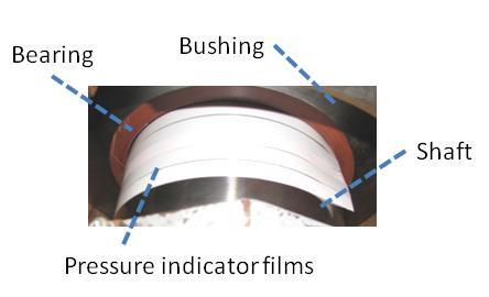
1 A study on the effect of the clearance on the contact stresses and kinematics of polymeric composite journal bearings under reciprocating sliding conditions Abstract The effect of the clearance on the contact stresses and kinematics of a polymeric composite journal bearing is investigated. To this purpose a test rig is devised, which is capable to measure the tribological characteristics of the large-scale composite bearings. Kinematics of the setup is simulated by a 2D FE model. Moreover, to evaluate the contact area between the bearing and shaft, pressure indicator films are used and a simplified 3D model is provided. Simulation results correspond closely to the experiments and it is shown that the clearance variation can have a big impact on the contact stresses distribution. Key words: Polymeric Composite Bearing, Clearance, FEM 1. Introduction The area of tribology deals with the design, friction, wear, and lubrication of interacting surfaces in relative motion. In recent years polymeric composite materials have been used increasingly for such tribological applications. Yet, by now, much of the knowledge on their tribological behavior is often empirical, and very limited predictive capability currently exists [1]. In this article, effects of the clearance between a composite bearing and shaft on the contact stresses and kinematics of a polymeric composite journal bearing are numerically investigated. Contact problems are very sensitive to minor profile changes in the contact bodies [2]. In addition, dimensional control methods for composites are mainly based on trial and error approaches [3], and tolerance control is not as good as in metal production. Hence, choosing a right clearance for the composite bearing will be very important. There are few studies about the influence of the designing parameters on the journal bearings application. For example Papadopoulos and Nikolakopoulos have studied the effect of the bearing s wear on the clearance and stability of a metallic rotor journal bearing [3]. Parli Pedersen has studied the influence of the clearance in composite orthotropic disc-pin contact in a fastener assembly. He concluded that Hertz contact formula is a useful tool in the investigation of the pressure distribution in the composite pin-disc contact analysis, but it cannot give detailed information [4]. In this research a large-scale test setup has been devised to determine the tribological behavior of polymeric composite journal bearings subjected to the reciprocating angular movement. The kinematics of the test setup is simulated with a two-dimensional (2D) plane-strain model and validated with the experimental measurements. Moreover, the contact area is simulated by a simplified three-dimensional (3D) model and evaluated by the experiments with pressure indicator films. Based on these verifications, the 2D finite element model is developed to investigate the effects of the clearance between the composite bearing and shaft on the operation of the setup and contact stresses in the bearing. 2. Test setup In order to make an appropriate and validated finite element model, proper and accurate experiments are essential. In this article the finite element model is validated with the experimental data extracted by a test rig, which is designed to determine the tribological behavior of large-scale
2 journal bearings subjected to the reciprocating angular movement. Figure 1 shows the test rig and its cross-sectional view. This apparatus has been designed to test composite bearings with inner diameter of about 300 millimeters. The loading conditions, rotation speed, and rotation angle can be changed by user at any time during the test. The friction torque is determined by measuring the force acting on a lever arm connected to the bushing. The tests are driven by a closed-loop servo-hydraulic system. All measuring signals are registered continuously and digitally by means of a data acquisition card. This apparatus provides measurement of the normal and friction force between the bearing and shaft, bearing s temperature during the application, and wear rate of the bearing s surface. The test is started by applying the vertical force on the housing by the hydraulic actuator, and then the drive piston starts to reciprocate and provides the rotational oscillation to the shaft. Figure 2 depicts a schematic view of the loading and kinematics of the test rig. During the test F P is assumed to be constant, and vertical. Since the displacement of the bushing remains small, the force in the load cell F L can also be considered vertical. In addition, it is supposed that the friction between the load transmission trolley and the bushing is negligible [5]. Considering the Coulomb law [6], the coefficient of friction is the ratio of the tangential and normal reaction force components. Here by considering the equilibrium equations, the friction coefficient will be: (1) If elastic deformation of the load cell and the clearances of its both sides connections are ignored, the kinematics of the shaft rolling in the bearing can be expressed as: (2) 3. 2D finite element model The test setup is simulated as a simplified two-dimensional quasi-static plane strain model. The shaft is modeled by Mixed Lagrangian-Eulerian method, in which the mesh can have a motion independent of material deformation. Therefore, the motion of the mesh can be designed in accordance with the nature of deformation and thus mesh distortion is avoided on one hand, and the boundaries are updated on the other hand [7]. Figure 3 depicts the boundary conditions and meshing of the 2D plane strain model for the test rig. It is assumed that the friction coefficient decays exponentially from the static value to the dynamic value according to the formula: Where µ D is the dynamic friction coefficient, µ S is the static friction coefficient, d C is a user-defined decay coefficient, and is the slip rate [8]. Based on the experimental data, the parameters of the equation are defined and then the friction coefficient will be calculated correlated to the slip rate. The test bearing is a composite with a phenolic resin, polyester reinforcing fibers, and PTFE filler for internal lubrication. This bearing is an orthotropic material with the engineering constants shown in table 1. (3)
3 E rr 2.75 GPa G rt 1.00 GPa ν rt E tt GPa G tz 4.00 GPa ν tz E zz GPa G rz 1.00 GPa ν rz Table 1. Engineering constants of the composite bearing, r: Radial coordinate, t: Tangential coordinate, z: Axial coordinate 4. Verification of the 2D model with experiments The tests were performed on a composite bearing under the conditions shown in table 2: Bearing diameter: Bearing thickness Bearing width Normal load by loading actuator Driving piston amplitude Driving piston frequency Clearance between shaft and bearing Clearance between the load cell pins and correlated bushing Table 2. Test conditions (mm) 25 (mm) 120 (mm) 100 (kn) 5 (mm) 0.5 (Hz) 1.1 (mm) 0.1 (mm) From the experimental data the parameters of equation 3 are defined. For the selected bearing, the static coefficient of friction is 0.145, the dynamic coefficient of friction for the infinite slip rate is 0.115, and the user-defined coefficient based on the experimental information is Figure 4 compares the obtained friction and normal forces from the experimental measurements and numerical simulations. Due to the static coefficient of friction at the start of each cycle the friction force graph shows a spike, and when sliding occurs, it decreases. It is obvious that when the direction of the rotation changes, the direction of the friction force also changes. These figures show that there is a very good agreement between numerical and experimental results. At the start of each cycle when rolling contact occurs, the friction force raises up to 14.5 kn and then it decreases to 11.5 kn in the sliding condition. In the clockwise rotation of the shaft, the normal force rises from kn in the rolling state to kn in the sliding state, and in the counterclockwise rotation of the shaft, it decreases from kn to kn. These values also correspond closely to the experimental measurements. Figure 5 shows that the simulation results of the horizontal displacement of the bushing precisely correspond with the test results. At the moment that the shaft motion tends to overcome the static friction force, the bearing sticks to the shaft. At this moment the bushing system moves forward or backward depending on the direction of rotation. Once the contact condition changes from rolling to sliding, the bearing slides back and the shaft slides against the bearing in a fixed position. The horizontal displacement of the bushing varies between +0.1 and -0.1 mm. 5. Pressure distribution area In the second stage, it was necessary to verify the accuracy of the simulation results for the contacting area. While the simulation results for the friction and normal forces correspond very well to the experimental measurements, it is necessary to verify the accuracy of the simulation results for the contact area. Indeed the friction and normal forces are the integration of the contact stresses. To prove the accuracy of the contact models, not only the integration of the contact stresses must be equal to the measured experimental forces, but also the area of the stress distribution must adapt to the experiments.
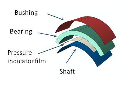
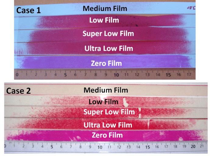
4 To this purpose, a pressure indicator film was employed. This pressure indicator film reveals the distribution and magnitude of pressure between two contacting, mating or impacting surfaces. The pressure indicating sensor film is sufficiently thin (0.2 mm) which enables it to conform to curved surfaces. It is suitable for tight spaces not accessible to conventional electronic transducers. The film is a Mylar based film that contains a layer of tiny microcapsules. The application of force upon the film causes the microcapsules to rupture, producing an instantaneous and permanent high resolution "topographical" image of pressure variation across the contact area [9]. By placing the film between two contacting bodies and applying and removing pressure, the film reveals the pressure distribution profile that occurred between the two surfaces. Conceptually similar to Litmus paper, the color intensity of the film is directly related to the amount of pressure applied to it. The greater the pressure, the more intense the color. In this test the pressure indicator film is used only to verify the area of the contact zone. Because each type of films can indicate a certain pressure range, five different films are used to explore the entire range of the contact pressure between the composite bearing and the shaft. Based on the indicating pressure level, the films are named as Zero, Ultra low, Super low, Low, and Medium film. The films are cut to strips, are assembled parallel to each other, and then are placed between the shaft and bearing. Two different tests are provided in this step. In the first test (case 1) the clearance between the bearing and shaft is 3.8 mm, and in the second test (case 2) the clearance is 0.82 mm. Figure 6 shows the test procedure, and table 3 depicts the details of the test conditions and the characteristics of the pressure indicator films. Test conditions Case 1 Case 2 Bearing diameter (mm) (mm) Bearing width 120 (mm) 60 (mm) Bearing thickness 25 (mm) 25 (mm) Shaft diameter 300 (mm) 300 (mm) Clearance 3.8 (mm) 0.82(mm) Vertical load 320 (kn) 56 (kn) Pressure indicator films Film name Indicating Pressure level Zero (MPa) Ultra low (MPa) Super low (MPa) Low (MPa) Medium (MPa) Table 3. Test conditions and different ranges that films can indicate Since the deformation of the bushing and shaft is negligible and here the evaluation of the contact stress distribution is the main objective, this experiment is simulated by a simplified finite element model shown in figure 7. This model includes a rigid shaft, rigid bushing, deformable composite bearing, and a deformable pressure indicator film. The pressure film is necessary to be included in the model because it changes the clearance between the bearing and shaft. The small free spaces between the pressure indicator films are not applied in the model, and the pressure sensor is simulated as a single strip. The vertical load is applied on the bushing, and the shaft is fixed. Figures 8 shows the experimental and numerical results for the contact stress distribution on the pressure indicating films. The maximum length of the colored areas on the pressure sensor films are 173 mm for case 1, and 209 mm for case 2, which are initiated on the zero film. These values are 170 and 204 mm for the simulation results (figure 10). Comparing these results gives a deviation less than 2 percent. Considering the scale of the test setup and parameters like geometrical tolerances, dimensional tolerances, loading misalignments, and other parameters this deviation is quite insignificant and results are in a very good agreement. Since in the contact modeling 2D
5 plane-strain elements correspond very well to 3D continuum elements [10], the agreement between the experiments and 3D simulations provides also approbation for the 2D models. 6. Influence of the clearance As seen in the previous section, the simulation results closely correspond to the experimental data. Based on these verifications, the finite element model is extended to investigate the effect of the clearance (play) between the composite bearing and the shaft on the kinematics of the setup and contact stresses on the bearing. The analyses were performed for the clearance ranges between 0.1 mm and 4.1 mm, with a step size of 0.4 mm. Even though the lower and upper bounds for the clearance are not practical choices, they are studied to evaluate the ratio of the clearance impact. Figure 9 shows the effect of the clearance size on the friction force. As seen, the clearance magnitude has not significant effect on the momentum of the friction force. While the magnitude of the friction force is not highly influenced by the clearance, figures 10 and 11 show that the frictional shear stress on the bearing is highly dependent on the clearance size. These figures show the distribution of the shear stress in the sliding condition while the shaft rotates in clockwise (CW) and counterclockwise (CCW) directions. By increasing the clearance size, the stress level increases and the contact area decreases. The effect of the clearance is more noticeable for the tighter clearances. By changing the clearance from 0.1 to 0.5, the maximum value of the shear stress increases about 0.26 MPa. Then, by increasing the clearance from 0.5 to 0.9, the maximum shear stress increase about 0.14 MPa. This value is about 0.1 MPa when the clearance changes from 0.9 to 1.3 mm. As expected, the normal pressure on the bearing shows the same behavior as the frictional shear stress. Figures 12 and 13 respectively show the normal pressure on the bearing surface for clockwise rotation of the shaft and counterclockwise rotation of the shaft. By changing the clearance from 0.1 mm to 4.1 mm, the maximum pressure changes about 8.2 MPa. Figure 14 shows the variation of the sliding angle by changing the clearance size. Like previous parameters, the clearance has a nonlinear effect on the sliding angle. The major effect is about 2 degrees for the play from 0.1 to 0.5. If the clearance becomes bigger than 1.3, the rolling angle does not change noticeably. Unlike the other parameters, the horizontal displacement of the busing is linearly dependent to the clearance size. In figure 15 it is seen that horizontal motion of the bushing increases about mm by adding 0.4 mm to the clearance. 7. Conclusion The application of a large scale polymeric composite journal bearing under the reciprocating angular movement has been studied. This study includes two major steps. At first, a polyester based composite bearing has been tested under 100 kn load. Besides the experimental investigations, a 2D finite element model has been built up to evaluate the kinematics of the setup and contact stresses on the bearing. The bearing has been simulated as an orthotropic material, and the static and dynamic friction conditions have been applied through an exponential function. Simulation results are in a very good agreement with the experimental outputs, and show that the combination of Lagrange and Euler formulations is a very convenient tool to simulate journal bearing applications. In the second step, a test has been planned to study the contact area between the bearing and the shaft. An arrangement of pressure indicator films has been used to measure the contact area. This test has also been simulated with a simplified 3D FEM model. The contact area obtained from the experiments and simulations, closely correspond and show that the FEM modeling results are highly reliable. Based on these verifications, the 2D FEM model is extended to investigate the effect of the clearance on the kinematics of the setup and contact stresses on the bearing. The results
6 show that the contact stress distribution is highly influenced by minor variation of the clearance, when the clearance is nominally small. Considering that the maximum contact stress is highly dependent on the clearance size and failure of the bearing is dependent on the stress level, it is very important to choose an appropriate clearance for composite journal bearings.
7 References [1] Friedrich K, Schlarb AK. Tribology of Polymeric Nanocomposites.Tribology and Interface Engineering Series, No. 55. first ed: Elsevier; [2] Barber JR, Ciavarella M. Contact mechanics. International Journal of Solids and Structures. 2000;37: [3] Papadopoulos CA, Nikolakopoulos PG, Gounaris GD. Identification of clearances and stability analysis for a rotor-journal bearing system. Mechanism and Machine Theory. 2008;43: [4] Pedersen P. On the influence of clearance in orthotropic disc-pin contacts. Composite Structures. 2007;79: [5] Rezaei A, Ost W, Paepegem WV, Degrieck J, Debaets P. Experimental study and numerical simulation of the large-scale testing of polymeric composite journal bearings: Two-dimensional modeling and validation. Tribology Letters. 2009;37:12. [6] Persson BNJ. Sliding friction: Physical principles and applications. 2nd edition ed: Springer; 1998 [7] Belytschko T, Liu WK, Moran B. Nonlinear Finite Elements for Continua and Structures John Wiley & Sons; [8] Oden JT, Martins JAC. Models and computational methods for dynamic friction phenomena. Computer Methods in Applied Mechanics and Engineering. 1985;52: [9] Pressurex. Tactile pressure indicating sensor film. 2010, January: [10] ABAQUS6.9 Documentation, Abaqus benchmarks manual, section
8 Figure captions Figure 1. Large-scale tribotester for radial composite bearings. Figure 2. Schematics of the forces and kinematics of the setup. a: Acting forces, b: Kinematics. Figure 3. 2D finite element model. Figure 4. Experimental measurements and numerical simulation results for the friction and normal forces between the composite bearing and shaft. Figure 5. Horizontal displacement of the bushing, Figure 6. Implementing of the pressure indicator films between the bearing and the shaft. Figure 7. 3D FE model for study of the contact area. Figure 8. Pressure distribution indicated by pressure sensor films and calculated with the FEM. Figure 9. Effect of the clearance on the friction force. Figure 10. Effect of the clearance on the frictional shear stress (clockwise rotation of the shaft). Figure 11. Effect of the clearance on the frictional shear stress (counterclockwise rotation of the shaft). Figure 12. Effect of the clearance on the normal stress (clockwise rotation of shaft). Figure 13. Effect of the clearance on the normal stress (counterclockwise rotation of shaft). Figure 14. Effect of the clearance on the sliding angle. Figure 15. Effect of the clearance on the horizontal displacement of the bushing.
9 Figure 1 1-Composite bearing 2-Bushing 3-Shaft 4-Shaft support 5-Drive piston 6-Drive lever arm 7-Bushing lever arm 8-load-cell(friction torque) 9-Hydraulic actuator 10-Load-cell (vertical load) 11-Load transmission trolley 12-Backing (Housing) 13-Shaft bushing
10 Figure 2 F P : Loading actuator force F F : Friction force F N : Normal force F L : Force on the load-cell R S : Shaft radius R b : Bearing radius R L : Distance between the action points of F P and F L α : Sliding angle (a) θ : Rotation of the shaft around the bearing s center φ : Rotation of the shaft around its own center β : Rotation of the bushing around the bearing s center x : Horizontal displacement of the bushing y : Vertical displacement of the bushing (b)
11 Figure 3
12 Figure 4
13 Figure 5
14 Figure 6
15 Figure 7
16 Figure 8
17 Figure 9
18 Figure 10
19 Figure 11
20 Figure 12
21 Figure 13
22 Figure 14
23 Figure 15
I-SUP 2008 April Evaluating self-lubricating materials for large scale bearings functioning under seawater conditions
 I-SUP 2008 April 23 2008 Evaluating self-lubricating materials for large scale bearings functioning under seawater conditions Van Autrève S., Ost W., Van Wittenberghe J. and De Baets P. 1 Application Civil
Dynamic Tests on Ring Shear Apparatus
 , July 1-3, 2015, London, U.K. Dynamic Tests on Ring Shear Apparatus G. Di Massa Member IAENG, S. Pagano, M. Ramondini Abstract Ring shear apparatus are used to determine the ultimate shear strength of
HELICAL BUCKLING OF DRILL-STRINGS
 HELICAL BUCKLING OF DRILL-STRINGS Marcin Kapitaniak 1,, Vahid Vaziri 1,, and Marian Wiercigroch 1 1 Centre for Applied Dynamics Research, School of Engineering, University of Aberdeen, Aberdeen, AB24 3UE,
INVESTIGATION OF FRICTION HYSTERESIS USING A LABORATORY- SCALE TRIBOMETER
 INVESTIGATION OF FRICTION HYSTERESIS USING A LABORATORY- SCALE TRIBOMETER P. D. Neis 1,2, P. De Baets 2, Y. Perez Delgado 2 and N. F. Ferreira 1 1 Federal University of Rio Grande do Sul, Brazil 2 Ghent
Stress Analysis Lecture 3 ME 276 Spring Dr./ Ahmed Mohamed Nagib Elmekawy
 Stress Analysis Lecture 3 ME 276 Spring 2017-2018 Dr./ Ahmed Mohamed Nagib Elmekawy Axial Stress 2 Beam under the action of two tensile forces 3 Beam under the action of two tensile forces 4 Shear Stress
ON NUMERICAL ANALYSIS AND EXPERIMENT VERIFICATION OF CHARACTERISTIC FREQUENCY OF ANGULAR CONTACT BALL-BEARING IN HIGH SPEED SPINDLE SYSTEM
 ON NUMERICAL ANALYSIS AND EXPERIMENT VERIFICATION OF CHARACTERISTIC FREQUENCY OF ANGULAR CONTACT BALL-BEARING IN HIGH SPEED SPINDLE SYSTEM Tian-Yau Wu and Chun-Che Sun Department of Mechanical Engineering,
Lubrication and Journal Bearings
 UNIVERSITY OF HAIL College of Engineering Department of Mechanical Engineering Chapter 12 Lubrication and Journal Bearings Text Book : Mechanical Engineering Design, 9th Edition Dr. Badreddine AYADI 2016
DEVELOPMENT OF A CONTINUUM PLASTICITY MODEL FOR THE COMMERCIAL FINITE ELEMENT CODE ABAQUS
 DEVELOPMENT OF A CONTINUUM PLASTICITY MODEL FOR THE COMMERCIAL FINITE ELEMENT CODE ABAQUS Mohsen Safaei, Wim De Waele Ghent University, Laboratory Soete, Belgium Abstract The present work relates to the
CHAPTER 6 FRICTION AND WEAR ANALYSIS FOR BUSHING
 CHAPTER 6 FRICTION AND WEAR ANALYSIS FOR BUSHING 6.1 TEST RIG SETUP FOR THE FRICTION AND WEAR ANALYSIS Knowing the frictional coefficient is important for the determination of wear loss and power loss
MODELING OF ELASTO-PLASTIC MATERIALS IN FINITE ELEMENT METHOD
 MODELING OF ELASTO-PLASTIC MATERIALS IN FINITE ELEMENT METHOD Andrzej Skrzat, Rzeszow University of Technology, Powst. Warszawy 8, Rzeszow, Poland Abstract: User-defined material models which can be used
D : SOLID MECHANICS. Q. 1 Q. 9 carry one mark each.
 GTE 2016 Q. 1 Q. 9 carry one mark each. D : SOLID MECHNICS Q.1 single degree of freedom vibrating system has mass of 5 kg, stiffness of 500 N/m and damping coefficient of 100 N-s/m. To make the system
CHAPTER 1 INTRODUCTION Hydrodynamic journal bearings are considered to be a vital component of all the rotating machinery. These are used to support
 CHAPTER 1 INTRODUCTION Hydrodynamic journal bearings are considered to be a vital component of all the rotating machinery. These are used to support radial loads under high speed operating conditions.
Torsion of Shafts Learning objectives
 Torsion of Shafts Shafts are structural members with length significantly greater than the largest cross-sectional dimension used in transmitting torque from one plane to another. Learning objectives Understand
MECHANICS OF MATERIALS
 2009 The McGraw-Hill Companies, Inc. All rights reserved. Fifth SI Edition CHAPTER 3 MECHANICS OF MATERIALS Ferdinand P. Beer E. Russell Johnston, Jr. John T. DeWolf David F. Mazurek Torsion Lecture Notes:
Study of Rupture Directivity in a Foam Rubber Physical Model
 Progress Report Task 1D01 Study of Rupture Directivity in a Foam Rubber Physical Model Rasool Anooshehpoor and James N. Brune University of Nevada, Reno Seismological Laboratory (MS/174) Reno, Nevada 89557-0141
Chapter 3. Load and Stress Analysis. Lecture Slides
 Lecture Slides Chapter 3 Load and Stress Analysis 2015 by McGraw Hill Education. This is proprietary material solely for authorized instructor use. Not authorized for sale or distribution in any manner.
Mechanical Properties of Materials
 Mechanical Properties of Materials Strains Material Model Stresses Learning objectives Understand the qualitative and quantitative description of mechanical properties of materials. Learn the logic of
Temperature analysis of a pin-on-disc tribology test using experimental and numerical approaches
 Friction 4(2): 135 143 (2016) ISSN 2223-7690 DOI 10.1007/s40544-016-0110-1 CN 10-1237/TH RESEARCH ARTICLE Temperature analysis of a pin-on-disc tribology test using experimental and numerical approaches
Experiment Two (2) Torsional testing of Circular Shafts
 Torsional testing of Circular Shafts") Experiment Two (2) Torsional testing of Circular Shafts Introduction: Torsion occurs when any shaft is subjected to a torque. This is true whether the shaft is rotating (such as drive shafts on engines,
Experiment Two (2) Torsional testing of Circular Shafts Introduction: Torsion occurs when any shaft is subjected to a torque. This is true whether the shaft is rotating (such as drive shafts on engines,
Transactions on Engineering Sciences vol 14, 1997 WIT Press, ISSN
 On the Computation of Elastic Elastic Rolling Contact using Adaptive Finite Element Techniques B. Zastrau^, U. Nackenhorst*,J. Jarewski^ ^Institute of Mechanics and Informatics, Technical University Dresden,
Transient Analysis of Disk Brake By using Ansys Software
 Transient Analysis of Disk Brake By using Ansys Software G. Babukanth & M. Vimal Teja Department of Mechanical Engineering, Nimra College of Engineering & Technology, Ibrahimpatnam, Vijayawada E-mail :
New Representation of Bearings in LS-DYNA
 13 th International LS-DYNA Users Conference Session: Aerospace New Representation of Bearings in LS-DYNA Kelly S. Carney Samuel A. Howard NASA Glenn Research Center, Cleveland, OH 44135 Brad A. Miller
Circular Bearing Performance Parameters with Isothermal and Thermo-Hydrodynamic Approach Using Computational Fluid Dynamics
 Circular Bearing Performance Parameters with Isothermal and Thermo-Hydrodynamic Approach Using Computational Fluid Dynamics Amit Chauhan 1 Department of Mechanical Engineering, University Institute of
( ) 5. Bearing internal load distribution and displacement. 5.1 Bearing internal load distribution
 5. Bearing internal load distribution and displacement. 5.1 Bearing internal load distribution") 5. internal load distribution and displacement 5. internal load distribution This section will begin by examing the effect of a radial load F r and an axial load F a applied on a single-row bearing with
5. internal load distribution and displacement 5. internal load distribution This section will begin by examing the effect of a radial load F r and an axial load F a applied on a single-row bearing with
Sliding Bearings. Fig.(1) (a) Full-journal bearing and (b) partial-journal bearing
 (a) Full-journal bearing and (b) partial-journal bearing") Sliding Bearings The goal of a bearing is to provide relative positioning and rotational freedom while transmitting a load between two parts, commonly a shaft and its housing. The object of lubrication
Sliding Bearings The goal of a bearing is to provide relative positioning and rotational freedom while transmitting a load between two parts, commonly a shaft and its housing. The object of lubrication
Physics 141 Rotational Motion 2 Page 1. Rotational Motion 2
 Physics 141 Rotational Motion 2 Page 1 Rotational Motion 2 Right handers, go over there, left handers over here. The rest of you, come with me.! Yogi Berra Torque Motion of a rigid body, like motion of
Effect of Angular movement of Lifting Arm on Natural Frequency of Container Lifting Mechanism using Finite Element Modal Analysis
 Effect of Angular movement of Lifting Arm on Natural Frequency of Container Lifting Mechanism using Finite Element Modal Analysis Khodu M Dhameliya, 2 Utpal V Shah, 3 Dhaval Makwana, 4 Mansi Yadav, 5 Ishankumar
M. Vable Mechanics of Materials: Chapter 5. Torsion of Shafts
 Torsion of Shafts Shafts are structural members with length significantly greater than the largest cross-sectional dimension used in transmitting torque from one plane to another. Learning objectives Understand
DEVELOP WEAR-RESISTANT POLYMERIC COMPOSITES BY USING NANOPARTICLES
 18 TH INTERNATIONAL CONFERENCE ON COMPOSITE MATERIALS DEVELOP WEAR-RESISTANT POLYMERIC COMPOSITES BY USING NANOPARTICLES 1 Abstract L. Chang 1 *, K. Friedrich 2 1 School of Aerospace, Mechanical & Mechatronic
Simulation of the Stick-Slip Friction between Steering Shafts Using ADAMS/PRE
 Simulation of the Stick-Slip Friction between Steering Shafts Using ADAMS/PRE Dexin Wang and Yuting Rui Research & Vehicle Technology Ford Motor Company ABSTRACT Cyclic stick-slip friction is a well-known
NUMERICAL MODELLING OF COMPOSITE PIN- JOINTS AND EXPERIMENTAL VALIDATION
 NUMERICAL MODELLING OF COMPOSITE PIN- JOINTS AND EXPERIMENTAL VALIDATION Fabrice PIERRON*, François CERISIER*, and Michel GRÉDIAC** * SMS/ Département Mécanique et Matériaux, École Nationale Supérieure
Strength Study of Spiral Flexure Spring of Stirling Cryocooler
 Sensors & Transducers 2013 by IFSA http://www.sensorsportal.com Strength Study of Spiral of Stirling Cryocooler WANG Wen-Rui, NIE Shuai, ZHANG Jia-Ming School of Mechanical Engineering, University of Science
Evaluation of Fault Foundation Interaction, Using Numerical Studies
 Evaluation of Fault Foundation Interaction, Using Numerical Studies Jabbary, M. Msc Student, School of Civil Engineering, Iran University of Science and Technology, Tehran, Iran, Nabizadeh, A. PhD Candidate,
Tuesday, February 11, Chapter 3. Load and Stress Analysis. Dr. Mohammad Suliman Abuhaiba, PE
 1 Chapter 3 Load and Stress Analysis 2 Chapter Outline Equilibrium & Free-Body Diagrams Shear Force and Bending Moments in Beams Singularity Functions Stress Cartesian Stress Components Mohr s Circle for
Dynamics of Machinery
 Dynamics of Machinery Two Mark Questions & Answers Varun B Page 1 Force Analysis 1. Define inertia force. Inertia force is an imaginary force, which when acts upon a rigid body, brings it to an equilibrium
S.C. Rulmenti S.A. Barlad Romania Republicii Street No
 SELECTION OF BEARING SIZE Basic load ratings The size of a bearing is selected considering the load in the used rolling bearing and also depends on the operational rating life and prescribed operating
SOLUTION (17.3) Known: A simply supported steel shaft is connected to an electric motor with a flexible coupling.
 Known: A simply supported steel shaft is connected to an electric motor with a flexible coupling.") SOLUTION (17.3) Known: A simply supported steel shaft is connected to an electric motor with a flexible coupling. Find: Determine the value of the critical speed of rotation for the shaft. Schematic and
SOLUTION (17.3) Known: A simply supported steel shaft is connected to an electric motor with a flexible coupling. Find: Determine the value of the critical speed of rotation for the shaft. Schematic and
Parameter Design of High Speed Coupling for 6 MW Wind Turbine Considering Torsional Vibration
 Parameter Design of High Speed Coupling for 6 MW Wind Turbine Considering Torsional Vibration JongHun Kang 1, Junwoo Bae 2, Seungkeun Jeong 3, SooKeun Park 4 and Hyoung Woo Lee 1 # 1 Department of Mechatronics
Online Calculation of Guide Rings for Hydraulic Cylinders
 Online Calculation of Guide Rings for Hydraulic Cylinders Fietz Roland Haraldsson Anna 1 Outline 1 2 3 4 5 6 7 Guide Rings General Information / Introduction Guide Rings Synthetic Materials Demarcation
Finite element prediction of the ultimate axial load capacity of V-section band clamps
 Journal of Physics: Conference Series Finite element prediction of the ultimate axial load capacity of V-section band clamps To cite this article: S M Barrans and M Muller 2009 J. Phys.: Conf. Ser. 181
A circular tunnel in a Mohr-Coulomb medium with an overlying fault
 MAP3D VERIFICATION EXAMPLE 9 A circular tunnel in a Mohr-Coulomb medium with an overlying fault 1 Description This example involves calculating the stresses and displacements on a fault overlying a 5 m
Modeling Method Analysis of the Friction Torque for High Speed Spindle Bearing
 MATEC Web of Conferences 75, 0308 (08) https://doi.org/0.05/matecconf/08750308 IFCAE-IOT 08 Modeling Method Analysis of the Friction Torque for High Speed Spindle Bearing Songsheng Li,, HuihangChen,, Haibing
Chapter 5 Torsion STRUCTURAL MECHANICS: CE203. Notes are based on Mechanics of Materials: by R. C. Hibbeler, 7th Edition, Pearson
 STRUCTURAL MECHANICS: CE203 Chapter 5 Torsion Notes are based on Mechanics of Materials: by R. C. Hibbeler, 7th Edition, Pearson Dr B. Achour & Dr Eng. K. El-kashif Civil Engineering Department, University
Dynamics of assembled structures of rotor systems of aviation gas turbine engines of type two-rotor
 Dynamics of assembled structures of rotor systems of aviation gas turbine engines of type two-rotor Anatoly А. Pykhalov 1, Mikhail А. Dudaev 2, Mikhail Ye. Kolotnikov 3, Paul V. Makarov 4 1 Irkutsk State
WORK SHEET FOR MEP311
 EXPERIMENT II-1A STUDY OF PRESSURE DISTRIBUTIONS IN LUBRICATING OIL FILMS USING MICHELL TILTING PAD APPARATUS OBJECTIVE To study generation of pressure profile along and across the thick fluid film (converging,
AP PHYSICS 1 Learning Objectives Arranged Topically
 AP PHYSICS 1 Learning Objectives Arranged Topically with o Big Ideas o Enduring Understandings o Essential Knowledges o Learning Objectives o Science Practices o Correlation to Knight Textbook Chapters
The basic dynamic load rating C is a statistical number and it is based on 90% of the bearings surviving 50 km of travel carrying the full load.
 Technical data Load Rating & Life Under normal conditions, the linear rail system can be damaged by metal fatigue as the result of repeated stress. The repeated stress causes flaking of the raceways and
Final Exam April 30, 2013
 Final Exam Instructions: You have 120 minutes to complete this exam. This is a closed-book, closed-notes exam. You are allowed to use a calculator during the exam. Usage of mobile phones and other electronic
STATIC AND DYNAMIC ANALYSIS OF A PUMP IMPELLER WITH A BALANCING DEVICE PART I: STATIC ANALYSIS
 Int. J. of Applied Mechanics and Engineering, 04, vol.9, No.3, pp.609-69 DOI: 0.478/ijame-04-004 STATIC AND DYNAMIC ANALYSIS OF A PUMP IMPELLER WITH A BALANCING DEVICE PART I: STATIC ANALYSIS C. KUNDERA
Mechanical Engineering Ph.D. Preliminary Qualifying Examination Solid Mechanics February 25, 2002
 student personal identification (ID) number on each sheet. Do not write your name on any sheet. #1. A homogeneous, isotropic, linear elastic bar has rectangular cross sectional area A, modulus of elasticity
ScienceDirect. Finite element analysis and optimization of flexure bearing for linear motor compressor
 Available online at www.sciencedirect.com ScienceDirect Physics Procedia 67 (2015 ) 379 385 25th International Cryogenic Engineering Conference and the International Cryogenic Materials Conference in 2014,
A novel fluid-structure interaction model for lubricating gaps of piston machines
 Fluid Structure Interaction V 13 A novel fluid-structure interaction model for lubricating gaps of piston machines M. Pelosi & M. Ivantysynova Department of Agricultural and Biological Engineering and
The University of Melbourne Engineering Mechanics
 The University of Melbourne 436-291 Engineering Mechanics Tutorial Eleven Instantaneous Centre and General Motion Part A (Introductory) 1. (Problem 5/93 from Meriam and Kraige - Dynamics) For the instant
Friction of Polymer/Steel Gear Pairs
 Friction of Polymer/Steel Gear Pairs Róbert KERESZTES, László ZSIDAI, Gábor KALÁCSKA, Mátyás ANDÓ and Rajmund LEFÁNTI Department of Maintenance of Machinery, Institute for Mechanical Engineering Technology
TE 75R RESEARCH RUBBER FRICTION TEST MACHINE
 TE 75R RESEARCH RUBBER FRICTION TEST MACHINE Background: The Research Rubber Friction Test Machine offers the ability to investigate fully the frictional behaviour of rubbery materials both in dry and
Cite this paper as follows:
 Cite this paper as follows: Naughton P.J. and O Kelly B.C. 2001. An overview of the University College Dublin hollow cylinder apparatus. Proceedings of the 14th Young European Geotechnical Engineer s Conference,
+ + = integer (13-15) πm. z 2 z 2 θ 1. Fig Constrained Gear System Fig Constrained Gear System Containing a Rack
 πm. z 2 z 2 θ 1. Fig Constrained Gear System Fig Constrained Gear System Containing a Rack") Figure 13-8 shows a constrained gear system in which a rack is meshed. The heavy line in Figure 13-8 corresponds to the belt in Figure 13-7. If the length of the belt cannot be evenly divided by circular
Figure 13-8 shows a constrained gear system in which a rack is meshed. The heavy line in Figure 13-8 corresponds to the belt in Figure 13-7. If the length of the belt cannot be evenly divided by circular
EMA 3702 Mechanics & Materials Science (Mechanics of Materials) Chapter 3 Torsion
 Chapter 3 Torsion") EMA 3702 Mechanics & Materials Science (Mechanics of Materials) Chapter 3 Torsion Introduction Stress and strain in components subjected to torque T Circular Cross-section shape Material Shaft design Non-circular
EMA 3702 Mechanics & Materials Science (Mechanics of Materials) Chapter 3 Torsion Introduction Stress and strain in components subjected to torque T Circular Cross-section shape Material Shaft design Non-circular
MECHANICS OF MATERIALS
 GE SI CHAPTER 3 MECHANICS OF MATERIALS Ferdinand P. Beer E. Russell Johnston, Jr. John T. DeWolf David F. Mazurek Torsion Lecture Notes: J. Walt Oler Texas Tech University Torsional Loads on Circular Shafts
VIBRATION ANALYSIS OF TIE-ROD/TIE-BOLT ROTORS USING FEM
 VIBRATION ANALYSIS OF TIE-ROD/TIE-BOLT ROTORS USING FEM J. E. Jam, F. Meisami Composite Materials and Technology Center Tehran, IRAN jejaam@gmail.com N. G. Nia Iran Polymer & Petrochemical Institute, Tehran,
ANALYSIS AND IDENTIFICATION IN ROTOR-BEARING SYSTEMS
 ANALYSIS AND IDENTIFICATION IN ROTOR-BEARING SYSTEMS A Lecture Notes Developed under the Curriculum Development Scheme of Quality Improvement Programme at IIT Guwahati Sponsored by All India Council of
The Torsion Pendulum (One or two weights)
") The Torsion Pendulum (One or two weights) Exercises I through V form the one-weight experiment. Exercises VI and VII, completed after Exercises I -V, add one weight more. Preparatory Questions: 1. The
The Torsion Pendulum (One or two weights) Exercises I through V form the one-weight experiment. Exercises VI and VII, completed after Exercises I -V, add one weight more. Preparatory Questions: 1. The
10/23/2015. Chapter 7. Velocity in Mechanisms. (Relative Velocity Method) Mohammad Suliman Abuhaiba, Ph.D., PE
 Mohammad Suliman Abuhaiba, Ph.D., PE") Chapter 7 Velocity in Mechanisms (Relative Velocity Method) 1 2 7.2. Relative Velocity of Two Bodies Moving in Straight Lines 3 7.3. Motion of a Link Velocity of any point on a link wrt another point on
Chapter 7 Velocity in Mechanisms (Relative Velocity Method) 1 2 7.2. Relative Velocity of Two Bodies Moving in Straight Lines 3 7.3. Motion of a Link Velocity of any point on a link wrt another point on
SUPPLEMENTARY INFORMATION
 SUPPLEMENTARY INFORMATION doi:10.1038/nature09348 This section provides supporting information for Reches and Lockner Fault weakening and earthquake instability by powder lubrication. The present topics
Scattered Energy of Vibration a novel parameter for rotating shaft vibration assessment
 5 th Australasian Congress on Applied Mechanics, ACAM 007 10-1 December 007, Brisbane, Australia Scattered Energy of Vibration a novel parameter for rotating shaft vibration assessment Abdul Md Mazid Department
EXPERIMENTAL RESEARCH REGARDING TRANSIENT REGIME OF KINEMATIC CHAINS INCLUDING PLANETARY TRANSMISSIONS USED IN INDUSTRIAL ROBOTS
 International Journal of Modern Manufacturing Technologies ISSN 2067 3604, Vol. VIII, No. 1 / 2016 EXPERIMENTAL RESEARCH REGARDING TRANSIENT REGIME OF KINEMATIC CHAINS INCLUDING PLANETARY TRANSMISSIONS
Analysis of dynamic characteristics of a HDD spindle system supported by ball bearing due to temperature variation
 Analysis of dynamic characteristics of a HDD spindle system supported by ball bearing due to temperature variation G. H. Jang, D. K. Kim, J. H. Han, C. S. Kim Microsystem Technologies 9 (2003) 243 249
Agricultural Science 1B Principles & Processes in Agriculture. Mike Wheatland
 Agricultural Science 1B Principles & Processes in Agriculture Mike Wheatland (m.wheatland@physics.usyd.edu.au) Outline - Lectures weeks 9-12 Chapter 6: Balance in nature - description of energy balance
Dynamics of Rotor Systems with Clearance and Weak Pedestals in Full Contact
 Paper ID No: 23 Dynamics of Rotor Systems with Clearance and Weak Pedestals in Full Contact Dr. Magnus Karlberg 1, Dr. Martin Karlsson 2, Prof. Lennart Karlsson 3 and Ass. Prof. Mats Näsström 4 1 Department
CYLINDRICAL ROLLER BEARINGS CARRYING THRUST LOAD
 CYLINDRICAL ROLLER BEARINGS CARRYING THRUST LOAD Gh. PRISACARU, Sp. CRETU, D. N. OLARU "Gh. Asachi Technical University, Department of Machine Design & Tribology, Bvd. D. Mangeron, 6-63, 66 Iasi, ROMANIA;
D : SOLID MECHANICS. Q. 1 Q. 9 carry one mark each. Q.1 Find the force (in kn) in the member BH of the truss shown.
 in the member BH of the truss shown.") D : SOLID MECHANICS Q. 1 Q. 9 carry one mark each. Q.1 Find the force (in kn) in the member BH of the truss shown. Q.2 Consider the forces of magnitude F acting on the sides of the regular hexagon having
D : SOLID MECHANICS Q. 1 Q. 9 carry one mark each. Q.1 Find the force (in kn) in the member BH of the truss shown. Q.2 Consider the forces of magnitude F acting on the sides of the regular hexagon having
Arbitrary Normal and Tangential Loading Sequences for Circular Hertzian Contact
 Arbitrary Normal and Tangential Loading Sequences for Circular Hertzian Contact Philip P. Garland 1 and Robert J. Rogers 2 1 School of Biomedical Engineering, Dalhousie University, Canada 2 Department
On Nonlinear Buckling and Collapse Analysis using Riks Method
 Visit the SIMULIA Resource Center for more customer examples. On Nonlinear Buckling and Collapse Analysis using Riks Method Mingxin Zhao, Ph.D. UOP, A Honeywell Company, 50 East Algonquin Road, Des Plaines,
Heat Transfer Analysis of Machine Tool Main Spindle
 Technical Paper Heat Transfer Analysis of Machine Tool Main Spindle oshimitsu HIRASAWA Yukimitsu YAMAMOTO CAE analysis is very useful for shortening development time and reducing the need for development
Investigation Of The Parameters Affecting Crankshaft And Rotor Interference Fit
 Purdue University Purdue e-pubs International Compressor Engineering Conference School of Mechanical Engineering 2014 Investigation Of The Parameters Affecting Crankshaft And Rotor Interference Fit Naz?m
Vector Mechanics: Statics
 PDHOnline Course G492 (4 PDH) Vector Mechanics: Statics Mark A. Strain, P.E. 2014 PDH Online PDH Center 5272 Meadow Estates Drive Fairfax, VA 22030-6658 Phone & Fax: 703-988-0088 www.pdhonline.org www.pdhcenter.com
Identification of interface properties using Fibre Bragg Grating sensors in a fibre pull-out test Gabriel Dunkel, Laurent Humbert and John Botsis
 Identification of interface properties using Fibre Bragg Grating sensors in a fibre pull-out test Gabriel Dunkel, Laurent Humbert and John Botsis Laboratory of Applied Mechanics and Reliability Analysis
The problem of transmitting a torque or rotary motion from one plane to another is frequently encountered in machine design.
 CHAPER ORSION ORSION orsion refers to the twisting of a structural member when it is loaded by moments/torques that produce rotation about the longitudinal axis of the member he problem of transmitting
INVESTIGATION OF BALL SCREWS FOR FEED DRIVE 1. INTRODUCTION
 Journal of Machine Engineering, Vol. 3, No. 4, 203 ball screws, machine tools, rigidity, impact forces Jerzy Z. SOBOLEWSKI INVESTIGATION OF BALL SCEWS FO FEED DIVE The paper presents a method which enables
The SKF model for calculating the frictional moment
 The SKF model for calculating the frictional moment The SKF model for calculating the frictional moment Bearing friction is not constant and depends on certain tribological phenomena that occur in the
DEPARTMENT OF MECHANICAL ENIGINEERING, UNIVERSITY OF ENGINEERING & TECHNOLOGY LAHORE (KSK CAMPUS).
.") DEPARTMENT OF MECHANICAL ENIGINEERING, UNIVERSITY OF ENGINEERING & TECHNOLOGY LAHORE (KSK CAMPUS). Lab Director: Coordinating Staff: Mr. Muhammad Farooq (Lecturer) Mr. Liaquat Qureshi (Lab Supervisor)
DEPARTMENT OF MECHANICAL ENIGINEERING, UNIVERSITY OF ENGINEERING & TECHNOLOGY LAHORE (KSK CAMPUS). Lab Director: Coordinating Staff: Mr. Muhammad Farooq (Lecturer) Mr. Liaquat Qureshi (Lab Supervisor)
A nonlinear dynamic vibration model of defective bearings: The importance of modelling the finite size of rolling elements
 A nonlinear dynamic vibration model of defective bearings: The importance of modelling the finite size of rolling elements Alireza Moazenahmadi, Dick Petersen and Carl Howard School of Mechanical Engineering,
Contact problems in rotor systems
 Contact problems in rotor systems Liudmila Banakh Mechanical Engineering Research Institute of RAS, Moscow, Russia E-mail: banl@inbox.ru (Received 18 July 2016; accepted 24 August 2016) Abstract. We consider
3.5 STRESS AND STRAIN IN PURE SHEAR. The next element is in a state of pure shear.
 3.5 STRESS AND STRAIN IN PURE SHEAR The next element is in a state of pure shear. Fig. 3-20 Stresses acting on a stress element cut from a bar in torsion (pure shear) Stresses on inclined planes Fig. 3-21
Computation of magnetic field in an actuator
 Computation of magnetic field in an actuator A. G. Olabi and A. Grunwald Dublin City University, School of Mechanical and Manufacturing Engineering, Glasnevin, Dublin 9, Ireland, Email: abdul.olabi@dcu.ie,
Chapter 9. Rotational Dynamics
 Chapter 9 Rotational Dynamics In pure translational motion, all points on an object travel on parallel paths. The most general motion is a combination of translation and rotation. 1) Torque Produces angular
Overview. Dry Friction Wedges Flatbelts Screws Bearings Rolling Resistance
 Friction Chapter 8 Overview Dry Friction Wedges Flatbelts Screws Bearings Rolling Resistance Dry Friction Friction is defined as a force of resistance acting on a body which prevents slipping of the body
Arch. Metall. Mater. 62 (2017), 1, 85-90
, 1, 85-90") Arch. Metall. Mater. 62 (2017), 1, 85-90 DOI: 10.1515/amm-2017-0011 Z. PATER* # FEM ANALYSIS OF LOADS AND TORQUE IN A SKEW ROLLING PROCESS FOR PRODUCING AXISYMMETRIC PARTS Skew rolling is a metal forming
Arch. Metall. Mater. 62 (2017), 1, 85-90 DOI: 10.1515/amm-2017-0011 Z. PATER* # FEM ANALYSIS OF LOADS AND TORQUE IN A SKEW ROLLING PROCESS FOR PRODUCING AXISYMMETRIC PARTS Skew rolling is a metal forming
MECHANICS OF MATERIALS
 Third E CHAPTER 2 Stress MECHANICS OF MATERIALS Ferdinand P. Beer E. Russell Johnston, Jr. John T. DeWolf Lecture Notes: J. Walt Oler Texas Tech University and Strain Axial Loading Contents Stress & Strain:
Friction in Anti-friction Bearings
 Tribology Prof. Dr. Harish Hirani Department of Mechanical Engineering Indian Institute of Technology, Delhi Lecture No. # 32 Friction of Rolling Element Bearing Welcome to thirty second lecture of video
CIVL222 STRENGTH OF MATERIALS. Chapter 6. Torsion
 CIVL222 STRENGTH OF MATERIALS Chapter 6 Torsion Definition Torque is a moment that tends to twist a member about its longitudinal axis. Slender members subjected to a twisting load are said to be in torsion.
Example-3. Title. Description. Cylindrical Hole in an Infinite Mohr-Coulomb Medium
 Example-3 Title Cylindrical Hole in an Infinite Mohr-Coulomb Medium Description The problem concerns the determination of stresses and displacements for the case of a cylindrical hole in an infinite elasto-plastic
EXPERIMENTAL EVALUATION OF SHEAR STRENGTH OF WOVEN WEBBINGS
 EXPERIMENTAL EVALUATION OF SHEAR STRENGTH OF WOVEN WEBBINGS Kevin L. Peil +, Ever J. Barbero +, Eduardo M. Sosa* + Department of Mechanical and Aerospace Engineering, West Virginia University (WVU), Morgantown,
Expansion of circular tubes by rigid tubes as impact energy absorbers: experimental and theoretical investigation
 Expansion of circular tubes by rigid tubes as impact energy absorbers: experimental and theoretical investigation M Shakeri, S Salehghaffari and R. Mirzaeifar Department of Mechanical Engineering, Amirkabir
STATICS & DYNAMICS. Engineering Mechanics. Gary L. Gray. Francesco Costanzo. Michael E. Plesha. University of Wisconsin-Madison
 Engineering Mechanics STATICS & DYNAMICS SECOND EDITION Francesco Costanzo Department of Engineering Science and Mechanics Penn State University Michael E. Plesha Department of Engineering Physics University
Self-weight loading of horizontal hydraulic cylinders with axial load
 Journal of Physics: Conference Series PAPER OPEN ACCESS Self-weight loading of horizontal hydraulic cylinders with axial load Related content - Stability analysis of large slenderness ratio horizontal
BIAXIAL STRENGTH INVESTIGATION OF CFRP COMPOSITE LAMINATES BY USING CRUCIFORM SPECIMENS
 BIAXIAL STRENGTH INVESTIGATION OF CFRP COMPOSITE LAMINATES BY USING CRUCIFORM SPECIMENS H. Kumazawa and T. Takatoya Airframes and Structures Group, Japan Aerospace Exploration Agency 6-13-1, Ohsawa, Mitaka,
file:///d /suhasini/suha/office/html2pdf/ _editable/slides/module%202/lecture%206/6.1/1.html[3/9/2012 4:09:25 PM]
![file:///d /suhasini/suha/office/html2pdf/ _editable/slides/module%202/lecture%206/6.1/1.html[3/9/2012 4:09:25 PM]](/thumbs/96/126781421.jpg "file:///d /suhasini/suha/office/html2pdf/ _editable/slides/module%202/lecture%206/6.1/1.html[3/9/2012 4:09:25 PM]") Objectives_template Objectives In this section you will learn the following Introduction Different Theories of Earth Pressure Lateral Earth Pressure For At Rest Condition Movement of the Wall Different
Objectives_template Objectives In this section you will learn the following Introduction Different Theories of Earth Pressure Lateral Earth Pressure For At Rest Condition Movement of the Wall Different
Design of a fastener based on negative Poisson's ratio foam adapted from
 1 Design of a fastener based on negative Poisson's ratio foam adapted from Choi, J. B. and Lakes, R. S., "Design of a fastener based on negative Poisson's ratio foam", Cellular Polymers, 10, 205-212 (1991).
7.6 Journal Bearings
 7.6 Journal Bearings 7.6 Journal Bearings Procedures and Strategies, page 1 of 2 Procedures and Strategies for Solving Problems Involving Frictional Forces on Journal Bearings For problems involving a