|
|
|
- Jesse Weaver
- 6 years ago
- Views:
Transcription
1
2

3

4
5


6


7
8

9
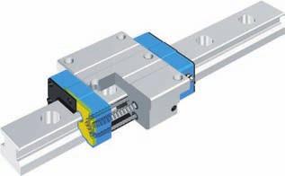
10 Identification The of -Lube Linear Roller Way Super MX is identified by the identification, which consists of model code, size, part code, material symbol preload symbol, classification symbol, interchangeable code and optional supplemental codes. xamples of identification Slide unit only MX G 1 T1 P S2 /Z 1 Series Flange type, and bottom : MX 1 Block type, : MXD ompact block type, : MXS Low section flange type, : MX Low section block type, : MXS Track rail only 1 LRX R2 P S2 /F Assembled set on-interchangeable Matched set product Series Length type of slide unit Size of rolling guide umber of slide unit Length of track rail Material code Size Part code Material symbol Preload Preload symbol Accuracy class Optional lassification symbol code Supplemental code ote 1 : When ordering track rail only, model code should be changed as shown below. MX / MXD / MXS LRX (x: LRXR2HS2 MX G 2 R2 T1 P S2 /FZ MX G 2 R2 T1 P /FZ 2 Length type of slide unit Short Standard High rigidity long xtra high rigidity long 3 Size of rolling guide Standard MXS Low section block type, High rigidity long MXSG xtra high rigidity long MXSL Stainless Steel Block type, Standard MXDSL ote 1 : MX, MX, MXG and MXL can be mounted from top side only. For mounting from bottom, MXH, MXH, MXHG and MXHL can be used. Remark : marks are also applicable for interchangeable. Available types and size are shown in Table 1 below. ote 1 : Size (MX, MXD and MXS can be mounted from top only. MXH can be mounted from bottom, which has the same dimensions as those of above models. : : o symbol : G : L,, 2,, 3,,, Available types and size are shown in Table 1 below. Table 1 Types and sizes of -Lube Linear Roller Way Super MX Material High arbon Steel Type Flange type, and bottom Block type, ompact Block type, Low section flange type, Short Standard Mode code xtra high rigidity long Short xtra high rigidity long Short xtra high rigidity long Standard xtra high rigidity long MX MX High rigidity long MXG Standard MXL MXD MXD High rigidity long MXDG Standard MXDL MXS MXS High rigidity long MXSG MXSL MX High rigidity long MXG MXL Available types and size are shown in Table 1 below. Size = 0.2kgf = 0.22lbs. 1 = 0.033inch 1 1
11 Identification Accuracy Preload umber of slide unit Matched set product (with track rail Slide unit only ( series Length of track rail Matched set product (with slide unit Track rail only ( series Material Preload Accuracy code Optional s High carbon steel Stainless steel Standard Light preload Medium preload Heavy preload High class Precision class Super precision class Ultra precision class : (x : MX2R2H : 1 (x : MX1HS2 : R (x:mx2r2h : R (x:lrxr2h2 : o symbol : SL : o symbol : T1 : T2 : T3 : H : P : SP : UP : S2 /A, /D, /, /F, /G, /HP, /1, /J, /L, /LF, /MA, /M, /, /R, /T, /UR, /V, /W, /Z For a matched set, indicates the of slide units assembled on one track rail. For an interchangeable slide unit only, 1 can be indicated. Indicate the length of track rail in. For standard and maximum lengths, see Track rail length in Table 22.1, 22.2, 22.3 and 22. on page 3. For applicable model and size, see Table 1 on page 1. Specify preload for a matched set or an interchangeable single slide unit. Details of preload amount and applicable sizes are shown in Table 3 on page. Super precision class (SP and Ultra precision class (UP are applicable to on-interchangeable products only. In the interchangeable, please combine the same accuracy codes on both slide unit and track rail. For details of accuracy, see Table 2 on page. In -Lube Linear Roller Way, slide unit and track rail can be supplied separately by indicating interchangeable code S2. Applicable special s are shown in Table on page 21. When a combination of several special s is required, arrange supplemental codes in alphabetical order. For detail of special s, see page 21 to 2. Accuracy for the matched set of -Lube Linear Roller Way Super MX are shown in Table 2. Table 2 Accuracy of -Lube Linear Roller Way Super MX A H lassification (Symbol Item Dim. H Tolerance Dim. Tolerance Dim. variation of H 2 Dim. variation of 2 Dim. variation of H 3 for multiple sets Parallelism in operation of to A Parallelism in operation of D to B ote 1 : 2 : D B High H Precision P Super 1 precision SP Refer to Fig. 1 Refer to Fig. 1 unit : Ultra 1 precision UP Applicable to on-interchangeable. Dimensional variation of dimension means the size variation among the slide units mounted on the same track rail when the dimension H is measured at the same measuring position of track rail. 3 : Applicable to interchangeable Remark 1 : These values also apply to -Lube Linear Roller Way Super MX series that has opposite reference surface arrangements. 2: Dimensional variation of dimension H for multiple sets means the variation of dimension H among multiple sets of arbitrarily chosen slide unit and track rail of -Lube Linear Roller Way Super MX series. 3: All of above figures are applicable when the dimensions are measured at the center of each slide unit assembled with a track rail fixed onto a flat base. Average amounts of preload for -Lube Linear Roller Way Super MX series are shown in Table 3. ote that, for the slide unit of interchangeable, the preload amounts that can be specified are different depending on the size. Applicable preload class and size are shown in Table. In case high rigidity and/or damping characteristic might be required, the preload amount is recoended to be 1/2 of the external force. Table 3 Preload amount Item Preload Preload Symbol amount Typical application class Standard preloado symbol 0 1 Smooth and precise motion Minimum vibration Light preload T Loads equally balanced Smooth and precise motion Medium vibration Medium preload T Medium overhung load Vibration and/or shocks Heavy preload T Large overhung load Heavy cutting ote 1 : Zero or minimal amount of preload. Remark : 0 means the basic static load rating. Table Applicable preload class Preload class and code code Standard o symbol Light preload T1 Medium preload T2 Heavy preload T3 MX MX MX 2 MX MX 3 MX MX MX Remark 1 : marks are also applicable for interchangeable. 2: The table shows representative model s and is also applicable to all models in the same size. Parallelism m High (H Precision (P Super precision (SP Ultra precision (UP Length of track rail L Fig. 1 Parallelism in operation 1 = 0.2kgf = 0.22lbs. 1 = 0.033inch 1
12 Optional special s for the use under special environment -Lube Linear Roller Way Super MX with optional s shown in Table are optionally available for various applications. When ordering, add any supplemental codes onto the identification. If multiple optional s are required, indicate Table Applicable optional s Specifications Supplemental code Slide unit only Track rail only Set product Butt jointing track rail Opposite reference surfaces arrangement Specified rail mounting hole positions aps for rail mounting holes Different pitch of slide unit middle row mounting holes Half pitch of track rail mounting holes Append an inspection sheet Female threads for bellow mounting Black chrome surface treatment Fluoric black chrome surface treatment With track rail mounting bolts Without track rail mounting bolts o rubber end seals -Wipers Butt-jointing interchangeable track rail Inner seals Double end seals Matched sets to be used as an assembled group Scrapers /A /D / /F /G /HP /1 /J /L /LF /MA /M / /R /T /UR /V /W /Z ote 1 : Applicable to MX, MXG, MXH and MXHG. 2 : ot applicable to stainless steel type. 3 : ot applicable to low section frange and block type, and size and. : /R includes Inner seal and Scraper. /UR and /Z are not necessary. : ot applicable to size and. Table ombination of supplemental codes D F G HP 1 J L LF MA M R T UR V W Z A D F G HP 1 J L LF MA M R T the supplemental codes in alphabetical order. These optional items can be combined to achieve further improvement of performance. Please refer Table for combination detail. on-interchangeable 1 3 Remark 1 : marks indicate that the combination can be made. 2: marks are also applicable for interchangeable. 3: marks indicate that the combination is not available. : If the combination of marks are required, please consult. : If a combination of optional s is required, indicate the supplemental codes in alphabetical order. : /R includes /UR and /Z as standard. UR V W Butt jointing track rails -A1 -B1 -A1 -B1 When the required length of non-interchangeable track rail exceeds the maximum length shown in Table 22.1 and 22.3 on page 3, two or more track rails can be used by butt jointing. For the length of each rails and the of butt jointing track rails, please consult. Reference mounting surface of slide unit -A2 -B2 -A2 -B2 Opposite reference surfaces arrangement Reference mounting surface of track rail Specified track rail mounting hole positions mark /A /D The reference mounting surface of track rail is made opposite to the standard side. The accuracy of dimension including parallelism in operation is the same to that of standard. / The position of the first mounting hole from left end of the track rail (dimension can be specified. When ordering, add the dimension (in after /. Dimension can be specified in a limited range. onsult for further information. If long dimension is required, imperfect mounting hole may remain. aps for rail mounting holes L aps (Made of synthetic resin Specify to have customized caps for track rail mounting holes appended. These caps cover the track rail mounting holes to improve the sealing performance in the linear motion direction. Aluminum caps are also available. onsult for further information. L /F Different pitch of slide unit middle row mounting holes /G A with different pitch length between the two middle mounting holes of slide unit. For the dimension, see Table. Table Pitch of slide unit middle mounting holes (Supplemental code /G MX, MXG MX, MXG 1 MX2, MXG2 MX, MXG 2 MX3, MXG3 2 MX, MXG 0 MX, MXG MX, MXG 1 ote 1 : Also applicable to MXH(G 1 = 0.2kgf = 0.22lbs. 1 = 0.033inch L unit :
13 Optional special s for the use under special environment Half pitch of track rail mounting holes /2 F F/2 The pitch of the track rail mounting holes can be 1/2 of the dimension F of standard rail. Track rail mounting bolts are appended in the same as that of mounting holes. With inspection sheet Slide unit Female threads for bellows Track rail /HP This designates to attach an inspection sheet with the product that is recording dimensions H and (See Accuracy, dimensional variations of H and and parallelism in operation of the slide unit. With female threads for bellow mounting /J /JR /JL Female threads for mounting bellows are provided on the interchangeable slide unit or the interchangeable track rail. For details of related dimensions, see Table.1,.2 and.3 on page 2 to 2. q /J Female threads are provided at both ends of the slide unit or the track rail. w /JR Female threads are provided at the right end of the slide unit in sight of mark. e /JL Female threads are provided at the left end of the slide unit in sight of mark. With female threads for bellow mounting (for an assembled set /J /JJ /JR /JS /JJS Female threads for bellows Female threads for bellows For an assembled set of interchangeable or non-interchangeable, female threads for mounting bellows are provided on the slide unit and the track rail. For details of related dimensions, see Table.1,.2 and.3 on page 2 to 2. q /J Female threads are provided on both ends of the track rail and on the slide unit ends which are the closest to the track rail ends. (In case only one slide unit is assembled, female threads are provided on both ends. w /JJ Female threads are provided on both ends of the track rail and on all ends of all slide units. (Applicable when the of slide units to be two or more. In case only one slide unit is assembled, indicate /J. e /JR Female threads are provided on both ends of the track rail. r /JS Female threads are provided on the slide unit ends which are the closest to the track rail ends. (In case only one slide unit is assembled, female threads are provided on both ends. t /JJS Female threads are provided on all ends of all slide units. (Applicable when the of slide units to be two or more. In case only one slide unit is assembled, indicate /JS. Black chrome surface treatment /L /LR /LR A black permeable chrome film is formed to improve corrosion resistance. q /L Treatment is applied to the casing. w /LR Treatment is applied to the track rail. e /LR Treatment is applied to the casing and the track rail. Fluorine black chrome surface treatment /LF /LFR /LFR After forming black permeable chrome film, the surface is coated with fluorine resin for further improvement in corrosion resistance. This treatment is also effective in preventing the adhesion of foreign substances on the surface. q /LF Treatment is applied to the casing. w /LFR Treatment is applied to the track rail. e /LFR Treatment is applied to the casing and the track rail. Table.1 Female threads for bellow mounting (Supplemental code /J, /JJ Size to a 1 D b 1 b 2 b 1 b 2 B Flange type MX MX MXG MXD MXD MXDG MXS MXS MXSG MX MXH MX MXH MXG MXHG MX0 MXH0 MXD MXD MXDG MXD0 MXS MXS MXSG MXS0 MX 2 MX 2 MXG 2 MX MXD 2 MXD 2 MXDG 2 MXD MXS 2 MXS 2 MXSG 2 MXS MX MX MXG MXL MXD MXD MXDG MXDL MXS MXS MXSG MXSL 2M 1 depth H 3 a 3 a 2M 2 depth a b a 1 D B 2M 1 depth H 3 a 3 a 2M 2 depth Block type, ompact Block type Slide unit M 1 depth b Grease nipple 1 AM3 L 1 Track rail ote 1 : The and mounting position of grease nipple are different from those of standard products. Grease nipple A-M is attached to size. For grease nipple, see Table 1 on page : The values for the slide unit with female threads for bellow mounting at the both ends. Remark 1 : Also applicable to same size of stainless steel products. 2: For the size and of flange type and compact block type, the dimension a is higher than H dimension. For details, consult for future information. M3 M3 M3 M3 L H a 3 a 1 unit : M 2 depth M3 M M M 1 = 0.2kgf = 0.22lbs. 1 = 0.033inch 23 2
14 Optional special s for the use under special environment Table.2 Female threads for bellow mounting (Supplemental code /J, /JJ Table.3 Female threads for bellow mounting (Supplemental code /J, /JJ Size 3 to b 3 b M 1 depth b 3 b M 1 depth L 1 a 2 a 1 b 3 b M 1 depth b 3 b b 1 b 2 a 2 a 1 b 1 b 2 M 1 depth L 1 b 1 b 2 a 2 a 1 a a 2 a 1 b 1 b 2 a D MX 3 MX 3 MXG 3 MX MXD 3 MXD 3 MXDG 3 MXD MX MX MXG MXL MXD MXD MXDG MXDL MX MX MXG MXL MXD MXD MXDG MXDL MX MX MXG MXL MXD MXD MXDG MXDL B a a 3 2M 2 depth D B a a 3 2M 2 depth Flange type Block type unit : Slide unit Track rail a 1 a 2 b 1 b 2 b 3 b M 1 depth L 1 1 a 3 a M 2 depth M M M M M 1 2 M M M ote 1 : The values are of the slide unit with female threads for bellow mounting at the both ends. a 2 a 2 a 1 D D D B B B b 3 b b 1 b 2 b 3 b b 1 b 2 a 3 2M 2 depth Size 3 Size 3 M 1 depth a a 3 2M 2 depth 2M 2 depth M 1 depth a a 3 a 2 a 2 a 1 D D D B B B b 3 b b 1 b 2 Size Size b 3 b b 1 b 2 Size Size a 3 2M 2 depth 2M 2 depth M 1 depth a a 3 2M 2 depth M 1 depth Low section flange type Low section block type unit : Slide unit Track rail a 1 1 a 2 b 1 b 2 b 3 b M 1 depth 1 a 3 a M 2 depth MX MXG 3 MX M3 MXS M MXSG 3 MXS 11 MX 13 MXG MXL M MXS 13 1 M MXSG 1 3 MXSL 23 MX 13 MXG 2 2 MXL M MXS 13 2 M MXSG 2 MXSL 1 ote 1 : Values a 1 are the dimension between -surface (upper surface of slide unit and the center of female thread. 2 : The values for the slide unit with female threads for bellow mounting at the both ends. Remark : The dimension a is higher than H dimension. For details, consult for future information. a a 3 1 = 0.2kgf = 0.22lbs. 1 = 0.033inch 2 2
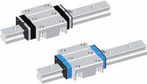
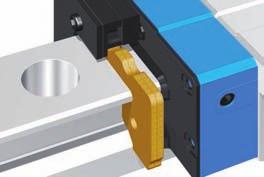
15 Optional special s for the use under special environment With track rail mounting bolts -Wipers nd pressure plate -Wipers /MA Track rail mounting bolts are not appended for the assembled set products (both interchangeable and non-interchangeable s. /MA designates to append the bolts according to the of mounting holes. For size of bolts, please refer dimension tables. Without track rail mounting bolts /M Track rail mounting bolts are not appended by /M. This is applicable to interchangeable track rail only. o end seal / nd rubber seals at both ends of slide unit are replaced by steel end plates (not in contact with the track rail to reduce frictional resistance. The under seals are not assembled in this case and this is not effective for dust protection. /R /R -Wipers are attached on the slide unit for additional dust protection. The slide unit with -Wipers has also Inner Seal (/UR and Scraper. Total lengths of slide unit with -Wipers are shown in Table.1 and.2. q /R -Wipers are provided at the ends of slide units which are closest to the end of the track rail. In case only one slide unit is assembled, -Wipers are provided at the both ends of slide unit. w /R -Wipers are provided at both ends of all slide units. Applicable when the of slide units to be two or more. In case one slide unit, indicate /R. Table.1 Slide unit with -Wipers (Supplemental code /R /R Size 2 and L L 1 unit : L 1 1 L 1 MX 2 MX 2 3 MXG 2 13 MX 2 MX 0 MX 11 MXG 1 MXL 1 ote 1 : The values for the slide unit with -Wipers at both ends. Remark : The table shows representative model s only and is also applicable to all models in the same size. Table.2 Size 3 to Slide unit with -Wipers (Supplemental code /R /R -Wiper MX 3 MX 3 MXG 3 MX MX MX MXG MXL MX MX MXG MXL MX MX MXG MXL L 1 -Wiper L unit : ote 1 : The values for the slide unit with -Wipers at both ends. Remark : The table shows representative model s only and is also applicable to all models in the same size. Butt-jointing interchangeable track rail (for interchangeable Inner seals With double end seals (for interchangeable single slide unit With double end seals (for assembled set nd seal Spacer Inner seals /T A special interchangeable track rail of which both ends are finished for butt jointing. Use the track rails having the same interchangeable code for butt jointing. For the butt jointing of non-interchangeable, indicate "butt-jointing track rail /A. /UR Inner seals are provided inside of slide unit, where recirculation area is effectively protected from dust collected on upper surface of track rail. /V /VR /VL Double rubber end seals are provided on the interchangeable slide unit for more effective dust protection. For the total length of the slide unit with double end seals, see the Table.1 and.2. q /V Double end seals are provided at both ends of the slide unit. w /VR Double end seals are provided at the right end of the slide unit in sight of mark. e /VL Double end seals are provided at the left end of the slide unit in sight of mark. /V /VV Double end seals are provided on the slide unit of assembled set of interchangeable or non-interchangeable (set for more effective dust protection. For the total length of the slide unit with double end seals, see the Table.1 and.2. q/v Double end seals are provided at the ends of slide units which are the closest to the ends of the track rail. (In case only one slide unit is assembled, double end seals are provided at both ends. w/vv Double end seals are provided at all ends of all slide units. (Applicable when the of slide units to be two or more. In case only one slide unit is assembled, indicate /V. Table.1 Slide unit with double end seals (Supplemental code /V, /VV Size to nd seal nd seal L L 1 L 1 nd seal unit : L 1 1 L 1 MX MX MXG 0 2 MX 3 3 MX 3 3 MXG 3 MX0 13 MX MX 2 11 MXG MX 1 MX 3 MX 1 13 MXG MXL ote 1 : The values for the slide unit with double end seals at both ends. Remark : The table shows representative model s only and is also applicable to all models in the same size. Table.2 Slide unit with double end seals (Supplemental code /V, /VV Size 3 to nd seal unit : L 1 1 MX 3 1 MX MXG 3 11 MX 13 MX MX 1 MXG MXL 2 MX 1 MX 1 MXG 21 MXL MX MX 2 MXG 3 MXL 32 ote 1 : The values for the slide unit with double end seals at both ends. Remark : The table shows representative model s only and is also applicable to all models in the same size. 1 = 0.2kgf = 0.22lbs. 1 = 0.033inch 2 2
16 Optional special s for the use under special environment Load ratings and Life Matched sets to be used as an assembled group /W H Set a Set b H Table 11.1 Slide unit with scrapers (Supplemental code, /Z /ZZ Size to Scraper L L 1 Scraper Basic dynamic load rating onforming to ISO 12-1 The basic dynamic load rating is defined as a constant load both in direction and magnitude under which a group of identical -Lube Linear Roller Way Super MX is individually operated and 0% of those in the group can travel 0 3 m free from material damage due to rolling contact fatigue. Upward load Downward load For two or more assembly sets of -Lube Linear Roller Way Super MX used on the same plane, the dimensional variation of H are kept within the specified range. The dimensional variation of dimension H in matched sets is the same as that of a single set. Indicate the of sets after /W. With scrapers (for interchangeable single slide unit With scrapers (for assembled set Scraper /Z /ZR /ZL Metal scrapers are provided on the slide unit of interchangeable. Scrapers (non-contact type are attached to effectively remove large particles of dust or foreign matters adhering to the track rail. For the total length of the slide unit with scrapers, see Table 11.1 and q /Z Scrapers are provided at both ends of the slide unit. w /ZR A scraper is provided at the right end of the slide unit in sight of mark. e /ZL A scraper is provided at the left end of the slide unit in sight of mark. /Z /ZZ unit : L 1 1 L 1 MX 1 MX MXG 2 3 MX 3 MX 3 MXG 11 3 MX MX 2 3 MX 2 11 MXG MX 1 MX MX 13 MXG MXL 13 1 ote 1 : The values are the slide unit lengths with scrapers at both ends. Remark : The table shows representative model s and is also applicable to all models in the same size of MX series. Table 11.2 Slide unit with scrapers (Supplemental code, /Z /ZZ Size 3 to Scraper L 1 Scraper Basic static load rating 0 onforming to ISO 12-2 The basic static load rating is defined as a static load that gives a prescribed constant contact stress at the center of the contact area between rolling elements and raceways receiving the maximum load. Generally, the basic static load rating is used in combination with the static safety factor. The static load ratings of -Lube Linear Roller Way Super MX are designated for equal load capacity in downward load, upward load and lateral load. Static moment rating T 0,, The static moment rating is defined as a static moment load (See Fig. 3 that gives a prescribed constant contact stress at the center of the contact area between rolling elements and raceways receiving the maximum load. The static moment rating is used in combination with the static safety factor to give the limiting load for normal rolling motion. Generally, the basic static moment rating is used in combination with the static safety factor. Fig. 2 Load directions Lateral load nd seal Spacer Metal scrapers are provided on the slide units of assembled set of interchangeable or non-interchangeable (set. Scrapers (non-contact type are attached to effectively remove large particles of dust or foreign matters adhering to the track rail. For the total length of the slide unit with scrapers, see Table 11.1 and q /Z Scrapers are provided at the ends of slide units which are the closest to the ends of the track rail. (In case only one slide unit is assembled, scrapers are provided at both ends. w /ZZ Scrapers are provided at all ends of all slide units. (Applicable when the of slide units to be two or more. In case only one slide unit is assembled, indicate /Z. unit : L 1 1 MX 3 3 MX 3 13 MXG 3 13 MX MX MX 1 MXG MXL 2 MX 1 MX 1 MXG 23 MXL MX 1 MX 2 MXG 322 MXL 32 ote 1 : The values are the slide unit lengths with scrapers at both ends. Remark : The table shows representative model s and is also applicable to all models in the same size of MX series. T 0 Fig. 3 Directions of static moment rating 1 = 0.2kgf = 0.22lbs. 1 = 0.033inch 2
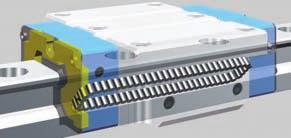
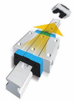
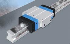
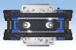
17 Load ratings and Life Lubrication and dust protection Life The rating life of -Lube Linear Roller Way Super MX series is obtained from the following calculation formula. L = 0( P where, L : Rating life, 3 m : Basic dynamic load rating, P : quivalent load, If the stroke length and the or strokes per minute are known, the life in hours must be corrected by the following formula. L h = L 2Sn 1 where, L h : Rating life in hours, hours S : Stroke length, : umber of strokes per minute, cpm n 1 /3 1 Static safety factor 2 The static safety factor f S of -Lube Linear Roller Way Super MX series is given in the following formula, and general values of this factor are shown in Table. f S = 0 P 0 3 where, f S : Static safety factor 0 : Basic static load rating, : Static load, P 0 Table Static safety factor Operating conditions Operation with vibration and/or shocks High operating performance ormal operation f S Dynamic equivalent load When a load is applied in a direction other than that of the basic dynamic load rating of -Lube Linear Roller Way Super MX complex load is applied, the dynamic equivalent load must be calculated to obtain the basic rating life. Obtain the downward and lateral conversion loads from the loads and moments in various directions. where, F re : Downward conversion load, F ae : Lateral conversion load, F r : Downward load, F a : Lateral load, M 0 : Moment in the T 0 direction, m M X : Moment in the direction, m M Y : Moment in the direction, m k r, k a : onversion factors for load direction (See Table 1. 0 : Basic static load rating, T 0 : Static moment rating in the T 0 direction, m : Static moment rating in the direction, m : Static moment rating in the direction, m 0 F = re k rf r M 0 T F ae = k af a M Y M X Table 1 onversion factor for load direction F r F a Obtain the dynamic equivalent load from the downward and lateral conversion loads. P = XF re YF ae where, P : Dynamic equivalent load, X, Y : Dynamic equivalent load factor (See Table. F re : Downward conversion load, : Lateral conversion load, F ae Table Dynamic equivalent load factor onditions X F re F ae F re F ae Static equivalent load When a load is applied in a direction other than that of the basic static load rating of -Lube Linear Roller Way Super MX complex load is applied, the static equivalent load must be calculated to obtain the static safety factor. P 0 = k 0rF r k 0a F a where, P 0 : Static equivalent load, F r : Downward load, F a : Lateral load, M 0 : Moment in the T 0 direction, m M X : Moment in the direction, m M Y : Moment in the direction, m k 0r, k 0a : onversion factors for load direction (See Table 1. 0 : Basic static load rating, T 0 : Static moment rating in the T 0 direction, m : Static moment rating in the direction, m : Static moment rating in the direction, m 1 0. M 0 0 M X M Y 0 0 T 0 Y 0. 1 High quality lithium-soap base grease containing extreme pressure additive (ALVAIA P grease 2 -Shell- is pre-packed in - Lube Linear Roller Way Super MX. Additionally, -Lube a component part is placed in the cylindrical roller recirculation path, thereby extending the re-lubrication (greasing interval time and maintenance work for a long period. -Lube Linear Roller Way Super MX is protected from dust by special rubber seals. But, if large amount of fine contaminants are present, or if large particles of foreign matters such as dust or chips may fall on the track rail, it is recoended to provide protective covers such as bellows for the entire linear motion mechanism. Bellows to match the dimensions of -Lube Linear Way Super MX are optionally available. They are easy to mount and highly effective for dust protection. If required, consult. Table 1 onversion factor for load direction Load factor Actual loads applied to the linear motion rolling guide sometimes exceed the theoretically calculated load due to vibration and shocks caused by machine operation. The actual life is calculated considering the load factor. ondition F r 0 F r 0 onversion factor k r k a F r F a Table 13 Load factor ondition f W Smooth operation free from vibration and/or shocks ormal operation Operation with shock loads ondition onversion factor k 0r k 0a F r 0 F r = 0.2kgf = 0.22lbs. 1 = 0.033inch 32
18 Grease nipples Precautions for use Grease nipples shown in Table 1 are assembled to each slide unit of -Lube Linear Roller Way Super MX. Table 1 Grease nipple 1 MX MX MX 2 Low section flange type ode A-M3 A-M B-M Grease nipple Width across flats M3 Width across flats. M Approx.. R3 R3 unit : Shape and dimension..2 q Mounting surface, reference mounting surface, and general mounting structure To mount -Lube Linear Roller Way Super MX, correctly fit the reference mounting surfaces B and D of the slide unit and the track rail to the reference mounting surfaces of the table and the bed, then fix them tightly. (See Fig. The reference mounting surfaces B and D, also the mounting surfaces A and of -Lube Linear Way are accurately finished by grinding. Stable and high accuracy linear motion can be obtained by finishing the mating mounting surfaces of machines or equipment with high accuracy and correctly mounting the guide on these surfaces. The slide unit reference mounting surface is always the side surface in opposite to the mark. The track rail reference mounting surface can be identified by locating the mark on the top surface of the track rail. The track rail reference mounting surface is the side surface above the mark (in the direction of the arrow. (See Fig. D w Fixing of slide unit The slide unit is provided with one or two mounting thread holes in the middle of width (See Fig. so that an applied load can be received with good load balance. When designing machines or equipment, ensure that these middle-mounting holes of the slide unit can be securely tightened to obtain maximum performance of the guide. It is recoended to secure the screwing depths shown in Table 1.1 and 1.2 for the slide unit of compact block type. MXS MXS MXS 2 Middle mounting hole of the slide unit Fig. Middle mounting hole of the slide unit Table 1.1 Screwing depth of slide unit mounting holes for compact block type unit : Recoended minimum depth.. Table 1 Shoulder height and radius of the reference mounting surfaces h 1 R R MX MX MX 2 MX MX 3 MX MX MX Slide unit Slide unit Shoulder height h 1 h 2 Track rail Width across flats M Approx.. quivalent to A-MF Width across flats M Width across flats M. Width across flats PT1/ max. 13. Track rail Slide unit Reference mounting surfaces D B. max. R Track rail Shoulder height h R unit : Relieved radius Rmax MX B-M A B MXS Remark : The table shows representative model s and is also applicable to all models in the same size. Table 1.2 Screwing depth of slide unit mounting holes for low section block type unit : Recoended minimum depth MXS 3. MXS. Remark : The table shows representative model s but is applicable to all models of the same size. r Multiple slide units mounted in close distance When using multiple slide units in close distance to each other, actual load may be greater than the calculated load depending on the mounting accuracy of the slide units on the mounting surfaces and the reference mounting surfaces of the machine. It is suggested, in such cases, to assume a greater load than the calculated load. MX MX MX MX MX MX MX JIS 1 JIS 2 2. Fig. Reference mounting surfaces and general mounting structure MXS 1 Remark : The table shows representative model s and is also applicable to all models in the same size of low section block type. e orner radius and shoulder height of reference mounting surfaces It is recoended to make a relieved fillet at the corner of the mating reference mounting surfaces as shown in Fig.. Otherwise, corner radius R is recoended shown in Table 1. Table 1 shows recoended shoulder heights and radius of the reference mounting surfaces. t Operating temperature The -Lube Linear Roller Way Super MX must be operated below 0 (maximum. y leaning Do not wash -Lube Linear Roller Way Super MX with organic solvent and/or white kerosene, which have the ability of removing fat, nor leave Linear Roller Way in contact with the above agents. ote 1 : A-M3 is applicable to sizes, and 2 with bellows. 2 : In low section flange type and low section block type, thread size for grease nipple of front face is smaller than other threads thus, please consult if grease nipple for front face is required. Remark : The table shows representative model s and is also applicable to all models in the same size. mark mark Fig. Reference mounting surfaces Fig. Relieved radius shape of reference mounting surface 33 1 = 0.2kgf = 0.22lbs. 1 = 0.033inch 3
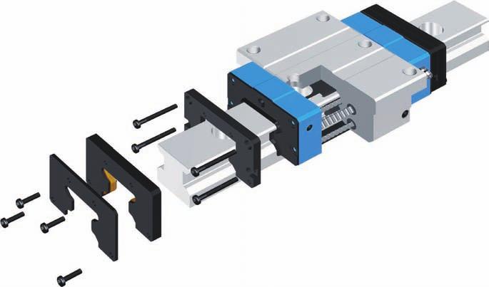
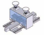
19 Mounting Track rail length q When assembling two or more sets of -Lube Linear Roller Way Super MX In case of an interchangeable product, assemble slide units and track rails with the same interchangeable code S2. on-interchangeable Use the assembly of slide unit(s and track rail as delivered without changing the combination. Matched sets to be used as an assembled group Special products of matched sets (by supplemental code /W are delivered as a group in which dimensional variations are specially controlled. Mount them without mixing with those of another group. w Assembling a slide unit and a track rail When assembling -Lube Linear Roller Way Super MX, correctly fit the groove of the slide unit mounted on a steel ball holder to the groove of the track rail, and then move the slide unit gently from the duy rail to the track rail in parallel direction. ylindrical rollers are retained, so the slide unit can be separated freely from the track rail. However, the slide unit can be assembled on the track rail much easier by using provided duy rail. Duy rail is appended as an accessory to the interchangeable slide unit. Duy rail is also appended to non-interchangeable product. Please use it when disassembling/assembling the slid unit. e Accuracy of mating mounting surfaces Depending on the accuracy of mating mounting surfaces and assembling accuracy, a load greater than the calculated load may act on -Lube Linear Roller Way Super MX. This will eventually give an adverse effect on the service life of -Lube Linear Roller Way Super MX. Therefore, the accuracy must be carefully examined. The accuracy of mating mounting surfaces for track rail and slide unit and the assembling accuracy must be determined considering the operating conditions, required running accuracy and rigidity, etc. Also, the mounting structure must be examined to ensure accuracy and performance for the reliable use of a linear motion rolling guide. When multiple sets are mounted, the parallelism between the two mounting surfaces of machines must be prepared. General guide line is shown in Table. These values are also applicable to right angled mounting and back to back mounting. Table Parallelism between two mounting surfaces unit : m Super Ultra High Precision lass precision precision H P SP UP Parallelism Track rail length Standard and maximum lengths of track rails are shown in Table 22.1 to 22.. Track rails in different lengths are available upon request. Simply indicate the necessary length of track rail in millimeter ( in the identification. In non-interchangeable, for track rails longer than the maximum length are shown in Table 22.1 to 22., butt-jointing r leaning the mounting surfaces When mounting -Lube Linear Roller Way Super MX, firstly clean all the mounting and reference mounting surfaces. (See Fig. Remove burrs and blemishes from the reference mounting surfaces and mounting surfaces of the machine using an oil-stone, etc., and then wipe the surfaces with clean cloth. Fig. leaning the mounting surfaces t Tightening torque values of mounting bolts The standard torque values for -Lube Linear Roller Way Super MX mounting bolts are shown in Table 21. When machines or equipment are subjected to serve vibration, shock, large fluctuating load or moment load, the bolts should be tightened with a torque 1.2 to 1. times higher than the standard torque values shown. When the mating member material is cast iron or aluminum, tightening torque should be lowered in accordance with the strength characteristics of the material. Table 21 Tightening torque of mounting bolts Tightening torque m Bolt size arbon steel bolt Stainless steel bolt Strength division.property division A2-0 M M0...0 M M M M 1. M M Remark : For tightening torque values for slide unit center mounting holes on size to 3 of flange type (MX, MX, MXG, MXL, 0% to 0% of the values in Table 21 are recoended. track rails are available upon request. In this case, indicate supplemental code /A in the identification. dimensions at both ends are the same unless otherwise specified. To change these dimensions, specify the specified rail mounting hole positions (supplemental code / of optional special. Table 22.1 Standard and maximum lengths of track rails (For high carbon steel Item Standard length Ln Mounting hole pitch F Reference Over (Incl. dimension 1 Under Maximum length 2 n (umber of mounting holes F ote 1 : ot applicable to the track rail with female threads for bellow mounting. (Supplemental code /J 2 : The track rails can be manufactured up to the maximum length shown in parentheses. If required, please consult Remark 1: The table shows representative model s and is also applicable to all models in the same size. 2: In case of half pitch (/HP, see Table Table 22.2 Standard and maximum length of track rails (For high carbon steel and half pitch /HP Item Standard length Ln Mounting hole pitch F Reference Over (Incl. dimension 1 Under Maximum length 2 ote 1 : ot applicable to the track rail with female threads for bellow mounting. (Supplemental code /J 2 : The track rails can be manufactured up to the maximum length shown in parentheses. If required, please consult for further information. Remark 1: The table shows representative model s and is also applicable to all models in the same size. 2: In case of half pitch (/HP, see Table 22.. L for further information. 1 = 0.2kgf = 0.22lbs. 1 = 0.033inch unit : MX MX MX 2 MX MX 3 MX MX MX unit : MX/HP MX/HP MX2/HP MX/HP MX3/HP MX/HP MX/HP MX/HP ote 1 : ot applicable to the track rail with female threads for bellow mounting. (Supplemental code /J 2 : The track rails can be manufactured up to the maximum length shown in parentheses. If required, please consult for further information. Remark : The table shows representative model s and is also applicable to all models in the same size. Table 22.3 Standard and maximum length of track rails Table 22. Standard and maximum length of track rails (For stainless steel unit : (For stainless steel and half pitch /HP unit : Item Standard length Ln Mounting hole pitch F Reference Over (Incl. dimension 1 Under Maximum length 2 MXDSL MXDSL MXD2SL MXDSL Item Standard length Ln Mounting hole pitch F Reference Over (Incl. dimension 1 Under Maximum length 2 MXDSL /HP MXDSL /HP MXD2SL /HP MXDSL /HP ote 1 : ot applicable to the track rail with female threads for bellow mounting. (Supplemental code /J 2 : The track rails can be manufactured up to the maximum length shown in parentheses. If required, please consult for further information. Remark : The table shows representative model s and is also applicable to all models in the same size. 3 3
20 -Lube Linear Roller Way Super MX Flange type, and bottom W W 2 d 1 Short MX StandardMX High rigidity long MXG xtra high rigidity longmxl -M 1 (L /2 /2 (L (L 3-M 1 -M 1 d H H h H 1 H 2 H H 3 W MXH MXH MXHG MXHL mounted from bottom only 1 MXL MXHL d 3 F MX MXH MXMXH MXGMXHG MX MX MXG MX 1 MX 1 MXG 1 MX0 1 MX 2 MX 2 MXG 2 MX MX MX MXG MXL Mass (Reference Slide unit kg Track rail kg/m Dimension of assembly Dimension of slide unit H H 1 W 2 W L 1 L ote 1 : MX, MX, MXG and MXL can be mounted from the top only. For mounting from the bottom, use MXH, MXH, MXHG and MXHL which have same dimensions as above model. 2 : Track rail length L are shown in Table 22.1 and 22.2 on page 3. 3 : Track rail mounting bolts are not appended. Hexagon socket bolts of JIS B 11 strength division. or equivalent are recoended. : The directions of basic dynamic load rating (, basic static load rating ( 0 and static moment rating (T 0, and are shown in the sketches below. The upper values in the and column apply to one slide unit, and the lower values apply to two units in close contact. Remark 1 : The mark indicates that interchangeable products are available. 2: For grease nipple, see Table 1 on page 33. 3: A grease nipple mounting threaded hole is provided on each end plate respectively Dimension of track rail d 1 M 1 H 2 H 3 H W H d 3 d h F. 1 1 M. M M M Recoended 3 Basic Basic mounting dynamic static bolt for track rail load rating load rating Bolt size length xample of identification for assembled set MX 0 G M1 M M2 M R T1 T 0 m code Size Part code Preload symbol lass symbol P Static moment rating m code S2 m /F MX MX MXG MX 1 MX 1 MXG 1 MX0 1 MX 2 MX 2 MXG 2 MX MX MX MXG MXL Supplemental code.2kgf, 0 T 0 MX o symbol G L Series Flange type, mounting from top and bottom Length of slide unit Short Standard High rigidity long xtra high rigidity long Size,, 2, umber of slide unit (two units Preload amount o symbol Standard T1 Light preload T2 Medium preload T3 Heavy preload Length of track rail ( Accuracy class H High P Precision SP Super precision UP Ultra precision Special A, D,, F, G, HP, 1, J, L, LF, MA, M,, R, T, UR, V, W, Z code S2 on interchangeable o symbol 1 = 0.2kgf = 0.22lbs. 1 = 0.033inch 3 3
21 -Lube Linear Roller Way Super MX Flange type, and bottom Short MX Standard MX High rigidity long MXG xtra high rigidity longmxl W d 1 H W 2 (L /2 /2 d (L (L -M 1 3-M 1 -M 1 H 1 H H h H 2 H 3 W MXL d 3 MX MX MXG F L 1 MX 3 MX 3 MXG 3 MX MX MX MXG MXL MX MX MXG MXL MX MX MXG MXL Mass (Reference Slide unit kg Track rail kg/m Dimension of assembly Dimension of slide unit H H 1 W 2 W L 1 L d 1 M 1 H 2 H 3 H W H d 3 d h F ote 1 : Track rail length L are shown in Table 22.1 and 22.2 on page 3. 2 : Track rail mounting bolts are not appended. Hexagon socket bolts of JIS B 11 strength division. or equivalent are recoended. 3 : The directions of basic dynamic load rating (, basic static load rating ( 0 and static moment rating (T 0, and are shown in the sketches below. The upper values in the and column apply to one slide unit, and the lower values apply to two units in close contact. Remark 1 : The mark indicates that interchangeable products are available. 2: For grease nipple, see Table 1 on page 33. 3: Three female threaded holes for grease nipple are prepared on each end plate M M M1 M Dimension of track rail xample of identification for assembled set code Size Part code Preload symbol lass symbol MX G Recoended 2 Basic Basic mounting dynamic static bolt for track rail load rating load rating Bolt size length M 3 M M M R T1 T 0 Static moment rating 3 m P m m code S2 MX 3 MX 3 MXG 3 MX MX MX MXG MXL MX MX MXG MXL MX MX MXG MXL.2kgf Supplemental code /F, 0 T 0 MX o symbol G L Series Flange type, mounting from top and bottom Length of slide unit Short Standard High rigidity long xtra high rigidity long Size 3,,, Preload amount o symbol Standard T1 Light preload T2 Medium preload T3 Heavy preload Accuracy class H High P Precision SP Super precision UP Ultra precision Special A, D,, F, G, HP, 1, J, L, LF, MA, M,, R, T, UR, V, W, Z code S2 on interchangeable o symbol umber of slide unit (two units Length of track rail (00 1 = 0.2kgf = 0.22lbs. 1 = 0.033inch 3
22 -Lube Linear Roller Way Super MX Block type, (L (L (L Short MXD Standard MXD High rigidity long MXDG xtra high rigidity longmxdl Standard (Stainless steelmxdsl W 2 W M 1 depth H 3 /2 /2 3M 1 depth d M 1 H H H 1 h W MXDL d 3 MXD MXD MXDG F L 1 MXD MXD MXD SL MXDG MXD MXD MXD SL MXDG MXD0 MXD 2 MXD MXD 2 2SL MXDG 2 MXD MXD MXD MXD SL MXDG MXDL Mass (Reference Slide unit kg Track rail kg/m Dimension of assembly H H 1 W 2 W L 1 L M 1 depth H 3 W H d 3 d h F ote 1 : Track rail length L are shown in Table , 22.3 and 22. on page 3. 2 : Track rail mounting bolts are not appended. Hexagon socket bolts of JIS B 11 strength division. or equivalent are recoended. 3 : The directions of basic dynamic load rating (, basic static load rating ( 0 and static moment rating (T 0, and are shown in the sketches below. The upper values in the and column apply to one slide unit, and the lower values apply to two units in close contact. Remark 1 : The mark indicates that interchangeable products are available. 2: For grease nipple, see Table 1 on page 33. 3: A grease nipple mounting threaded hole is provided on each end plate respectively Dimension of slide unit M M M M Dimension of track rail xample of identification for assembled set 0 code Recoended 2 Basic Basic mounting dynamic static bolt for track rail load rating load rating Bolt size length M1 M M2 M2 Size Part code Material symbol Preload symbol lass symbol MXD G 2 2 R T1 P T 0 m Static moment rating 3 m code S2 m MXD MXD MXD SL MXDG MXD MXD MXD SL MXDG MXD0 MXD 2 MXD 2 MXD 2SL MXDG 2 MXD MXD MXD MXD SL MXDG MXDL.2kgf Supplemental code /F, 0 T 0 MXD o symbol G L Series Block type, Length of slide unit Short Standard High rigidity long xtra high rigidity long umber of slide unit (two units Length of track rail ( Size,, 2, Preload amount o symbol Standard T1 Light preload T2 Medium preload T3 Heavy preload Material code o symbol High carbon steel SL Stainless steel Accuracy class H High P Precision SP Super precision UP Ultra precision Special A, D,, F, G, HP, 1, J, L, LF, MA, M,, R, T, UR, V, W, Z code S2 on interchangeable o symbol 1 = 0.2kgf = 0.22lbs. 1 = 0.033inch 1 2
23 -Lube Linear Roller Way Super MX Block type, Short MXD Standard MXD High rigidity long MXDG xtra high rigidity longmxdl W 2 W (W 1 (L M 1 depth /2 /2 3M 1 depth d (L (L M 1 depth H H 1 h H H 3 W MXDL d 3 MXD MXD MXDG F L 1 MXD 3 MXD 3 MXDG 3 MXD MXD MXD MXDG MXDL MXD MXD MXDG MXDL MXD MXD MXDG MXDL Mass (Reference Slide unit kg Track rail kg/m Dimension of assembly H H 1 W 1 W 2 W L 1 L M 1 depth H 3 W H d 3 d h F ote 1 : Track rail length L are shown in Table 22.1 and 22.2 on page 3. 2 : Track rail mounting bolts are not appended. Hexagon socket bolts of JIS B 11 strength division. or equivalent are recoended. 3 : The directions of basic dynamic load rating (, basic static load rating ( 0 and static moment rating (T 0, and are shown in the sketches below. The upper values in the and column apply to one slide unit, and the lower values apply to two units in close contact. Remark 1 : The mark indicates that interchangeable products are available. 2: For grease nipple, see Table 1 on page 33. 3: Three female threaded holes for grease nipple are prepared on each end plate Dimension of slide unit M1 M M2 M Dimension of track rail Recoended 2 Basic Basic mounting dynamic static bolt for track rail load rating load rating M3 M M M1 xample of identification for assembled set Bolt size length code Size Part code Preload symbol lass symbol MXD G 2 R00 T1 P T 0 m Static moment rating 3 m code S2 m MXD 3 MXD 3 MXDG 3 MXD MXD MXD MXDG MXDL MXD MXD MXDG MXDL MXD MXD MXDG MXDL.2kgf Supplemental code /F, 0 T 0 MXD o symbol G L Series Block type, Length of slide unit Short Standard High rigidity long xtra high rigidity long Size 3,,, Preload amount o symbol Standard T1 Light preload T2 Medium preload T3 Heavy preload Accuracy class H High P Precision SP Super precision UP Ultra precision Special A, D,, F, G, HP, 1, J, L, LF, MA, M,, R, T, UR, V, W, Z code S2 on interchangeable o symbol umber of slide unit (two units Length of track rail (00 1 = 0.2kgf = 0.22lbs. 1 = 0.033inch 3
24 -Lube Linear Roller Way Super MX ompact block type, Short MXS Standard MXS High rigidity long MXSG xtra high rigidity longmxsl W 2 W H 3 M 1 (L /2 /2 3M 1 d (L (L M 1 H H 1 H h W MXSL d 3 MXS MXS MXSG F L 1 MXS MXS MXSG MXS MXS MXSG MXS0 MXS 2 MXS 2 MXSG 2 MXS MXS MXS MXSG MXSL Mass (Reference Slide unit kg Track rail kg/m Dimension of assembly H H 1 W 2 W L 1 L M 1 depth 2 H 3 W H d 3 d h F ote 1 : Track rail length L are shown in Table 22.1 and 22.2 on page 3. 2 : Recoended screwing depth are shown in Table 1.1 on page : Track rail mounting bolts are not appended. Hexagon socket bolts of JIS B 11 strength division. or equivalent are recoended. : The directions of basic dynamic load rating (, basic static load rating ( 0 and static moment rating (T 0, and are shown in the sketches below. The upper values in the and column apply to one slide unit, and the lower values apply to two units in close contact. Remark 1 : The mark indicates that interchangeable products are available. 2: For grease nipple, see Table 1 on page 33. 3: A grease nipple mounting threaded hole is provided on each end plate respectively Dimension of slide unit M. M. M M Dimension of track rail Recoended 3 Basic Basic mounting dynamic static bolt for track rail load rating load rating xample of identification for assembled set 0 Bolt size length M1 M M2 M2 code Size Part code Preload symbol lass symbol MXS G 2 2 R T1 P T 0 m Static moment rating m code S2 m MXS MXS MXSG MXS MXS MXSG MXS0 MXS 2 MXS 2 MXSG 2 MXS MXS MXS MXSG MXSL.2kgf Supplemental code /F, 0 T 0 MXS o symbol G L Series ompact block type, Length of slide unit Short Standard High rigidity long xtra high rigidity long Size,, 2, Preload amount o symbol Standard T1 Light preload T2 Medium preload T3 Heavy preload Accuracy class H High P Precision SP Super precision UP Ultra precision Special A, D,, F, G, HP, 1, J, L, LF, MA, M,, R, T, UR, V, W, Z code S2 on interchangeable o symbol umber of slide unit (two units Length of track rail ( 1 = 0.2kgf = 0.22lbs. 1 = 0.033inch
25 Low section flange type, -Lube Linear Roller Way Super MX Standard MX High rigidity long MXG xtra high rigidity longmxl W W 2 d 1 (L (L M 1 L M 1 /2 /2 d H H 1 H 2 W H 3 H h d 3 MX MXG MXL MX MXG F L 1 MX 3 MXG 3 MX MX MXG MXL MX MXG MXL Mass (Reference Slide unit kg Track rail kg/m Dimension of Dimension of slide unit Dimension of track rail assembly 3 Maximum H H W 2 W L 1 L L d M 1 screwing H 2 H 3 W H d 3 d h F depth ote 1 : Track rail length L are shown in Table 22.1 and 22.2 on page 3. 2 : It is recoended to secure actual screwing depth should not exceed the maximum screwing depth in the table. 3 : Track rail mounting bolts are not appended. Hexagon socket bolts of JIS B 11 strength division. or equivalent are recoended. : The directions of basic dynamic load rating (, basic static load rating ( 0 and static moment rating (T 0, and are shown in the sketches below. The upper values in the and column apply to one slide unit, and the lower values apply to two units in close contact. Remark 1 : The mark indicates that interchangeable products are available. 2: For grease nipple, see Table 1 on page 33. 3: In size 3 female threads for grease nipple are prepared on both side faces and front face of end plate. Thread size of front face is smaller than other threads thus, please consult if grease nipple for front face is required M M M Recoended mounting bolt for track rail Basic dynamic load rating Basic static load rating Bolt size length M 3 M M T 0 m Static moment rating m m MX 3 MXG 3 MX MX MXG MXL MX MXG MXL.2kgf xample of identification for assembled set code Size Part code Preload symbol lass symbol MX G 2 R00 T2 P code S2 Supplemental code /F MX Series Low section flange type, Special A, D,, F, HP, 1, J, L, LF, MA, R, T, UR, V, W, Z 0 T 0 o symbol G L Length of slide unit Standard High rigidity long xtra high rigidity long Size 3,, Preload amount o symbol Standard T1 Light preload T2 Medium preload T3 Heavy preload Accuracy class H High P Precision SP Super precision UP Ultra precision code S2 on interchangeable o symbol umber of slide unit (two units Length of track rail (00 1 = 0.2kgf = 0.22lbs. 1 = 0.033inch
26 Low section block type, -Lube Linear Roller Way Super MX Standard MXS High rigidity long MXSG xtra high rigidity longmxsl (W 1 W 2 W M 1 depth (L (L /2 /2 M 1 depth d H H h H 3 H 1 W d 3 MXS MXSG MXSL F L 1 MXS 3 MXSG 3 MXS MXS MXSG MXSL MXS MXSG MXSL Mass (Reference Slide unit kg Track rail kg/m Dimension of assembly H H 1 W 1 W 2 W L 1 L Dimension of slide unit 2 Maximum M 1 depth 2 screwing depth ote 1 : Track rail length L are shown in Table 22.1 and 22.2 on page 3. 2 : It is recoended to secure actual screw depth should not be exceed the maximum screwing depth in table 1.2 on page 32. specially the screwing depth of middle mounting threads in width direction should not be exceed maximum screwing depth in the table. 3 : Track rail mounting bolts are not appended. Hexagon socket bolts of JIS B 11 strength division. or equivalent are recoended. : The directions of basic dynamic load rating (, basic static load rating ( 0 and static moment rating (T 0, and are shown in the sketches below. The upper values in the and column apply to one slide unit, and the lower values apply to two units in close contact. Remark 1 : The mark indicates that interchangeable products are available. 2: For grease nipple, see Table 1 on page 33. 3: In size 3 female threads for grease nipple are prepared on both side faces and front face of end plate. Thread size of front face is smaller than other threads thus, please consult if grease nipple for front face is required M M11 M H Dimension of track rail W H d 3 d h F Recoended 3 mounting bolt for track rail Basic dynamic load rating Basic static load rating Bolt size length M 3 M M T 0 m Static moment rating m m MXS 3 MXSG 3 MXS MXS MXSG MXSL MXS MXSG MXSL.2kgf xample of identification for assembled set code Size Part code Preload symbol lass symbol MXS G 2 R00 T2 P code S2 Supplemental code /F MXS Series Low section block type, Special A, D,, F, HP, 1, J, L, LF, MA, R, T, UR, V, W, Z 0 T 0 o symbol G L Length of slide unit Standard High rigidity long xtra high rigidity long Size 3,, Preload amount o symbol Standard T1 Light preload T2 Medium preload T3 Heavy preload Accuracy class H High P Precision SP Super precision UP Ultra precision code S2 on interchangeable o symbol umber of slide unit (two units Length of track rail (00 1 = 0.2kgf = 0.22lbs. 1 = 0.033inch 0

27

28
Identification Number
 Identification Number The specification of Micro Linear Way LWL is specified by the identification number, which consists of a model code, a size, a part code, a preload symbol, a classification symbol,
 Identification The specification of C-Lube Linear ay is identified by the identification, which consists of a model code, a size, a part code, a material code, a preload symbol, a classification symbol,
C-Lube Linear Way ML Linear Way L ML LWL
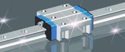
 -Lube Linear ay ML Linear ay L MLLL -Lube Maintenance ree Series -Lube Linear ay ML ML long term maintenance free supported! The aquamarine end plate is the symbol of maintenance free. Identification umber
C-Lube Linear Way ML ML MLF
 Maintenance ree & U.S. PTTD C-Lube Linear ay Variation of C-Lube Linear ay Shape Length of slide unit Model code C-Lube Linear ay is a linear motion rolling guide, incorporating the C-Lube as a components
Maintenance Free C-Sleeve Linear Way ML ME MH MUL
 Maintenance ree C-Sleeve Linear ay M M MUL CAT-A e aim to be a Technology-Developing company taking customer-need as primary source for the development. ith our original technologies and creativities,
Maintenance Free C-Sleeve Linear Way
 U.S. PATTD Maintenance ree C-Sleeve Linear ay M M MUL Maintenance free for,000 km or or years CAT- Printed in Japan 0.0 (SIG Maintenance ree & C-Sleeve Linear ay strives to be a leader in Technology. Our
General Explanation Ⅲ 1 Ⅲ 2
 General Explanation 1 2 Selection Procedure Selection of Linear Way and Linear Roller Way should be considered from the most important required matter to details in order. Typical procedure is shown below.
Slide unit. Casing. Model. 3 Size. Linear Way E LWE. 6 Material type. 9 Interchangeable
 -Lube Maintenance ree Series -Lube Linear Way M M period maintenance free supported! Te aquamarine end plate is te symbol of maintenance free. Identification umber and Specification xample of an identification
SLIDE GUIDE SGL TYPE SLIDE GUIDE BLOCK TYPES ACCURACY
 SGL YPE he N slide is a linear motion earing utilizing the rotational motion of all elements along four rows of raceway grooves. It can e used in various applications due to its compactness and high load
Low Decibel Linear Way E
 U.S. PATNTD Low Decibel Linear Way LWQLWTQLWSQ Low Decibel Linear Way series Sape lange type mounted from bottom Low Decibel Linear Way is a linear motion rolling guide for smoot and quiet motion. Its
Precision Ball Screw/Spline
 58-2E Models BNS-A, BNS, NS-A and NS Seal Outer ring Shim plate Seal Spline nut Seal Collar Shim plate Seal End cap Ball Outer ring Ball screw nut Outer ring Ball Retainer Retainer Outer ring Point of
SLIDE GUIDE SGL TYPE SLIDE GUIDE BLOCK TYPES ACCURACY
 SGL YPE he N slide is a linear motion earing utilizing the rotational motion of all elements along four rows of raceway grooves. It can e used in various applications due to its compactness and high load
Miniature (SEB Type) Tapped-Hole rail Types: Slide guides with clearance holes are standard and tapped holes are available upon request.
 Tapped-Hole rail Types: Slide guides with clearance holes are standard and tapped holes are available upon request.") Miniature (SE Type) The SE type slide guide is a linear motion bearing in which the ball elements roll along two tracking grooves. This is the smallest and lightest slide guide series offered by Nippon
Miniature (SE Type) The SE type slide guide is a linear motion bearing in which the ball elements roll along two tracking grooves. This is the smallest and lightest slide guide series offered by Nippon
Points. Precision Positioning Table TU. Variation. Major product specifications With flange
 9 0 Precision Positioning Table Ball screw inear Points lide table with high accuracy and high rigidity in a single structure lide table Compact and slim type positioning table with an original U-shaped
The basic dynamic load rating C is a statistical number and it is based on 90% of the bearings surviving 50 km of travel carrying the full load.
 Technical data Load Rating & Life Under normal conditions, the linear rail system can be damaged by metal fatigue as the result of repeated stress. The repeated stress causes flaking of the raceways and
Miniature Slide Guide Series with Retained Ball now Offers Complete Selection
 Miniature Slide Guide Series with Retained Ball now Offers Complete Selection Wide type of Miniature Slide Guide, providing greater allowable moment, is now available with retained ball structure. Due
Cam Roller Guides. The Drive and Control Company. Service Automation. Electric Drives and Controls. Linear Motion and Assembly Technologies
 Industrial Hydraulics Electric Drives and Controls Linear Motion and Assembly Technologies Pneumatics Service Automation Mobile Hydraulics Cam Roller Guides The Drive and Control Company Linear Motion
Ball screw. Linear. Coupling cover. 1Positioning table of a structure with enhanced sealing property. 3 High corrosion resistance
 Cleanroom Precision Positioning Table TC Ball screw TC EB Slide table inear Way Side cover Stainless sheet Motor bracket inear Coupling cover Pipe threads for suction connector Points ight weight, low
R-Plus System Frontespizio_R_PlusSystem.indd 1 11/06/ :32:02
 R-Plus System R-Plus System R-Plus system R-Plus system description Fig. R-Plus system R-Plus System is Rollon s series of rack & pinion driven actuators. Rollon R-Plus System series linear units are designed
The SynchMotion. Retainer
 106 G99TE13-0809 Linear Guideways QE Series 2-9 QE Type Quiet Linear Guideway, with SynchMotion TM Technology The development of HIIN-QE linear guideway is based on a four-row circular-arc contact. The
Drive Units with Ball Screw Drives R310EN 3304 ( ) The Drive & Control Company
 The Drive & Control Company") Drive Units with Ball Screw Drives R310EN 3304 (2007.05) The Drive & Control Company Linear Motion and Assembly Technologies Ball Rail Systems Roller Rail Systems Linear Bushings and Shafts Precision Ball
Drive Units with Ball Screw Drives R310EN 3304 (2007.05) The Drive & Control Company Linear Motion and Assembly Technologies Ball Rail Systems Roller Rail Systems Linear Bushings and Shafts Precision Ball
FOUR-POINT CONTACT SLEWING RINGS - without gear [ O ]
![FOUR-POINT CONTACT SLEWING RINGS - without gear [ O ]](/thumbs/96/126795264.jpg "FOUR-POINT CONTACT SLEWING RINGS - without gear [ O ]") FOUR-POINT CONTACT SLEWING RINGS - without gear [ O ] Number of the Loading Boundary Dimensions Static Ax.Basic Load Rating Designation Weight Abutment Dimensions Curve d D T C oa G J 1 J 2 N 1 N 2 n 1
FOUR-POINT CONTACT SLEWING RINGS - without gear [ O ] Number of the Loading Boundary Dimensions Static Ax.Basic Load Rating Designation Weight Abutment Dimensions Curve d D T C oa G J 1 J 2 N 1 N 2 n 1
PROCESS FOR SELECTING NB LINEAR SYSTEM
 The NB linear system is a linear motion mechanism which utilizes the recirculating movement of ball or roller elements to provide smooth and accurate linear travel. NB offers a wide range of linear motion
ER2 Short-head Electric Chain Hoist
 O/M NO.SHER2-0903-CE-00 ER2 Short-head Electric Chain Hoist (250kg to 5t) Operation Manual (SHER2M/SHER2SG/SHER2SP) Introduction The KITO Short-head Electric Chain Hoist is intended for effective use in
BEARINGS Pillow Blocks
 The bearing size is usually selected according to the required bearing life and reliability under a specified type of load charged on the bearing. The load applied to the bearing operating under a static
SNL plummer block housings, 2, 3, 5 and 6 series Other bearing housings Large SNL plummer block housings
 Bearing housings SNL plummer block housings, 2, 3, 5 and 6 series... 1033 Other bearing housings... 1058 Large SNL plummer block housings... 1058 SONL plummer block housings... 1059 SDG plummer block housings...
Linear Guides SH Series
 inear Guides S Series Ball Slide Models: A, B Front view of A and B types Side view of B type MRO B1 W B 4-M l 1 T MYO K E B 3 W2 W1 Model o. SA SB SA SB S2A S2B SA SB S3A S3B S4A S4B SA SB Assembly Ball
1 High precision, high rigidity positioning table
 TSHM CTHM 11 116 Precision Positioning Table H Ball screw TSH M Ball screw Slide table inear Way Bed inear Points 1 High precision, high rigidity positioning table High precision, high rigidity positioning
Series MHY2/MHW Angular Gripper. Cam actuation style is now standardized! MHZ2 MHZJ2 MHQ MHL2 MHR MHK MHS MHC2 MHT2 MHY2 MHW2 MRHQ 2.
 18 Angular Gripper Cam Style Rack & Pinion Style Series / Cam actuation style is now standardized! 2.8-1 18 Angular Gripper 18 Angular Gripper Series / Cam Style Rack & Pinion Style Series / Series MHY/Cam
Linear guide drives. Synchronous shafts The use of synchronous shafts enables several linear axes to be operated with one drive.
 Linear guide drives Drive concept The linear guides are driven via the hollow shaft in the drive head. The drive head is used to directly install a motor or alternatively (in connection with a center shaft)
Product Description. Further highlights. Outstanding features. 4 Bosch Rexroth Corporation Miniature Linear Modules R310A 2418 (2009.
 4 Bosch Rexroth orporation Miniature Linear Modules R310A 2418 (2009.05) Product Description Outstanding features Rexroth Miniature Linear Modules are precise, ready-to-install linear motion systems that
Bettis RGS F-Series. Quarter-Turn Spring-Return (SR) and Double-Acting (DA) Pneumatic Actuators. Product Data Sheet RGS Rev.
 and Double-Acting (DA) Pneumatic Actuators. Product Data Sheet RGS Rev.") Bettis RGS F-Series Quarter-Turn Spring-Return (SR) and Double-Acting (DA) Pneumatic Actuators Output Torques to 500,000 in-lb (56,492 N m) Ductile Iron or Stainless-Steel Construction Temperatures from
Bettis RGS F-Series Quarter-Turn Spring-Return (SR) and Double-Acting (DA) Pneumatic Actuators Output Torques to 500,000 in-lb (56,492 N m) Ductile Iron or Stainless-Steel Construction Temperatures from
Type Plunger Height x pitch Operating force (OF) Without ground terminal Flat type 4.3 x 6.5 mm General 0.98 N (100 gf) B3F-6000 B3F-6100
 Without ground terminal Flat type 4.3 x 6.5 mm General 0.98 N (100 gf) B3F-6000 B3F-6100") Mechanical Key Switch (Ral) B3F- Taped Ral Switches Automatic mounting possible via general- ral taped component inserters. Conform to EIAJ RC 1008A Electronic Component Taping Dimensions. The same snap-action
Mechanical Key Switch (Ral) B3F- Taped Ral Switches Automatic mounting possible via general- ral taped component inserters. Conform to EIAJ RC 1008A Electronic Component Taping Dimensions. The same snap-action
Product description. Compact Modules. Characteristic features. Further highlights
 4 Compact Modules Product description Characteristic features Five fine-tuned sizes based on a compact precision aluminum profile with two integrated pre-tensioned ball rail systems Identical external
General Explanation Ⅲ 1 Ⅲ 2
 General Explanation 1 2 Load Rating and Life Life of linear motion rolling guides Even in normal operational status, a linear motion rolling guide will reach the end of its life after a certain period
CTV series CHARACTERISTICS LINEAR UNITS
 CTV series CHARACTERISTICS The CTV series describes s with a precision ball screw drive and two parallel, integrated, Zerobacklash rail guides. Compact dimensions allow high performance features such as,
Load Washers. Force. for Forces of 7, kn. F z. Type 9001A A 9081B, 9091B
 Force Load Washers for Forces of 7,5... 1 200 kn Type 9001A... 9071A 9081B, 9091B 1-component force sensor for measuring dynamic and quasistatic forces in z direction. F z Calibrated measuring range 100
second PLSA line R310EN 3308 ( )
") 01_1 Planetary st Headline_36 Screw Assemblies pt/14.4 mm second PLSA line R310EN 3308 (2011-09) 2 Planetary Screw Assemblies PLSA Planetary Screw Assemblies PLSA Product Overview 3 Nuts, Screws, Screw
01_1 Planetary st Headline_36 Screw Assemblies pt/14.4 mm second PLSA line R310EN 3308 (2011-09) 2 Planetary Screw Assemblies PLSA Planetary Screw Assemblies PLSA Product Overview 3 Nuts, Screws, Screw
STAF Linear Guide. STAF Linear Guide Integrated Rail for Non Cage Type and Cage Type.
 STAF Linear Guide STAF Linear Guide Integrated Rail for Non Cage Type and Cage Type www.staf.com.tw A. Terms of Linear Guide 1-1 Main Factors a. Lifetime and Load of Linear Guide Selection of linear guide
Identification system for short product names. Changes/amendments at a glance. 2 Bosch Rexroth AG OBB omega modules R ( )
") Omega Modules OBB 2 OBB omega modules R9990079 (206-05) Identification system for short product names Short product name Example: O B B - 085 - N N - System = Omega module Guideway = Ball Rail System Drive
Omega Modules OBB 2 OBB omega modules R9990079 (206-05) Identification system for short product names Short product name Example: O B B - 085 - N N - System = Omega module Guideway = Ball Rail System Drive
ENGINEERING INFORMATION TABLE OF CONTENTS SHAFT AND HOUSING FITS LUBRICATION LIFE AND LOAD RATINGS RADIAL CLEARANCE CHART
 ENGINEERING INFORMATION TABLE OF CONTENTS ENGINEERING INFORMATION SHAFT AND HOUSING FITS LUBRICATION LIFE AND LOAD RATINGS RADIAL CLEARANCE CHART SHAFT AND HOUSING FITS FOR METRIC RADIAL BALL AND ROLLER
Low Profile Slide Table
 Low Profile Slide Table Series ø, ø, ø1, ø Low-profile and compact type, air slide table with the construction of guide and cylinder aligned in parallel. Neat appearance Protecting stopper section with
Planetary Screw Assemblies PLSA
 Planetary Screw Assemblies PLSA R310EN 3308 (2011-09) The Drive & Control Company C/ Centauro, 13 Área Empresarial Las Cubiertas 28971-Griñón (Madrid) T. 0034 91 126 6627 info@diversiatec.com www.diversiatec.com
Monoca rrier TM CBLOCK C1-C22 C23-C68 C69-C88
 C-1 TM 1. Features C1 2. Classifications and Series C. Optional Components C. Selection of.1. Procedures for Selecting C.2. Rigidity C.. Maximum Speed C.. Accuracy Grade C.. Stroke and Ball Screw Lead
LINE TECH Linear Modules. Ready to built-in linear modules with drive
 Ready to built-in linear modules with drive Anodized profile, produced in extrusion molding method Linear rail guiding system (LM3 LM5) Actuation by ball screw, high-helix lead _ screw or toothed belt
MonocarrierTM Monocarrier
 Monocarrier TM Significantly saves designing load of machinery through an integration of linear motion components in one unit. Demonstrates high performance in a wide range of applications, including assembling
Connector~Tech Providing Harsh Environment Connector
 Connector~Tech www.connectortech.com.au Providing Harsh Environment Connector SOLUTIONS Tajimi TC18 series connectors are water-pro up to 30 meters in depth. Economical and highly reliable construction
Planetary Screw Assemblies PLSA
 Planetary Screw Assemblies PLSA Ernst-Sachs-Straße 100 97424 Schweinfurt Tel. +49 9721 937-0 Fax +49 9721 937-275 www.boschrexroth.com Catalog "Planetary Screw Assemblies PLSA" R310XX 3308 (2014.01) Dear
G-FIRE FLANGE ADAPTERS
 G-FIRE FLANGE ADAPTERS 21 G-FIRE FLANGE ADAPTERS Pictorial Table of Contents MATERIAL SPECIFICATIONS Issue 03, 04, 07 Cert No. 570, 669, 673 For detailed Listing and Approval information see pages 101-10
Must Read Before Installation TadPoleTM Safety and Warnings
 Must Read Before Installation TadPoleTM Safety and Warnings The recommendations, requirements, rules, and instructions of your Vehicle's Roof-Top Rack System should ALWAYS be followed. The TadPole TM,
ADVANCED MOTION TECHNOLOGIES CORP.
 LINEAR GUIDEWAY ADVANCED MOTION TECHNOLOGIES COR. No.7, Lane 89, Chung Shan Rd., Shen Kang Hsiang, Taichung Hsien 49, Taiwan TEL: +886464 FAX: +8864686 Email: amt.info@pmiamt.com.tw Web site: www.pmiamt.com
Electron Microscopy Sciences INSTRUCTION MANUAL. Stereo Microscopes Non-illuminated Stands
 Electron Microscopy Sciences 1 INSTRUCTION MANUAL Stereo Microscopes Non-illuminated Stands Model GL7-207: Binocular, 6.5:1 Zoom Ratio 10X to 65X, smooth ball bearing construction and Model GL7-307: Trinocular,
Identification Number. Accuracy. Clearances. Examples of identification number. Table 3 Radial internal clearance. Table 1 Tolerances
 Identiication umber Accuracy learances The identiication number example o Hex Head am Followers are shown below. Examples o identiication number Tolerances o Hex Head am Followers are shown in Table and
SOLUTION (17.3) Known: A simply supported steel shaft is connected to an electric motor with a flexible coupling.
 Known: A simply supported steel shaft is connected to an electric motor with a flexible coupling.") SOLUTION (17.3) Known: A simply supported steel shaft is connected to an electric motor with a flexible coupling. Find: Determine the value of the critical speed of rotation for the shaft. Schematic and
SOLUTION (17.3) Known: A simply supported steel shaft is connected to an electric motor with a flexible coupling. Find: Determine the value of the critical speed of rotation for the shaft. Schematic and
Crossed Roller Bearings
 Special Selection & http://www.ikont.eu Official Distributer in Unite Kingom rosse Bearings Unit rackley Way Peartree Lane Duley, West Milans DY UW Tel : 9 / E-mail : uley@goiva-bearings.co.uk for AT-EG
Formulae and examples of calculation
 Shock absorber Formulae and examples of calculation A shock absorber decelerates linearly. Roughly 90% of shock absorber applications can be modelled if the following 4 factors are known: 1. Mass to slow
SMD Switch SI-C3436A General specification. Soldering conditions Reflow Soldering condition. Standard Reel Dimensions (mm) Packing specification
 Packing specification") SMD Switch SI - C3436A - 7017 Features External Dimensions : 3.4mm x 3.6mm, Height 0.70mm Suitable for thinner and lighter portable devices Suitable for water proof devices Reflow soldering Package With
SMD Switch SI - C3436A - 7017 Features External Dimensions : 3.4mm x 3.6mm, Height 0.70mm Suitable for thinner and lighter portable devices Suitable for water proof devices Reflow soldering Package With
Standard Range Nominal Diameter 3-16 mm
 Standard Range Nominal Diameter - 1 mm 2 steps for ordering properly: Choose screw type A or B for ground or rolled screws: 1412 or 142 Flange 2422 or 2442 End cap with flange 1214 or 124 Cylindrical 1112
PLOW MOUNT KIT FOR POLARIS RANGER P/N ASSEMBLY / OWNERS MANUAL
 PLOW MOUNT KIT FOR POLARIS RANGER P/N 34-3010 ASSEMBLY / OWNERS MANUAL Application PLOW PUSH FRAME NO. 34-0000 or 34-0070 Before you begin, please read these instructions and check to be sure all parts
Front flange FLV. Max. [knm/stroke]
![Front flange FLV. Max. [knm/stroke]](/thumbs/92/109382839.jpg "Front flange FLV. Max. [knm/stroke]") SDN 45 Safety shock absorbers SDN are a low cost alternative to industrial shock absorbers appropriate to customers requirements. Typical applications: cranes, storage and retrieval unit for highbay warehouse,
SDN 45 Safety shock absorbers SDN are a low cost alternative to industrial shock absorbers appropriate to customers requirements. Typical applications: cranes, storage and retrieval unit for highbay warehouse,
AME Model. (1) Rated flow (l/min (ANR)) Port size (Nominal size B) Weight (kg)
 Rated flow (l/min (ANR)) Port size (Nominal size B) Weight (kg)") Super Mist Separator Series AME Series AME separates and absorbs aerosol state fine oil particles in compressed air and changes the oil lubricating compressed air to oilless equivalent air. It should be
Super Mist Separator Series AME Series AME separates and absorbs aerosol state fine oil particles in compressed air and changes the oil lubricating compressed air to oilless equivalent air. It should be
Chapter 11. Bearing Types. Bearing Load. The Reliability Goal. Selection of Tapered Roller Bearings
 Chapter 11 Rolling Contact Bearing Bearing Types Bearing Life Bearing Load Bearing Survival The Reliability Goal Selection of Ball and Straight Roller Bearings Selection of Tapered Roller Bearings 1 Introduction
180 Angular Gripper. Series MHY2/MHW2. Cam actuation style is now standardised! 5-241
 18 Angular Gripper Cam tyle Rack & Pinion tyle eries MHY2/MHW2 Cam actuation style is now standardised! -21 18 Angular Gripper Cam tyle Rack & Pinion tyle eries MHY2/MHW2 eries MHY/Cam tyle Light and compact
Modular Style Air Combination. Assembled by simply tightening the screws
 Modular Style Air Combination Series AC Assembled by simply tightening the screws High strength die cast bracket Drain cock for one push drain exhaust Oil needle for easy oil volume adjustments The improved
UNI EN ISO 9001:2008 UNI EN ISO 14001:2004 BS OHSAS 18001:2007 EC DIRECTIVE 2014/34/EU (ATEX) CERTIFIED MANAGEMENT SYSTEM
 CERTIFIED MANAGEMENT SYSTEM") EN ISM-BSM CERTIFIED Technology Made in Italy Since 1955 the Varvel Group has been making speed reducers and variators for light industry applications. Reliable partner in power transmission equipment
EN ISM-BSM CERTIFIED Technology Made in Italy Since 1955 the Varvel Group has been making speed reducers and variators for light industry applications. Reliable partner in power transmission equipment
INSTALLATION INSTRUCTIONS ATV Plow Blade Part Number: (50 ), (54 ), or (60 ) Application: All Terrain Vehicles
, (54 ), or (60 ) Application: All Terrain Vehicles") INSTALLATION INSTRUCTIONS ATV Plow Blade Part Number: 78950 (50 ), 78954 (54 ), or 78960 (60 ) Application: All Terrain Vehicles Your safety, and the safety of others, is very important. To help you make
INSTALLATION INSTRUCTIONS ATV Plow Blade Part Number: 78950 (50 ), 78954 (54 ), or 78960 (60 ) Application: All Terrain Vehicles Your safety, and the safety of others, is very important. To help you make
SKF actuators available for quick delivery. Selection guide
 SKF actuators available for quick delivery Selection guide A wide range of SKF actuators available for quick delivery Industrial actuator 24 Volt DC Load range 1 000 to 4 000 N Speed range 5 to 52 mm/s
Linear Motion Slides. The Drive and Control Company. Service Automation. Electric Drives and Controls. Linear Motion and Assembly Technologies
 Industrial Hydraulics Electric Drives and Controls inear Motion and ssembly Technologies Pneumatics Service utomation Mobile Hydraulics inear Motion Slides The Drive and Control Company The Product Range
Important Instructions
 Important Instructions Subject Use With Cabinet Hardmount Trunnion Replacement Cabinet Hardmount 8-60 Pound Washer-Extractors and Kits F77000, F7700, F7700, F7700, F7700, F7700, F9P and F9P WARNING This
IBV Series C Carbon Steel Inverted Bucket Vertical Steam Trap
 Local regulations may restrict the use of this product to below the conditions quoted. In the interests of development and improvement of the product, we reserve the right to change the specification without
IBV Series Z Alloy Steel Inverted Bucket Vertical Steam Trap
 Local regulations may restrict the use of this product to below the conditions quoted. In the interests of development and improvement of the product, we reserve the right to change the specification without
Tangential Fans Series TW Impeller diameter 150 mm and 200 mm
 Tangential Fans Series TW Impeller diameter mm and 0 mm 105 Corporate Drive, Suite E Spartanburg, SC 293 PO Box 2889, Spartanburg, SC 294 USA Tel: 864-599-63 Fax: 864-599-6344 e-mail: info@ltg-inc.net
flexible couplings for pipe repair
 A R P O L R E P flexible couplings for pipe repair 1 TABLE OF CONTENTS Advantages and Installation Arpol Repair Systems Nominal charts Material specifications Gaps between pipe ends Outside Diameter tolerances
Bearing Internal Clearance and Preload
 . Bearing Internal Clearance and Preload. Bearing internal clearance Bearing internal clearance is the amount of internal free movement before mounting. As shown in Fig.., when either the inner ring or
THE LOSMANDY G-11 MOUNT
 Checking the parts THE LOSMANDY G-11 MOUNT Depending on which accessories you ordered, your G-11 mount was shipped in four or more boxes. The contents of each box are as follows: Equatorial Mount Adjustable
Selection Calculations For Linear & Rotary Actuators
 H-8 For Electric Linear Slides and Electric Cylinders First determine your series, then select your product. Select the actuator that you will use based on the following flow charts: Selection Procedure
HEAVY DUTY SWING-OUT VALVE
 ISO 900 REGISTERED COMPANY Akron Brass Company. 20 All rights reserved. No portion of this can be reproduced without the express written consent of Akron Brass Company. We will not be responsible for:
VX25 Enclosure System. Technical documentation PE conductor connection, current carrying capacity
 VX Enclosure System Technical documentation PE conductor connection, current carrying capacity Enclosure system VX Contents Contents. General remarks. Introduction. Notes on the design of the earthing
Our policy is one of continued research and development. We therefore reserve the right to
 D/99000, D/99000 ompact cylinders on-magnetic and magnetic piston Double acting Ø 12 to 160 mm ight weight ompact design, which is considerably shorter than IS/VDA or FA equivalent. ow friction characteristics
Installation, Maintenance and Operating Instructions
 Trunnion-Design Ball Valves 12 20 (DN 300 500) Series 7150 12 (DN 300) Series 730S 12 20 (DN 300 500) Series 7300 14 24 (DN 350 600) Series 9150 14 24 (DN 350 600) Series 9300 Installation, Maintenance
 Selection of jack size No. 5 Check again with ball screw jack Type J-B. Yes. Set the hand wheel radius if the screw jack is to be used for manual operation. Yes. Yes. Specification Select temporarily the
Load Washers. Force kn until kn. Type 9101A A
 Force Load Washers 0... 20 kn until 0... 700 kn Type 9101A... 9107A Force sensor for measuring quasistatic and dynamic forces in industrial monitoring tasks. F z The force sensors are delivered uncalibrated
HEAVY DUTY SWING-OUT VALVE
 ISO 900 REGISTERED COMPANY HEAVY DUTY SWING-OUT VALVE 52 53 23 5 2 2 3 28 39 NOT USED WITH SZ HANDLE 2 NOT USED WITH SZ HANDLE 5 2 3 7 9 9 Premier Farnell Corporation. 20 All rights reserved. No portion
E8EB-N0C2B E8EB-N0B2B
 Slim Sensor CSM DS_E 1 Ideal for Workpiece Position and Original Checking The to 1 kpa model can be used for workpiece position checking. The to 1MPa model is ideal for original pressure checking. Degree
product manual H-4204 Proving Ring Penetrometer
 05.09 product manual H-4204 Proving Ring Penetrometer nnmm Handle Proving Ring Extension Rod Coupler Penetration Rod Cone Figure #1 General Information The Proving Ring Penetrometer is a cone type of penetrometer
MODEL NAME : LLDMWW0-15K*0*A
 Eagle Eye (Outdoor LED Module) Application Note MODEL NAME : LLDMWW0-15K*0*A RoHS Compliant HALOGEN FREE (30)-4022 1 / 16 CONTENTS 1. Product Description 3/16 2. Specifications 2.1. Chromaticity Bins for
Hilti North America Installation Technical Manual Technical Data MI System Version
 MIC-SA-MAH 174671 Hilti North America Installation Technical Manual Technical Data MI System Version 1. 08.017 Terms of common cooperation / Legal disclaimer The product technical data published in these
AREP Series Aluminum Solid Electrolytic Capacitors Aluminum Solid Electrolytic Capacitors
 Features -Super low ESR, high ripple current capability -Rated voltage:6.3~35vdc -Endurance:5,000 hours at 105ºC -Suitable for DC-DC converters, voltage regulators and decoupling applications -RoHS Compliant
Universal type Port size AS13 1F-M3. M3 x 0.5 M5 x 0.8 AS23 1F-01 AS23 1F-02 AS33 1F-02 AS33 1F-03 AS43 1F-04 R 1/8 R 1/4 R 1/4 R 3/8 R 1/2
 Minimizes installation time and cost Reduces the mounting height and enables compact machinery design. Effective area is larger than the former model. Tube swivels 0 Universal type permits 0 piping swivel.
ROTARY MOTION CONTROL
 ROTARY MOTION CONTROL Technical Data Sheet Nexen Mechanical Torque Limiter Family PMT / PMK / PMC 2TC 2CC ECC PCC Mechanical Torque Limiter The trend in industry is to design and incorporate more automation
ORTHOBLOC 3000 Drive systems Maintenance
 15 en 284 261 282 113 130 120 061 002 264 193 099 001 25 063 65 119 112 133 252 254 1 115 118 04 ORTHOBLOC 3000 Maintenance NOTE LEROY-SOMER reserves the right to modify the characteristics of its products
product manual H-3220A Benkelman Beam
 05.12 product manual H-3220A Benkelman Beam General The H-3220A Benkelman Beam Apparatus is a convenient and accurate device used for measuring the deflection of flexible pavements under moving wheel
Automatic Level Maintenance Manual SAL-XX W/ AIR DAMPENED COMPENSATOR
 Automatic Level Maintenance Manual SAL-XX W/ AIR DAMPENED COMPENSATOR CST/Berger 2001 SAL 20/24/28/32 PAGE 1 REV. C 071803 Automatic Level Maintenance Manual User Calibration and Testing... 3 Circular
T20WN. Data Sheet. Torque transducers. Special features. Installation example with bellows couplings. B en
 T20WN Torque transducers Data Sheet Special features - Nominal (rated) torques 0.1 N m, 0.2 N m, 0. N m, 1 N m, 2 N m, N m, 10 N m, 20 N m, 0 N m, 100 N m, 200 N m - Accuracy class: 0.2 - Contactless transmission
Conversion Kit for: 7620 and 7820 Swing-Out Valves ft-lbs ft-lbs 8835/ ft-lbs
 ISO 900 REGISTERED COMPANY HEAVY DUTY SWING-OUT VALVE 52 53 23 5 2 2 3 28 39 NOT USED WITH SZ HANDLE 2 NOT USED WITH SZ HANDLE 5 2 3 7 9 9 Premier Farnell Corporation. 20 All rights reserved. No portion
PARTS MANUAL 2 INCH CHIPPER/SHREDDER. SC cc SUBARU
 www.bearcatproducts.com 2 INCH CHIPPER/SHREDDER SC2170 170cc SUBARU PARTS MANUAL PN: 1641-00 Rev. 0011 Companion to 1509-00 Range: D01688 - Current Before You Begin DEAR ECHO BEAR CAT CUSTOMER Thank you
The SKF model for calculating the frictional moment
 The SKF model for calculating the frictional moment The SKF model for calculating the frictional moment Bearing friction is not constant and depends on certain tribological phenomena that occur in the
Check-Q-meter. Table of contents. Features. Functions. RE 27551/ /10 Replaces: Type FD
 Check-Q-meter RE /0.0 /0 Replaces: 09.9 Type FD Nominal size... Series ax. Operating pressure 0 bar ax. Flow 0 l/min K9/ Table of contents Contents Page Features Functions Ordering details Symbols Functional
DISCONTINUED PRECISION MEASURING FOWLER CALIPERS 1 - VERNIER CALIPERS 4 - ELECTRONIC CALIPERS
 FOWLER CALIPERS 1 - VERNIER CALIPERS 4 - ELECTRONIC CALIPERS 52-058-016 Fine quality vernier calipers are constructed of stainless steel. 52-057-004 offers 3-way measurement to accuracy. 52-058-XXX series
Type M4 - SON - SO - MS
 9. REV. Type M - SON - SO - MS Aircaps Tank venting and water excluding aircaps. For installation on service tank air pipes. Inerted void spaces and ballast tanks In order to maintain inert gas pressure