R310EN 2403 ( ) The Drive & Control Company
|
|
|
- Brittney Hunt
- 5 years ago
- Views:
Transcription

1 Feed Modules VKK R310EN 2403 ( ) The Drive & Control Company


2 Linear Motion and Assembly Technologies Ball Rail Systems Roller Rail Systems Linear Bushings and Shafts Ball Screw Drives Linear Motion Systems Basic Mechanical Elements Manual Production Systems Transfer Systems
3 R310EN 2403 ( ) Feed Modules VKK 3 Feed Modules VKK Product Description 4 Product Overview 6 Motor selection based on drive controllers and control system 6 Overview of types with load capacities 8 Dimensions 9 Structural Design 10 Feed Module VKK 10 Attachments 10 Motor mount and coupling 11 Timing belt side drive 11 Technical Data 12 Calculations 18 Feed Module VKK Components and Ordering Data 20 Dimension drawings 22 Feed Module VKK Components and Ordering Data 24 Dimension drawings 26 Feed Module VKK Components and Ordering Data 28 Dimension drawings 30 Switch Mounting Arrangements 32 Motors 34 AC servo motors MSK 34 AC servo motors MSM 35 3-phase stepping motors VRDM 36 Mounting 37 Mounting Accessories 38 Mounting to Installed Modules 40 Connection Elements 41 Standard flange 41 Connection of Gripper GSP 42 Connection of Rotary Compact Module RCM 43 Lubrication 44 Documentation 45 Inquiry/Order Form 47
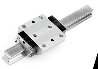
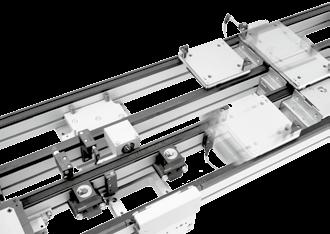
 Product Description Outstanding features Rexroth Feed Modules VKK are precise, ready-to-install linear motion systems that combine high performance with compact dimensions.")

4 4 Feed Modules VKK R310EN 2403 ( ) Product Description Outstanding features Rexroth Feed Modules VKK are precise, ready-to-install linear motion systems that combine high performance with compact dimensions. They are especially suitable for handling tasks requiring high precision as well as high thrust and torque transfer capabilities. Because of their low moved mass, Feed Modules VKK are ideal for vertical motion in Z-axes. Rexroth offers favorable price/performance ratios and fast delivery. Structural design Extremely compact extruded aluminum profile (frame) with zero-clearance Ball Rail System in eline technology Precision Ball Screw Drive in tolerance grade 7 with zero-backlash nut system Fixed bearing end block made of aluminum Further highlights Optimal travel performance, high load capacities and high rigidity due to integrated, zero-clearance ball rail system Especially compact design due to integrated ball screw drive Ball screw drive with zero-backlash nut system assures high positioning accuracy and repeatability Low-cost maintenance provided by one-point lubrication (grease) of the ball rail system and the ball screw drive Easy motor attachment due to locating feature and fastening threads Encapsulated guideway Switches positionable over the entire travel range Switch activation without switching cam Allows easy installation of various attachments Fully compatible with the camoline system Positive-locking connection technology with centering rings Attachments Maintenance-free digital AC servo drives with or without brake and attached feedback Stepping motors with encoder, with or without brake Motor mount and coupling or timing belt side drive for motor attachment Switches Drive controllers and control systems End block with threads and locating feature for motor attachment Thrust rod with mounting interface for standard flange
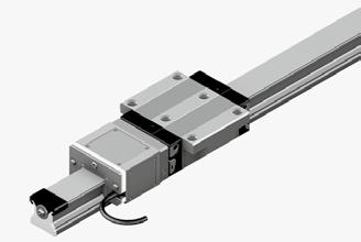
 Feed Modules VKK 5 Motor attachment via timing belt side drive Motor attachment via")

5 R310EN 2403 ( ) Feed Modules VKK 5 Motor attachment via timing belt side drive Motor attachment via motor mount and coupling Without attached motor Centering holes for positive-locking connections with good reproducibility to simplify installation (camoline Cartesian Motion building system) Thrust rod with standard flange for a variety of attachments
6 Hand RS232 Auto 6 Feed Modules VKK R310EN 2403 ( ) Product Overview Motor selection based on drive controllers and control system Several motor-controller combinations are available in order to provide the most cost-effective solution for every customer application. When dimensioning the drive unit, always consider the motor-controller combination. For more detailed information on motors and control systems, please refer to the Rexroth catalogs ECODRIVE Cs and IndraDrive for Linear Motion Systems. Digital AC servo motors MSK Digital controllers IndraDrive Digital AC servo motors MSM Digital controllers ECODRIVE Cs 3-phase stepping motors Power electronics SD326 SD328 Profi Step control unit
 Feed Modules VKK 7 Feed Modules VKK are available as complete")
7 R310EN 2403 ( ) Feed Modules VKK 7 Feed Modules VKK are available as complete solutions with motor, controller and control system.
8 8 Feed Modules VKK R310EN 2403 ( ) Product Overview Type designation (size) Feed Modules VKK are identified by the type designation and size. Description Type Size Example: Feed Module V K K System Feed Module (V) Guideway Integrated Ball Rail System (K) Drive unit Ball Screw (K) Frame size Width of frame (mm) Example: B = 100 mm B B Overview of types with load capacities Type System Guideway Drive unit Feed Module Load capacities C C C C VKK VKK Feed Module Ball rail system Ball screw drive VKK VKK C (N)
9 L R310EN 2403 ( ) Feed Modules VKK 9 Dimensions B B Standard lengths L Feed Module VKK VKK VKK Stroke B (mm) L (mm)
 Structural Design Feed Module VKK 1 Ball screw with zero-backlash cylindrical single nut 2 Fixed bearing end block 3 Frame 4 Thrust rod 5 Mounting interface for standard")
10 10 Feed Modules VKK R310EN 2403 ( ) Structural Design Feed Module VKK 1 Ball screw with zero-backlash cylindrical single nut 2 Fixed bearing end block 3 Frame 4 Thrust rod 5 Mounting interface for standard flange 6 End seal Attachments 7 Magnetic field sensor 8 Motor 9 Motor mount and coupling 10 Timing belt side drive
11 R310EN 2403 ( ) Feed Modules VKK 11 Motor mount and coupling A motor can be attached to all Feed Modules by means of a motor mount and coupling. The motor mount serves to fasten the motor to the Feed Module and acts as a closed housing for the coupling. The motor s drive torque is transmitted stress-free through the coupling to the Feed Module's screw shaft Timing belt side drive All Feed Modules offer the option of attaching the motor via a side drive with timing belt. This results in a shorter overall length compared to a motor attachment via motor mount and coupling. The compact, closed housing protects the belt and secures the motor. Various gear ratios are also available: i = 1 : 1 i = 1 : 1.5 i = 1 : The timing belt side drive can be mounted in four different directions: below, above (RV01 and RV02) left, right (RV03 and RV04) 9 Fpr Motor Motor mount Coupling Fixed bearing end block Feed Module End cover Drawn, anodized aluminum profile Toothed belt Pre-tensioning of the toothed belt: apply pretensioning force F pr to motor (F pr will be indicated on delivery) Belt pulleys Cover plate
12 12 Feed Modules VKK R310EN 2403 ( ) Technical Data Load capacities and moments Feed Module Ball screw Dynamic load capacity C Dynamic moments Planar moment of inertia z Thrust rod y y Maximum stroke Maximum moved mass of system Guideway screw bearing M t Ball Fixed z M L l y l z H max m b d 0 x P (N) (N) (N) (Nm) (Nm) (cm 4) (cm 4) (mm) (kg) VKK x x x VKK x x x VKK x x x Maximum permissible loads Feed Module Maximum permissible forces Maximum permissible moments F z max F y max M t max M L max (N) (N) (Nm) (Nm) VKK VKK VKK Acceptable loads (recommended from experience) As far as the desired service life is concerned, loads of up to approximately 20% of the dynamic load and moment values (C, M t, M L ) have proved acceptable. At the same time, the following may not be exceeded: maximum permissible loads permissible drive torque permissible travel speed Note on dynamic load capacities and moments Determination of the dynamic load capacities and moments is based on a travel life of 100,000 m. Often only 50,000 m are actually stipulated. For comparison: Multiply values C, M t and M L from the table by Maximum permissible drive torque for mechanical system M mech Requirement: No radial load on ball screw shaft Consider the rated torque of the coupling used! Maximum permissible linear speed of mechanical system v mech Consider the motor speed! Feed Module Ball screw M mech M mech with key Travel speed v mech d 0 x P (Nm) (Nm) (m/s) VKK x x x VKK x x x VKK x x x Modulus of elasticity E E = 70,000 N/mm 2 Weight of Feed Module without motor VKK 15-50: 1.05 kg (kg/mm). stroke (mm) VKK 15-70: 2.8 kg (kg/mm). stroke (mm) VKK : 7.2 kg (kg/mm). stroke (mm) d 0 = screw diameter (mm) P = screw lead (mm) Ball screw = ball screw size d 0 x P
13 R310EN 2403 ( ) Feed Modules VKK 13 Specifications of timing belt side drive for motor attachment via timing belt side drive Motor MSM 030 B Frictional torque M Rsd (Nm) 0.35 Permissible torque Reduced mass moment of inertia at Gear ratio i = 1 i = 1.5 i = 1 i = 1.5 Feed Module Ball screw M sd M sd J sd J sd d 0 x P (Nm) (Nm) (10-6 kgm 2 ) (10-6 kgm 2 ) VKK x x x Motor MSM 030 C MSM 040B Frictional torque M Rsd (Nm) Permissible torque Reduced mass moment of inertia at Permissible torque Reduced mass moment of inertia at Gear ratio i = 1 i = 1.5 i = 1 i = 1.5 i = 1 i = 1.5 i = 1 i = 1.5 Feed Module Ball screw M sd M sd J sd J sd M sd M sd J sd J sd d 0 x P (Nm) (Nm) (10-6 kgm 2 ) (10-6 kgm 2 ) (Nm) (Nm) (10-6 kgm 2 ) (10-6 kgm 2 ) VKK x x x VKK x x x Motor MSK 030 C MSK 050 C Frictional torque M Rsd (Nm) Permissible torque Reduced mass moment of inertia at Permissible torque Reduced mass moment of inertia at Gear ratio i = 1 i = 1.5 i = 1 i = 1.5 i = 1 i = 2 i = 1 i = 2 Feed Module Ball screw M sd M sd J sd J sd M sd M sd J sd J sd d 0 x P (Nm) (Nm) (10-6 kgm 2 ) (10-6 kgm 2 ) (Nm) (Nm) (10-6 kgm 2 ) (10-6 kgm 2 ) VKK x x x VKK x x x VKK x x x M Rsd = frictional torque of timing belt side drive at motor journal (Nm) M sd = permissible torque for system with timing belt side drive at motor journal (Nm); consider max. permissible motor torque M max J sd = reduced mass moment of inertia of timing belt side drive (kgm 2 ) i = timing belt side drive reduction
14 14 Feed Modules VKK R310EN 2403 ( ) Technical Data Specifications of timing belt side drive for motor attachment via timing belt side drive Constants k j fix, k j var, k j m Frictional torque M Rsd The constants are required to determine the mass moment of inertia of the system J s. Feed Module Ball screw Constants Frictional torque d 0 x P k j fix k j var k j m M Rsd (Nm) VKK x x x VKK x x x VKK x x x Coupling data Feed Module Motor attachment Coupling data Rated torque Mass moment of Weight M cn inertia J c (Nm) (10-6 kgm 2 ) (kg) VKK MSM 020B MSM 030B MSM 030C VRDM VKK MSM 030C MSM 040B MSK 030C MSK 040C VRDM 3910 VRDM 3913 VKK MSM 040 B MSK 050C VRDM
15 R310EN 2403 ( ) Feed Modules VKK 15 Rigidity of thrust rod Feed Module VKK Measured values Key to graph a Stroke = 400 mm b Stroke = 320 mm c Stroke = 200 mm d Stroke = 120 mm e Stroke = 80 mm δ el = elastic deflection M L = dynamic longitudinal moment load capacity (mm) (Nm) Rigidity in y-direction (mm) 1,5 1,35 1,2 1,05 0,9 0,75 0,6 0,45 0,3 0, ,5 3 4,5 6 7,5 9 10, ,5 15 M L (Nm) a b c d e Rigidity in z-direction (mm) 1,5 1,35 1,2 1,05 0,9 0,75 0,6 0,45 0,3 0,15 a b c d e 0 0 1,5 3 4,5 6 7,5 9 10, ,5 15 M L (Nm)
16 16 Feed Modules VKK R310EN 2403 ( ) Technical Data Rigidity of thrust rod Feed Module VKK Rigidity in y-direction Measured values Key to graph a Stroke = 400 mm b Stroke = 320 mm c Stroke = 200 mm d Stroke = 120 mm e Stroke = 80 mm δ el = elastic deflection M L = dynamic longitudinal moment load capacity (mm) (Nm) (mm) 2 1,8 1,6 1,4 1,2 1,0 0,8 0,6 0,4 0, M L (Nm) a b c d e Rigidity in z-direction (mm) 2 1,8 1,6 1,4 1,2 1,0 0,8 0,6 0,4 0,2 a b c d e M L (Nm)
17 R310EN 2403 ( ) Feed Modules VKK 17 Rigidity of thrust rod Feed Module VKK Rigidity in y-direction Measured values Key to graph a Stroke = 400 mm b Stroke = 320 mm c Stroke = 200 mm d Stroke = 120 mm e Stroke = 80 mm δ el = elastic deflection M L = dynamic longitudinal moment load capacity (mm) (Nm) (mm) 5 4,5 4 3,5 3 2,5 2 1,5 1 0, M L (Nm) a b c d e Rigidity in z-direction (mm) 5 4,5 4 3,5 3 2,5 2 1,5 1 0, M L (Nm) a b c d e
18 18 Feed Modules VKK R310EN 2403 ( ) Calculations (T + stroke eff ) = center-to-center distance between runner block and mounting interface Feed Module T (mm) VKK VKK VKK M x M Lmax M t max F z max F y max M Lmax C C F z max F y max M z F M y T + stroke eff Combined equivalent load on bearing of the linear guide F = F M x comb y + Fz + C M + C M y + C t M L M z M L Nominal life Nominal life of the guideway in meters: Nominal life of the guideway in hours: Frictional torque for motor attachment via motor mount and coupling: for motor attachment via timing belt side drive: Mass moment of inertia of the linear motion system J s referred to the drive journal L m = L h = M R = 3 C 10 5 m F comb L m 3600 v m M R = M Rs M Rs i + M R sd J s = (k J fix + k J var L) 10 6 C = dynamic load capacity (N) F comb = combined equivalent load on bearing (N) F y = force in y-direction (N) F z = force in z-direction (N) i = gear ratio J s = mass moment of inertia of linear motion system (without external load) (kgm 2 ) k J fix = constant for fixed-length portion of mass moment of inertia (kgm 2 ) k J var = constant for variable-length portion of mass moment of inertia (10 6 kgm) L m = nominal life in meters (m) L = length of Feed Module (m) L h = nominal life in hours (h) M L = dynamic longitudinal moment load capacity (Nm) M R = frictional torque at motor journal (Nm) M Rs = frictional torque of the system (Nm) M R sd = frictional torque of timing belt side drive at motor journal (Nm) M t = dynamic torsional moment load capacity (Nm) M x = torsional moment about the x-axis (Nm) M y = torsional moment about the y-axis (Nm) M z = torsional moment about the z-axis (Nm) v m = average travel speed (m/s) y 1, z 1 = application point of the effective force (mm)
19 R310EN 2403 ( ) Feed Modules VKK 19 Calculations Mass moment of inertia of the mechanical system referred to the motor journal Motor attachment via motor mount and coupling: Motor attachment via timing belt side drive: Translatory mass moment of inertia of external load referred to the drive journal Mass moment of inertia of the drive train referred to the motor journal Mass moment of inertia ratio Total mass moment of inertia referred to the motor journal J ex = J s + J t + J c J ex = J s + J t i 2 + J sd J t = m ex k J m 10 6 J dc = J ex + J br V = J dc J m Application area V Handling 6.0 Processing 1.5 J tot = J dc + J m J br = mass moment of inertia, motor brake (kgm 2 ) J c = mass moment of inertia, coupling (kgm 2 ) J dc = mass moment of inertia, drive train (kgm 2 ) J ex = mass moment of inertia of mechanical system (kgm 2 ) J m = mass moment of inertia, motor (kgm 2 ) J s = mass moment of inertia of linear motion system (without external load) (kgm 2 ) J sd = mass moment of inertia of timing belt side drive at motor journal (kgm 2 ) J t = translatory mass moment of inertia of external load referred to the drive journal (kgm 2 ) J tot = total mass moment of inertia (kgm 2 ) i = gear ratio of timing belt side drive ( ) k J m = constant for mass-specific portion of mass moment of inertia (10 6 m 2 ) m ex = moved external load (kg) n m max = maximum permissible rotary speed of motor with controller (min 1 ) n mech = maximum permissible rotary speed of mechanical system (min 1 ) P = screw lead (mm) V = ratio of mass moments of inertia of drive train and motor ( ) v mech = maximum permissible linear speed of mechanical system (m/s) Maximum permissible rotary speed for mechanical system n mech = v mech i P n mech < n m max
20 20 Feed Modules VKK R310EN 2403 ( ) Feed Module VKK Part number, length R ,... mm Components and Ordering Data Guideway Drive unit Carriage (internal) Type With ball screw, without motor mount With ball screw and motor mount With ball screw and timing belt side drive OF1 MF01 RV01 1) RV02 RV03 RV04 OF01 L = 240 mm 12 L = 280 mm 13 Screw journal Ball screw size d 0 x P 12x2 12x5 12x10 Without standard flange With standard flange MF01 L = 360 mm Ø RV01 to RV04 L = 480 mm 18 L = 560 mm 20 Ø Ø Order example: See Inquiry/Order Form c Please check whether the selected combination is a permissible one (load capacities, moments, maximum speeds, motor data, etc.)! 1) d 0 P Consider the position of the lube ports! Please refer to the Lubrication section. 44 = screw diameter (mm) = screw lead (mm) For details of standard flange 41.
21 R310EN 2403 ( ) Feed Modules VKK 21 Motor attachment Motor 1st, 2nd, 3rd switch Documentation Gear ratio i = Attachment kit 2) for motor Standard report Measurement report without brake with brake Without switch Magnetic field sensor: Reed sensor MSM 020B MSK 030C i = 1 03 MSM 030B VRDM i = 1 23 MSM 030 B i = Hall sensor (PNP NC) 22 Magnetic field sensor with connector: Reed sensor 58 Hall sensor (PNP NC) Frictional torque 03 Lead deviation 05 Positioning accuracy i = 1 21 i = MSK 030C ) Attachment kit also available without motor (when ordering: enter 00 for motor). Switch Mounting Arrangements Refer to Switch mounting arrangements for more information on switch types and switch mounting 32.
22 22 Feed Modules VKK R310EN 2403 ( ) Feed Module VKK Dimension drawings All dimensions in mm Drawings not to scale A ,5 A 7 H7 Ø28 H7 Ø6 h7 Ø20 h7 Ø19 Max. travel Excess travel Effective stroke Excess travel 2, N x 40 ±0,01 20 L = stroke Length L Stroke eff N Moved mass of system Excess travel Ball screw 12x2 Ball screw 12x5 Ball screw 12x10 (mm) (mm) ( ) (kg) (mm) (mm) (mm) Type OF01 Type MF01 Type RV01, RV02, RV03, RV04 X Ø28 H7 Ø6 h7 2, D L m L f X F L sd E K G L m D
23 R310EN 2403 ( ) Feed Modules VKK 23 M4-8 deep 4x A 2,8 B 3,2 1,3 3,2 C 4,8 2,5 4, A T-slot for switches B 6 3,5 3 6,8 C 5,2 14,5 Type Motor Dimensions (mm) D E F G K L f L m L sd i = 1 i = 1.5 without brake with brake i = 1 i = 1.5 RV01 to RV04 MSM 030B MSK 030C MF01 MSM 020B MSM 030B MSK 030C VRDM Version with standard flange For details of standard flange Ø75
24 24 Feed Modules VKK R310EN 2403 ( ) Feed Module VKK Part number, length R ,... mm Components and Ordering Data Guideway Drive unit Carriage (internal) Type With ball screw, without motor mount With ball screw and motor mount With ball screw and timing belt side drive OF1 MF01 RV01 1) RV02 RV03 RV04 OF01 L = 280 mm 12 L = 320 mm 13 Screw journal Ball screw size d 0 x P 16x5 16x10 16x16 Without standard flange With standard flange MF01 L = 400 mm Ø RV01 to RV04 L = 520 mm 18 L = 600 mm 20 Ø Ø 9 Keyway Ø Order example: See Inquiry/Order Form c Please check whether the selected combination is a permissible one (load capacities, moments, maximum speeds, motor data, etc.)! 1) d 0 P Consider the position of the lube ports! Please refer to the Lubrication section. 44 = screw diameter (mm) = screw lead (mm) For details of standard flange 41.
25 R310EN 2403 ( ) Feed Modules VKK 25 Motor attachment Motor 1st, 2nd, 3rd switch Documentation Gear ratio i = Attachment kit 2) for motor Standard report Measurement report without brake with brake Without switch Magnetic field sensor: Reed sensor MSM 030C MSK 030C i = 1 03 MSM 040B MSK 040C VRDM VRDM i = 1 23 MSM 030 C i = Hall sensor (PNP NC) 22 Magnetic field sensor with connector: Reed sensor 58 Hall sensor (PNP NC) Frictional torque 03 Lead deviation 05 Positioning accuracy i = 1 21 i = MSK 030C ) Attachment kit also available without motor (when ordering: enter 00 for motor). Switch Mounting Arrangements Refer to Switch mounting arrangements for more information on switch types and switch mounting 32.
26 26 Feed Modules VKK R310EN 2403 ( ) Feed Module VKK Dimension drawings All dimensions in mm Drawings not to scale A ,5 A 9 H7 Ø40 H7 Ø9 h7 Ø20 h7 Ø19 Excess travel Max. travel Effective stroke Excess travel 2, N x 40±0,01 20 L = stroke Length L Stroke eff N Moved mass of system Excess travel Ball screw 16x5 Ball screw 16x10 Ball screw 16x16 (mm) (mm) ( ) (kg) (mm) (mm) (mm) Type OF01 2,5 Type MF01 Type RV01, RV02, RV03, RV04 X Ø9 h7 Ø40 H7 25 2,5 3 P9 h = 1,8 20 D L m L f X F L sd E K G L m D
27 R310EN 2403 ( ) Feed Modules VKK 27 M6-14 deep 4x 40 B C 3 9,5 8,2 5, ,5 6, Ø9 H7 2,1 T-slot for switches B 40 C 2,5 4, ,2 14,5 Type Motor Dimensions (mm) D E F G K L f L m L sd i = 1 i = 1.5 without brake with brake i = 1 i = 1.5 RV01 to RV04 MSM 030C MSK 030C MF01 MSM 030C MSM 040B MSK 030C MSK 040C VRDM VRDM Version with standard flange For details of standard flange Ø75
28 28 Feed Modules VKK R310EN 2403 ( ) Feed Module VKK Part number, length R ,... mm Components and Ordering Data Guideway Drive unit Carriage (internal) Type With ball screw, without motor mount With ball screw and motor mount OF1 MF01 OF01 L = 360 mm 12 Screw journal Ball screw size d 0 x P 20x5 25x10 20x20 Without standard flange With standard flange L = 400 mm MF01 13 Ø L = 480 mm 15 Ø Ø 14 Keyway RV01 1) RV02 L = 600 mm 18 With ball screw and timing belt side drive RV03 RV04 RV01 to RV04 L = 680 mm 20 Ø Order example: See Inquiry/Order Form c Please check whether the selected combination is a permissible one (load capacities, moments, maximum speeds, motor data, etc.)! 1) d 0 P Consider the position of the lube ports! Please refer to the Lubrication section. 44 = screw diameter (mm) = screw lead (mm) For details of standard flange 41.
29 R310EN 2403 ( ) Feed Modules VKK 29 Motor attachment Motor 1st, 2nd, 3rd switch Documentation Gear ratio i = Attachment kit 1) for motor Standard report Measurement report without brake with brake Without switch Magnetic field sensor: Reed sensor 21 Hall sensor (PNP NC) MSM 040B MSK 050C VRDM Magnetic field sensor with connector: Reed sensor 58 Hall sensor (PNP NC) Frictional torque 03 Lead deviation i = 1 27 i = MSM 040B Positioning accuracy i = 1 29 i = 2 30 MSK 050C ) Attachment kit also available without motor (when ordering: enter 00 for motor). Switch Mounting Arrangements Refer to Switch mounting arrangements for more information on switch types and switch mounting.
30 30 Feed Modules VKK R310EN 2403 ( ) Feed Module VKK Dimension drawings All dimensions in mm Drawings not to scale A Ø19 7,5 A Max. travel 12 H7 Excess travel Effective stroke Excess travel Ø55 J6 Ø14 h7 Ø20 h N x 40±0,01 20 L = stroke Lenght L Stroke eff N Moved mass of system Excess travel Ball screw 20x5 Ball screw 25x10 Ball screw 20x20 (mm) (mm) ( ) (kg) (mm) (mm) (mm) Type OF01 Type MF01 Type RV01, RV02, RV03, RV04 3 X Ø55 J6 Ø14 h h = D L m L f X F L sd E K G L m D
31 R310EN 2403 ( ) Feed Modules VKK 31 M8-18 deep 8x B C 9,5 8,2 5,2 11 3,5 3 6, Ø12 H7 2,1 T-slot for switches B 60 C 2,5 4,8 16,5 8,1 4,2 5,2 14,5 Type Motor Dimensions (mm) D E F G K L f L m L sd i = 1 i = 1.5 i = 2 without brake with brake i = 1 i = 1.5 i = 2 RV01 to RV04 MSM 040B MSK 050C MF01 MSM 040B MSK 050C VRDM Version with standard flange For details of standard flange Ø75
 Switch Mounting Arrangements Overview of switching system 1 2 Switch (magnetic field sensor) T-slot for switch Cable 3 The switch activator is a magnet integrated in the")
 or Reed sensor (changeover) Switching system 1 2 Mounting instructions The magnetic field sensors (MFS) are pushed into the T-slot and fixed with")
32 32 Feed Modules VKK R310EN 2403 ( ) Switch Mounting Arrangements Overview of switching system 1 2 Switch (magnetic field sensor) T-slot for switch Cable 3 The switch activator is a magnet integrated in the thrust rod. c For short-stroke applications: Consider the length of the switch! Magnetic field sensors with potted cables can be used in the Feed Module. Type Hall sensor (PNP NC) or Reed sensor (changeover) Switching system 1 2 Mounting instructions The magnetic field sensors (MFS) are pushed into the T-slot and fixed with set screws. The MFS cables are routed along the side of the T-slot (3). For details regarding the switching position, see Instructions for Feed Modules
33 R310EN 2403 ( ) Feed Modules VKK 33 Switch Mounting Arrangements Magnetic field sensor Magnetic field sensor with potted cable. 3 Part number Hall sensor R Reed sensor R Active surface 35 Set screw for fixing Magnetic field sensor with connector Set screw M3 Magnetic field sensor with potted cable and connector. 6,5 Part number Hall sensor R Reed sensor R Ø2,9 Activation point X ±0,2 Pin assignment Hall sensor White: Green: V DC Output Reed sensor 1 4 Brown White Brown: 3 0V ground 3 Green Technical data For magnetic field sensors with and without connector. Hall sensor Contact type PNP NC Operating voltage V DC Current consumption max. 10 ma Output current max. 20 ma Cable length 2 m (10 m on request) Protection class IP 66 Short-circuit protection No Max. travel speed 2 m/s Dimension X mm Reed sensor Contact type Changeover Switching voltage max. 100 V DC Switching current max. 500 ma Cable length 2 m (10 m on request) Protection class IP 66 Max. travel speed 2 m/s Switching points 2 Dimension X 9 mm
34 34 Feed Modules VKK R310EN 2403 ( ) Motors AC servo motors MSK Notes All MSK motors have an absolute multiturn encoder. H The motors can be supplied complete with controller and control unit. For more information on motors, controllers and control systems, please refer to the Rexroth catalogs ECODRIVE Cs and IndraDrive for Linear Motion Systems. ØE ØD B 3 H 2 A ØG H 1 R B 2 B 1 L 1 L A ØF Dimensions Motor Dimensions (mm) A B 1 B 2 B 3 ØD ØE ØF ØG H 1 H 2 H 3 L w/o L with L 1 R k6 j6 brake brake MSK 030C R5 MSK 040C R8 MSK 050C R8 Motor data Motor Unit MSK 030C-0900 MSK 040C-0600 MSK 050C-0600 Maximum rotary speed n max (min 1 ) Maximum permissible torque M max (Nm) Rated torque M N (Nm) Motor mass moment of inertia J m (10 6 kgm 2 ) Mass without brake m m (kg) Holding brake Holding torque M br (Nm) Brake mass moment of inertia J br (10 6 kgm 2 ) Mass of brake m br (kg)
35 R310EN 2403 ( ) Feed Modules VKK 35 Motors AC servo motors MSM Notes All MSM motors have an absolute multiturn encoder. 45 The motors can be supplied complete with controller and control unit. For more information on motors, controllers and control systems, please refer to the Rexroth catalogs ECODRIVE Cs and IndraDrive for Linear Motion Systems. ØE ØD B 3 H 3 H 2 A ØG H 1 B 2 B 1 L A ØF Dimensions Motor Dimensions (mm) A B 1 B 2 B 3 ØD ØE ØF ØG H 1 H 2 H 3 L L h6 h7 without brake with brake MSM 020B MSM 030B MSM 030C MSM 040B Motor data Motor Unit MSM 020B MSM 030B MSM 030C MSM 040B Maximum rotary speed n max (min 1 ) Maximum permissible torque M max (Nm) Rated torque M N (Nm) Motor mass moment of inertia J m (10 6 kgm 2 ) Mass without brake m m (kg) Holding brake Holding torque M br (Nm) Brake mass moment of inertia J br (10 6 kgm 2 ) Mass of brake m br (kg)
36 36 Feed Modules VKK R310EN 2403 ( ) Motors 3-phase stepping motors VRDM Motor connector Brake Encoder connector Brake connector All VRDM motors are equipped with an encoder. VRDM 368 B 1 L ± 0,5 41 Ø E Ø D B 3 B Ø15 Ø A Ø F Ø G VRDM 3910, 3913, B 1 B 2 L +0,7 46, Ø G ØE ØD 22,5 32,5 Ø15 Ø83,5 A 60 B ØF Motor Dimensions (mm) A B 1 B 2 B 3 ØD ØE ØF ØG L L w/o brake with brake VRDM ± VRDM h h VRDM h8 14 h VRDM h8 19 h Motor data Motor Unit VRDM 368 VRDM 3910 VRDM 3913 VRDM Maximum permissible torque M max (Nm) Motor mass moment of inertia J m (10 6 kgm 2 ) Motor holding torque M m (Nm) Mass without brake m m (kg) Step count z ( ) 200 / 400 / 500 / 1000 / / / / Stepping angle per step a ( ) 1.8 / 0.9 / 0.72 / 0.36 / 0.18 / 0.09 / / Encoder resolution 1000 increments/revolution Holding brake Brake holding torque M br (Nm) Brake mass moment of inertia J br (10 6 kgm 2) Mass of brake m br (kg)
37 R310EN 2403 ( ) Feed Modules VKK 37 Mounting General notes Fastening with clamping fixtures The modules are mounted using clamping fixtures which engage in the T-slots on the side of the frame. Clamping fixtures Feed Module Dimensions (mm) A B VKK VKK VKK A± 0,1 B Mounting surface The Feed Module may only be installed/ connected to other modules by the mounting surface with the centering holes. Mounting surface Centering holes T-slot for switches
 Mounting Accessories Clamping fixtures H Recommended number of clamping fixtures: Type 1: 4 pieces per side Type 2: 2 pieces per side/per 300 mm Type 3: 1 piece per side/per 300 mm G F E D")
38 38 Feed Modules VKK R310EN 2403 ( ) Mounting Accessories Clamping fixtures H Recommended number of clamping fixtures: Type 1: 4 pieces per side Type 2: 2 pieces per side/per 300 mm Type 3: 1 piece per side/per 300 mm G F E D Countersink for thread M ISO 4762 Number N A C C B C A B C A Feed Module For thread Type 1 Type 2 Type 3 Type Number of holes Dimensions (mm) Part number N A B C D E F G H VKK M R R R VKK M R R VKK VKK M R R R R R Centering ring The centering ring serves as a positioning aid and for positive locking when mounting customer attachments to the carriage. It creates a positive-locking connection with good reproducibility. Material: steel (stainless) D ØF ØC ØA ØB D ØF ØC ØA H 1 Installation ØA H7 a b c ØB H7 ØA H7 H 1 H 2 E Ø Dimensions (mm) Part number a) Customer s attachment b) Centering ring c) Carriage A B C D E ØF H 1 H 2 (mm) k6 k6 ± R R R R R R R R R R
39 R310EN 2403 ( ) Feed Modules VKK 39 Extraction tool for centering rings The tool is used to grip the centering ring through the cross-holes for easy extraction. Part number: R Sliding blocks and springs For mounting attachments using the T-slots D A C B M E M M 1 E Feed Module For thread Dimensions (mm) Part number A B C D E M 1 Sliding block Spring VKK M4 VKK M R R M R M5 12 R R VKK M R R M5 16 R R M6 16 R R M R Tightening torques of the fastening screws at friction factor Strength class Nm max. M4 M5 M6 M
40 40 Feed Modules VKK R310EN 2403 ( ) Mounting to Installed Modules No intermediate plates required Positive locking via centering rings (camoline compatible) Easy mounting with clamping fixtures Feed Module VKK mounted to Compact Module CKK Feed Module VKK mounted to Bridge Module BKK
 Feed Modules VKK Connection Elements Standard flange Function Connection of customer attachments Kit consisting of: 1 Standard flange 2 Set screw (2x M10x12, ISO 4026) 2 Note for ordering The")
41 R310EN 2403 ( ) Feed Modules VKK Connection Elements Standard flange Function Connection of customer attachments Kit consisting of: 1 Standard flange 2 Set screw (2x M10x12, ISO 4026) 2 Note for ordering The standard flange can ONLY be ordered by specifying carriage option 02 (carriage with standard flange). 1 Mounting instructions The standard flange is fastened to the mounting interface on the thrust rod of the Feed Module using two M10 set screws. c Push the standard flange onto the mounting interface until it reaches the mechanical stop. c If the standard flange is removed, the set screws must be secured again when it is re-installed! (For example with liquid mediumstrength threadlocker adhesive.) Tightening torque for the set screws 30 Nm Ø12H deep 0 60 ISO 4026 M10 x 12 M4 Ø7H Ø20H7 Ø50 Ø6 Ø4 Ø75 M5 Ø9H7 M6 1.6 deep Locating holes for centering rings 41
 Connection Elements Connection of Gripper GSP Function Connection of Pneumatic Grippers, Type GSP (camoline range) 5 Kit consisting of: 1 Connection plate 2 Mounting screws 3")
. For details and dimensions 41.")
 Gripper GSP Connection plate kit Part number 10 16 20 25 32 6 R1419 000 25 R1419 000 26 R1419 000 27 R1419 000 28 R1419 000 29 Weight (kg) 0.")
42 42 Feed Modules VKK R310EN 2403 ( ) Connection Elements Connection of Gripper GSP Function Connection of Pneumatic Grippers, Type GSP (camoline range) 5 Kit consisting of: 1 Connection plate 2 Mounting screws 3 Centering rings 4 2 Additional parts (not included in kit): 4 Standard flange 5 Set screws (M10x12, ISO 4026) 6 Gripper GSP Mounting instructions The standard flange (4) is required for mounting of the connection plate. Please order this by specifying carriage option 02 (carriage with standard flange). For details and dimensions 41. c If the standard flange is removed, the set screws must be secured again when it is re-installed! (For example with liquid mediumstrength threadlocker adhesive.) Gripper GSP Connection plate kit Part number R R R R R Weight (kg) 0.2 Tightening torques for the fastening screws Tightening torque for the standard flange set screws For details of the Gripper types, please refer to the camoline catalog Nm Nm max. M3 M4 M5 M6 M
 Feed Modules VKK 43 Connection of Rotary Compact Module RCM Function Connection of Rotary Compact Modules, Type RCM (camoline range) 2 Key to illustration 1 Standard flange 2 Set screws (M10x12,")
. For details and dimensions 41.")
43 R310EN 2403 ( ) Feed Modules VKK 43 Connection of Rotary Compact Module RCM Function Connection of Rotary Compact Modules, Type RCM (camoline range) 2 Key to illustration 1 Standard flange 2 Set screws (M10x12, ISO 4026) 3 Centering rings 4 Rotary Compact Module RCM 5 Fastening screws (not included in delivery) 1 Mounting instructions The standard flange is required for mounting of the Rotary Compact Module RCM. Please order this by specifying carriage option 02 (carriage with standard flange). For details and dimensions c If the standard flange is removed, the set screws must be secured again when it is re-installed! (For example with liquid mediumstrength threadlocker adhesive.) Rotary Compact Module RCM Required fastening screws M4x25 ISO M5x30 ISO M5x40 ISO M6x45 ISO M6x50 ISO Tightening torques for the fastening screws Tightening torque for the standard flange set screws For details of the Rotary Compact Module types, please refer to the camoline catalog. 4 5 Quantity Nm Nm max. M3 M4 M5 M6 M
.")
44 44 Feed Modules VKK R310EN 2403 ( ) Lubrication Lubrication notes Basic lubrication is applied in-factory before shipment. Feed Modules are designed for grease lubrication (using a manual grease gun with an extension tube and nozzle). The only maintenance required is lubrication of the guideway and the ball screw via the two lube ports. Lubricant must be applied to both of the lube ports. The thrust rod must be fully extended before applying lubricant. When designing the adjoining structure, make sure that the maximum stroke may be attained. 1 2 b a Lube ports for: 1 Runner blocks 2 Ball screw Recommended lubricants For lubricant quantities and intervals, see Mounting Instructions for Feed Modules. c Do not uses greases containing solid particles (e.g., graphite or MoS 2 )! Feed Module Grease DIN Consistency class DIN Recommended grease Part number (400 g cartridge) VKK VKK KP2K NLGI 2 Dynalub 510 R VKK Dimensions of lube ports Feed Module a (1) (mm) b (2) (mm) VKK VKK VKK
45 R310EN 2403 ( ) Feed Modules VKK 45 Documentation Standard report Option no. 01 The standard report serves to confirm that the checks listed in the report have been carried out and that the measured values lie within the permissible tolerances. Checks listed in the standard report: functional checks of mechanical components functional checks of electrical components design is in accordance with order confirmation Frictional torque of complete system Advance Return Example Option no. 02 Moment of friction M The moment of friction M is measured over the entire travel range. M (Nm) 0 Moment of friction M M = moment of friction (N) t = travel time (ms) t (ms) Lead deviation of the ball screw Example Option no. 03 A measurement report of the lead deviation d over the measured travel s (see illustration) is provided in table form in addition to the graph. 0 d = deviation (mm) s = measured travel (mm) 0 s (mm)
46 46 Feed Modules VKK R310EN 2403 ( ) Documentation Positioning accuracy per VDI/DGQ 3441 Option no. 05 Measurement points are selected at irregular intervals along the travel range. This allows even periodical deviations d in mm to be detected during positioning. Each measurement point is approached several times from both sides. This gives the following parameters P a P Example P s/2 P s/2 U d = deviation (mm) s = measured travel (mm) , , , ,5 700 s (mm) Positioning accuracy P Position deviation P a Reversal range U Position variation range P s The positioning accuracy corresponds to the total deviation. It encompasses all the systematic and random deviations during positioning. The position deviation corresponds to the maximum difference arising in the mean values of all the measurement points. It describes systematic deviations. The reversal range corresponds to the difference in mean values of the two approach directions. The position variation range describes the effects of random deviations. It is determined at every measurement point. The positioning accuracy takes the following characteristic values into consideration: position deviation reversal range position variation range The reversal range is determined at every measurement point. It describes systematic deviations.
47 R310EN 2403 ( ) Feed Modules VKK 47 Inquiry/Order Form Linear Motion and Assembly Technologies Schweinfurt Germany Telephone Telefax (direct) Rexroth Feed Module VKK Order Example Ordering data Explanation Option Option code Feed Module VKK Feed Module, length 480 mm Part number, length R , 480 mm Type MF01 With motor mount for motor attachment Guideway 15 Integrated ball rail system Drive unit 02 Ball screw, size d 0 x P = 25 x 10 Carriage 02 Carriage (internal) with standard flange Motor attachment 05 For motor MSK 050C Motor 89 Motor MSK 050C with brake 1st switch 21 Reed sensor 2nd switch 22 Hall sensor, PNP NC 3rd switch 21 Reed sensor Documentation 01 Standard report To be completed by customer: Inquiry / Order Feed Module VKK Part number: R, length mm Type = Guideway = Drive unit = Carriage = Motor attachment = Motor = 1st switch = - + mm 2nd switch = - ± mm 3rd switch = - mm Documentation = Individual parts (e.g. accessories, connection elements): Part number: R R R R Quantity Order of: pcs, per month, per year, per order, or Comments: From Company: Name: Address: Department: Telephone: Telefax:
48 Linear Motion and Assembly Technologies Ernst-Sachs-Straße Schweinfurt, Germany Tel Fax Australia Bosch Rexroth Pty. Ltd. 3 Valediction Road Kings Park, NSW 2148, Sydney Tel Fax Great Britain Bosch Rexroth Limited Cromwell Road St. Neots, Huntingdon Cambs. PE19 2ES Tel Fax Canada Bosch Rexroth Canada Corp Mainway Drive Burlington, Ontario L7M 1A8 Tel Fax USA Bosch Rexroth Corporation South Lakes Drive Charlotte, NC Tel REXROTH Fax Singapore Bosch Rexroth Pte. Ltd. 15D Tuas Road Singapore Tel Fax Your sales partner Subject to technical modifications 2008 Printed in Germany R310EN 2403 ( ) EN BRL/MKT2
Product Description. Further highlights. Outstanding features. 4 Bosch Rexroth Corporation Miniature Linear Modules R310A 2418 (2009.
 4 Bosch Rexroth orporation Miniature Linear Modules R310A 2418 (2009.05) Product Description Outstanding features Rexroth Miniature Linear Modules are precise, ready-to-install linear motion systems that
Product description. Compact Modules. Characteristic features. Further highlights
 4 Compact Modules Product description Characteristic features Five fine-tuned sizes based on a compact precision aluminum profile with two integrated pre-tensioned ball rail systems Identical external
Identification system for short product names. Changes/amendments at a glance. 2 Bosch Rexroth AG OBB omega modules R ( )
") Omega Modules OBB 2 OBB omega modules R9990079 (206-05) Identification system for short product names Short product name Example: O B B - 085 - N N - System = Omega module Guideway = Ball Rail System Drive
Omega Modules OBB 2 OBB omega modules R9990079 (206-05) Identification system for short product names Short product name Example: O B B - 085 - N N - System = Omega module Guideway = Ball Rail System Drive
Drive Units with Ball Screw Drives R310EN 3304 ( ) The Drive & Control Company
 The Drive & Control Company") Drive Units with Ball Screw Drives R310EN 3304 (2007.05) The Drive & Control Company Linear Motion and Assembly Technologies Ball Rail Systems Roller Rail Systems Linear Bushings and Shafts Precision Ball
Drive Units with Ball Screw Drives R310EN 3304 (2007.05) The Drive & Control Company Linear Motion and Assembly Technologies Ball Rail Systems Roller Rail Systems Linear Bushings and Shafts Precision Ball
Cam Roller Guides. The Drive and Control Company. Service Automation. Electric Drives and Controls. Linear Motion and Assembly Technologies
 Industrial Hydraulics Electric Drives and Controls Linear Motion and Assembly Technologies Pneumatics Service Automation Mobile Hydraulics Cam Roller Guides The Drive and Control Company Linear Motion
CTV series CHARACTERISTICS LINEAR UNITS
 CTV series CHARACTERISTICS The CTV series describes s with a precision ball screw drive and two parallel, integrated, Zerobacklash rail guides. Compact dimensions allow high performance features such as,
Linear guide drives. Synchronous shafts The use of synchronous shafts enables several linear axes to be operated with one drive.
 Linear guide drives Drive concept The linear guides are driven via the hollow shaft in the drive head. The drive head is used to directly install a motor or alternatively (in connection with a center shaft)
Linear Motion Slides. The Drive and Control Company. Service Automation. Electric Drives and Controls. Linear Motion and Assembly Technologies
 Industrial Hydraulics Electric Drives and Controls inear Motion and ssembly Technologies Pneumatics Service utomation Mobile Hydraulics inear Motion Slides The Drive and Control Company The Product Range
LINE TECH Linear Modules. Ready to built-in linear modules with drive
 Ready to built-in linear modules with drive Anodized profile, produced in extrusion molding method Linear rail guiding system (LM3 LM5) Actuation by ball screw, high-helix lead _ screw or toothed belt
Digital AC Motors MHD
 Digital AC Motors MHD090 8-1 8 MHD090 8.1 Technical Data Description Symbol Unit MHD090B-035 Type of cooling Natural Natural Surface Liquid Motor overtemperature 60 K 100 K 60 K/100 K 60 K/100 K Electric
Precision Ball Screw/Spline
 58-2E Models BNS-A, BNS, NS-A and NS Seal Outer ring Shim plate Seal Spline nut Seal Collar Shim plate Seal End cap Ball Outer ring Ball screw nut Outer ring Ball Retainer Retainer Outer ring Point of
Series MHY2/MHW Angular Gripper. Cam actuation style is now standardized! MHZ2 MHZJ2 MHQ MHL2 MHR MHK MHS MHC2 MHT2 MHY2 MHW2 MRHQ 2.
 18 Angular Gripper Cam Style Rack & Pinion Style Series / Cam actuation style is now standardized! 2.8-1 18 Angular Gripper 18 Angular Gripper Series / Cam Style Rack & Pinion Style Series / Series MHY/Cam
Rotary modules.
 Rotary modules www.comoso.com www.comoso.com Rotary modules ROTARY MODULES Series Size Page Rotary modules RM swivel unit 156 RM 08 160 RM 10 162 RM 12 164 RM 15 168 RM 21 172 RM rotor 176 RM 50 180 RM
HPG xxx 030 C1 C2 C3. High performance angle gearboxes. Output. Input. Drawings. C with option motor flange. View x. Centering View y.
 HPG 030 1 2 3 Input Output 1 View M6 ( deep) 0 Ø4 H (2.2 deep) 18.0 M6 ( deep) 0 2 3 M6 ( deep) 2 13.0 4 2.0 18.0 24.0 M Ø12 k6 6 M6 ( deep) M6 ( deep) 3 Eample HPG 030 2 with option motor flange 0 M6
The perfect Torque Limiting Clutch for
 The perfect Torque Limiting Clutch for Machine Tools Packaging Machinery Printing and Paper Machinery Automated Systems Power Transmission compact, backlash-free torque limiting clutch Immediate disengagement
Rail Guide Modular Linear Actuators DSM
 Roller Guide Modular Linear Actuators DLM, DLVM Rail Guide Modular Linear Actuators DSM nookindustries.com toll-free (800) 32-7800 25 DLM 20, 60, 200 Linear Motor Drive Specifications Function: This unit
ø6, ø10, ø15, ø20, ø25, ø32, ø40, ø50, ø63 How to Order Switch rail Nil Standard stroke Refer to page 12 for standard stroke.
 Magnetically Coupled Rodless Cylinder: Direct Mount ype Series ø, ø, ø, ø, ø, ø, ø, ø0, ø Direct mount type mm mm mm mm mm mm mm 0 0 mm mm 00 MB Piping type Both sides piping type Centralized piping type
T20WN. Data Sheet. Torque transducers. Special features. Installation example with bellows couplings. B en
 T20WN Torque transducers Data Sheet Special features - Nominal (rated) torques 0.1 N m, 0.2 N m, 0. N m, 1 N m, 2 N m, N m, 10 N m, 20 N m, 0 N m, 100 N m, 200 N m - Accuracy class: 0.2 - Contactless transmission
Backlash-free Torque Limiting Clutches
 ES -Compact Backlash-free Torque Limiting Clutches www..de Instant separation on overload Permanent backlash-free torque transmission Readable torque adjustment Synchronous, ratchetting and overload designs
Planetary Screw Assemblies PLSA
 Planetary Screw Assemblies PLSA Ernst-Sachs-Straße 100 97424 Schweinfurt Tel. +49 9721 937-0 Fax +49 9721 937-275 www.boschrexroth.com Catalog "Planetary Screw Assemblies PLSA" R310XX 3308 (2014.01) Dear
Planetary Screw Assemblies PLSA
 Planetary Screw Assemblies PLSA R310EN 3308 (2011-09) The Drive & Control Company C/ Centauro, 13 Área Empresarial Las Cubiertas 28971-Griñón (Madrid) T. 0034 91 126 6627 info@diversiatec.com www.diversiatec.com
second PLSA line R310EN 3308 ( )
") 01_1 Planetary st Headline_36 Screw Assemblies pt/14.4 mm second PLSA line R310EN 3308 (2011-09) 2 Planetary Screw Assemblies PLSA Planetary Screw Assemblies PLSA Product Overview 3 Nuts, Screws, Screw
01_1 Planetary st Headline_36 Screw Assemblies pt/14.4 mm second PLSA line R310EN 3308 (2011-09) 2 Planetary Screw Assemblies PLSA Planetary Screw Assemblies PLSA Product Overview 3 Nuts, Screws, Screw
180 Angular Gripper. Series MHY2/MHW2. Cam actuation style is now standardised! 5-241
 18 Angular Gripper Cam tyle Rack & Pinion tyle eries MHY2/MHW2 Cam actuation style is now standardised! -21 18 Angular Gripper Cam tyle Rack & Pinion tyle eries MHY2/MHW2 eries MHY/Cam tyle Light and compact
R-Plus System Frontespizio_R_PlusSystem.indd 1 11/06/ :32:02
 R-Plus System R-Plus System R-Plus system R-Plus system description Fig. R-Plus system R-Plus System is Rollon s series of rack & pinion driven actuators. Rollon R-Plus System series linear units are designed
SKF actuators available for quick delivery. Selection guide
 SKF actuators available for quick delivery Selection guide A wide range of SKF actuators available for quick delivery Industrial actuator 24 Volt DC Load range 1 000 to 4 000 N Speed range 5 to 52 mm/s
Absolute encoders multiturn
 elektronischer electronic multiturn, Multiturn, magnetic magnetisch Sendix M66 / M68 (shaft / hollow shaft) The Sendix M6 with Energy Harvesting Technology is an electronic multiturn encoder in miniature
ElectroMechanical Cylinder LEMC
 ElectroMechanical Cylinder EMC ElectroMechanical Cylinder EMC enefits High eficiency ong service life from use of SKF planetary roller screw Compact and robust structural design Modular concept with multiple
UNI EN ISO 9001:2008 UNI EN ISO 14001:2004 BS OHSAS 18001:2007 EC DIRECTIVE 2014/34/EU (ATEX) CERTIFIED MANAGEMENT SYSTEM
 CERTIFIED MANAGEMENT SYSTEM") EN ISM-BSM CERTIFIED Technology Made in Italy Since 1955 the Varvel Group has been making speed reducers and variators for light industry applications. Reliable partner in power transmission equipment
EN ISM-BSM CERTIFIED Technology Made in Italy Since 1955 the Varvel Group has been making speed reducers and variators for light industry applications. Reliable partner in power transmission equipment
ZF Maschinenantriebe GmbH Industrial Drives. Planetary gearboxes Economy Series for Servomotors
 ZF Maschinenantriebe GmbH Industrial rives Planetary gearboxes Economy Series for Servomotors 2 ZF-uoplan 2K Two-speed Gearboxes ZF-Ecolift Elevator Gearboxes ZF-Servoplan G ompact Gearbox ZF-Tiratron
ElectroMechanical Cylinder LEMC
 www.lmotion.ru lmotionmail@ya.ru.: (9)9160 ElectroMechanical Cylinder LEMC THE POWER OF KNOWLEDGE ENGINEERING www.lmotion.ru lmotionmail@ya.ru.: (9)9160 ElectroMechanical Cylinder LEMC enefits High efficiency
ER2 Short-head Electric Chain Hoist
 O/M NO.SHER2-0903-CE-00 ER2 Short-head Electric Chain Hoist (250kg to 5t) Operation Manual (SHER2M/SHER2SG/SHER2SP) Introduction The KITO Short-head Electric Chain Hoist is intended for effective use in
RV SeRieS S P E C I F I C A T I O N S
 SPECIFICATIONS High-Performance Precision Rotation Stages R V S e R i e S GUARANTEED The RV Series rotation stages provide high-precision angular positioning accuracy combined with high load capacity.
ROTARY MOTION CONTROL
 ROTARY MOTION CONTROL Technical Data Sheet Nexen Mechanical Torque Limiter Family PMT / PMK / PMC 2TC 2CC ECC PCC Mechanical Torque Limiter The trend in industry is to design and incorporate more automation
Variable Displacement Plug-In Motor A6VE. Series 6, for open and closed circuits Axial tapered piston, bent axis design
 rueninghaus Hydromatik Series 6, for open and closed circuits xial tapered piston, bent axis design Size 28...20 Nom. pressure up to 400 bar Peak pressure up to 40 bar RE 9606/0.97 RE 9606/0.97 replaces
Lexium integrated drives
 Presentation GBX planetary gearbox Presentation In many cases the axis controller requires the use of a planetary gearbox for adjustment of speed of rotation and torque; the accuracy required by the application
ZF Series Force Transducers
 Data Sheet Series Force Transducers FEATURES 1 kn to 00 kn High accuracy For tensile or pressure forces Made of stainless steel Enclosure protection IP 67 DESCRIPTION The force transducers of the series
Check-Q-meter. Table of contents. Features. Functions. RE 27551/ /10 Replaces: Type FD
 Check-Q-meter RE /0.0 /0 Replaces: 09.9 Type FD Nominal size... Series ax. Operating pressure 0 bar ax. Flow 0 l/min K9/ Table of contents Contents Page Features Functions Ordering details Symbols Functional
Rodless cylinders Series 1600
 Rodless cylinders Series 00 Basic version 0.Ø.stroke.0.M Max. stroke mt.) AL AI RA RB AF TC AM L LA+stroke AH TD AE TA RV Possibility of a single feed cylinder head AI AP AB AC AD TD TE TB AG RT Left head
Ball screw. Linear. Coupling cover. 1Positioning table of a structure with enhanced sealing property. 3 High corrosion resistance
 Cleanroom Precision Positioning Table TC Ball screw TC EB Slide table inear Way Side cover Stainless sheet Motor bracket inear Coupling cover Pipe threads for suction connector Points ight weight, low
NR ROTARY RING TABLE: FLEXIBLE IN EVERY RESPECT
 NR FREELY PROGRAMMABLE ROTARY TABLES NR ROTARY RING TABLE All NR rings allow customer-specific drive motors to be connected NR ROTARY RING TABLE: FLEXIBLE IN EVERY RESPECT WHEN IT S GOT TO BE EXACT We
Compendium Screw Jacks
 Compendium Screw Jacks Screw Jack Technology Overview of chapters Useful information Project planning Screw jacks Bevel gear boxes Lifting screw protective covers Couplings and connecting shafts Accessories
 Selection of jack size No. 5 Check again with ball screw jack Type J-B. Yes. Set the hand wheel radius if the screw jack is to be used for manual operation. Yes. Yes. Specification Select temporarily the
VOLUMEC. Valve Position Indicator 5
 VOLUMEC Valve Position Indicator 5 2 KRACHT CORP. 8600 S Wilkinson Way Unit A Perrysburg, OH 43551 USA P +1 419 874 1000 F +1 419 874 1006 flowmeters@krachtcorp.com www.krachtcorp.com VOLUMEC Valve Position
AE / AER Series. AER Series
 AE / AER Series Characteristic Highlights True helical gear design Precision helical gearing increases tooth to tooth contact ratio by over % vs spur gearing. The helix angle produces smooth and quiet
Selection Calculations For Linear & Rotary Actuators
 H-8 For Electric Linear Slides and Electric Cylinders First determine your series, then select your product. Select the actuator that you will use based on the following flow charts: Selection Procedure
Points. Precision Positioning Table TU. Variation. Major product specifications With flange
 9 0 Precision Positioning Table Ball screw inear Points lide table with high accuracy and high rigidity in a single structure lide table Compact and slim type positioning table with an original U-shaped
2/2-way ball valve with electric rotary actuator, ball valve in plastic, DN 10-50
 /way ball valve with electric rotary actuator, ball valve in plastic, N 50 Suitable for aggressive media High flow rate value Actuator with adjustable limit switches Visual position indicator Type 0 can
XL-580. Liste de pièces Lista de Piezas Parts List Copyright SVP Worldwide - All rights reserved
 0 Copyright SVP Worldwide - All rights reserved XL-0 Liste de pièces Lista de Piezas Parts List 0-6 0 March 0 A 0 0 6 6 Singer XL-0 Pos Part No Description 0 0 THRUST WASHER 60 MAIN SHAFT WITH BALANCER
XL-550. Liste de pièces Lista de Piezas Parts List
 SINGER is the exclusive trademark of The Singer Company S.à.r.l or its Affi liates. 0 The Singer Company Limited S.à.r.l or its Affi liates. All rights reseved. XL-0 Liste de pièces Lista de Piezas Parts
Flow Divider Type MH2FA, Series 4X (Differential lock) Size 12 to 32 up to 420 bar up to 300 L/min
 Size 12 to 32 up to 420 bar up to 300 L/min") RE 8/0.98 8/0.9 Flow Divider Type MHF, eries X (Differential lock) ize to up to 0 bar up to 00 /min RE 8/0.98 Replaces: 0.9 Characteristics: Double-acting (dividing and summating) flow divider Fixed division
RE 8/0.98 8/0.9 Flow Divider Type MHF, eries X (Differential lock) ize to up to 0 bar up to 00 /min RE 8/0.98 Replaces: 0.9 Characteristics: Double-acting (dividing and summating) flow divider Fixed division
Load Cells. 3/2 Introduction. 3/3 Mounting components 3/3 Introduction
 Siemens AG 2018 /2 Introduction / Mounting components / Introduction /4 Single point load cells /4 Overview /5 SIWAREX WL260 SP-S AA /5 - Load cell /6 SIWAREX WL260 SP-S AB /6 - Load cell /7 SIWAREX WL260
Dimensional drawing face mount flange radial. R = bending radius min. 40 mm. Dimensional drawing face mount flange axial
 Incremental Encoder DRS/DRS, face mount flange up to 8,2 Dimensional drawing face mount flange radial Incremental Encoder Connector or cable outlet Protection class up to IP s TTL and HTL Zero-Pulse-Teach
BASE. Rotary limit switch. OptiOnS. FEAtuRES. CERtiFiCAtiOnS
 Rotary limit switch BASE Rotary limit switch used to control and measure the movement of industrial machines. Its compact size make it suitable for use in narrow spaces. FEAtuRES It consists of a gear
Ball Reverser. Ball Reverser Actuator. FLENNOR Power Transmission Products. Patented
 Ball Reverser FLENNOR Power Transmission Products Ball Reverser Actuator Patented Ball Reverser Principle General Information NORCO'S Ball Reverser Actuator is a unique actuator which provides automatic
Parallel grippers HGPLE, sturdy with long stroke, electric
 Key features At a glance With free, speed-controlled selection of the gripping positions, flexible access is no longer a problem with the parallel gripper HGPLE. Its long stroke means it can be used with
VK2 volume flow controller Overview
 New option with sound attenuator Maintenance-free VK2 volume flow controller that operates without an auxiliary power supply, for ventilation and air conditioning systems. Adjustable on site. Outstanding
Direct-operated 2/2-way compact solenoid valves Type EV210A
 Data sheet Direct-operated 2/2-way compact solenoid valves Type EV210A EV210A covers a wide range of small, directoperated 2/2-way solenoid valves for use in industrial machinery. The compact design together
Servomotors Order Catalog. LSP-Servomotors with optional planetary gearbox Stall torque 0.18 to 110 Nm
 Servomotors Order Catalog LSP-Servomotors with optional planetary gearbox Stall torque 0.8 to 0 Nm Order Catalogue LSP Servomotors ID no.: 08.8B.-0 Date: 0/07 Subject to technical change without notice.
K 080/12 F 10 K 3-2X/.. Features
 RE 2 1/11.02 Replaces: 0.2 Fine throttle Type F Nominal sizes and Series 2X and 3X Maximum operating pressure 2 bar Maximum flow 0 L/min K 00/12 F K 3-2X/.. K 0/ F P 3-3X/.. Overview of contents Contents
Liste de pièces Lista de Piezas Parts List
 0th Anniversary Liste de pièces Lista de Piezas Parts List 0 3-9 09 DEC 0 A 5 3 3 8 0 9 SINGER 0th Anniversary Pos Part No Description 0 0053 E CLIP-ON-WASHER 0 0 M PHILIPS SCREW 3 0 038 CRINKLE WASHER
The basic dynamic load rating C is a statistical number and it is based on 90% of the bearings surviving 50 km of travel carrying the full load.
 Technical data Load Rating & Life Under normal conditions, the linear rail system can be damaged by metal fatigue as the result of repeated stress. The repeated stress causes flaking of the raceways and
RGS08 Linear Rails: RGS08 Non-Motorized With and Without Guide Screw. RGS08 Non-Motorized Linear Rails
 RGS08 RGS08 Non-Motorized With and Without Guide RGS08 Non-Motorized Linear Rails RG Series linear rails are available: RGS08 Non-Motorized, -driven linear rail RGS08 Non-Motorized linear rail without
2.9. Namur Valves 2.9. page 175. Namur 1/4 also called Namur 1 in accordance to VDI / VDE Namur 1/2 also called Namur 2.
 2.9 page 175 Namur 1/4 also called Namur 1 in accordance to VDI / VDE 3845. Namur 1/2 also called Namur 2. 2.9 Namur Valves + Selected models are available for low temperature application. Temperature-range:
the foundation of any business starts here
 the foundation of any business starts here TABLE OF CONTENT The Company... 3 Electric Motors... 4 Gearboxes... 5 Automation Products... 6 Electric Components... 9 Pneumatics... 12 Hydraulics... 13 Handling
Linear actuator Econom 2. Our intelligent model: Econom 2. Econom 2
 Linear actuator Econom 2 Our intelligent model: Econom 2 Econom 2 Linear actuators Econom 2 Description Applications Facts The users of the Econom 2 come from many different industries: From architects
Standard Range Nominal Diameter 3-16 mm
 Standard Range Nominal Diameter - 1 mm 2 steps for ordering properly: Choose screw type A or B for ground or rolled screws: 1412 or 142 Flange 2422 or 2442 End cap with flange 1214 or 124 Cylindrical 1112
APEX DYNAMICS, INC. Staianless
 APEX DYNAMICS, INC. HIGH PRECISION PLANETARY GEARBOXES AE / AER Series Staianless High precision high speed planetary gearboxes AE / AER series Apex Dynamics, Inc. is the world s most productive manufacturer
Ballistic pendulum Operating Instructions Fig. 1: Ballistic pendulum SAFETY PRECAUTIONS
 R Ballistic pendulum 11229.00 PHYWE Systeme GmbH & Co. KG Robert-Bosch-Breite 10 D-37079 Göttingen 6 3.8 3.7 3.6 3.5 Phone +49 (0) 551 604-0 Fax +49 (0) 551 604-107 E-mail info@phywe.de Internet www.phywe.de
Automatic Level Maintenance Manual SAL-XX W/ AIR DAMPENED COMPENSATOR
 Automatic Level Maintenance Manual SAL-XX W/ AIR DAMPENED COMPENSATOR CST/Berger 2001 SAL 20/24/28/32 PAGE 1 REV. C 071803 Automatic Level Maintenance Manual User Calibration and Testing... 3 Circular
Load Washers. Force. for Forces of 7, kn. F z. Type 9001A A 9081B, 9091B
 Force Load Washers for Forces of 7,5... 1 200 kn Type 9001A... 9071A 9081B, 9091B 1-component force sensor for measuring dynamic and quasistatic forces in z direction. F z Calibrated measuring range 100
4/4-way servo solenoid directional control valves, directly operated, with electrical position feedback and on-board electronics (OBE)
") 4/4-way servo solenoid directional control valves, directly operated, with electrical position feedback and on-board electronics (OBE) RE 9035/. Replaces: 05. 1/1 Type 4WRPEH 6 Size 6 Unit series X Maximum
4/4-way servo solenoid directional control valves, directly operated, with electrical position feedback and on-board electronics (OBE) RE 9035/. Replaces: 05. 1/1 Type 4WRPEH 6 Size 6 Unit series X Maximum
Assembly Instructions for the 1-Wire Weather Station V2.0/V3.0
 Assembly Instructions for the 1-Wire Weather Station V2.0/V3.0 Tools and Supplies Required (not included): Phillips screwdriver 3/8" wrench Drill with 5/32" bit "U" type mounting bracket (i.e., part number
Features and Benefits
 ...................................................................................- Features and Benefits.............................................................................. How to Order....................................................................................
Clausing Industrial, Inc. Variable Speed 20" Single and Multi-spindle, Belt Drive Industrial Drill Presses
 www.clausing-industrial.com Variable Speed 20" Single and Multi-spindle, Belt Drive Industrial Drill Presses Clausing Industrial, Inc. Two Speed Variable Speeds 150-2000rpm Variable Speeds 200-1300rpm
X-LSM-E Series: Miniature motorized linear stages with built-in motor encoder and controllers
 X-LSM-E Series: Miniature motorized linear stages with built-in motor encoder and controllers 25, 50, 100, 150, 200 mm travel 10 kg load capacity Up to 104 mm/s speed and up to 55 N thrust Built-in controller;
SLIDE GUIDE SGL TYPE SLIDE GUIDE BLOCK TYPES ACCURACY
 SGL YPE he N slide is a linear motion earing utilizing the rotational motion of all elements along four rows of raceway grooves. It can e used in various applications due to its compactness and high load
Vane Type Rotary Actuators Series Variations
 Vane Type Rotary Actuators Series Variations Vane Type Exterior CRB Series 0,, 0,, CRBU Series 0,, 0,, CRB Series, 6, 80, Has a compact body with exterior dimensions that do not change regardless of the
3D Drawing - CARIF 260 BSA
 D Drawing - CARIF 0 BSA DRAWING CODE DRAWING NAME NUMBER ASS000 Basement ASS00 Vice Base ASS00 Vice A ASS00B Vice B ASS00 Frame A ASS00B Frame B ASS000 Frame Cylinder A ASS000B Frame Cylinder B ASS000
A.R.M. 52 PLOW With QUICK ATTACH MOUNTING SYSTEM MODEL NUMBER BLACK MODEL NUMBER GRAY. Owner s Manual
 70 8TH AVE W PO BOX 7 SPENCER, IA 0 PHONE: 7-6-9 FAX: 7-6-08 SERVICE: 800-8- E-MAIL: ccac@cyclecountry.com www.cyclecountry.com A.R.M. PLOW With QUICK ATTACH MOUNTING SYSTEM MODEL NUMBER 0-00 BLACK MODEL
Formulae and examples of calculation
 Shock absorber Formulae and examples of calculation A shock absorber decelerates linearly. Roughly 90% of shock absorber applications can be modelled if the following 4 factors are known: 1. Mass to slow
AIR PREPARATION. ELECTRONICALLY CONTROLLED PRESSURE REGULATING VALVE (PROPORTIONAL PRESSURE REGULATING VALVE) SERIES control
 SERIES control") AIR PREPARATION ELECTRONICALLY CONTROLLED PRESSRE REGLATING ALE (PROPORTIONAL PRESSRE REGLATING ALE) SERIES control Description Abb. Port size Recommended Type Data Sheet No. flow (l/min)* airfit tecno
AIR PREPARATION ELECTRONICALLY CONTROLLED PRESSRE REGLATING ALE (PROPORTIONAL PRESSRE REGLATING ALE) SERIES control Description Abb. Port size Recommended Type Data Sheet No. flow (l/min)* airfit tecno
DRS 61: Incremental encoders, number of lines and zero pulse width freely programmable DRS 60: Incremental Encoders with Zero-Pulse-Teach
 NEW DRS : Incremental encoders, number of lines and zero pulse width freely programmable DRS : s with Zero-Pulse-Teach Further highlights of this generation of encoders: Simple zero-pulse-teach by pressing
Variable Speed 20" Single and Multi-spindle, Belt Drive Industrial Drill Presses
 www.clausing-industrial.com Variable Speed 20" Single and Multi-spindle, Belt Drive Industrial Drill Presses Two Speed Variable Speeds 150-2000rpm Variable Speeds 200-1300rpm Variable Speeds 300-2000rpm
Turbine Meter TRZ 03 PRODUCT INFORMATION. Reliable Measurement of Gas
 Turbine Meter TRZ 0 PRODUCT INFORMATION Reliable Measurement of Gas TURBINE METER TRZ 0 Method of operation, Construction Method of operation The TRZ 0 turbine meter is a flow meter suitable for gas measurement
The electronic actuator for future-proof applications
 Stellantriebe The electronic actuator for future-proof applications Safe Economical Precise www.arisactuators.com Intelligent Line The next generation actuator technology Innovative electronics versus
Linear measuring technology
 Their extremely robust construction, their high IP69k protection level and their wide temperature range make these new draw wire encoders particularly reliable and durable. Their flexibility and adaptability
Selection table for guided systems (crank driven)
") Selection table for guided systems (crank driven) One mass shaker brute-force system One mass shaker natural frequency system Two mass shaker fast-runner system with reaction force-compensation Single
Selection table for guided systems (crank driven) One mass shaker brute-force system One mass shaker natural frequency system Two mass shaker fast-runner system with reaction force-compensation Single
Operating Instructions for Digital Manometer. Model: MAN-SD
 Operating Instructions for Digital Manometer Model: MAN-SD 1. Contents 1. Contents...2 2. Note...3 3. Instrument Inspection...3 4. Regulation Use...4 5. Operating Principle...4 6. Mechanical Connection...5
Solenoid valves 2/2-way direct-operated type EV210A
 MAKING MODERN LIVING POSSIBLE Data sheet Solenoid valves 2/2-way direct-operated type EV210A EV210A covers a wide range of small, direct-operated 2/2-way solenoid valves for use in industrial machinery.
ED 701 General Industry Pressure Transmitter
 ED 701 General Industry Pressure Transmitter Standard industrial process connections Complete range of electrical connections 4... 20 ma and Voltage outputs Accuracy: 0.1%, 0.2% and 0.4% FS Quick response
CV3000 Series. Characterized Insert Control Valves
 CV3000 Series Characterized Insert Control Valves The CV3000 Series is a v-type control valve for precise control allowing high pressure drop capability with straight-through flow and bubble-tight shut
X-LRT-EC Series: High-load, closed-loop stages with built-in stepper motors, motor encoders, controllers, and dust covers
 X-LRT-EC Series: High-load, closed-loop stages with built-in stepper motors, motor encoders, controllers, and dust covers 100, 250, 500, 750, 1000, 1500 mm travel 500 kg load capacity High cantilever stiffness
High-efficiency Circulator Pump. Rio-Eco N / Rio-Eco Z N. Type Series Booklet
 High-efficiency Circulator Pump Rio-Eco N / Rio-Eco Z N Type Series Booklet Legal information/copyright Type Series Booklet Rio-Eco N / Rio-Eco Z N KSB Aktiengesellschaft All rights reserved. The contents
THE LOSMANDY G-11 MOUNT
 Checking the parts THE LOSMANDY G-11 MOUNT Depending on which accessories you ordered, your G-11 mount was shipped in four or more boxes. The contents of each box are as follows: Equatorial Mount Adjustable
Hilti North America Installation Technical Manual Technical Data MI System Version
 MIC-SA-MAH 174671 Hilti North America Installation Technical Manual Technical Data MI System Version 1. 08.017 Terms of common cooperation / Legal disclaimer The product technical data published in these
Increasing of the Stern Tube Bushes Precision by On-Line Adaptive Control of the Cutting Process
 Increasing of the Stern Tube Bushes Precision by On-Line Adaptive Control of the Cutting Process LUCIAN VASILIU, ALEXANDRU EPUREANU, GABRIEL FRUMUŞANU, VASILE MARINESCU Manufacturing Science and Engineering
Sensor Accessories. Rotary Motion Accessory Pack. Pendulum Rod with two masses, Angular Momentum disc set and Linear Rack with mini c-clamp
 Sensor Accessories Rotary Motion Accessory Pack (Product No 3288) Pendulum Rod with two masses, Angular Momentum disc set and Linear Rack with mini c-clamp DATA HARVEST Data Harvest Group Ltd 1 Eden Court,
Facts and figures MULTILIFT SELECT 15
 Facts and figures MULTILIFT SELECT 15 www.arburg.com MULTILIFT SELECT 15 Technical data min. 180 Stroke Z-axis Stroke X-axis Clamping face fixed mould platen 220 E A D K Stroke Y axis 195 B 2) C 157 P
Revision 1.0, January 2014 MICRONIX USA, LLC
 2014 Edition Revision 1.0, January 2014 MICRONIX USA, LLC The information within regarding the MICRONIX USA Product Line and/or any other products and technology owned by MICRONIX USA, LLC are subject
CONTENTS INDEX P. 2 P. 3-4 PRODUCT FEATURES P. 5-6 PRODUCT STRUCTURE P. 7-8 PRODUCT APPLICATIONS PRODUCT SELECTION P P. 11 MODEL LIST P.
 EMER-FLEX COUPLING CONTENTS INDEX PRODUCT FEATURES PRODUCT STRUCTURE PRODUCT APPLICATIONS PRODUCT SELECTION MODEL LIST NEF-HUB NES Series P. 2 P. 3-4 P. 5-6 P. 7-8 P. 9- P. P. 2 P. 3-4 NEF Series Spacer