Topic 6 Power Transmission Elements II
|
|
|
- Della Stevens
- 5 years ago
- Views:
Transcription


1 Topic 6 Power Transmission Elements II Topics: Screws! Gears! 000 Alexander Slocum 6-1


2 Screws! The screw thread is one of the most important inventions ever made HUGE forces can be created by screw threads, so they need to be carefully engineered: Leadscrews Physics of operation Stresses Buckling and shaft whip Mounting When HUGE forces are created by screws, the speed is often slow Always check to make sure the system delivers the force and speed required


3 Screws: Leadscrews & Ballscrews Leadscrews are essentially accurate screws used to move a nut attached to a load, and they have been used for centuries to convert rotary motion into linear motion Leadscrews are commonly used on rugged economy machine tools Efficiency in a leadscrew system may be 30-50%, Precision machine or those concerned with high efficiency often uses a ballscrew Sliding contact between the screw and nut is replaced by recirculating ball bearings and may have 95% efficiency Rotary Encoder Carriage AC Brushless Motor Flexible Coupling Bearing Housing Ballscrew Ballnut Support Bearings 000 Alexander Slocum 6-3
 η raise = (cos α + ) Section of screw shaft thread Force screw shaft thread applies to the nut thread Common thread angle for manufacturing lower πµ β µβ ( cosα + π ) πµ β F")
4 Screws: Forces To move a load with a screw thread: R Z df θ Lead angle θ θ df R - df Z sin α df N cos θ cos α df N Γ is the applied torque l Γ required µdf N sin θcos αdf df N Thread angle α β = l D pitch N µβ ( cosα π ) η raise = (cos α + ) Section of screw shaft thread Force screw shaft thread applies to the nut thread Common thread angle for manufacturing lower πµ β µβ ( cosα + π ) πµ β F desiredl F µ D = + πη η = ( cos α) µ is the coefficient of friction (0.1 typical for greased threads) D pitch is the pitch diameter of the screw thread is the lead of the thread (e.g., mm/revolution) D is the bolt head or thrust bearing diameter Screwforce.xls Spreadsheet for lifting force from a screw Written 3/08/01 by Alex Slocum desired Bolt _ head _ or _ thrust _ bearing Enter numbers in bold Be consistant with units! (in, lb or N, m or N, mm) Motor torque (input) 50 Motor speed (rpm) 100 Dthrustbearing 1 Dpitch 5 Lead 1.5 alpha, cos(alpha) Coefficients of friction muthrustbearing 0. muthreads 0. beta 0.5 To RAISE a load screwthread efficiency, etaraise 5.16% Without thrust bearing Force (output) 63. With thrust bearing Force (output) 5.1 Linear speed (mm/sec).08 To LOWER a load screwthread efficiency, etalower 54% Without thrust bearing Force (output) With thrust bearing Force (output) 31.8 α is the thread angle (typically 30 degrees for a standard bolt) Based on a simple work-in=work-out (torque*one rev=force*lead (distance/rev) with efficiency of η: 60 Thread angle α for analysis Alexander Slocum 6-4
 The stresses, not including the stress concentration, are: σ The Von Mises equivalent stress is: σ tensile = π D 4 axial root _ diameter σ τ shear Minimum thread engagement length to avoid")
5 Screws: Stresses Forces generated by screw threads creates tension & torsion The thread root is a stress concentration area (on the order of 1.5) The stresses, not including the stress concentration, are: σ The Von Mises equivalent stress is: σ tensile = π D 4 axial root _ diameter σ τ shear Minimum thread engagement length to avoid shearing: F 000 Alexander Slocum 6-5 F τ tensileequ ivelent = tensile + 3 shear = F Shear _ Nut _ Threads Bolt _ Tensile = π D 16 axial F 3 root _ diameter L Nut D + D σ π D π = 4 LNut DBolt leadscrew_design.xls Screwthread forces Enter numbers in BOLD, output in RED Written by Alex Slocum, last updated 1/17/03 Force (no help from gravity), thrust (N) 400 Lead, (mm) Coefficient of friction, mu 0.1 Screw pitch diameter, dscrew (mm) 0 Thrust bearing diameter, dthrust (mm) 5 Thread angle (deg), alpha (rad) Thread root stress concentration, scf 1.5 Beta 0.1 Torque required at screw (N-mm) 54 Torque required at thrust bearing (N-mm) 500 Total torque (N-mm) 1,04 Backdriveable? NO Thread efficiency, et 3% Total system efficiency 1% Estimated torsional stress (N/mm^) 0.47 Tensile stress (N/mm^) 1.57 Mises equivelant stress (N/mm^).66 Gearbox ratio 1 Travel (mm) 50 Time to travel (s) 5 Motor speed (rpm, rad/s) Gearbox efficiency 90% Motor torque (N-mm) 1158 Power (watts) 36 Thread _ outside _ diameter Thread _ root _ diameter yield Thread _ root _ diameter yield Root Diameter σ Diameter Pitch Diameter
6 Leadscrews: Buckling and Shaft Whip Leadscrews in compression can buckle Pull on a straw and it slips out of your hands Push on a straw and it will snap in half Buckling is a common failure mode in shafts If possible, put shafts in TENSION and avoid the problem! Leadscrews can easily generate forces that will make them buckle Heavily loaded leadscrews should ideally be used to PULL not PUSH loads! The calculations are EASY, DO THEM! (use the ROOT diameter and mks units!) Thermal expansion in precision systems can be overcome by pre-stretching a screw Leadscrews that spin too fast can excite shaft bending, shaft whip, and cause support bearing failure ω EI ρ L cei n = k 4 F buckle = L Cantilevered Simply Supported Fixed-Simple Fixed-Fixed mode n k c k c k c k c n (n-1)π/ nπ (4n+1)π/4 (n+1)π/ Critical Speed (rpm) Position/Total travel length (m) 000 Alexander Slocum 6-6


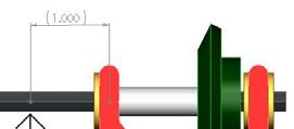
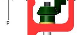
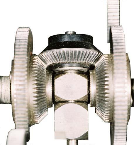
7 Initial leadscrew shape Net shapes after assembly Initial linear bearing shape Leadscrews: Mounting Leadscrews used in robotics contests are often mounted using a radial sleeve bearing at one end, and journal and thrust bearings at the other end The bearings in gear motors are generally not designed to take the huge thrust loads that a leadscrew can generate Beware of constraints: either provide precision or compliance The only way to effectively mount a leadscrew to achieve a zero-slope end condition for maximum buckling resistance is to use a back-to-back arrangement of ball bearings This also generally involves the use of a ballscrew and is not used in simple.007 machines It is easy to make a leadscrew Screw threads can be cut directly into round, square, or hexagonal steel stock A square or hexagonal hole can be broached into a gear or pulley which can then be pressed onto the leadscrew 000 Alexander Slocum 6-7


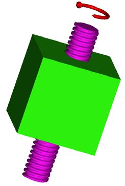
8 Leadscrews: Differential Motion Differential motion can be used to create most excellent motions: Two independently rotating leadscrew nuts on a common screw shaft can enable components to move in the same or different directions simultaneously See US patent 6,194,859 X-Y positioner based on X axis motions A leadscrew with left and right hand threads can simultaneously move components together or apart See US patent 4,765,668 " Double End Effector A leadscrew with two different leads can create an incredibly small virtual lead Alex Slocum s first miniature 6 axis robot and double gripper! How do you get the screw in?! 000 Alexander Slocum 6-8
9 Leadscrews: Flexibility Leadscrews are used in many everyday applications How does a CD drive work? Must the pitch of a leadscrew be constant? See Expanding Gripper with Elastically Variable Pitch Screw, #5,839,769, Nov. 4, 1998 To reduce friction, could the gripper units threads be replaced with inclined rollers at different angles to achieve different effective leads? (I bet they could!) 000 Alexander Slocum 6-9


 0 Thrust bearing diameter, dthrust (mm) 5 Thread angle (deg), alpha (rad) 30 0.")
 591 Torque required at thrust bearing (N-mm) 500 Total torque (N-mm) 1,091 Backdriveable?")
10 d D c α e L piston Leadscrews: Contest Machine Design Example β A How might we evolve a lifting strategy into a boom concept? What are the forces on the boom and where are they applied? What are its ranges of motion? How fast should it move the load? What is the desired resolution of motion? Use Matlab or a spreadsheet to study the effects of different design parameters? Ayr Muir-Harmony s awesome.007 machine! Leadscrew! R 000 Alexander Slocum 6-10 Y γ f φ X a B b L boom θ x F, y F F y F x M leadscrew_design.xls Screwthread forces Enter numbers in BOLD, output in RED Written by Alex Slocum, last updated 1/17/03 Force (no help from gravity), thrust (N) 400 Lead, (mm) Coefficient of friction, mu 0.1 Screw pitch diameter, dscrew (mm) 0 Thrust bearing diameter, dthrust (mm) 5 Thread angle (deg), alpha (rad) Thread root stress concentration, scf 1.5 Beta 0.1 Torque required at screw (N-mm) 591 Torque required at thrust bearing (N-mm) 500 Total torque (N-mm) 1,091 Backdriveable? NO Thread efficiency, et % Total system efficiency 1% Estimated torsional stress (N/mm^) 0.5 Tensile stress (N/mm^) 1.57 Mises equivelant stress (N/mm^).71 Gearbox ratio 1 Travel (mm) 50 Time to travel (s) 5 Motor speed (rpm, rad/s) Gearbox efficiency 90% Motor torque (N-mm) 113 Power (watts) 38
CHAPTER 8 SCREWS, FASTENERS, NONPERMANENT JOINTS
 CHAPTER 8 SCREWS, FASTENERS, NONPERMANENT JOINTS This chapter deals with the design and analysis of nonpermanent fasteners such as bolts, power screws, cap screws, setscrews, eys and pins. 8- Standards
MEMS Project 2 Assignment. Design of a Shaft to Transmit Torque Between Two Pulleys
 MEMS 029 Project 2 Assignment Design of a Shaft to Transmit Torque Between Two Pulleys Date: February 5, 206 Instructor: Dr. Stephen Ludwick Product Definition Shafts are incredibly important in order
CHAPTER 17 FLEXIBLE MECHANICAL ELEMENTS LECTURE NOTES DR. HAFTIRMAN
 CHAPTER 17 LEXIBLE MECHANICAL ELEMENTS LECTURE NOTES DR. HATIRMAN lexible Mechanical Elements Belts Roller chains Wire rope lexible shafts lexible Mechanical Elements Belts, ropes, chains, and other similar
SOLUTION (17.3) Known: A simply supported steel shaft is connected to an electric motor with a flexible coupling.
 Known: A simply supported steel shaft is connected to an electric motor with a flexible coupling.") SOLUTION (17.3) Known: A simply supported steel shaft is connected to an electric motor with a flexible coupling. Find: Determine the value of the critical speed of rotation for the shaft. Schematic and
SOLUTION (17.3) Known: A simply supported steel shaft is connected to an electric motor with a flexible coupling. Find: Determine the value of the critical speed of rotation for the shaft. Schematic and
Arberi Ferraj. Wentworth Institute of Technology. Design of Machine Elements MECH 420
 P a g e 1 Arberi Ferraj Wentworth Institute of Technology Design of Machine Elements MECH 420 P a g e 2 1. Executive Summary A scissor car jack was designed and must be reverse-engineered in order to discover
Matlab Sheet 2. Arrays
 Matlab Sheet 2 Arrays 1. a. Create the vector x having 50 logarithmically spaced values starting at 10 and ending at 1000. b. Create the vector x having 20 logarithmically spaced values starting at 10
Precision Ball Screw/Spline
 58-2E Models BNS-A, BNS, NS-A and NS Seal Outer ring Shim plate Seal Spline nut Seal Collar Shim plate Seal End cap Ball Outer ring Ball screw nut Outer ring Ball Retainer Retainer Outer ring Point of
2014 MECHANICS OF MATERIALS
 R10 SET - 1 II. Tech I Semester Regular Examinations, March 2014 MEHNIS OF MTERILS (ivil Engineering) Time: 3 hours Max. Marks: 75 nswer any FIVE Questions ll Questions carry Equal Marks ~~~~~~~~~~~~~~~~~~~~~~~~~
Revision Term 2. Prof Ahmed Kovacevic
 ME 1110 Engineering Practice 1 Engineering Drawing and Design - Lecture 20 Revision Term 2 Prof Ahmed Kovacevic School of Engineering and Mathematical Sciences Room CG25, Phone: 8780, E-Mail: a.kovacevic@city.ac.uk
Stress Analysis Lecture 3 ME 276 Spring Dr./ Ahmed Mohamed Nagib Elmekawy
 Stress Analysis Lecture 3 ME 276 Spring 2017-2018 Dr./ Ahmed Mohamed Nagib Elmekawy Axial Stress 2 Beam under the action of two tensile forces 3 Beam under the action of two tensile forces 4 Shear Stress
Experiment Two (2) Torsional testing of Circular Shafts
 Torsional testing of Circular Shafts") Experiment Two (2) Torsional testing of Circular Shafts Introduction: Torsion occurs when any shaft is subjected to a torque. This is true whether the shaft is rotating (such as drive shafts on engines,
Experiment Two (2) Torsional testing of Circular Shafts Introduction: Torsion occurs when any shaft is subjected to a torque. This is true whether the shaft is rotating (such as drive shafts on engines,
ENT345 Mechanical Components Design
 1) LOAD AND STRESS ANALYSIS i. Principle stress ii. The maximum shear stress iii. The endurance strength of shaft. 1) Problem 3-71 A countershaft carrying two-v belt pulleys is shown in the figure. Pulley
Mechanical Design. Design of Shaft
 Mechanical Design Design of Shaft Outline Practical information Shaft design Definition of shaft? It is a rotating member, in general, has a circular cross-section and is used to transmit power. The shaft
MECHANICS OF MATERIALS. Prepared by Engr. John Paul Timola
 MECHANICS OF MATERIALS Prepared by Engr. John Paul Timola Mechanics of materials branch of mechanics that studies the internal effects of stress and strain in a solid body. stress is associated with the
Product description. Compact Modules. Characteristic features. Further highlights
 4 Compact Modules Product description Characteristic features Five fine-tuned sizes based on a compact precision aluminum profile with two integrated pre-tensioned ball rail systems Identical external
Improvement in the Design & Manufacturing of Twin Worm Self Locking Technique and applications
 Improvement in the Design & Manufacturing of Twin Worm Self Locking Technique and applications Prof. P.B. Kadam 1, Prof. M.R. Todkar 2 1 Assistant Professor, Mechanical Engineering Department, T.K.I.E.T.Warananagar,
Dimensions of propulsion shafts and their permissible torsional vibration stresses
 (Feb 2005) (orr.1 Mar 2012) (orr.2 Nov 2012) Dimensions of propulsion shafts and their permissible torsional vibration stresses.1 Scope This UR applies to propulsion shafts such as intermediate and propeller
SECOND ENGINEER REG. III/2 APPLIED MECHANICS
 SECOND ENGINEER REG. III/2 APPLIED MECHANICS LIST OF TOPICS Static s Friction Kinematics Dynamics Machines Strength of Materials Hydrostatics Hydrodynamics A STATICS 1 Solves problems involving forces
D : SOLID MECHANICS. Q. 1 Q. 9 carry one mark each.
 GTE 2016 Q. 1 Q. 9 carry one mark each. D : SOLID MECHNICS Q.1 single degree of freedom vibrating system has mass of 5 kg, stiffness of 500 N/m and damping coefficient of 100 N-s/m. To make the system
Engineering Mechanics: Statics
 Engineering Mechanics: Statics Chapter 6B: Applications of Friction in Machines Wedges Used to produce small position adjustments of a body or to apply large forces When sliding is impending, the resultant
Linear guide drives. Synchronous shafts The use of synchronous shafts enables several linear axes to be operated with one drive.
 Linear guide drives Drive concept The linear guides are driven via the hollow shaft in the drive head. The drive head is used to directly install a motor or alternatively (in connection with a center shaft)
STATICS. Friction VECTOR MECHANICS FOR ENGINEERS: Eighth Edition CHAPTER. Ferdinand P. Beer E. Russell Johnston, Jr.
 Eighth E 8 Friction CHAPTER VECTOR MECHANICS FOR ENGINEERS: STATICS Ferdinand P. Beer E. Russell Johnston, Jr. Lecture Notes: J. Walt Oler Texas Tech University Contents Introduction Laws of Dry Friction.
Flywheels-Function need and Operation
 STUDY OF FLYWHEEL Flywheel definition A flywheel is an inertial energy-storage device. It absorbs mechanical energy and serves as a reservoir, storing energy during the period when the supply of energy
Determine the resultant internal loadings acting on the cross section at C of the beam shown in Fig. 1 4a.
 E X M P L E 1.1 Determine the resultant internal loadings acting on the cross section at of the beam shown in Fig. 1 a. 70 N/m m 6 m Fig. 1 Support Reactions. This problem can be solved in the most direct
APPENDIX. SELECTING THE SureServo SERVO SYSTEM. In This Appendix... Selecting the SureServo Servo System...B 2. Leadscrew - Example Calculations...
 SELECTING THE SureServo SERVO SYSTEM APPENDIX B In This Appendix... Selecting the SureServo Servo System............B 2 The Selection Procedure......................................B 2 How many pulses
Chapter 3. Inertia. Force. Free Body Diagram. Net Force. Mass. quantity of matter composing a body represented by m. units are kg
 Chapter 3 Mass quantity of matter composing a body represented by m Kinetic Concepts for Analyzing Human Motion units are kg Inertia tendency to resist change in state of motion proportional to mass has
Controlling Thermal Expansion
 Controlling Thermal Expansion Strategies for Maximizing the Repeatability of your Linear Stage By David Goosen, Mechanical Engineering Team INTRODUCTION Most of us are aware that all common engineering
Selecting the SureStep Stepping System...C 2
 SELECTING THE SureStep STEPPING SYSTEM APPENDIX C In This Appendix... Selecting the SureStep Stepping System.............C 2 The Selection Procedure..............................C 2 How many pulses from
OUTCOME 1 MECHANICAL POWER TRANSMISSION SYSTEMS TUTORIAL 2 SCREW DRIVES. On completion of this short tutorial you should be able to do the following.
 Unit 60: Dynamics of Machines Unit code: H/601/1411 QCF Level:4 Credit value:15 OUTCOME 1 MECHANICAL POWER TRANSMISSION SYSTEMS TUTORIAL 2 SCREW DRIVES 1. Be able to determine the kinetic and dynamic parameters
Design and Analysis of Adjustable Inside Diameter Mandrel for Induction Pipe Bender
 International Journal of Engineering Trends and Technology (IJETT) Volume0Number - Apr 0 Design and Analysis of Adjustable Inside Diameter Mandrel for Induction Pipe Bender S.Nantha Gopan, M.Gowtham J.Kirubakaran
6) Motors and Encoders
 Motors and Encoders") 6) Motors and Encoders Electric motors are by far the most common component to supply mechanical input to a linear motion system. Stepper motors and servo motors are the popular choices in linear motion
6) Motors and Encoders Electric motors are by far the most common component to supply mechanical input to a linear motion system. Stepper motors and servo motors are the popular choices in linear motion
Overview. Dry Friction Wedges Flatbelts Screws Bearings Rolling Resistance
 Friction Chapter 8 Overview Dry Friction Wedges Flatbelts Screws Bearings Rolling Resistance Dry Friction Friction is defined as a force of resistance acting on a body which prevents slipping of the body
Engineering Mechanics: Statics
 Engineering Mechanics: Statics Chapter 6B: Applications of Friction in Machines Wedges Used to produce small position adjustments of a body or to apply large forces When sliding is impending, the resultant
On completion of this short tutorial you should be able to do the following. Calculate the effort and torque needed to raise and lower a load.
 CITY AND GUILDS 9210 Unit 130 MECHANICS OF MACHINES AND STRENGTH OF MATERIALS OUTCOME 6 TUTORIAL 3 - SCREW DRIVES Outcome 6 Explain the concepts of friction and friction devices. The learner can: 1. Explain
MECTROL CORPORATION 9 NORTHWESTERN DRIVE, SALEM, NH PHONE FAX TIMING BELT THEORY
 MECTRO CORPORATION 9 NORTHWESTERN DRIVE, SAEM, NH 03079 PHONE 603-890-55 FAX 603-890-66 TIMING BET THEORY Copyright 997, 999, 00 Mectrol Corporation. All rights reserved. April 00 Timing Belt Theory Introduction
Design and development of multi-utility zero slip gripper system by application of mating worm system
 ISSN 2395-1621 Design and development of multi-utility zero slip gripper system by application of mating worm system #1 Pooja D. Shintre, #2 Sambhaji S. Gaikwad #1 Mechanical Design, Sinhgad Institute
WORCESTER POLYTECHNIC INSTITUTE
 WORCESTER POLYTECHNIC INSTITUTE MECHANICAL ENGINEERING DEPARTMENT STRESS ANALYSIS ES-2502, C 2012 Lecture 17: 10 February 2012 General information Instructor: Cosme Furlong HL-151 (508) 831-5126 cfurlong@wpi.edu
CLUTCHES AND BRAKES. Square-jaw clutch
 Clutches: CLUTCHES AND BRAKES A Clutch is a mechanical device which is used to connect or disconnect the source of power from the remaining parts so the power transmission system at the will of the operator.
CIVL222 STRENGTH OF MATERIALS. Chapter 6. Torsion
 CIVL222 STRENGTH OF MATERIALS Chapter 6 Torsion Definition Torque is a moment that tends to twist a member about its longitudinal axis. Slender members subjected to a twisting load are said to be in torsion.
Dynamic Tests on Ring Shear Apparatus
 , July 1-3, 2015, London, U.K. Dynamic Tests on Ring Shear Apparatus G. Di Massa Member IAENG, S. Pagano, M. Ramondini Abstract Ring shear apparatus are used to determine the ultimate shear strength of
Science 7 Unit B: Structures and Forces. Topic 4. Forces, Loads, & Stresses. pp WORKBOOK. Name:
 Science 7 Unit B: Structures and Forces Topic 4 Forces, Loads, & Stresses pp. 305-314 WORKBOOK Name: Every object that provides support is a structure. A structure may be made up of one or more parts,
Servo Motor Selection Flow Chart
 Servo otor Selection Flow Chart START Selection Has the machine Been Selected? YES NO Explanation etermine the size, mass, coefficient of References friction, and external forces of all the moving part
1 of 12. Given: Law of Cosines: C. Law of Sines: Stress = E = G
 ES230 STRENGTH OF MATERIALS FINAL EXAM: WEDNESDAY, MAY 15 TH, 4PM TO 7PM, AEC200 Closed book. Calculator and writing supplies allowed. Protractor and compass required. 180 Minute Time Limit You must have
1 of 12. Law of Sines: Stress = E = G. Deformation due to Temperature: Δ
 NAME: ES30 STRENGTH OF MATERIALS FINAL EXAM: FRIDAY, MAY 1 TH 4PM TO 7PM Closed book. Calculator and writing supplies allowed. Protractor and compass allowed. 180 Minute Time Limit GIVEN FORMULAE: Law
International Journal of Modern Trends in Engineering and Research e-issn No.: , Date: 2-4 July, 2015
 International Journal of Modern Trends in Engineering and Research www.ijmter.com e-issn No.:2349-9745, Date: 2-4 July, 2015 Design And Analysis Of Lead Screw For Fixture Aman B. kotwal 1,Mangesh N. Gavhane
1 of 7. Law of Sines: Stress = E = G. Deformation due to Temperature: Δ
 NME: ES30 STRENGTH OF MTERILS FINL EXM: FRIDY, MY 1 TH 4PM TO 7PM Closed book. Calculator and writing supplies allowed. Protractor and compass allowed. 180 Minute Time Limit GIVEN FORMULE: Law of Cosines:
AE 688 Dynamics And Vibration Assignment No. 2. with the brakes slightly applied so that the speed v is constant. The slope decreases abruptly to θ
 AE 688 Dynamics And Vibration Assignment No. 1. A car is descending the hill of slope θ 1 with the brakes slightly applied so that the speed v is constant. The slope decreases abruptly to θ at point A.
UNIT 3 Friction and Belt Drives 06ME54. Structure
 UNIT 3 Friction and Belt Drives 06ME54 Structure Definitions Types of Friction Laws of friction Friction in Pivot and Collar Bearings Belt Drives Flat Belt Drives Ratio of Belt Tensions Centrifugal Tension
1. What would be the value of F1 to balance the system if F2=20N? 20cm T =? 20kg
 1. What would be the value of F1 to balance the system if F2=20N? F2 5cm 20cm F1 (a) 3 N (b) 5 N (c) 4N (d) None of the above 2. The stress in a wire of diameter 2 mm, if a load of 100 gram is applied
Tuesday, February 11, Chapter 3. Load and Stress Analysis. Dr. Mohammad Suliman Abuhaiba, PE
 1 Chapter 3 Load and Stress Analysis 2 Chapter Outline Equilibrium & Free-Body Diagrams Shear Force and Bending Moments in Beams Singularity Functions Stress Cartesian Stress Components Mohr s Circle for
Training III. Force Generation and Transmission. Team 2228 CougarTech 1
 Training III Force Generation and Transmission Team 2228 CougarTech 1 Team 2228 CougarTech 2 Force Generation and Transmission Objectives Understand Energy Conversion to do Work on Robots Understand mechanical
4. SHAFTS. A shaft is an element used to transmit power and torque, and it can support
 4. SHAFTS A shaft is an element used to transmit power and torque, and it can support reverse bending (fatigue). Most shafts have circular cross sections, either solid or tubular. The difference between
Automobile manual transmission
 Design of Shaft A shaft is a rotating member usually of circular crosssection (soli or hollow), which is use to transmit power an rotational motion. Axles are non rotating member. Elements such as gears,
An investigation into the relative accuracy of ball-screws and linear encoders over a broad range of application configurations and usage conditions
 An investigation into the relative accuracy of ball-screws and linear encoders over a broad range of application configurations and usage conditions A.J. White, S.R. Postlethwaite, D.G. Ford Precision
 Selection of jack size No. 5 Check again with ball screw jack Type J-B. Yes. Set the hand wheel radius if the screw jack is to be used for manual operation. Yes. Yes. Specification Select temporarily the
MECHANICS OF MATERIALS
 2009 The McGraw-Hill Companies, Inc. All rights reserved. Fifth SI Edition CHAPTER 3 MECHANICS OF MATERIALS Ferdinand P. Beer E. Russell Johnston, Jr. John T. DeWolf David F. Mazurek Torsion Lecture Notes:
High Tech High Top Hat Technicians. An Introduction to Solid Mechanics. Is that supposed to bend there?
 High Tech High Top Hat Technicians An Introduction to Solid Mechanics Or Is that supposed to bend there? Why don't we fall through the floor? The power of any Spring is in the same proportion with the
Failure from static loading
 Failure from static loading Topics Quiz /1/07 Failures from static loading Reading Chapter 5 Homework HW 3 due /1 HW 4 due /8 What is Failure? Failure any change in a machine part which makes it unable
NAME: Given Formulae: Law of Cosines: Law of Sines:
 NME: Given Formulae: Law of Cosines: EXM 3 PST PROBLEMS (LESSONS 21 TO 28) 100 points Thursday, November 16, 2017, 7pm to 9:30, Room 200 You are allowed to use a calculator and drawing equipment, only.
Members Subjected to Combined Loads
 Members Subjected to Combined Loads Combined Bending & Twisting : In some applications the shaft are simultaneously subjected to bending moment M and Torque T.The Bending moment comes on the shaft due
Chapter 7: Stepper Motors. (Revision 6.0, 27/10/2014)
") Chapter 7 Stepper Motors (Revision 6.0, 7/10/014) 1. Stepping Angle Analysis The following analysis derives the formula for the stepping angle of the stepper motor. It has been reproduced and edited from
Chapter 7 Stepper Motors (Revision 6.0, 7/10/014) 1. Stepping Angle Analysis The following analysis derives the formula for the stepping angle of the stepper motor. It has been reproduced and edited from
EDEXCEL NATIONAL CERTIFICATE/DIPLOMA FURTHER MECHANICAL PRINCIPLES AND APPLICATIONS UNIT 11 - NQF LEVEL 3 OUTCOME 4 - LIFTING MACHINES
 EDEXCEL NATIONAL CERTIFICATE/DIPLOMA FURTHER MECHANICAL PRINCIPLES AND APPLICATIONS UNIT 11 - NQF LEVEL 3 OUTCOME 4 - LIFTING MACHINES CONTENT Be able to determine the operating characteristics of lifting
PES Institute of Technology
 PES Institute of Technology Bangalore south campus, Bangalore-5460100 Department of Mechanical Engineering Faculty name : Madhu M Date: 29/06/2012 SEM : 3 rd A SEC Subject : MECHANICS OF MATERIALS Subject
Dynamics Plane kinematics of rigid bodies Section 4: TJW Rotation: Example 1
 Section 4: TJW Rotation: Example 1 The pinion A of the hoist motor drives gear B, which is attached to the hoisting drum. The load L is lifted from its rest position and acquires an upward velocity of
Product Description. Further highlights. Outstanding features. 4 Bosch Rexroth Corporation Miniature Linear Modules R310A 2418 (2009.
 4 Bosch Rexroth orporation Miniature Linear Modules R310A 2418 (2009.05) Product Description Outstanding features Rexroth Miniature Linear Modules are precise, ready-to-install linear motion systems that
Chapter 8 Structural Design and Analysis. Strength and stiffness 5 types of load: Tension Compression Shear Bending Torsion
 Chapter 8 Structural Design and Analysis 1 Strength and stiffness 5 types of load: Tension Compression Shear Bending Torsion Normal Stress Stress is a state when a material is loaded. For normal forces
Static Failure (pg 206)
") Static Failure (pg 06) All material followed Hookeʹs law which states that strain is proportional to stress applied, until it exceed the proportional limits. It will reach and exceed the elastic limit
Static Failure (pg 06) All material followed Hookeʹs law which states that strain is proportional to stress applied, until it exceed the proportional limits. It will reach and exceed the elastic limit
Note: Read section (12-1) objective of this chapter (Page 532)
 objective of this chapter (Page 532)") References: Machine Elements in Mechanical Design by Robert L. Mott, P.E. (Chapter 12 Note: Read section (12-1 objective of this chapter (Page 532 Page 1 of 29 Shaft Design Procedure (Sec. 12-2, Page 532
References: Machine Elements in Mechanical Design by Robert L. Mott, P.E. (Chapter 12 Note: Read section (12-1 objective of this chapter (Page 532 Page 1 of 29 Shaft Design Procedure (Sec. 12-2, Page 532
5. Repeated Loading. 330:148 (g) Machine Design. Dynamic Strength. Dynamic Loads. Dynamic Strength. Dynamic Strength. Nageswara Rao Posinasetti
 Machine Design. Dynamic Strength. Dynamic Loads. Dynamic Strength. Dynamic Strength. Nageswara Rao Posinasetti") 330:48 (g) achine Design Nageswara Rao Posinasetti P N Rao 5. Repeated Loading Objectives Identify the various kinds of loading encountered on a part and learn to combine them as appropriate. Determine
330:48 (g) achine Design Nageswara Rao Posinasetti P N Rao 5. Repeated Loading Objectives Identify the various kinds of loading encountered on a part and learn to combine them as appropriate. Determine
WORCESTER POLYTECHNIC INSTITUTE
 WORCESTER POLYTECHNIC INSTITUTE MECHANICAL ENGINEERING DEPARTMENT STRESS ANALYSIS ES-2502, C 2012 Lecture 03: Stress 17 January 2012 General information Instructor: Cosme Furlong HL-151 (508) 831-5126
Design of Mechanical Drives for a Parabolic Radio Antenna
 Design of Mechanical Drives for a Parabolic Radio Antenna Akshaya Kulkarni 1, Kunal Bhandari 1, Pranoti Panchwagh 1 Department of Mechanical Engineering,VIIT, Savitribai Phule Pune University, Ganeshkhind,
Mechanical Engineering Ph.D. Preliminary Qualifying Examination Solid Mechanics February 25, 2002
 student personal identification (ID) number on each sheet. Do not write your name on any sheet. #1. A homogeneous, isotropic, linear elastic bar has rectangular cross sectional area A, modulus of elasticity
Objectives. Power in Translational Systems 298 CHAPTER 6 POWER
 Objectives Explain the relationship between power and work. Explain the relationship between power, force, and speed for an object in translational motion. Calculate a device s efficiency in terms of the
Development of the Screw-driven Motors by Stacked Piezoelectric Actuators
 Proceedings of the 4th IIAE International Conference on Industrial Application Engineering 2016 Development of the Screw-driven Motors by Stacked Piezoelectric Actuators Shine-Tzong Ho a,*, Hao-Wei Chen
Eng Sample Test 4
 1. An adjustable tow bar connecting the tractor unit H with the landing gear J of a large aircraft is shown in the figure. Adjusting the height of the hook F at the end of the tow bar is accomplished by
Dynamics of Machinery
 Dynamics of Machinery Two Mark Questions & Answers Varun B Page 1 Force Analysis 1. Define inertia force. Inertia force is an imaginary force, which when acts upon a rigid body, brings it to an equilibrium
ANALYSIS OF GATE 2018*(Memory Based) Mechanical Engineering
 Mechanical Engineering") ANALYSIS OF GATE 2018*(Memory Based) Mechanical Engineering 6% 15% 13% 3% 8% Engineering Mathematics Engineering Mechanics Mechanics of Materials Theory Of Machines Machine Design Fluid Mechanics 19% 8%
ANALYSIS OF GATE 2018*(Memory Based) Mechanical Engineering 6% 15% 13% 3% 8% Engineering Mathematics Engineering Mechanics Mechanics of Materials Theory Of Machines Machine Design Fluid Mechanics 19% 8%
Engineering Mechanics
 Engineering Mechanics Continued (5) Mohammed Ameen, Ph.D Professor of Civil Engineering B Section Forces in Beams Beams are thin prismatic members that are loaded transversely. Shear Force, Aial Force
ROLLER BEARING FAILURES IN REDUCTION GEAR CAUSED BY INADEQUATE DAMPING BY ELASTIC COUPLINGS FOR LOW ORDER EXCITATIONS
 ROLLER BEARIG FAILURES I REDUCTIO GEAR CAUSED BY IADEQUATE DAMPIG BY ELASTIC COUPLIGS FOR LOW ORDER EXCITATIOS ~by Herbert Roeser, Trans Marine Propulsion Systems, Inc. Seattle Flexible couplings provide
Ball Reverser. Ball Reverser Actuator. FLENNOR Power Transmission Products. Patented
 Ball Reverser FLENNOR Power Transmission Products Ball Reverser Actuator Patented Ball Reverser Principle General Information NORCO'S Ball Reverser Actuator is a unique actuator which provides automatic
Example of Calculating the Nominal Life
 Condition (Horizontal Installation) Assumed model number : KR 5520A LM Guide unit (C = 800N, C 0 = 6900N) Ball Screw unit (C a = 620N, C 0a = 9290N) Bearing unit(fixed Side) (C a = 7600N, P 0a = 990N)
Sliding Bearings. Fig.(1) (a) Full-journal bearing and (b) partial-journal bearing
 (a) Full-journal bearing and (b) partial-journal bearing") Sliding Bearings The goal of a bearing is to provide relative positioning and rotational freedom while transmitting a load between two parts, commonly a shaft and its housing. The object of lubrication
Sliding Bearings The goal of a bearing is to provide relative positioning and rotational freedom while transmitting a load between two parts, commonly a shaft and its housing. The object of lubrication
Hilti HSV-F Stud anchor
 Product Data Sheet Hilti Anchor version Benefits torque-controlled mechanical expansion allows immediate load application HSV-F Carbon steel, hot dipped galvanised, min 42 microns coating thickness setting
Mechanisms Simple Machines. Lever, Wheel and Axle, & Pulley
 Mechanisms Simple Machines Lever, Wheel and Axle, & Pulley Simple Machines Mechanisms that manipulate magnitude of force and distance. The Six Simple Machines Lever Wheel and Axle Pulley The Six Simple
Stress Transformation Equations: u = +135 (Fig. a) s x = 80 MPa s y = 0 t xy = 45 MPa. we obtain, cos u + t xy sin 2u. s x = s x + s y.
 s x = 80 MPa s y = 0 t xy = 45 MPa. we obtain, cos u + t xy sin 2u. s x = s x + s y.") 014 Pearson Education, Inc., Upper Saddle River, NJ. All rights reserved. This material is protected under all copyright laws as they currently 9 7. Determine the normal stress and shear stress acting
014 Pearson Education, Inc., Upper Saddle River, NJ. All rights reserved. This material is protected under all copyright laws as they currently 9 7. Determine the normal stress and shear stress acting
Shafts Introduction. Shafts 509
 Shafts 509 C H A P T E R 14 Shafts 1. Introduction.. Material Used for Shafts.. Manufacturing of Shafts. 4. Types of Shafts. 5. Standard Sizes of Transmission Shafts. 6. Stresses in Shafts. 7. Maximum
The Rotation Stabilizer Used For A Gravity. Detector With MAB25 Encoder In DRIACS-G2 System
 The Rotation Stabilizer Used For A Gravity Detector With MAB25 Encoder In DRIACS-G2 System JH1KRC Mike Watanabe, JA6XED Hisao Tsukamoto 2012 International EME Conference, Cambridge, U. K. Abstract To detect
Flexible Mechanical Elements
 lexible Mechanical Elements INTRODUCTION Belts, ropes, chains, and other similar elastic or flexible machine elements are used in conveying systems and in the transmission of power over comparatively long
R-Plus System Frontespizio_R_PlusSystem.indd 1 11/06/ :32:02
 R-Plus System R-Plus System R-Plus system R-Plus system description Fig. R-Plus system R-Plus System is Rollon s series of rack & pinion driven actuators. Rollon R-Plus System series linear units are designed
Members Subjected to Torsional Loads
 Members Subjected to Torsional Loads Torsion of circular shafts Definition of Torsion: Consider a shaft rigidly clamped at one end and twisted at the other end by a torque T = F.d applied in a plane perpendicular
EMA 3702 Mechanics & Materials Science (Mechanics of Materials) Chapter 3 Torsion
 Chapter 3 Torsion") EMA 3702 Mechanics & Materials Science (Mechanics of Materials) Chapter 3 Torsion Introduction Stress and strain in components subjected to torque T Circular Cross-section shape Material Shaft design Non-circular
EMA 3702 Mechanics & Materials Science (Mechanics of Materials) Chapter 3 Torsion Introduction Stress and strain in components subjected to torque T Circular Cross-section shape Material Shaft design Non-circular
WORK SHEET FOR MEP311
 EXPERIMENT II-1A STUDY OF PRESSURE DISTRIBUTIONS IN LUBRICATING OIL FILMS USING MICHELL TILTING PAD APPARATUS OBJECTIVE To study generation of pressure profile along and across the thick fluid film (converging,
PERIYAR CENTENARY POLYTECHNIC COLLEGE PERIYAR NAGAR - VALLAM THANJAVUR. DEPARTMENT OF MECHANICAL ENGINEERING QUESTION BANK
 PERIYAR CENTENARY POLYTECHNIC COLLEGE PERIYAR NAGAR - VALLAM - 613 403 - THANJAVUR. DEPARTMENT OF MECHANICAL ENGINEERING QUESTION BANK Sub : Strength of Materials Year / Sem: II / III Sub Code : MEB 310
: APPLIED MECHANICS & STRENGTH OF MATERIALS COURSE CODE : 4021 COURSE CATEGORY : A PERIODS/ WEEK : 5 PERIODS/ SEMESTER : 75 CREDIT : 5 TIME SCHEDULE
 COURSE TITLE : APPLIED MECHANICS & STRENGTH OF MATERIALS COURSE CODE : 4021 COURSE CATEGORY : A PERIODS/ WEEK : 5 PERIODS/ SEMESTER : 75 CREDIT : 5 TIME SCHEDULE MODULE TOPIC PERIODS 1 Simple stresses
Simple Machines. Changes effort, displacement or direction and magnitude of a load 6 simple machines. Mechanical Advantage
 Simple Machine Simple Machines Changes effort, displacement or direction and magnitude of a load 6 simple machines Lever Incline plane Wedge Screw Pulley Wheel and Axle Mechanical Advantage Ideal: IMA
Chapter 5 Torsion STRUCTURAL MECHANICS: CE203. Notes are based on Mechanics of Materials: by R. C. Hibbeler, 7th Edition, Pearson
 STRUCTURAL MECHANICS: CE203 Chapter 5 Torsion Notes are based on Mechanics of Materials: by R. C. Hibbeler, 7th Edition, Pearson Dr B. Achour & Dr Eng. K. El-kashif Civil Engineering Department, University
2. Rigid bar ABC supports a weight of W = 50 kn. Bar ABC is pinned at A and supported at B by rod (1). What is the axial force in rod (1)?
. What is the axial force in rod (1)?") IDE 110 S08 Test 1 Name: 1. Determine the internal axial forces in segments (1), (2) and (3). (a) N 1 = kn (b) N 2 = kn (c) N 3 = kn 2. Rigid bar ABC supports a weight of W = 50 kn. Bar ABC is pinned at
IDE 110 S08 Test 1 Name: 1. Determine the internal axial forces in segments (1), (2) and (3). (a) N 1 = kn (b) N 2 = kn (c) N 3 = kn 2. Rigid bar ABC supports a weight of W = 50 kn. Bar ABC is pinned at
Levers. 558 A Textbook of Machine Design
 558 A Textbook of Machine Design C H A P T E R 15 Levers 1. Introduction.. Application of Levers in Engineering Practice.. Design of a Lever. 4. Hand Lever. 5. Foot Lever. 6. Cranked Lever. 7. Lever for
FINAL EXAM CLOSED BOOK
 Physics 7A- Section 2, Fall 2008. Instructor Lanzara FINAL EXAM CLOSED BOOK GOOD LUCK! Print Name Discussion Section# or Time Signature Discussion Section GSI Student ID# Problem Points Score 1 20 2 20
The principle of the flywheel is found before the many centuries ago in spindle and the potter's wheel.
 TOM Fly Wheel Mechanical Engineering Department The principle of the flywheel is found before the many centuries ago in spindle and the potter's wheel. A heavy-rimmed rotating wheel used to minimize variations