500 Delaware Ave. APPENDICES
|
|
|
- Silas Stephens
- 5 years ago
- Views:
Transcription
1 APPENDICES i
2 APPENDICES APPENDIX A: LOAD CALCULATIONS... iii A.1 Snow Loading...iv A.2 Lateral Loading...vi A.2.1 Wind... vi A.2.2 Seismic...xi APPENDIX B: PRELIMINARY MEMBER DESIGN... xiii B.1 Post-tensioned Slab...xiv B.2 Columns...xvi B.3 Beams...xix B.4 Shearwalls...xxi APPENDIX C: PLANS... xxii C.1 Composite Steel-Foundation... xxiii C.2 Composite Steel-Typical Floor...xxiv C.3 Post-tensioned Concrete-Foundation...xxv C.4 Post-tensioned Concrete-Floor Framing...xxvi C.5 Post-tensioned Concrete-Reinforcement... xxviii APPENDIX D: BREADTH STUDIES... xxxii D.1 Mechanical Studies... xxxiii D.2 Construction Studies...xxxiv D.2.1 Material Takeoffs...xxxiv D.2.2 Estimates... xxxv D.2.3 Schedule...xxxvii ii
3 APPENDIX A: LOAD CALCULATIONS iii

4 A.1 Snow Loading Design Parameters P g psf Ground Snow Load - Figure Above Tree Line Terrain Category - Section Fully Exposed Roof Exposure - Table b C e 0.8 Exposure Factor - Table C t 1.00 Thermal Factor - Section I Importance Category - Table I 1.0 Importance Factor - Table P f psf Flat Roof Snow Load, Pf = 0.7 * Ce * Ct * Is * Pg - Section D 17 pcf Snow density,d = 0.13Pg +14 <= 30 pcf h b 1' Height of minimum roof snow load, (Default, Pf/D) h r 19' Difference in height between upper and lower roofs h c 17' Difference in height between upper roof and top of flat roof snow l u, high 36' Horizontal dimension of upper roof normal to the line of change of roof level l u, low 48' Horizontal dimension of lower roof normal to the line of change of roof level Drift Calculations Drift location Calc. h d (ft) Corrected h d (ft) P d (psf) P max (psf) W d Windward Drift Leeward Drift Design Drift X Y A1 (psf) A2 (psf) Total (psf) iv
5 Design Parameters P g psf Ground Snow Load - Figure Above Tree Line Terrain Category - Section Fully Exposed Roof Exposure - Table b C e 0.7 Exposure Factor - Table C t 1.00 Thermal Factor - Section I Importance Category - Table I 1.0 Importance Factor - Table P f psf Flat Roof Snow Load, Pf = 0.7 * Ce * Ct * Is * Pg - Section D pcf Snow density,d = 0.13Pg +14 <= 30 pcf h b 1.16' Height of minimum roof snow load, (Default, Pf/D) h r 18.5' Difference in height between upper and lower roofs h c 17.3' Difference in height between upper roof and top of flat roof snow l u, high 44' Horizontal dimension of upper roof normal to the line of change of roof level l u, low 130' Horizontal dimension of lower roof normal to the line of change of roof level Drift Calculations Drift location Calc. h d (ft) Corrected h d (ft) P d (psf) P max (psf) W d Windward Drift Leeward Drift Design Drift X Y A1 (psf) A2 (psf) Total (psf) v

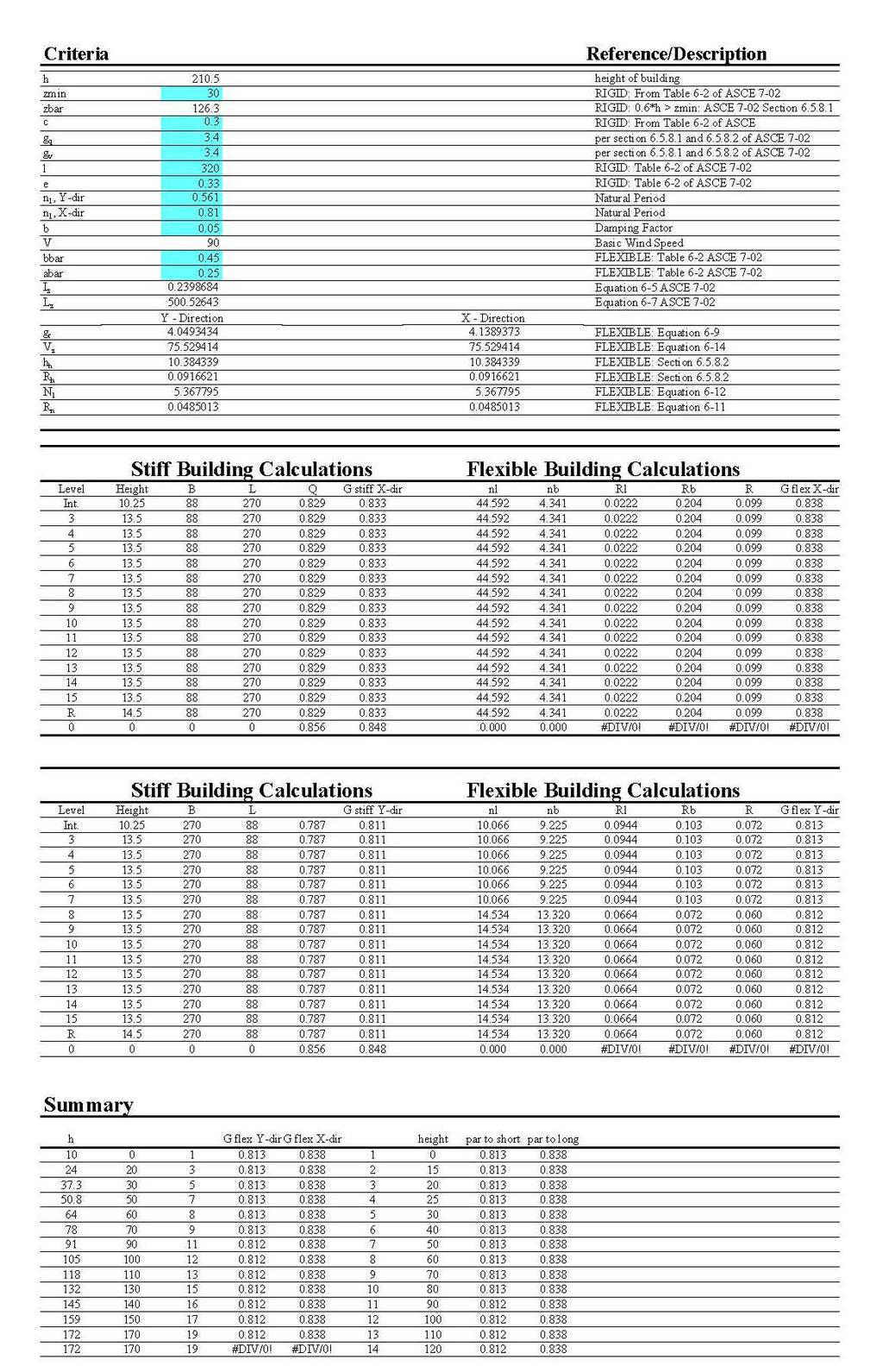
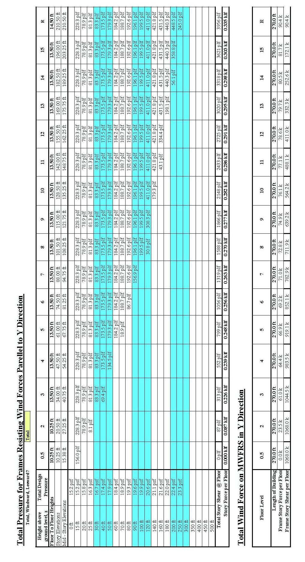
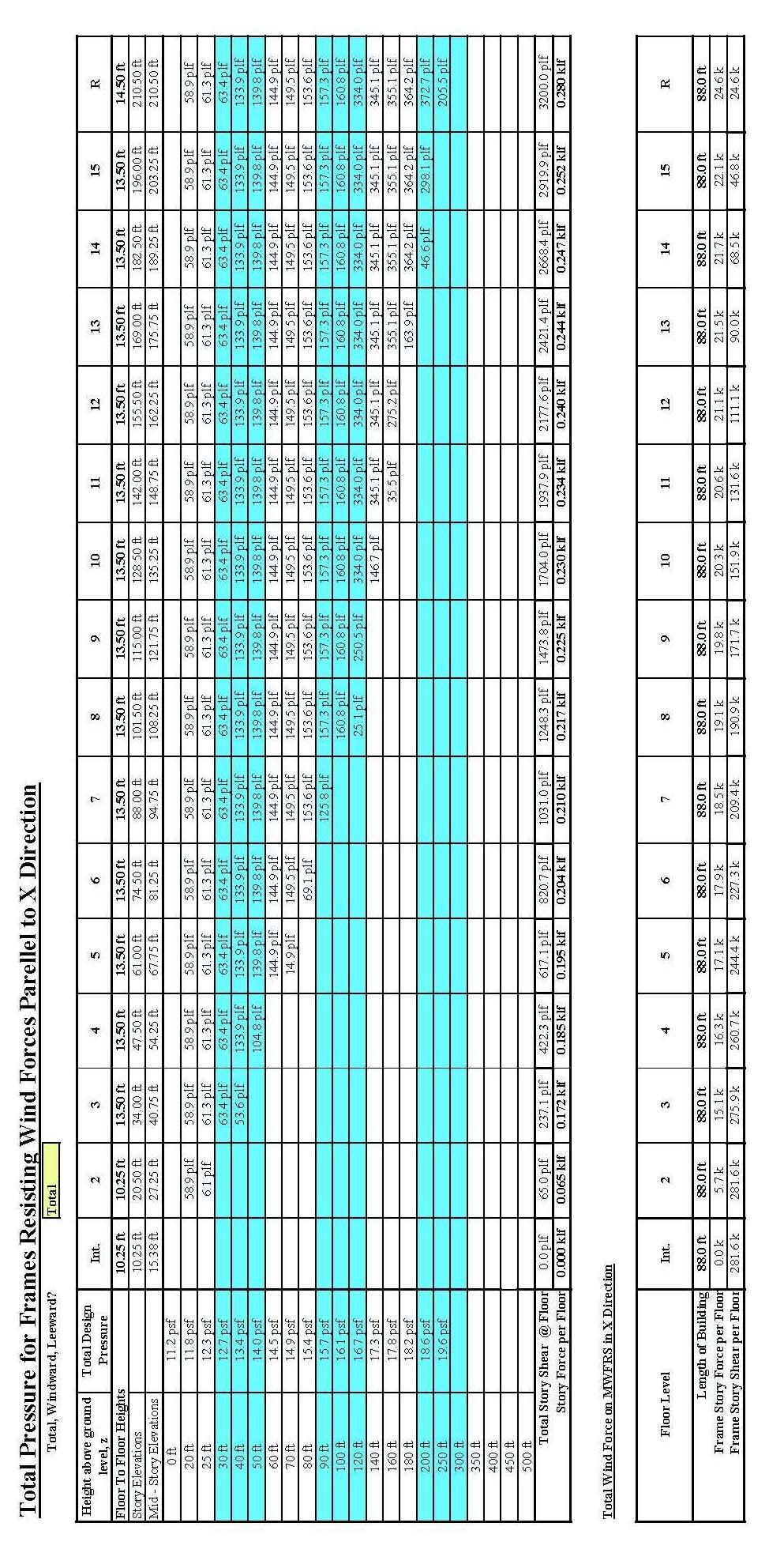
6 A.2 Lateral Loading A.2.1 Wind vi
7 vii

8 GATEWAY PLAZA viii
9 ix
10 x

11 A.2.2 Seismic xi
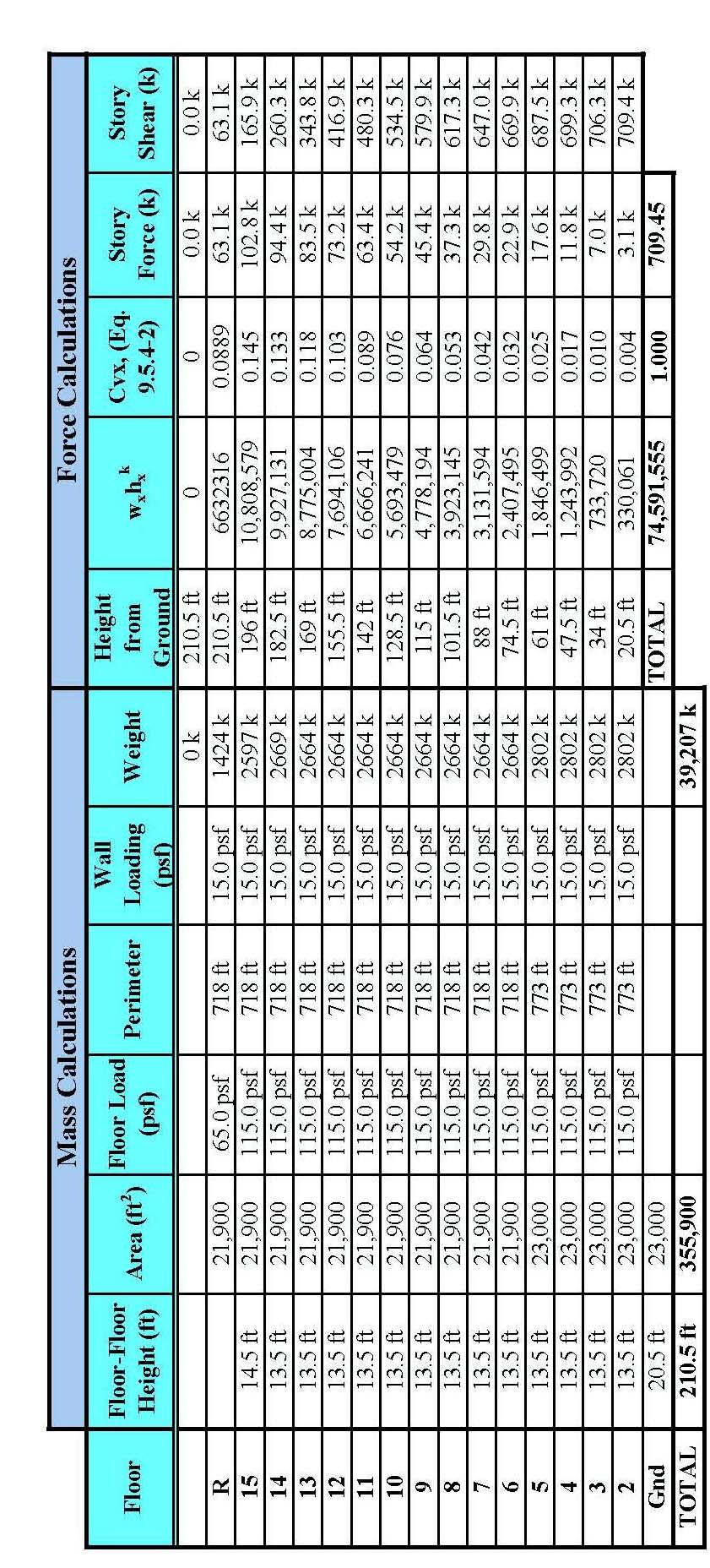
12 xii
13 APPENDIX B: PRELIMINARY MEMBER DESIGN xiii
14 B.1 Post-tensioned Slab Given: Live Load = 80 psf Dead Load = 100 psf (assuming 8 thick slab) Total Load = 180 psf Preliminary Design: Balance Load: ωn = TL ω pre Net Load: ω = 180 psf 90 psf = 90 psf n Design limits o Cover: ¾ from top and bottom o Allowable Stresses: Class U At time of jacking f ' c = 6, 000 psi Compression (18.4.2a) = 0.60 f ' c = 0.6( 6,000 psi) = 3, 600 psi Tension (18.4.2b) = 3 f ' c = psi = 232 psi At service f ' c = 6, 000 psi Compression = 0.45 f ' c = 0.45( 6,000 psi) = 2, 700 psi Tension = 6 f ' c = psi = 465psi o Average pre-compression limits = 125 psi (min) = 300 psi (max) o Target Load Balances: 60%-80% of selfweight for slabs. Use 75% ω ω Tendon profile o a = 4.0" A pre pre = 0.75slab = ( psf ) = 75 psf (4.0" + 7.0") o a B = 1.75" = 3.75" 2 Prestress Force Required to Balance 70% of selfweight xiv
15 w b = psf 52.5' = 3675plf = o ( )( ) klf Force needed in tendons to counteract the load in bay A-B. o wbl P = 8a A = 8 Check Precompression o 2 klf ( 30' ) ( 3.75"/12) ( 1323k ) = 1323k # tendons = = 49 tendons 26.6k / tendon o Actual force for banded tendons: o Actual precompression stress: 125 psi < 259 psi <300 psi o Check Interior Span Force ( )( ) 2 P actual = ( 49tendons)(26.6k) = 1303k P actual 1303k = = 259 psi 2 A 630in 8" 3.68klf 30' P = = 827k < 1303k Less force is required in the 8( 6" ) center bay. Check balance load for interior ( 1303k )( 8)( 6"/12) w b = = 5. 7klf 2 30' ( ) wb 5.7klf = = 100% w 5.25klf DL o Effective prestress force, P eff = 1303 k For further analysis, this layout was entered into RAM Concept and checked further. xv
16 B.2 Columns Typical Columns Along Column Line 1 k 2 trib. W 30' A t 790 sf f'c 6 ksi span l ab 52.5' beam 800 plf span l bc 36' w LL A t (ft 2 ) A i (ft 2 ) = A t x k Reduction = / Ai LL (k) w DL (psf) DL (k) Pu (k) w utl (psf) FEM ab R , k 'k ,580 3, k 'k ,370 4, k 'k ,160 6, k 'k ,950 7, k 'k ,740 9, k 'k ,530 11, k 'k ,320 12, k 'k ,110 14, k 'k ,900 15, k 'k ,690 17, k 'k ,480 18, k 'k ,270 20, k 'k ,060 22, k 'k ,850 23, k 'k b h γ Rn Kn ρ A s R 20 in 20 in (8) # in 26 in (14) # in 26 in (16) # in 26 in (16) # in 26 in (16) # in 26 in (16) # in 26 in (16) # in 30 in (18) # in 30 in (18) # in 30 in (18) # in 30 in (18) # in 30 in (20) # in 30 in (20) # in 30 in (20) # in 30 in (20) #14 xvi
17 Typical Columns Along Column Line 3 k 2 trib. W 30' A t 540 sf f'c 6 ksi span l ab 52.5' beam 800 plf span l bc 36' w LL A t (ft 2 ) A i (ft 2 ) = A t x k Reduction= / A i LL (k) w DL (psf) DL (k) Pu (k) w utl (psf) w udl (psf) FEM bc R , k 'k ,080 2, k 'k ,620 3, k 'k ,160 4, k 'k ,700 5, k 'k ,240 6, k 'k ,780 7, k 'k ,320 8, k 'k ,860 9, k 'k ,400 10, k 'k ,940 11, k 'k ,480 12, k 'k ,020 14, k 'k ,560 15, k 'k ,100 16, k 'k b h γ Rn Kn ρ As R 18 in 18 in (9) # in 24 in (12) # in 24 in (10) # in 24 in (10) # in 24 in (10) # in 24 in (10) # in 24 in (10) # in 24 in (16) # in 28 in (16) # in 28 in (16) # in 28 in (16) # in 28 in (16) # in 28 in (16) # in 28 in (16) # in 28 in (16) #11 xvii
18 Column Schedule C-1 C-2 C-3 C-4 C-5 C-6 C-7 C-8 22x 22 18x 18 24x 24 24x 24 22x 22 22x 26 22x 26 R (16)- #9 (18)- #4 (18)- #6 (16)- #9 (20)- #8 (16)- #8 (16)- #6 2228k 1212k 2218k 2533k 2221k 2389k 2171k 22x 26 18x 24 32x 32 22x 26 22x 26 22x 26 22x (16)- #6 (18)- #5 (18)- #7 (16)- #9 (20)- #7 (16)- #9 (16)- #6 2171k 1648k 3816k 2520k 2364k 2520k 2171k 22x 26 18x 24 32x 32 22x 26 22x 26 22x 26 22x (16)- #6 (18)- #5 (18)- #7 (16)- #6 (20)- #5 (16)- #6 (16)- #6 2171k 1648k 3816k 2171k #N/A 2171k 2171k 22x 26 18x 24 32x 32 22x 26 22x 26 22x 26 22x (16)- #6 (18)- #5 (18)- #7 (16)- #6 (20)- #5 (16)- #6 (16)- #6 2171k 1648k 3816k 2171k #N/A 2171k 2171k 22x 26 18x 24 32x 32 22x 26 22x 26 22x 26 22x (16)- #6 (18)- #5 (18)- #7 (16)- #6 (20)- #5 (16)- #6 (16)- # k k k k #N/A k k 22x 26 18x 24 32x 32 22x 26 22x 26 22x 26 22x (16)- #6 (18)- #5 (18)- #7 (16)- #6 (20)- #5 (16)- #6 (16)- #6 2171k 1648k 3816k 2171k #N/A 2171k 2171k 22x 32 18x 28 32x 32 22x 32 22x 32 22x 30 22x (16)- #6 (18)- #5 (18)- #7 (16)- #6 (20)- #6 (16)- #6 (16)- #6 2608k 1886k 3816k 2608k 2677k 2462k 2462k 22x 32 18x 28 32x 32 22x 32 22x 32 22x 30 22x 30 9 (16)- #6 (18)- #5 (18)- #7 (16)- #6 (20)- #6 (16)- #6 (16)- #6 2608k 1886k 3816k 2608k 2677k 2462k 2462k 22x 32 18x 28 32x 32 22x 32 22x 32 22x 30 22x 30 8 (16)- #6 (18)- #5 (18)- #7 (16)- #6 (20)- #6 (16)- #6 (16)- #6 2608k 1886k 3816k 2608k 2677k 2462k 2462k 22x 32 18x 28 32x 32 22x 32 22x 32 22x 30 22x 30 7 (16)- #6 (18)- #5 (18)- #7 (16)- #6 (20)- #6 (16)- #6 (16)- #6 2608k 1886k 3816k 2608k 2677k 2462k 2462k 22x 32 18x 28 32x 32 22x 32 22x 32 22x 30 22x 30 6 (16)- #6 (18)- #5 (18)- #7 (16)- #6 (20)- #6 (16)- #6 (16)- #6 2608k 1886k 3816k 2608k 2677k 2462k 2462k 22x 32 18x 28 34x 34 22x 32 22x 32 22x 30 22x 30 12x 12 5 (16)- #6 (18)- #5 (18)- #8 (16)- #6 (20)- #6 (16)- #6 (16)- #6 (8)- #4 2608k 1886k 4387k 2608k 2677k 2462k 2462k 539k 22x 32 18x 28 34x 34 22x 32 22x 32 22x 30 22x 30 12x 12 4 (16)- #6 (18)- #5 (18)- #9 (16)- #8 (20)- #8 (16)- #8 (16)- #6 (8)- #4 2608k 1886k 4534k 2827k 2950k 2681k 2462k 539k 22x 32 18x 28 34x 34 22x 32 22x 32 22x 30 22x 30 12x 12 3 (16)- #6 (18)- #5 (18)- #11 (16)- #10 (20)- #10 (16)- #10 (16)- #6 (8)- #4 2608k 1886k 4927k 3126k 3324k 2980k 2462k 539k 22x 32 18x 28 34x 34 22x 32 22x 32 22x 30 22x 30 12x 12 2 (16)- #6 (18)- #6 (18)- #14 (16)- #11 (20)- #11 (16)- #11 (16)- #6 (8)- #4 2608k 1980k 5412k 3307k 3551k 3161k 2462k 539k xviii
19 B.3 Beams Note: All beams analyzed in a similar manner to the following two procedures. Detailed Calculation of 52 Post-tensioned beams Stresses Losses Selection of Force f' c 6000 psi σ ci 3 ksi IV V f' ci 5000 psi σ cs 4 ksi F i 1078 k f pu 270 ksi σ ti 0 ksi Selection of Steel f pi 181 ksi σ ts -1 ksi 0.8fpu 216 ksi f py 243 ksi η fpu 189 ksi Input Information As 5.96 sq in L span 53' A ps 0 sq in # strands 39 dc,min 2 in h 24 in F i 1080 k Section Properties e o,u 14 in A (in 2 ) I (in 4 ) y b (in) yt (in) e o,l 14 in e o,mid 14 in z b (in) z t (in) k b (in) k t (in) e o,supp 5 in M mid-span (in-k) ω g (plf) ω LL (plf) M min M max ,400 10,825 18,041 1/Fi e o I II III IV V FEAS IBLE DOMAIN II 1/Fi eo I II III IV V 20 xix
20 Detailed Calculation of 36 Interior Post-tensioned Beam Stresses Losses Selection of Force f' c 6000 psi σ ci 3 ksi IV V f' ci 5000 psi σ cs 4 ksi F i 430 k f pu 270 ksi σ ti 0 ksi Selection of Steel f pi 181 ksi σ ts -1 ksi 0.8fpu 216 ksi f py 243 ksi η fpu 189 ksi Input Information As 2.37 sq in L span 36' A ps 0.15 sq in # strands 16 d c,min 2 in h 24 in F i 443 k Section Properties e o,u 15 in A (in 2 ) I (in 4 ) y b (in) yt (in) e o,l 15 in e o,mid 15 in z b (in) z t (in) k b (in) k t (in) e o,supp 5 in M mid-span (in-k) ω g (plf) ω LL (plf) M min M max ,400 4,807 8,200 1/Fi e o I II III IV V FEASIBLE DO MAIN II -10 1/Fi eo I II III IV V xx
21 B.4 Shearwalls The shearwalls are designed using 4000 psi concrete and use the forces for wind in the northsouth direction for the north-south walls and use the forces for seismic activity in the eastwest direction. The hand calculations below show preliminary designs and the formulas used in the following spreadsheets. V V u n φv c n = V + V s V f hd psi in c c 525 ft A f d V = v y s s o Horizontal Reinforcing = = 2 ' = ( 12" ) ' 12 = k ρ h,min A h,min = ' ( 12" )( 36' 12" ) = 175in lw = 86.4" 5 smax = min 3h = 36" = 18" 18" Try 14 : A h = in, ρ = o Vertical Reinforcing ρ = v,min 211' ρv = ' lw = 144" 3 smax = min 3h = 36" = 18" 18" Try 14 : = 183in 2, ρ = A v ( 60ksi)( ' 12" ) ( ) Av f yd 183in 2 Vs = = = 271k s 14" Vn = 525k + 271k = 796k φv = k = 597 n ( ) k 2 = xxi
22 APPENDIX C: PLANS xxii
23 C.1 Composite Steel-Foundation xxiii
24 C.2 Composite Steel-Typical Floor xxiv
25 C.3 Post-tensioned Concrete-Foundation xxv
26 C.4 Post-tensioned Concrete-Floor Framing xxvi
27 xxvii
28 C.5 Post-tensioned Concrete-Reinforcement xxviii
29 xxix
30 xxx
31 xxxi
32 APPENDIX D: BREADTH STUDIES xxxii
33 D.1 Mechanical Studies ASHRAE Standard 62-Ventilation for Indoor Air Quality Office Az (ft 2 ) Rp Pz Ra Az (ft 2 ) Vbz (cfm) Voz (cfm) Vpz (cfm) Zp (cfm) Vou (cfm) # diffusers cfm/ duct Σ xxxiii
34 D.2 Construction Studies D.2.1 Material Takeoffs Post-tensioned Concrete Beams and Slabs: Takeoffs from RAM Concept Beam Formwork Volume 687 CY Type # A Contact Area Perimeter 719' B SF 341 SFCA Floor Area SF B SF 2231 SFCA Slab thickness 8 in B SF 300 SFCA Prestressing lb B SF 672 SFCA Reinforcing tons B SF 3500 SFCA Slab Formwork sf Total 7045 SFCA Slab Edge Forms 479 SFCA Shearwalls Columns # length height Area Volume/column 2 CY 6 30' 14' 2430 SF # columns/floor ' 14' 972 SF Volume/floor 72 Total 3402 SF Composite Steel Structural Steel: Takeoffs from RAM Beam Steel 107 tons Slab Thickness 4 in # shear studs Frames 50 tons Fireproofing Beam # A Totals W24x W24x W24x Column W14x Caissons Amount Material Labor Equipment Cost A '-0" dia. x 100' 20 Ea $1,496,329 5'-0" dia. x 100' 6 Ea $918,324 6'-0" dia. x 100' 10 Ea $1,840,069 TOTAL $4,254,722 Concrete Filled, Drilled Piers A End Bearing Steel Piles Cost pile cluster $44, pile cluster $107, pile cluster $109, pile cluster $100, pile cluster $221,400 Pile caps, incl. forms and reinf $96,309 TOTAL $680,409 xxxiv
35 D.2.2 Estimates Estimate of Post-tensioned Concrete Design for One Typical Floor Slabs System Amount Material Labor Equipment Cost Beam formwork 7044 SFCA $63, slab edge forms 479 SFCA $2,432 slab formwork sf $216, Slab Reinforcing tons $72, Ungrouted Post-tensioned strand lb $58, psi Concrete 687 CY 109 $74, Placing 687 CY $11,129 Total $499,183 Columns "x24" average reinforcing 72 CY $58,392 including 4 use forms, concrete, placement, reinforcing Total $58,392 Shearwalls B " thick, plain finish, 4000 psi wall including 4 use forms, reinforcing, concrete, placement 3402 sf $97,127 Total $97,127 Total $654,702 Cost/sf $28 xxxv
36 Estimate of Composite Steel Design for One Typical Floor Slabs System Amount Material Labor Equipment Total Cost ga. 3-1/4" Metal Deck SF $60, x6 W1.4xW CSF $12, psi concrete 253 CY 81 $20, Placing concrete 253 CY $4, Curb Edging 718 LF $17,397 Total $98,171 Structural Steel Offices over 15-stories 107 TON $251, /4" dia Shear Studs $57,713 Total $309,591 Frames Columns, Beams, and Braces 50 TON $117,700 Fireproofing Decking SF $51,260 Beams SF $31,650 Columns 3506 SF $8,521 Total $91,430 TOTAL $616,892 Cost/sf $26 xxxvi

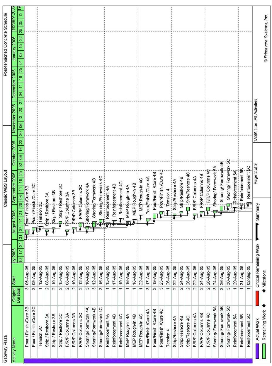
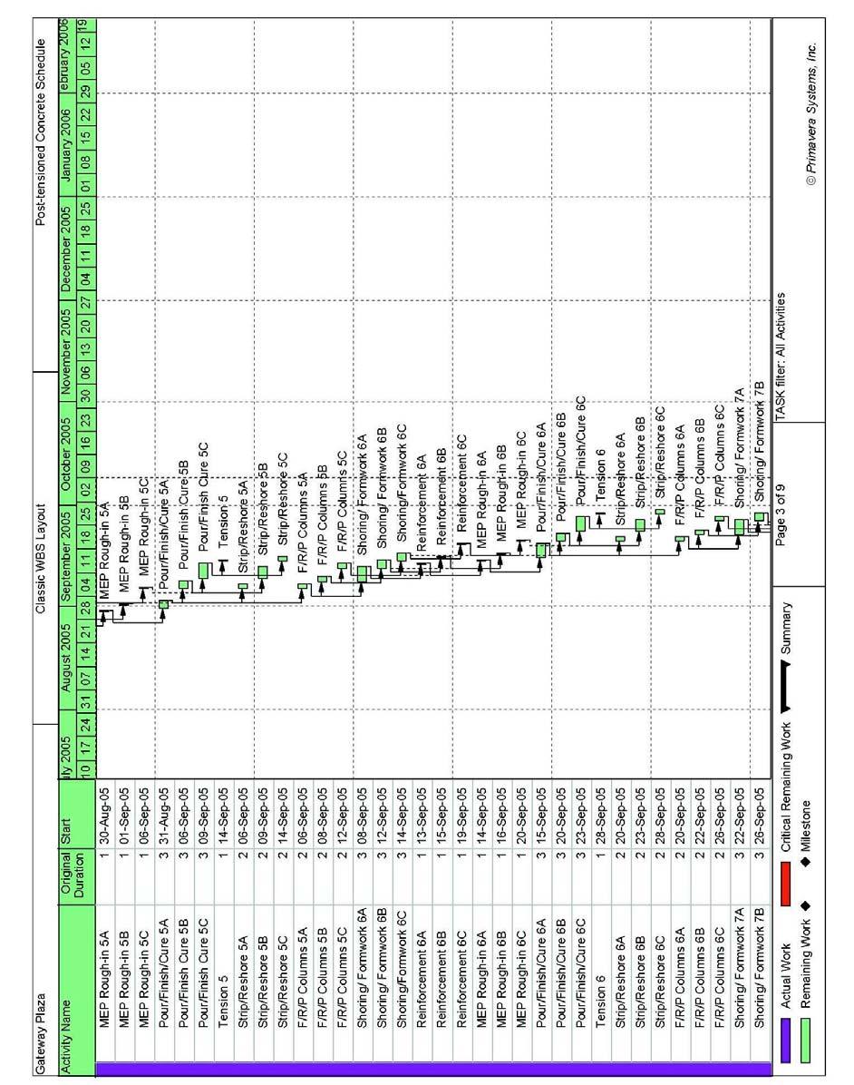
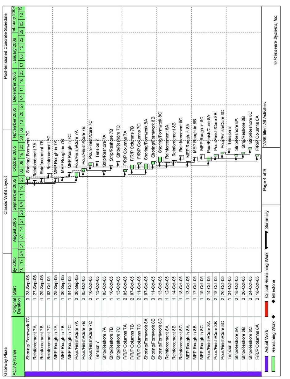
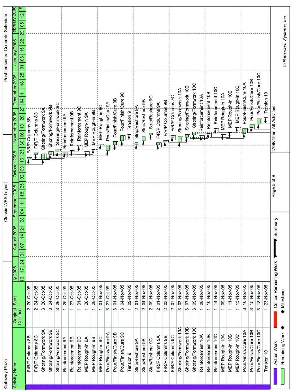
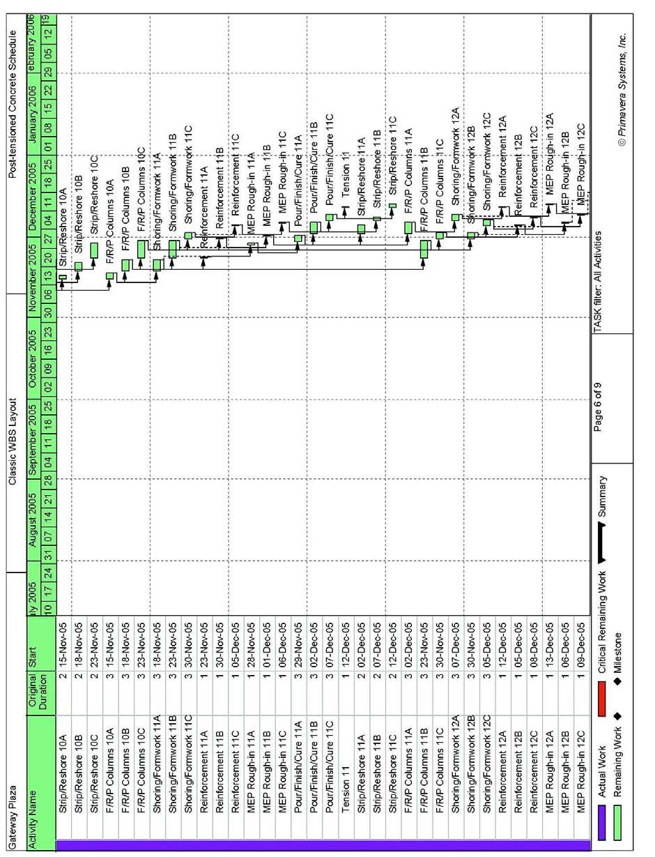
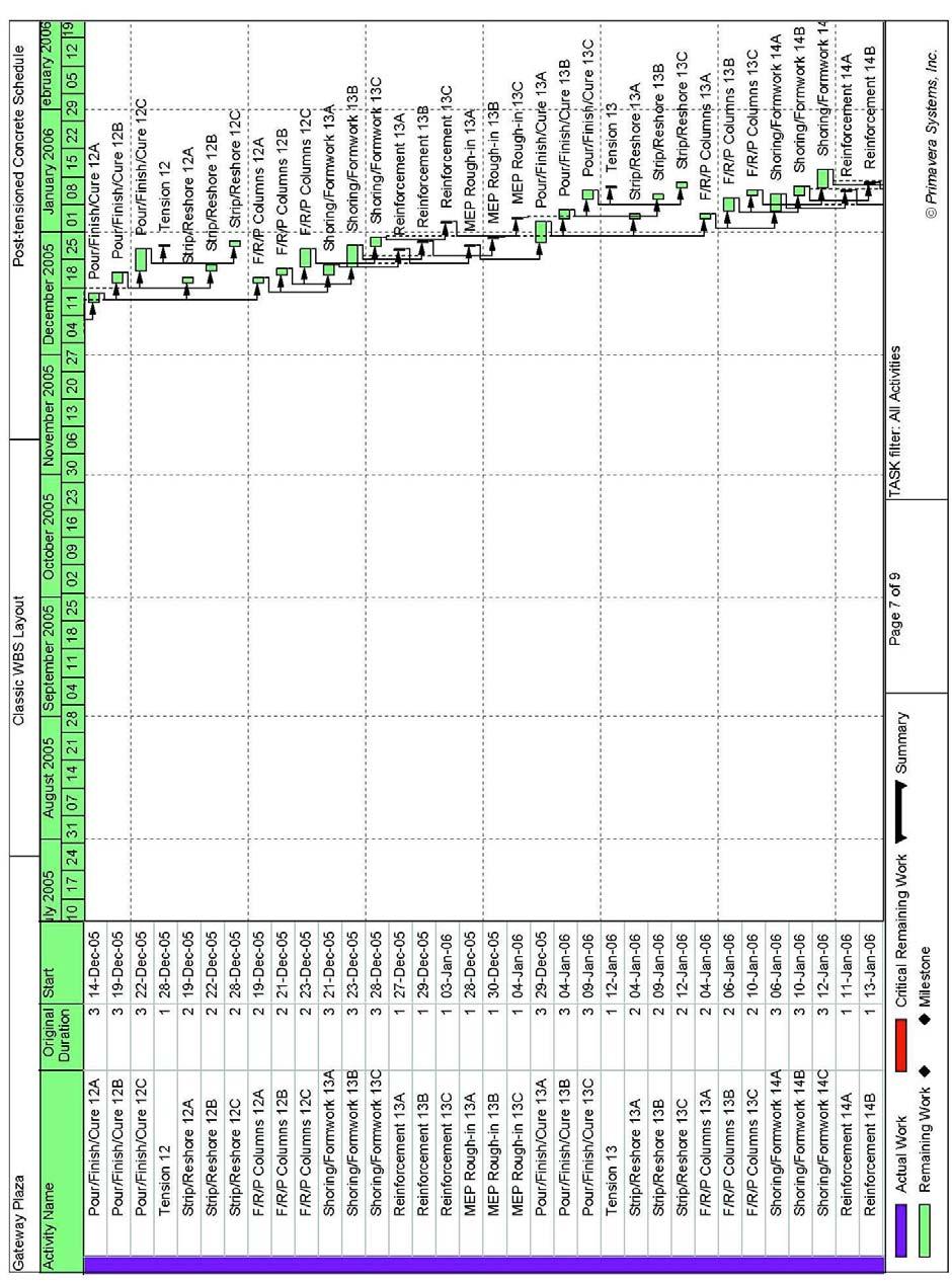
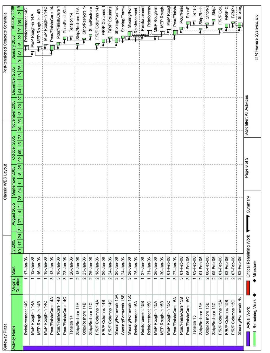
37 D.2.3 Schedule xxxvii
38 xxxviii
39 xxxix
40 xl
41 xli
42 xlii
43 xliii
44 xliv
45 xlv
46 xlvi
Chromatically Unique Bipartite Graphs With Certain 3-independent Partition Numbers III ABSTRACT
 Malaysian Chromatically Journal of Mathematical Unique Biparte Sciences Graphs with 1(1: Certain 139-16 3-Independent (007 Partition Numbers III Chromatically Unique Bipartite Graphs With Certain 3-independent
Synthesis and Characterization of New 2,3-Disubstituted Thieno[3,4-b]pyrazines: Tunable Building Blocks for Low Band Gap Conjugated Materials
![Synthesis and Characterization of New 2,3-Disubstituted Thieno[3,4-b]pyrazines: Tunable Building Blocks for Low Band Gap Conjugated Materials](/thumbs/95/123063489.jpg "Synthesis and Characterization of New 2,3-Disubstituted Thieno[3,4-b]pyrazines: Tunable Building Blocks for Low Band Gap Conjugated Materials") SUPPORTING INFORMATION Synthesis and Characterization of New 2,3-Disubstituted Thieno[3,4-b]pyrazines: Tunable Building Blocks for Low Band Gap Conjugated Materials Li Wen, Jon P. Nietfeld, Chad M. Amb,
SUPPORTING INFORMATION Synthesis and Characterization of New 2,3-Disubstituted Thieno[3,4-b]pyrazines: Tunable Building Blocks for Low Band Gap Conjugated Materials Li Wen, Jon P. Nietfeld, Chad M. Amb,
From Table 1 4. DL = [12 lb/ft 2 # in.(6 in.)] (15 ft)(10 ft) = 10,800 lb. LL = (250 lb/ft 2 )(15 ft)(10 ft) = 37,500 lb.
![From Table 1 4. DL = [12 lb/ft 2 # in.(6 in.)] (15 ft)(10 ft) = 10,800 lb. LL = (250 lb/ft 2 )(15 ft)(10 ft) = 37,500 lb.](/thumbs/86/93354768.jpg "From Table 1 4. DL = [12 lb/ft 2 # in.(6 in.)] (15 ft)(10 ft) = 10,800 lb. LL = (250 lb/ft 2 )(15 ft)(10 ft) = 37,500 lb.") 1 1. The floor of a heavy storage warehouse building is made of 6-in.-thick stone concrete. If the floor is a slab having a length of 15 ft and width of 10 ft, determine the resultant force caused by the
1 1. The floor of a heavy storage warehouse building is made of 6-in.-thick stone concrete. If the floor is a slab having a length of 15 ft and width of 10 ft, determine the resultant force caused by the
Lecture 7 Two-Way Slabs
 Lecture 7 Two-Way Slabs Two-way slabs have tension reinforcing spanning in BOTH directions, and may take the general form of one of the following: Types of Two-Way Slab Systems Lecture 7 Page 1 of 13 The
a 1 ft2 144 in 2 b 26 in.
 1 1. The floor of a heavy storage warehouse building is made of 6-in.-thick stone concrete. If the floor is a slab having a length of 15 ft and width of 10 ft, determine the resultant force caused by the
Lecture Example. Steel Deck (info from Vulcraft Steel Roof and Floor Deck Manual)
") 1 / 8 Geometry beam span L 40 ft Steel Wide Flange Beam: beam spacing s beam 10 ft F y 50 ksi construction live load LL construc 20 psf row 148 live load LL 150 psf unit weight of concrete UW conc 145
1 / 8 Geometry beam span L 40 ft Steel Wide Flange Beam: beam spacing s beam 10 ft F y 50 ksi construction live load LL construc 20 psf row 148 live load LL 150 psf unit weight of concrete UW conc 145
A.2 AASHTO Type IV, LRFD Specifications
 A.2 AASHTO Type IV, LRFD Specifications A.2.1 INTRODUCTION A.2.2 DESIGN PARAMETERS 1'-5.0" Detailed example showing sample calculations for design of typical Interior AASHTO Type IV prestressed concrete
Case Study in Reinforced Concrete adapted from Simplified Design of Concrete Structures, James Ambrose, 7 th ed.
 ARCH 631 Note Set 11 S017abn Case Study in Reinforced Concrete adapted from Simplified Design of Concrete Structures, James Ambrose, 7 th ed. Building description The building is a three-story office building
Methods for Marsh Futures Area of Interest (AOI) Elevation Zone Delineation
 Elevation Zone Delineation") PARTNERSHIP FOR THE DELAWARE ESTUARY Science Group Methods for Marsh Futures Area of Interest (AOI) Elevation Zone Delineation Date Prepared: 07/30/2015 Prepared By: Joshua Moody Suggested Citation: Moody,
PARTNERSHIP FOR THE DELAWARE ESTUARY Science Group Methods for Marsh Futures Area of Interest (AOI) Elevation Zone Delineation Date Prepared: 07/30/2015 Prepared By: Joshua Moody Suggested Citation: Moody,
A q u a b l u e a t t h e G o l d e n M i l e
 A q u a b l u e a t t h e G o l d e n M i l e H a t o R e y, P u e r t o R i c o G e n e r a l B u i l d i n g I n f o r m a t i o n Building Facts: 7-story parking structure + luxury apartments 900,000
MINISTRIES/DEPARTMENTS Internal and Extra-Budgetary Resources Total. Support Internal ECBs/ Others Total IEBR Resources Bonds Suppliers EBR
 I MINISTRY OF AGRICULTURE 2929.55 0.00 2929.55 Department of Agriculture 1950.00 0.00 1950.00 and Cooperation Department of Agricultural 629.55 0.00 629.55 Research & Education D/Animal Husbandry 300.00
Fe (III), Co (II), Ni(II), Cu(II) -3,3'-(5- -1,2,4- Co(II), Ni(II) 121
, Co (II), Ni(II), Cu(II) -3,3'-(5- -1,2,4- Co(II), Ni(II) 121") .. -1,2,4-2002 3 .,. -1,2,4- / -. :. 2002. 240.,, - -1,2,4-. (5-, - (), - -3,3-(5--1,2,4- - :, -..,, -,, -. :.. ; -. ; - - ().., 2002.,., 2002 4 3 8 10 1. -1,2,4-, 5--1()-1,2,3,4-14 1.1. -1,2,4-14 1.2.
.. -1,2,4-2002 3 .,. -1,2,4- / -. :. 2002. 240.,, - -1,2,4-. (5-, - (), - -3,3-(5--1,2,4- - :, -..,, -,, -. :.. ; -. ; - - ().., 2002.,., 2002 4 3 8 10 1. -1,2,4-, 5--1()-1,2,3,4-14 1.1. -1,2,4-14 1.2.
TABLE OF CONTANINET 1. Design criteria. 2. Lateral loads. 3. 3D finite element model (SAP2000, Ver.16). 4. Design of vertical elements (CSI, Ver.9).
. 4. Design of vertical elements (CSI, Ver.9).") TABLE OF CONTANINET 1. Design criteria. 2. Lateral loads. 2-1. Wind loads calculation 2-2. Seismic loads 3. 3D finite element model (SAP2000, Ver.16). 4. Design of vertical elements (CSI, Ver.9). 4-1.
TABLE OF CONTANINET 1. Design criteria. 2. Lateral loads. 2-1. Wind loads calculation 2-2. Seismic loads 3. 3D finite element model (SAP2000, Ver.16). 4. Design of vertical elements (CSI, Ver.9). 4-1.
Structural Specialization
 Structural Specialization Project: Size beams for the given structural layout using loading conditions specified in the International Building Code. Contents Typical Floor Beam Layout... 2 Building Sections...
Pre-stressed concrete = Pre-compression concrete Pre-compression stresses is applied at the place when tensile stress occur Concrete weak in tension
 Pre-stressed concrete = Pre-compression concrete Pre-compression stresses is applied at the place when tensile stress occur Concrete weak in tension but strong in compression Steel tendon is first stressed
Chapter 4 Seismic Design Requirements for Building Structures
 Chapter 4 Seismic Design Requirements for Building Structures where: F a = 1.0 for rock sites which may be assumed if there is 10 feet of soil between the rock surface and the bottom of spread footings
Suspended high-rise. Suspended high-rise Copyright G G Schierle, press Esc to end, for next, for previous slide 1
 Suspended high-rise Suspended high-rise Copyright G G Schierle, 2001-06 press Esc to end, for next, for previous slide 1 Suspended high-rise 1 Gravity load path 2 Differential deflection 3 Prestress to
Appendix J. Example of Proposed Changes
 Appendix J Example of Proposed Changes J.1 Introduction The proposed changes are illustrated with reference to a 200-ft, single span, Washington DOT WF bridge girder with debonded strands and no skew.
Annex - R C Design Formulae and Data
 The design formulae and data provided in this Annex are for education, training and assessment purposes only. They are based on the Hong Kong Code of Practice for Structural Use of Concrete 2013 (HKCP-2013).
PUNCHING SHEAR CALCULATIONS 1 ACI 318; ADAPT-PT
 Structural Concrete Software System TN191_PT7_punching_shear_aci_4 011505 PUNCHING SHEAR CALCULATIONS 1 ACI 318; ADAPT-PT 1. OVERVIEW Punching shear calculation applies to column-supported slabs, classified
Factorizations of b n ±1, Up to High Powers. Third Edition. John Brillhart, D. H. Lehmer J. L. Selfridge, Bryant Tuckerman, and S. S. Wagstaff, Jr.
 CONTEMPORARY MATHEMATICS 22 Factorizations of b n ±1, b = 2, 3, 5, 6, 7,10, 11, 12 Up to High Powers Third Edition John Brillhart, D. H. Lehmer J. L. Selfridge, Bryant Tuckerman, and S. S. Wagstaff, Jr.
Serviceability Deflection calculation
 Chp-6:Lecture Goals Serviceability Deflection calculation Deflection example Structural Design Profession is concerned with: Limit States Philosophy: Strength Limit State (safety-fracture, fatigue, overturning
Appendix K Design Examples
 Appendix K Design Examples Example 1 * Two-Span I-Girder Bridge Continuous for Live Loads AASHTO Type IV I girder Zero Skew (a) Bridge Deck The bridge deck reinforcement using A615 rebars is shown below.
Beam Design - Shed Roof Back Wall Beam-S
 Beam Design - Shed Roof Back Wall Beam-S 1. Beam Data Load Type: Uniform Dist. Load Support: Simple Beam Beam Type: Glulam Species: Western Species Grade: 24F-V4 1.8E DF/DF Size: 2.5 x 6 Design Span (L):
Design of Reinforced Concrete Structures (II)
") Design of Reinforced Concrete Structures (II) Discussion Eng. Mohammed R. Kuheil Review The thickness of one-way ribbed slabs After finding the value of total load (Dead and live loads), the elements are
Design of Reinforced Concrete Structures (II) Discussion Eng. Mohammed R. Kuheil Review The thickness of one-way ribbed slabs After finding the value of total load (Dead and live loads), the elements are
Example Stayed beam with two pylons
 Example Stayed beam with two pylons A roof structure is a stayed beam. The roof span is 300 ft. Stay vertical run is 20 ft. The deck is weighs 12 PSF. Beams have a transverse spacing equal to 40 feet.
Beam Design - Pine Tree
 - Pine Tree 1. Beam Data Load Type: Uniform Dist. Load Support: Simple Beam Beam Type: Sawn Lumber Species: Southern Pine Grade: SP DSS Size: 2 x 8 Design Span (L): 11.83 ft. Clear Span: 11.67 ft. Total
Beam Design - FLOOR JOIST
 Beam Design - FLOOR JOIST 1. Beam Data Load Type: Uniform Dist. Load Support: Simple Beam Beam Type: Sawn Lumber Species: Douglas Fir-Larch Grade: DF No.2 Size: 2 x 10 Design Span (L): 11.83 ft. Clear
Final Analysis Report MIE 313 Design of Mechanical Components
 Final Analysis Report MIE 313 Design of Mechanical Components Juliana Amado Charlene Nestor Peter Walsh Table of Contents Abstract:...iii Introduction:... 4 Procedure:... 5 Results:... 6 Reliability:...
Sway Column Example. PCA Notes on ACI 318
 Sway Column Example PCA Notes on ACI 318 ASDIP Concrete is available for purchase online at www.asdipsoft.com Example 11.2 Slenderness Effects for Columns in a Sway Frame Design columns C1 and C2 in the
 1/29/2010 Page 2 of 65 1/29/2010 Page 3 of 65 1/29/2010 Page 4 of 65 Project Information 1/29/2010 Page 5 of 65 Muckleshoot Indian Tribe Project Number 09-118 West Detention Vault West Vault City of Auburn
INVESTIGATION INTO THE EFFECTS OF VARIABLE ROW SPACING IN BOLTED TIMBER CONNECTIONS SUBJECTED TO REVERSE CYCLIC LOADING CALEB JESSE KNUDSON
 INVESTIGATION INTO THE EFFECTS OF VARIABLE ROW SPACING IN BOLTED TIMBER CONNECTIONS SUBJECTED TO REVERSE CYCLIC LOADING By CALEB JESSE KNUDSON A thesis submitted in partial fulfillment of the requirements
AISC LRFD Beam Design in the RAM Structural System
 Model: Verification11_3 Typical Floor Beam #10 W21x44 (10,3,10) AISC 360-05 LRFD Beam Design in the RAM Structural System Floor Loads: Slab Self-weight: Concrete above flute + concrete in flute + metal
Summer Review Packet AP Calculus
 Summer Review Packet AP Calculus ************************************************************************ Directions for this packet: On a separate sheet of paper, show your work for each problem in this
SPECIFIC VERIFICATION Chapter 5
 As = 736624/(0.5*413.69) = 3562 mm 2 (ADAPT 3569 mm 2, B29, C6) Data Block 27 - Compressive Stresses The initial compressive strength, f ci, is the strength entered in the Material/Concrete input screen.
Two Way Beam Supported Slab
 Two Way Beam Supported Slab Part 2 The following example was done by Mr. Naim Hassan, 3 rd Year 2 nd Semester Student of CE Dept., AUST 16 The following Example was done by Md. Mahmudun Nobe, ID -.01.03.078,
CHAPTER 5. T a = 0.03 (180) 0.75 = 1.47 sec 5.12 Steel moment frame. h n = = 260 ft. T a = (260) 0.80 = 2.39 sec. Question No.
 0.75 = 1.47 sec 5.12 Steel moment frame. h n = = 260 ft. T a = (260) 0.80 = 2.39 sec. Question No.") CHAPTER 5 Question Brief Explanation No. 5.1 From Fig. IBC 1613.5(3) and (4) enlarged region 1 (ASCE 7 Fig. -3 and -4) S S = 1.5g, and S 1 = 0.6g. The g term is already factored in the equations, thus
CHAPTER 5 Question Brief Explanation No. 5.1 From Fig. IBC 1613.5(3) and (4) enlarged region 1 (ASCE 7 Fig. -3 and -4) S S = 1.5g, and S 1 = 0.6g. The g term is already factored in the equations, thus
*Refer to IBC Section , applicable when fall protection is required. Glass stresses are designed for a safety factor of of 4.0 (IBC ).
.") Architectural Railing Division C.R.Laurence Co., Inc. 2503 E Vernon Ave. Los Angeles, CA 90058 (T) 800.421.6144 (F) 800.587.7501 www.crlaurence.com 12 JAN 2011 SUBJ: TAPER-LOC SYSTEM DRY-GLAZE LAMINATED
Architectural Railing Division C.R.Laurence Co., Inc. 2503 E Vernon Ave. Los Angeles, CA 90058 (T) 800.421.6144 (F) 800.587.7501 www.crlaurence.com 12 JAN 2011 SUBJ: TAPER-LOC SYSTEM DRY-GLAZE LAMINATED
Model for Dredging a Horizontal Trapezoidal Open Channel with Hydraulic Jump
 Journal of Mathematics Research; Vol. 4, No. 3; 2012 ISSN 1916-9795 E-ISSN 1916-9809 Published by Canadian Center of Science and Education Model for Dredging a Horizontal Trapezoidal Open Channel with
A Revised Denotational Semantics for the Dataflow Algebra. A. J. Cowling
 Verification and Testing Research Group, Department of Computer Science, University of Sheffield, Regent Court, 211, Portobello Street, Sheffield, S1 4DP, United Kingdom Email: A.Cowling @ dcs.shef.ac.uk
Lecture-04 Design of RC Members for Shear and Torsion
 Lecture-04 Design of RC Members for Shear and Torsion By: Prof. Dr. Qaisar Ali Civil Engineering Department UET Peshawar drqaisarali@uetpeshawar.edu.pk www.drqaisarali.com 1 Topics Addressed Design of
Chapter 2. Design for Shear. 2.1 Introduction. Neutral axis. Neutral axis. Fig. 4.1 Reinforced concrete beam in bending. By Richard W.
 Chapter 2 Design for Shear By Richard W. Furlong 2.1 Introduction Shear is the term assigned to forces that act perpendicular to the longitudinal axis of structural elements. Shear forces on beams are
Suspended Beam Roof with Pylons
 Cable Supported Structures George.Hearn@colorado.edu 25 Suspended Beam Roof with Pylons A roof structure is a suspended beam. The roof span is 200 ft. Main cable sag is 20 ft. Suspender length varies.
Stability design for frame type structures
 Stability design for frame type structures Delft University of Technology Faculty of Civil Engineering and Geoscience Section of Structural echanics aster thesis report Appendices Ing. R. P. Veerman I
3.4 Reinforced Concrete Beams - Size Selection
 CHAPER 3: Reinforced Concrete Slabs and Beams 3.4 Reinforced Concrete Beams - Size Selection Description his application calculates the spacing for shear reinforcement of a concrete beam supporting a uniformly
Dorling fbetw.tex V1-04/12/2012 6:10 P.M. Page xi
 Dorling fbetw.tex V1-04/12/2012 6:10 P.M. Page xi List of figures P.1 Born in England, Scotland or Wales Britain 1981 (four levels each), ward map (wards are used to define most other administrative areas
Structural Calculations For:
 Structural Calculations For: Project: Address: Job No. Revision: Date: 1400 N. Vasco Rd. Livermore, CA 94551 D031014 Delta 1 - Plan Check May 8, 2015 Client: Ferreri & Blau MEMBER REPORT Roof, Typical
RETAINING WALL LOADS: Horizontal Equivalent Fluid Pressure = pcf. (Load Case = Soil)
") QuickWall 8.0 - RETAINING WALL ANALYSIS AND DESIGN ================================================================================ Job ID : Job Description : Designed By : ================================================================================
QuickWall 8.0 - RETAINING WALL ANALYSIS AND DESIGN ================================================================================ Job ID : Job Description : Designed By : ================================================================================
Beam Design - Awning
 Beam Design - Awning 1. Beam Data Load Type: Uniform Dist. Load Support: Simple Beam Beam Type: Sawn Lumber Species: Douglas Fir-Larch Grade: DF No.2 Size: 4 x 12 Design Span (L): 21.50 ft. Clear Span:
Preferred practice on semi-integral abutment layout falls in the following order:
 GENERAL INFORMATION: This section of the chapter establishes the practices and requirements necessary for the design and detailing of semi-integral abutments. For general requirements and guidelines on
DL CMU wall = 51.0 (lb/ft 2 ) 0.7 (ft) DL beam = 2.5 (lb/ft 2 ) 18.0 (ft) 5
 0.7 (ft) DL beam = 2.5 (lb/ft 2 ) 18.0 (ft) 5") SUJECT: HEADER EAM SELECTION SHEET 108 of 131 INTERIOR HEADER EAM SELECTION - ay length = 36 ft. (stairwell) INTERIOR HEADER EAM Header eam 1 2 Total ay Length = 36 (ft) Total ay Width = 10 (ft) 20.5 Fill
SUJECT: HEADER EAM SELECTION SHEET 108 of 131 INTERIOR HEADER EAM SELECTION - ay length = 36 ft. (stairwell) INTERIOR HEADER EAM Header eam 1 2 Total ay Length = 36 (ft) Total ay Width = 10 (ft) 20.5 Fill
EP elements in rings
 EP elements in rings Dijana Mosić, Dragan S. Djordjević, J. J. Koliha Abstract In this paper we present a number of new characterizations of EP elements in rings with involution in purely algebraic terms,
c 2011 JOSHUA DAVID JOHNSTON ALL RIGHTS RESERVED
 c 211 JOSHUA DAVID JOHNSTON ALL RIGHTS RESERVED ANALYTICALLY AND NUMERICALLY MODELING RESERVOIR-EXTENDED POROUS SLIDER AND JOURNAL BEARINGS INCORPORATING CAVITATION EFFECTS A Dissertation Presented to
DIELECTRIC PROPERTIES OF MIXTURES OF CLAY-WATER-ORGANIC COMPOUNDS
 DIELECTRIC PROPERTIES OF MIXTURES OF CLAY-WATER-ORGANIC COMPOUNDS By Birsen Canan ABSTRACT The propagation of an electromagnetic wave through a material is dependent on the electrical and magnetic properties
Survey of Geometry. Supplementary Notes on Elementary Geometry. Paul Yiu. Department of Mathematics Florida Atlantic University.
 Survey of Geometry Supplementary Notes on Elementary Geometry Paul Yiu Department of Mathematics Florida tlantic University Summer 2007 ontents 1 The Pythagorean theorem i 1.1 The hypotenuse of a right
B U I L D I N G D E S I G N
 B U I L D I N G D E S I G N 10.1 DESIGN OF SLAB P R I O D E E P C H O W D H U R Y C E @ K 8. 0 1 7 6 9 4 4 1 8 3 DESIGN BY COEFFICIENT METHOD Loads: DL = 150 pc LL = 85 pc Material Properties: c = 3000
Beam Design - Trotin Project
 Beam Design - Trotin Project 1. Beam Data Load Type: Uniform Dist. Load Support: Simple Beam Beam Type: Glulam Species: Western Species Grade: 24F-V4 1.8E DF/DF Size: 3.125 x 13.5 Design Span (L): 14.98
DIVISION: METALS SECTION: METAL FASTENINGS SECTION: STEEL DECKING REPORT HOLDER: PNEUTEK, INC.
 ICC ES Report ICC ES () 7 () www.icc es.org Most Widely Accepted and Trusted ESR 1 Reissued /1 This report is subject to renewal /. DIVISION: METALS SECTION: METAL FASTENINGS SECTION: 1 STEEL ING REPORT
DESIGN EXAMPLES APPENDIX A
 APPENDIX A DESIGN EXAMPLES Comparative Shrinkage of Sawn Timber and Glulam Beams / 499 Simple Beam Design / 500 Upside-Down Beam Analysis / 50 Tension-face Notch / 504 Compression-face Notch / 505 Sloped
NICE-PACK ALCOHOL PREP ROOM PLATFORM CALCULATIONS
 DESIGN STATEMENT THIS GALVANISED STEEL PLATFORM IS ANALYSED USING THE ALLOWABLE STRESS DESIGN METHOD TO DETERMINE MATERIAL STRENGTH. MEMBER SIZES AND FASTENERS ARE CHOSEN NOT SO MUCH FOR THEIR STRENGTH
NEW METHODS OF SPECIFIC FLUORINATION
 NEW METHODS O SPECIIC LUORINATION D. H. R. BARTON Department of Chemistry, Imperial College, London, S. W.7., U.K. and Research Institute for Medicine and Chemistry, 49 Amherst Street, Cambridge, Mass.,
Design of a Balanced-Cantilever Bridge
 Design of a Balanced-Cantilever Bridge CL (Bridge is symmetric about CL) 0.8 L 0.2 L 0.6 L 0.2 L 0.8 L L = 80 ft Bridge Span = 2.6 L = 2.6 80 = 208 Bridge Width = 30 No. of girders = 6, Width of each girder
Case Study in Reinforced Concrete adapted from Simplified Design of Concrete Structures, James Ambrose, 7 th ed.
 ARCH 631 Note Set 11 F015abn Case Study in Reinfored Conrete adapted from Simplified Design of Conrete Strutures, James Ambrose, 7 th ed. Building desription The building is a three-story offie building
Characteristics of a Force Loads on Structures. Dead Load. Load Types Dead Live Wind Snow Earthquake. Load Combinations ASD LRFD
 Architecture 314 Structures I Characteristics of a Force Loads on Structures Load Types Dead Live Wind Snow Earthquake Load Combinations ASD LRFD University of Michigan, TCAUP Structures I Slide 1 of 27
3.5 Reinforced Concrete Section Properties
 CHAPER 3: Reinforced Concrete Slabs and Beams 3.5 Reinforced Concrete Section Properties Description his application calculates gross section moment of inertia neglecting reinforcement, moment of inertia
PROPOSED SATSANG HALL TECHNICAL REPORT
 PROPOSED SATSANG HALL - VERTICAL STRIP V1 1 ------------------------------------------------------------------------------ ADAPT CORPORATION STRUCTURAL CONCRETE SOFTWARE SYSTEM 1733 Woodside Road, Suite
Attachment K. Supplemental Shear Test Information
 Attachment K. Supplemental Shear Test Information Computer Program Due to the iterative nature of shear design following the General Procedure in Article 5.8.3.4.2 of the AASHTO LRFD Bridge Specifications
MAXIMUM SUPERIMPOSED UNIFORM ASD LOADS, psf SINGLE SPAN DOUBLE SPAN TRIPLE SPAN GAGE
 F-DEK ROOF (ASD) 1-1/2" high x 6" pitch x 36" wide SECTION PROPERTIES GAGE Wd 22 1.63 20 1.98 18 2.62 16 3.30 I D (DEFLECTION) 0.142 0.173 0.228 fy = 40 ksi Sp Sn 0.122 0.135 708 815 905 1211 1329 2365
Earthquake Loads According to IBC IBC Safety Concept
 Earthquake Loads According to IBC 2003 The process of determining earthquake loads according to IBC 2003 Spectral Design Method can be broken down into the following basic steps: Determination of the maimum
Chapter 9: Column Analysis and Design
 Chapter 9: Column Analysis and Design Introduction Columns are usually considered as vertical structural elements, but they can be positioned in any orientation (e.g. diagonal and horizontal compression
Biology IA & IB Syllabus Mr. Johns/Room 2012/August,
 Biology IA & IB Syllabus Mr. Johns/Room 2012/August, 2017-2018 Description of Course: A study of the natural world centers on cellular structure and the processes of life. First semester topics include:
Design of a Multi-Storied RC Building
 Design of a Multi-Storied RC Building 16 14 14 3 C 1 B 1 C 2 B 2 C 3 B 3 C 4 13 B 15 (S 1 ) B 16 (S 2 ) B 17 (S 3 ) B 18 7 B 4 B 5 B 6 B 7 C 5 C 6 C 7 C 8 C 9 7 B 20 B 22 14 B 19 (S 4 ) C 10 C 11 B 23
Chapter (6) Geometric Design of Shallow Foundations
 Geometric Design of Shallow Foundations") Chapter (6) Geometric Design of Shallow Foundations Introduction As we stated in Chapter 3, foundations are considered to be shallow if if [D (3 4)B]. Shallow foundations have several advantages: minimum
Chapter (6) Geometric Design of Shallow Foundations Introduction As we stated in Chapter 3, foundations are considered to be shallow if if [D (3 4)B]. Shallow foundations have several advantages: minimum
URL: Publisher: Elsevier. This document has been downloaded from MUEP (
 This is an author produced version of a paper published in Atomic Data and Nuclear Data Tables. This paper has been peer-reviewed but does not include the final publisher proof-corrections or journal pagination.
PEER/SSC Tall Building Design. Case study #2
 PEER/SSC Tall Building Design Case study #2 Typical Plan View at Ground Floor and Below Typical Plan View at 2 nd Floor and Above Code Design Code Design Shear Wall properties Shear wall thickness and
VISUALIZATION IN SCIENCE EDUCATION
 VISUALIZATION IN SCIENCE EDUCATION Models and Modeling in Science Education VOLUME 1 Series Editor: Professor J. K. Gilbert Institute of Education The University of Reading UK Editorial Board: Professor
Job No. Sheet No. Rev. CONSULTING Engineering Calculation Sheet. Member Design - Steel Composite Beam XX 22/09/2016
 CONSULTING Engineering Calculation Sheet jxxx 1 Member Design - Steel Composite Beam XX Introduction Chd. 1 Grade 50 more common than Grade 43 because composite beam stiffness often 3 to 4 times non composite
GENERAL INFORMATION FOR COLUMN BASE REACTIONS
 U09Y0061A - GaragePlus - RV Storage R1 of 12 1050 North Watery Lane Ph: (435) 919-3100 Brigham City, UT 84302Fax: (435) 919-3101 Page R1 of Date: 3/24/09 GENERAL INFORMATION FOR COLUMN BASE REACTIONS FOR
Sabah Shawkat Cabinet of Structural Engineering Walls carrying vertical loads should be designed as columns. Basically walls are designed in
 Sabah Shawkat Cabinet of Structural Engineering 17 3.6 Shear walls Walls carrying vertical loads should be designed as columns. Basically walls are designed in the same manner as columns, but there are
Transient Analysis of Single Phase Transformer Using State Model
 Transient Analysis of Single Phase Transformer Using State Model Rikta Majumder 1, Suman Ghosh 2, Rituparna Mukherjee 3 Assistant Professor, Department of Electrical Engineering, GNIT, Kolkata, West Bengal,
Civil & Structural Engineering Design Services Pty. Ltd.
 Client: EXTREME MARQUEES PTY. LTD. Project: Design check 24.4m x 12.2m x 6.4m The Platoon Tent Structure (3m Bay) for 80km/hr Wind Speed. Reference: Extreme Marquees Pty Ltd Technical Data Report by: KZ
DESIGN AND DETAILING OF COUNTERFORT RETAINING WALL
 DESIGN AND DETAILING OF COUNTERFORT RETAINING WALL When the height of the retaining wall exceeds about 6 m, the thickness of the stem and heel slab works out to be sufficiently large and the design becomes
TABLE OF CONTENTS SECTION TITLE PAGE 2 PRINCIPLES OF SEISMIC ISOLATION OF BRIDGES 3
 TABLE OF CONTENTS SECTION TITLE PAGE 1 INTRODUCTION 1 2 PRINCIPLES OF SEISMIC ISOLATION OF BRIDGES 3 3 ANALYSIS METHODS OF SEISMICALLY ISOLATED BRIDGES 5 3.1 Introduction 5 3.2 Loadings for the Analysis
THE EFFECTS OF LONG-DURATION EARTHQUAKES ON CONCRETE BRIDGES WITH POORLY CONFINED COLUMNS THERON JAMES THOMPSON
 THE EFFECTS OF LONG-DURATION EARTHQUAKES ON CONCRETE BRIDGES WITH POORLY CONFINED COLUMNS By THERON JAMES THOMPSON A thesis submitted in partial fulfillment of the requirement for the degree of MASTERS
Static & Dynamic. Analysis of Structures. Edward L.Wilson. University of California, Berkeley. Fourth Edition. Professor Emeritus of Civil Engineering
 Static & Dynamic Analysis of Structures A Physical Approach With Emphasis on Earthquake Engineering Edward LWilson Professor Emeritus of Civil Engineering University of California, Berkeley Fourth Edition
FLEXURAL RESISTANCE OF LONGITUDINALLY STIFFENED PLATE GIRDERS
 FLEXURAL RESISTANCE OF LONGITUDINALLY STIFFENED PLATE GIRDERS A Dissertation Presented to The Academic Faculty By Lakshmi Priya Palamadai Subramanian In Partial Fulfillment of the Requirements for the
Concrete and Masonry Structures 1 Office hours
 Concrete and Masonry Structures 1 Petr Bílý, office B731 http://people.fsv.cvut.cz/www/bilypet1 Courses in English Concrete and Masonry Structures 1 Office hours Credit receiving requirements General knowledge
CHAPTER 4. Design of R C Beams
 CHAPTER 4 Design of R C Beams Learning Objectives Identify the data, formulae and procedures for design of R C beams Design simply-supported and continuous R C beams by integrating the following processes
FRAME ANALYSIS. Dr. Izni Syahrizal bin Ibrahim. Faculty of Civil Engineering Universiti Teknologi Malaysia
 FRAME ANALYSIS Dr. Izni Syahrizal bin Ibrahim Faculty of Civil Engineering Universiti Teknologi Malaysia Email: iznisyahrizal@utm.my Introduction 3D Frame: Beam, Column & Slab 2D Frame Analysis Building
Job No. Sheet No. Rev. CONSULTING Engineering Calculation Sheet
 CONSULTING Engineering Calculation Sheet E N G I N E E R S Consulting Engineers jxxx 1 Structural Description The two pinned (at the bases) portal frame is stable in its plane due to the moment connection
Support Reactions: a + M C = 0; 800(10) F DE(4) F DE(2) = 0. F DE = 2000 lb. + c F y = 0; (2000) - C y = 0 C y = 400 lb
 F DE(4) F DE(2) = 0. F DE = 2000 lb. + c F y = 0; (2000) - C y = 0 C y = 400 lb") 06 Solutions 46060_Part1 5/27/10 3:51 P Page 334 6 11. The overhanging beam has been fabricated with a projected arm D on it. Draw the shear and moment diagrams for the beam C if it supports a load of
06 Solutions 46060_Part1 5/27/10 3:51 P Page 334 6 11. The overhanging beam has been fabricated with a projected arm D on it. Draw the shear and moment diagrams for the beam C if it supports a load of
1. ARRANGEMENT. a. Frame A1-P3. L 1 = 20 m H = 5.23 m L 2 = 20 m H 1 = 8.29 m L 3 = 20 m H 2 = 8.29 m H 3 = 8.39 m. b. Frame P3-P6
 Page 3 Page 4 Substructure Design. ARRANGEMENT a. Frame A-P3 L = 20 m H = 5.23 m L 2 = 20 m H = 8.29 m L 3 = 20 m H 2 = 8.29 m H 3 = 8.39 m b. Frame P3-P6 L = 25 m H 3 = 8.39 m L 2 = 3 m H 4 = 8.5 m L
4.3 Moment Magnification
 CHAPTER 4: Reinforced Concrete Columns 4.3 Moment Magnification Description An ordinary or first order frame analysis does not include either the effects of the lateral sidesway deflections of the column
Topic 2060 Gibbs Energies; Salt Solutions; Aqueous Mixtures The solubilities of chemical substance j in two liquids l
 Topic 6 Gibbs Energies; Salt Solutions; Aqueous Mixtures The solubilities of chemical substance in two liquids l and l (at the same T and p) offers a method for comparing the reference chemical potentials,
Assignment 1 - actions
 Assignment 1 - actions b = 1,5 m a = 1 q kn/m 2 Determine action on the beam for verification of the ultimate limit state. Axial distance of the beams is 1 to 2 m, cross section dimensions 0,45 0,20 m
Dating Approximation and Analysis of Select Mars Surface Features
 Dating Approximation and Analysis of Select Mars Surface Features ASTR498 Fall 2006 Dr. Hayes-Gehrke Ryan Ashford Jon Croco Leanne Dinverno David Simon Introduction Our objective for this project was to
10012 Creviston DR NW Gig Harbor, WA fax
 C.R. Laurence Co., Inc. ATTN: Chris Hanstad 2503 East Vernon Los Angeles, CA 90058 27 March 2013 SUBJ: CRL SRS STANDOFF RAILING SYSTEM GLASS BALUSTRADE GUARDS The SRS Standoff Railing System is an engineered
BUILDING HOME CONSTRUCTION
 1 Area Items: DECK # 1 CONST-COMPANY Proposed DECK # 1 DESCRIPTION QNTY REMOVE REPLACE TOTAL 1. Stair stringer - Labor only 96.00 LF 0.00 4.47 429.12 2. Stair riser - Labor only 28.00 EA 0.00 12.56 351.68
Rapidity evolution of Wilson lines
 Rapidity evolution of Wilson lines I. Balitsky JLAB & ODU QCD evolution 014 13 May 014 QCD evolution 014 13 May 014 1 / Outline 1 High-energy scattering and Wilson lines High-energy scattering and Wilson
General Comparison between AISC LRFD and ASD
 General Comparison between AISC LRFD and ASD 1 General Comparison between AISC LRFD and ASD 2 AISC ASD and LRFD AISC ASD = American Institute of Steel Construction = Allowable Stress Design AISC Ninth