Performance and Properties of the GBT
|
|
|
- Kerry Oliver
- 5 years ago
- Views:
Transcription


1 Performance and Properties of the GBT Richard Prestage for the PTCS Team GBT High Frequency Science Workshop 21 September 2015 Atacama Large Millimeter/submillimeter Array Karl G. Jansky Very Large Array Robert C. Byrd Green Bank Telescope Very Long Baseline Array
2 Talk Outline Current offset pointing / tracking performance Current surface accuracy Recent, current and potential future servo upgrades Potential new surface measurement system Summary Call for collaborators!
3 Offset Pointing and Tracking Accuracy
 Usable ( σ = 10%) s f f 0.14 0.20 NGC 7027 At 115 GHz, beam size = 6.5, so the tracking requirement for 10% error = 1.")
4 Offset Pointing / Tracking at 3 mm 1) Point on bright quasar 10 degrees 2) Track source of interest 2 ρ g( ρ) = exp 4ln 2 θ θ GHZ 740 arcsec ν 2 ρ 2 σ 2 2 = σ Az 2 + σ El f σ 2 θ Good ( σ s = 5%) Usable ( σ = 10%) s f f NGC 7027 At 115 GHz, beam size = 6.5, so the tracking requirement for 10% error = 1.3 rms Slide after Todd Hunter
5 Offset Pointing / Tracking at 3 mm
6 Offset Pointing / Tracking at 3 mm Recently replaced 22-bit BEI encoders with 26-bit Heidenhains Best (benign time-time) performance before encoder upgrade: 1.7 (just acceptable for 90 GHz) Now, potentially (not yet measured): 1 offset pointing, plus 1 tracking over ~ 30 min Extremely close to 115 GHz specification! Under non-ideal conditions, performance degrades due to thermal and wind effects Thermal deformations compensated for by pointing/focus Wind effects are (primarily) feed arm sway

7 Monitoring feed-arm sway with the QD


8 Feed-arm sway as a function of wind speed Figure courtesy of Ron Maddalena

9 For array detectors, correct off-line MUSTANG images of a bright quasar obtained on a windy ( 6 m s 1 ) night combining several scans with a total integration time of about 20 minutes. Beam size under ideal conditions is 9.0 ((Ries et al., 2011)
10 Summary offset pointing / tracking performance Under benign (no-wind) night-time conditions: 1 offset pointing, plus 1 tracking (~ 1.5 total) Current DSS equation: 4 σσ tttt 2 = σσ ss aa σσ 0 = 1.3" aa = 3.5 mmss 1 aaaaaaaaaaaa 2 = 5 m s -1 (11 mph) = 10 m s -1 (22 mph)
11 Current Surface Accuracy
12 Surface Requirements for 3mm Aperture efficiency given by: η aperture = η surface x η illumination x η spillover x η blockage For the GBT: off-axis design: η blockage = 1 14dB taper: η spillover = ; η illumination = Ruze formula: η surface = exp(-(4πσ/λ) 2 ) GBT specification on surface rms, σ (λ / 4π): i.e. η surface = 1/e = For 115 GHz we need: σ 210 µm rms


13 Surface Measurement: High-resolution with-phase holography Technique is > 30 years old (Bennett et al. 1976) Measure complex beam pattern (phase and amplitude) Fourier transform to get phase and amplitude of E field on aperture Convert phase to surface error, and apply mechanical corrections 2 Receivers: room-temp. LNAs, 10kHz filters, Hilbert transform correlator Main receiver in Gregorian turret Reference receiver at top of feed arm 13

14 Scan Pattern (2 x 2 Map)


15 Recent (not ideal) Results Non-repaired actuators (due to structural inspections) Patch of 128 bad actuators (now fixed power supply problem) Ice damage
16 Surface Measurement: Low-resolution OOF holography Make three Nyquist-sampled beam maps, one in focus, one each ~ five wavelengths radial defocus Model surface errors (phase errors) as combinations of low-order Zernike polynomials. Perform forward transform to predict observed beam maps (correctly accounting for phase effects of defocus) Sample model map at locations of actual maps (no need for regridding) Adjust coefficients to minimize difference between model and actual beam maps.
17 Aside Orthonormal Basis An Orthonormal basis is a set of vectors (functions) which are orthogonal and unit vectors. Any arbitrary function (shape) can be composed as a set of orthonormal basis functions with the correct amplitudes. Example: Cartesian plane: The Fourier series is a method of expressing a periodic function in terms of sinusoidal basis functions. y (x,y) x
18 Example a Simple Fourier Series

19 Zernike polynomials
20 Typical data Q-band (43 GHz)

21 Typical data: before (rms = 370 µm)

22 Approximate by adding higher Zernikes

23 Typical data: after (rms = 80 µm)
24 Estimated error budget Small-scale errors: panel manufacturing plus gravity error: 127 µm residual actuator error: 80 µm panel corner setting error: 80 µm panel-scale thermal errors: 100 µm subreflector: 75 µm total small-scale error: = 211 µm Large-scale thermal error: 100 µm Total error: = 235 µm 25
25 Current and Potential Servo Improvements

 Heidenhain Encoders")
26 Encoder Replacement (Complete) Replace 22-bit (0.3 resolution BEI encoders with 24-bit (0.08 resolution) Heidenhain Encoders Removed so-called servo resonance
27 Servo / Motor Control System Upgrade (Ongoing) Primarily a required maintenance upgrade Existing system is > 20 years old, and obsolete Replacing existing custom, wire-wrap rate loop cards with modern, PCB, plug-compatible version Controls the (analog) velocity loop Controls the individual motors (torque bias; faulted motors ) Replace the current VxWorks / VME, proprietary Central Control Unit, with an open-source, Linux / PC version Initial installation; replicate current functionality Replace lead-lag servo algorithm with PID algorithm Replace analog rate loop with digital rate loop
28 Servo / Motor Control System Upgrade (Ongoing)
29 Servo / Motor Control System Upgrade (Proposed) Develop a modern control system replacement for main drive and subreflector servos Collaboration with Case Western Reserve University (Prof.Mario Garcia- Sanz, Trupti Ranka) High-fidelity plant model based on improved FE model (Art Symmes) Develop Observers using additional sensor data (quadrant detectors, accelerometers) Improve wind rejection, damp feed-arm vibration Compensate for feed arm sway (timescales of ~ seconds) using the subreflector


30 New Servo Architecture This project is not funded!
31 Potential Surface Improvements

32 Active Surface Control System Upgrades Being performed by WVU Electrical Engineering Seniors, under the guidance of Jason Ray. Replace the existing VME micro, and custom interfaces Primarily a maintenance item Replacement of the bang bang controller with a Pulse Width Modulation scheme should improve positioning accuracy.
33 Surface Measurement System


34 Leica ScanStation P40 delete 3D accuracy: 100m Range noise: 50m

35

36


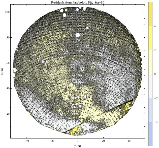

37 Data Processing (Fred Schwab) mm

38 Data Processing (Fred Schwab)
39 Data Processing (Fred Schwab) RMS Differences: r < 50m = 68µm r < 45m = 48µm r < 40m = 38µm RMS of single a measurement: ~ 35µm Difference of two successive runs (best case!) RMS of two subsets of the same run ~ 18µm best case OOF holography: ~ 40µm
40 Estimated error budget Small-scale errors: panel manufacturing plus gravity error: 127 µm residual actuator error: 80 µm 50 µm panel corner setting error: 80 µm panel-scale thermal errors: 100 µm subreflector: 75 µm total small-scale error: = 211 µm Large-scale thermal error: 100 µm 30 µm Total error: = 235 µm ~ 200 µm! 201 µm Current OOF overhead ~ 20 m in 2 hr ~ 17% Potential Scan overhead ~ 10 m in 2 hr ~ 8% Independent of atmospheric opacity Daytime observing becomes possible! 41
41 Ruze Efficiency


42 $86,740 with academic discount!
43 Performance Summary Wind σ 2 Surface RMS η surface 85 GHz η surface 115 GHz Benign Night-time < µm ms -1 ~ ms -1 ~ 8 Tracking Accuracy 235µm µm Surface Efficiency
44 Collaborators Needed! We are currently about to commission three new ~ 3-4mm instruments! Argus MUSTANG 2 U. Mass. / BYU Phased Array Feed + Beamformer All are being funded by current or recent NSF AST Grants! We need to propose two further Proposals: GBT Servo Improvements (PI Mario Garcia-Sanz, CWRU) New Surface Measurement System (PI me) Please come by and talk to me in the next few days!

45 Thank you!
Generalities on Metrology and Microwave Holography
 Generalities on Metrology and Microwave Holography Richard Prestage National Radio Astronomy Observatory Second Sardinian Summer School on Radio Astronomy and Radio Science Outline of Talk Part I: General
Green Bank Telescope Performance
 Green Bank Telescope Performance Dana S. Balser GBT Performance July 2007 Pune, NCRA Telescope Structure Unblocked Aperture Frequency Coverage Telescope Control Focus Surface Pointing Pointing Requirements
Out-Of-Focus Holography at the Green Bank Telescope
 Astronomy & Astrophysics manuscript no. gbtoofpaper January 2, 27 (DOI: will be inserted by hand later) Out-Of-Focus Holography at the Green Bank Telescope B. Nikolic,2, R. M. Prestage, D. S. Balser, C.
The GBT Precision Telescope Control System. Kim Constantikes
 The GBT Precision Telescope Control System Kim Constantikes Ohio University May 24, 2004 Overview The Green Bank Telescope Scientific Requirements and Objectives The Real Telescope Instrumentation Next
1 General Considerations: Point Source Sensitivity, Surface Brightness Sensitivity, and Photometry
 MUSTANG Sensitivities and MUSTANG-1.5 and - Sensitivity Projections Brian S. Mason (NRAO) - 6sep1 This technical note explains the current MUSTANG sensitivity and how it is calculated. The MUSTANG-1.5
Phase-Referencing and the Atmosphere
 Phase-Referencing and the Atmosphere Francoise Delplancke Outline: Basic principle of phase-referencing Atmospheric / astrophysical limitations Phase-referencing requirements: Practical problems: dispersion
x Contents Segmented Mirror Telescopes Metal and Lightweight Mirrors Mirror Polishing
 Contents 1 Fundamentals of Optical Telescopes... 1 1.1 A Brief History of Optical Telescopes.................... 1 1.2 General Astronomical Requirements..................... 6 1.2.1 Angular Resolution.............................
CHARA 2014 Science & Technology Review. NPOI Update. 24 March 2014 Don Hutter
 CHARA 2014 Science & Technology Review 24 March 2014 Don Hutter The BASICS NPOI = Navy Precision Optical Interferometer Major funding by Oceanographer of the Navy and Office of Naval Research NPOI is collaboration
Metrology and Control of Large Telescopes
 T. Pisanu tpisanu@oa-cagliari.inaf.it on behalf of Metrology team* *G. Serra, S. Poppi, F. Buffa, P. Marongiu, R. Concu, G. Vargiu, P. Ortu, A. Saba, E.Urru, G. Deiana Astronomical Observatory of Cagliari
Deconvolving Primary Beam Patterns from SKA Images
 SKA memo 103, 14 aug 2008 Deconvolving Primary Beam Patterns from SKA Images Melvyn Wright & Stuartt Corder University of California, Berkeley, & Caltech, Pasadena, CA. ABSTRACT In this memo we present
The Principles of Astronomical Telescope Design
 The Principles of Astronomical Telescope Design Jingquan Cheng National Radio Astronomy Observatory Charlottesville, Virginia,.USA " 4y Springer Fundamentals of Optical Telescopes 1 1.1 A Brief History
Analysis on the track unevenness and alidade temperature behavior of TM65m antenna
 Analysis on the track unevenness and alidade temperature behavior of TM65m antenna Li Fu, Quan-bao Ling, Rong-bing Zhao, Jinqing Wang, Xu-guang Geng, Yong-bin Jiang, Lin-feng Yu, Wei Gou 20 th September,2016
A New Spectrometer for the Green Bank Telescope
 A New Spectrometer for the Green Bank Telescope Marty Bloss, Patrick Brandt, Hong Chen, Jayanth Chennamangalam, Jeff Cobb, Ramon Creager, Paul Demorest, Glenn Jones, Randy McCullough, Jason Ray, D. Anish
Atmospheric phase correction for ALMA with water-vapour radiometers
 Atmospheric phase correction for ALMA with water-vapour radiometers B. Nikolic Cavendish Laboratory, University of Cambridge January 29 NA URSI, Boulder, CO B. Nikolic (University of Cambridge) WVR phase
RF properties. of the Planck telescope. Designed by ALCATEL. CASE No. 1. Per Heighwood Nielsen
 TICRA engineering consultants communications systems and antennas RF properties of the Planck telescope Designed by ALCATEL CASE No. 1 November, 1999 S-801-04 Author: Per Heighwood Nielsen TICRA KRON PRINSENS
NATIONAL RADIO ASTRONOMY OBSERVATORY MEMORANDUM
 NATIONAL RADIO ASTRONOMY OBSERVATORY MEMORANDUM DATE: September 16, 1996 TO: M. Clark, B. Garwood, D. Hogg, H. Liszt FROM: Ron Maddalena SUBJECT: GBT and Aips++ requirements for traditional, all-sky pointing
Millimeter Antenna Calibration
 Millimeter Antenna Calibration 9 th IRAM Millimeter Interferometry School 10-14 October 2016 Michael Bremer, IRAM Grenoble The beam (or: where does an antenna look?) How and where to build a mm telescope
Control of the Keck and CELT Telescopes. Douglas G. MacMartin Control & Dynamical Systems California Institute of Technology
 Control of the Keck and CELT Telescopes Douglas G. MacMartin Control & Dynamical Systems California Institute of Technology Telescope Control Problems Light from star Primary mirror active control system
How to improve the high-frequency capabilities of the SRT
 Mem. S.A.It. Suppl. Vol. 10, 136 c SAIt 2006 Memorie della Supplementi How to improve the high-frequency capabilities of the SRT T. Pisanu 1, F. Buffa 2, M. Morsiani 3, M. Natalini 1, C. Pernechele 2,
Planning (VLA) observations
 observations") Planning () observations Loránt Sjouwerman, NRAO Sixteenth Synthesis Imaging Workshop 16-23 May 2018 Outline General advice on planning any (ground based) observation AUI telescopes: the GBT, ALMA, VLBA,
Planning () observations Loránt Sjouwerman, NRAO Sixteenth Synthesis Imaging Workshop 16-23 May 2018 Outline General advice on planning any (ground based) observation AUI telescopes: the GBT, ALMA, VLBA,
Plans for Unprecedented Imaging of Stellar Surfaces with the Navy Precision Optical Interferometer (NPOI)
") Plans for Unprecedented Imaging of Stellar Surfaces with the Navy Precision Optical Interferometer (NPOI) A. M. Jorgensen Electrical Engineering Department New Mexico Tech, USA H. R. Schmitt, D. Mozurkewich,
Plans for Unprecedented Imaging of Stellar Surfaces with the Navy Precision Optical Interferometer (NPOI) A. M. Jorgensen Electrical Engineering Department New Mexico Tech, USA H. R. Schmitt, D. Mozurkewich,
Multicolor mm/submm TES Bolometer Camera development for ASTE. Tai Oshima (NRO/NAOJ)
") Multicolor mm/submm TES Bolometer Camera development for ASTE Tai Oshima (NRO/NAOJ) Science with the Multicolor camera AzTEC mm camera on ASTE(2007-2008) lots of successful observation projects What comes
Multicolor mm/submm TES Bolometer Camera development for ASTE Tai Oshima (NRO/NAOJ) Science with the Multicolor camera AzTEC mm camera on ASTE(2007-2008) lots of successful observation projects What comes
Continuum Observing. Continuum Emission and Single Dishes
 July 11, 2005 NAIC/NRAO Single-dish Summer School Continuum Observing Jim Condon Continuum Emission and Single Dishes Continuum sources produce steady, broadband noise So do receiver noise and drift, atmospheric
The Robert C. Byrd Green Bank Telescope
 The Robert C. Byrd Green Bank Telescope Phil Jewell National Radio Astronomy Observatory 520 Edgemont Road Charlottesville, VA 22903-2475 USA pjewell@nrao.edu NAIC-NRAO School on Single Dish Radio Astronomy
Background, theory and practical limitations of metrology systems at Radio Astronomy Antennas
 Metrology Systems for Radio Astronomy at MTM Background, theory and practical limitations of metrology systems at Radio Astronomy Antennas Chalmers University of Technology, Gothenburg, Sweden September
CHARA Collaboration Year-Eight Science Review. VLTI update. F. Delplancke
 VLTI update F. Delplancke Summary Infrastructure Current instruments: MIDI, AMBER, PIONIER Under test & commissioning: PRIMA 2 nd generation instruments Long Range Plan Infrastructure Infrastructure 4
Disturbance Feedforward Control for Vibration Suppression in Adaptive Optics of Large Telescopes
 Disturbance Feedforward Control for Vibration Suppression in Adaptive Optics of Large Telescopes Martin Glück, Jörg-Uwe Pott, Oliver Sawodny Reaching the Diffraction Limit of Large Telescopes using Adaptive
Radio Astronomy An Introduction
 Radio Astronomy An Introduction Felix James Jay Lockman NRAO Green Bank, WV References Thompson, Moran & Swenson Kraus (1966) Christiansen & Hogbom (1969) Condon & Ransom (nrao.edu) Single Dish School
Feedback Control of Linear SISO systems. Process Dynamics and Control
 Feedback Control of Linear SISO systems Process Dynamics and Control 1 Open-Loop Process The study of dynamics was limited to open-loop systems Observe process behavior as a result of specific input signals
McMath-Pierce Adaptive Optics Overview. Christoph Keller National Solar Observatory, Tucson
 McMath-Pierce Adaptive Optics Overview Christoph Keller National Solar Observatory, Tucson Small-Scale Structures on the Sun 1 arcsec Important astrophysical scales (pressure scale height in photosphere,
EM Simulations using the PEEC Method - Case Studies in Power Electronics
 EM Simulations using the PEEC Method - Case Studies in Power Electronics Andreas Müsing Swiss Federal Institute of Technology (ETH) Zürich Power Electronic Systems www.pes.ee.ethz.ch 1 Outline Motivation:
A Straight Forward Path (Roadmap) to EUV High Brightness LPP Source
 to EUV High Brightness LPP Source") Introduction and Outline A Straight Forward Path (Roadmap) to EUV High Brightness LPP Source Rainer Lebert, AIXUV Target Features of High Brightness EUV Source LPP Concept to reach Specification Target
Introduction and Outline A Straight Forward Path (Roadmap) to EUV High Brightness LPP Source Rainer Lebert, AIXUV Target Features of High Brightness EUV Source LPP Concept to reach Specification Target
April 30, 1998 What is the Expected Sensitivity of the SMA? SMA Memo #125 David Wilner ABSTRACT We estimate the SMA sensitivity at 230, 345 and 650 GH
 April 30, 1998 What is the Expected Sensitivity of the SMA? SMA Memo #125 David Wilner ABSTRACT We estimate the SMA sensitivity at 230, 345 and 650 GHz employing current expectations for the receivers,
The Arecibo L-Band Feed Array ALFA Front-End Optics
 The Arecibo L-Band Feed Array ALFA Front-End Optics Germán Cortés Medellín Arecibo L-Band Feed Array G. Cortés, NRAO, Charlottesville, 2003 1-1 Outline ALFA Specifications Feed Horn Characteristics Antenna
Position and Velocity Profile Tracking Control for New Generation Servo Track Writing
 Preprints of the 9th World Congress The International Federation of Automatic Control Cape Town, South Africa. August 24-29, 24 Position and Velocity Profile Tracking Control for New Generation Servo Track
Expected Performance From WIYN Tip-Tilt Imaging
 Expected Performance From WIYN Tip-Tilt Imaging C. F. Claver 3 September 1997 Overview Image motion studies done at WIYN show that a significant improvement to delivered image quality can be obtained from
Primary Mirror Cell Deformation and Its Effect on Mirror Figure Assuming a Six-zone Axial Defining System
 Primary Mirror Cell Deformation and Its Effect on Mirror Figure Larry Stepp Eugene Huang Eric Hansen Optics Manager Opto-structural Engineer Opto-mechanical Engineer November 1993 GEMINI PROJECT OFFICE
CDS 101/110a: Lecture 8-1 Frequency Domain Design
 CDS 11/11a: Lecture 8-1 Frequency Domain Design Richard M. Murray 17 November 28 Goals: Describe canonical control design problem and standard performance measures Show how to use loop shaping to achieve
Control for. Maarten Steinbuch Dept. Mechanical Engineering Control Systems Technology Group TU/e
 Control for Maarten Steinbuch Dept. Mechanical Engineering Control Systems Technology Group TU/e Motion Systems m F Introduction Timedomain tuning Frequency domain & stability Filters Feedforward Servo-oriented
Post-Test. For more information, please contact the MCU Training Team.
 Answer the following application questions based on this diagram. Multiple Choice 1. What type of application curve must be used inside a VFD to operate this carpet roll correctly? A) Constant Torque B)
Acknowledgements. Control System. Tracking. CS122A: Embedded System Design 4/24/2007. A Simple Introduction to Embedded Control Systems (PID Control)
") Acknowledgements A Simple Introduction to Embedded Control Systems (PID Control) The material in this lecture is adapted from: F. Vahid and T. Givargis, Embedded System Design A Unified Hardware/Software
Acknowledgements A Simple Introduction to Embedded Control Systems (PID Control) The material in this lecture is adapted from: F. Vahid and T. Givargis, Embedded System Design A Unified Hardware/Software
Memo 106 Composite Applications for Radio Telescopes (CART): The Mk2 Reflector Results.
: The Mk2 Reflector Results.") Memo 106 Composite Applications for Radio Telescopes (CART): The Mk2 Reflector Results. D. Chalmers G. Lacy 01/09 www.skatelescope.org/pages/page_memos.htm 1 SKA Memo 106 Composite Applications for Radio
Memo 106 Composite Applications for Radio Telescopes (CART): The Mk2 Reflector Results. D. Chalmers G. Lacy 01/09 www.skatelescope.org/pages/page_memos.htm 1 SKA Memo 106 Composite Applications for Radio
Commissioning of the Hanle Autoguider
 Commissioning of the Hanle Autoguider Copenhagen University Observatory Edited November 10, 2005 Figure 1: First light image for the Hanle autoguider, obtained on September 17, 2005. A 5 second exposure
Radio Interferometry and ALMA
 Radio Interferometry and ALMA T. L. Wilson ESO 1 PLAN Basics of radio astronomy, especially interferometry ALMA technical details ALMA Science More details in Interferometry Schools such as the one at
Optical interferometry: problems and practice
 Outline Optical interferometry: problems and practice Chris Haniff Aims. What is an interferometer? Fundamental differences between optical and radio. Implementation at optical wavelengths. Conclusions.
Jin Huang,Jie Zhang. Key Laboratory of Electronic Equipment Structure Design Ministry of Education, Xidian University. Sept.
 电子装备结构设计 Metrology and Control of Large Telescopes workshop, 2016, Green Bank, US 教育部重点实验室 Wind Effect and its Compensation for Large Reflector Antennas Jin Huang,Jie Zhang Key Laboratory of Electronic
High (Angular) Resolution Astronomy
 Resolution Astronomy") High (Angular) Resolution Astronomy http://www.mrao.cam.ac.uk/ bn204/ mailto:b.nikolic@mrao.cam.ac.uk Astrophysics Group, Cavendish Laboratory, University of Cambridge January 2012 Outline Science Drivers
High (Angular) Resolution Astronomy http://www.mrao.cam.ac.uk/ bn204/ mailto:b.nikolic@mrao.cam.ac.uk Astrophysics Group, Cavendish Laboratory, University of Cambridge January 2012 Outline Science Drivers
Part I. The Quad-Ridged Flared Horn
 9 Part I The Quad-Ridged Flared Horn 10 Chapter 2 Key Requirements of Radio Telescope Feeds Almost all of today s radio telescopes operating above 0.5 GHz use reflector antennas consisting of one or more
New DCM for spectroscopy an engineering challenge review
 New DCM for spectroscopy an engineering challenge review Y. Dabin, R. Baker, L. Zhang, H. Gonzalez, R. Barrett, Ph. Marion, O. Mathon, R. Tucoulou Page 2 DRIVERS FOR A NEW DCM: GENERAL OUTLINES Page 3
Lecture 12. AO Control Theory
 Lecture 12 AO Control Theory Claire Max with many thanks to Don Gavel and Don Wiberg UC Santa Cruz February 18, 2016 Page 1 What are control systems? Control is the process of making a system variable
1 Naval Research Laboratory Remote Sensing Division, Code Aberdeen Ave SE Kirtland AFB, NM 87117
 Carbon Fiber Reinforced Polymer (CFRP) Telescope Program at the Naval Research Laboratory Sergio R. Restaino 1, Ty Martinez 1, Jonathan R. Andrews 1, Christopher C. Wilcox 1, S. Teare 2, Robert Romeo 3,
Control System Design
 ELEC ENG 4CL4: Control System Design Notes for Lecture #15 Friday, February 6, 2004 Dr. Ian C. Bruce Room: CRL-229 Phone ext.: 26984 Email: ibruce@mail.ece.mcmaster.ca (3) Cohen-Coon Reaction Curve Method
Determining the Specification of an Aperture Array for Cosmological Surveys
 Determining the Specification of an Aperture Array for Cosmological Surveys P. Alexander University of Cambridge, Department of Physics, Cavendish Laboratory, Cambridge, UK. A. J. aulkner Jodrell Bank
Development of a solar imaging array of Very Small Radio Telescopes
 Development of a solar imaging array of Very Small Radio Telescopes Ted Tsiligaridis University of Washington, Seattle Mentor: Alan E.E. Rogers MIT Haystack Observatory Summer 27 Outline 1. Solar Physics
NAOYUKI TAMURA Subaru Instrument Astronomer Subaru Telescope, NAOJ
 FMOS status tt report Science workshop 2011.02.2802 28-03.0202 NAOYUKI TAMURA Subaru Instrument Astronomer Subaru Telescope, NAOJ * Overview * Recent history & current status t * Schedule & future plan
Practical work: Active control of vibrations of a ski mock-up with a piezoelectric actuator
 Jean Luc Dion Gaël Chevallier SUPMECA Paris (Mechanical Engineering School) Practical work: Active control of vibrations of a ski mock-up with a piezoelectric actuator THIS WORK HAS OBTAINED THE FIRST
PAPER 338 OPTICAL AND INFRARED ASTRONOMICAL TELESCOPES AND INSTRUMENTS
 MATHEMATICAL TRIPOS Part III Monday, 12 June, 2017 1:30 pm to 3:30 pm PAPER 338 OPTICAL AND INFRARED ASTRONOMICAL TELESCOPES AND INSTRUMENTS Attempt no more than TWO questions. There are THREE questions
Introduction to Radio Interferometry Jim Braatz (NRAO)
") Introduction to Radio Interferometry Jim Braatz (NRAO) Atacama Large Millimeter/submillimeter Array Expanded Very Large Array Robert C. Byrd Green Bank Telescope Very Long Baseline Array Radio Astronomy
Introduction to Radio Interferometry Jim Braatz (NRAO) Atacama Large Millimeter/submillimeter Array Expanded Very Large Array Robert C. Byrd Green Bank Telescope Very Long Baseline Array Radio Astronomy
The Australia Telescope. The Australia Telescope National Facility. Why is it a National Facility? Who uses the AT? Ray Norris CSIRO ATNF
 The Australia Telescope National Facility The Australia Telescope Ray Norris CSIRO ATNF Why is it a National Facility? Funded by the federal government (through CSIRO) Provides radio-astronomical facilities
Development of Lunar Scintillometer for Probing the Ground Layer Turbulence. Ravinder K. Banyal. Indian Institute of Astrophysics Bangalore
 Development of Lunar Scintillometer for Probing the Ground Layer Turbulence Ravinder K. Banyal Indian Institute of Astrophysics Bangalore 560034 Indo-US meeting on Adaptive optics with moderate-sized Telescopes
CHV Series Vector Control Inverter Options. Operating Instructions for Tension Control Card
 CHV Series Vector Control Inverter Options Operating Instructions for Control Card 1. Model and Specifications 1.1 Model The model of tension card is CHV00ZL. CHV series inverter can conduct constant
Quanser NI-ELVIS Trainer (QNET) Series: QNET Experiment #02: DC Motor Position Control. DC Motor Control Trainer (DCMCT) Student Manual
 Series: QNET Experiment #02: DC Motor Position Control. DC Motor Control Trainer (DCMCT) Student Manual") Quanser NI-ELVIS Trainer (QNET) Series: QNET Experiment #02: DC Motor Position Control DC Motor Control Trainer (DCMCT) Student Manual Table of Contents 1 Laboratory Objectives1 2 References1 3 DCMCT Plant
Quanser NI-ELVIS Trainer (QNET) Series: QNET Experiment #02: DC Motor Position Control DC Motor Control Trainer (DCMCT) Student Manual Table of Contents 1 Laboratory Objectives1 2 References1 3 DCMCT Plant
Palomar Testbed Interferometer (PTI) & Keck Interferometer (KI) Mark Colavita 7/29/2005 Michelson Summer School Pasadena, CA
 & Keck Interferometer (KI) Mark Colavita 7/29/2005 Michelson Summer School Pasadena, CA") Palomar Testbed Interferometer (PTI) & Keck Interferometer (KI) Mark Colavita 7/29/2005 Michelson Summer School Pasadena, CA PTI as seen from the catwalk of the 200 telescope Michelson Interferometer stellar
Palomar Testbed Interferometer (PTI) & Keck Interferometer (KI) Mark Colavita 7/29/2005 Michelson Summer School Pasadena, CA PTI as seen from the catwalk of the 200 telescope Michelson Interferometer stellar
Atacama Submillimeter Telescope. ISM Polarimetry. C. Darren Dowell (JPL/Caltech) 2003 October 11
 2003 October 11") Atacama Submillimeter Telescope ISM Polarimetry C. Darren Dowell (JPL/Caltech) 2003 October 11 Outline Sensitivity Extended Sources: Magnetic fields confront other forces in the Galaxy. Large-scale magnetic
Atacama Submillimeter Telescope ISM Polarimetry C. Darren Dowell (JPL/Caltech) 2003 October 11 Outline Sensitivity Extended Sources: Magnetic fields confront other forces in the Galaxy. Large-scale magnetic
Beam Scan Properties of Nonparabolic Reflectors. P.J. N a p ie r National Radio Astronomy Observatory, Socorro, New Mexico 87801
 NLSRT Memo No.. / / ' /ft Beam Scan Properties of Nonparabolic Reflectors P.J. N a p ie r National Radio Astronomy Observatory, Socorro, New Mexico 87801 Abstract. Nonparabolic reflector systems such as
Submillimeter Array Technical Memorandum
 Submillimeter Array Technical Memorandum Number: 5 Date: August 2, 99 From: Cohn Masson Antenna Surface Measurement for the SMA Summary I discuss the available techniques for measuring the surface of the
Error Budgets, and Introduction to Class Projects. Lecture 6, ASTR 289
 Error Budgets, and Introduction to Class Projects Lecture 6, ASTR 89 Claire Max UC Santa Cruz January 8, 016 Page 1 What is residual wavefront error? Telescope AO System Science Instrument Very distorted
On Practical Applications of Active Disturbance Rejection Control
 2010 Chinese Control Conference On Practical Applications of Active Disturbance Rejection Control Qing Zheng Gannon University Zhiqiang Gao Cleveland State University Outline Ø Introduction Ø Active Disturbance
AOL Spring Wavefront Sensing. Figure 1: Principle of operation of the Shack-Hartmann wavefront sensor
 AOL Spring Wavefront Sensing The Shack Hartmann Wavefront Sensor system provides accurate, high-speed measurements of the wavefront shape and intensity distribution of beams by analyzing the location and
Smart Sensing Embedded Spectroscopy Platform Botlek studiegroep 06-april-2017
 Smart Sensing Embedded Spectroscopy Platform Botlek studiegroep 06-april-2017 W. Karremans Personal introduction Background: Process Analysis DSM AKZO Nobel Chemicals Aspenpharma 2016: Sales Engineer Elscolab
Thermal Behavior of the Leighton 10-m Antenna Backing Structure
 MMA Memo. 3 Thermal Behavior of the Leighton -m Antenna Backing Structure James W Lamb and David P Woody Owens Valley Radio Observatory California Institute of Technology 3 October, 99 Abstract: One of
Control System Design
 ELEC ENG 4CL4: Control System Design Notes for Lecture #13 Monday, February 3, 2003 Dr. Ian C. Bruce Room: CRL-229 Phone ext.: 26984 Email: ibruce@mail.ece.mcmaster.ca (3) Cohen-Coon Reaction Curve Method
Advanced Topic in Astrophysics Lecture 1 Radio Astronomy - Antennas & Imaging
 Advanced Topic in Astrophysics Lecture 1 Radio Astronomy - Antennas & Imaging Course Structure Modules Module 1, lectures 1-6 (Lister Staveley-Smith, Richard Dodson, Maria Rioja) Mon Wed Fri 1pm weeks
Polarization Shearing Interferometer (PSI) Based Wavefront Sensor for Adaptive Optics Application. A.K.Saxena and J.P.Lancelot
 Based Wavefront Sensor for Adaptive Optics Application. A.K.Saxena and J.P.Lancelot") Polarization Shearing Interferometer (PSI) Based Wavefront Sensor for Adaptive Optics Application A.K.Saxena and J.P.Lancelot Adaptive Optics A Closed loop Optical system to compensate atmospheric turbulence
Polarization Shearing Interferometer (PSI) Based Wavefront Sensor for Adaptive Optics Application A.K.Saxena and J.P.Lancelot Adaptive Optics A Closed loop Optical system to compensate atmospheric turbulence
Submillimetre astronomy
 Sep. 20 2012 Spectral line submillimetre observations Observations in the submillimetre wavelengths are in principle not different from those made at millimetre wavelengths. There are however, three significant
Fundamental Limits to Wavefront Sensing in the Submillimeter
 Fundamental Limits to Wavefront Sensing in the Submillimeter E. Serabyn Jet Propulsion Laboratory, California Institute of Technology, 4800 Oak Grove Drive, Pasadena, CA, USA 91109 Copyright 2006 Society
SOFIA Telescope Manufacturing - Lessons Learned
 SOFIA Telescope Manufacturing - Lessons Learned Hans J. Kaercher, Senior Telescope Engineer MT Mechatronics GmbH, Mainz, Germany hans.kaercher@mt-mechatronics.de 1 Experience with Telescopes at Exposed
Tests of the BURLE 64-anode MCP PMT as the detector of Cherenkov photons
 Tests of the BURLE 64-anode MCP PMT as the detector of Cherenkov photons Peter Križan University of Ljubljana and J. Stefan Institute Contents Motivation and requirements BURLE MCP-PMT Beam test results
Chapter 9: Controller design
 Chapter 9. Controller Design 9.1. Introduction 9.2. Effect of negative feedback on the network transfer functions 9.2.1. Feedback reduces the transfer function from disturbances to the output 9.2.2. Feedback
Wide-Fielding ALMA using Phased Array Feed Receivers
 Wide-Fielding ALMA using Phased Array Feed Receivers D. Anish Roshi, W. Shillue, T. Hunter, C. Brogan NRAO, Charlottesville (ALMA Study proposal 2016) Current PAF activity at NRAO Science case for PAF
an NSF Facility Atacama Large Millimeter/submillimeter Array Expanded Very Large Array Robert C. Byrd Green Bank Telescope Very Long Baseline Array
 an NSF Facility Atacama Large Millimeter/submillimeter Array Expanded Very Large Array Robert C. Byrd Green Bank Telescope Very Long Baseline Array ALMA s Contributions to Outflows, Winds and Jets Al Wootten
Stellar Intensity Interferometric Capabilities of IACT Arrays*
 Stellar Intensity Interferometric Capabilities of IACT Arrays* Dave Kieda Nolan Matthews University of Utah Salt Lake City, Utah *for VERITAS and CTA collaborations Photon Bunching & Intensity Interferometry
The Green Bank Telescope: an Overview
 The Green Bank Telescope: an Overview Felix J. Lockman a Library National Radio Astronomy Observatory, P.O. Box 2, Green Bank, WV USA ABSTRACT The Green Bank Telescope, now under construction at the National
Opto-Mechanical I/F for ANSYS
 Opto-Mechanical I/F for ANSYS Victor Genberg, Gregory Michels, Keith Doyle Sigmadyne, Inc. Abstract Thermal and structural output from ANSYS is not in a form useful for optical analysis software. Temperatures,
MECHATRONICS ENGINEERING TECHNOLOGY. Modeling a Servo Motor System
 Modeling a Servo Motor System Definitions Motor: A device that receives a continuous (Analog) signal and operates continuously in time. Digital Controller: Discretizes the amplitude of the signal and also
Measurements of the DL0SHF 8 GHz Antenna
 Measurements of the DL0SHF 8 GHz Antenna Joachim Köppen, DF3GJ Inst.Theoret.Physik u.astrophysik, Univ. Kiel September 2015 Pointing Correction Position errors had already been determined on a few days
Model M3484 Industrial Line Noise Filter Module Customer Reference Manual
 Model M3484 Industrial Line Noise Filter Module Customer Reference Manual Web: www.bonitron.com Tel: 615-244-2825 Email: info@bonitron.com Bonitron, Inc. Bonitron, Inc. Nashville, TN An industry leader
INSTRUMENTAL ENGINEERING
 INSTRUMENTAL ENGINEERING Subject Code: IN Course Structure Sections/Units Section A Unit 1 Unit 2 Unit 3 Unit 4 Unit 5 Unit 6 Section B Section C Section D Section E Section F Section G Section H Section
Study of Solder Ball Bump Bonded Hybrid Silicon Pixel Detectors at DESY
 Study of Solder Ball Bump Bonded Hybrid Silicon Pixel Detectors at DESY S. Arab, S. Choudhury, G. Dolinska, K. Hansen, I. Korol, H. Perrey, D. Pitzl, S. Spannagel ( DESY Hamburg ) E. Garutti, M. Hoffmann,
FEEDBACK CONTROL SYSTEMS
 FEEDBAC CONTROL SYSTEMS. Control System Design. Open and Closed-Loop Control Systems 3. Why Closed-Loop Control? 4. Case Study --- Speed Control of a DC Motor 5. Steady-State Errors in Unity Feedback Control
Lecture 6: Control Problems and Solutions. CS 344R: Robotics Benjamin Kuipers
 Lecture 6: Control Problems and Solutions CS 344R: Robotics Benjamin Kuipers But First, Assignment 1: Followers A follower is a control law where the robot moves forward while keeping some error term small.
R a) Compare open loop and closed loop control systems. b) Clearly bring out, from basics, Force-current and Force-Voltage analogies.
 Compare open loop and closed loop control systems. b) Clearly bring out, from basics, Force-current and Force-Voltage analogies.") SET - 1 II B. Tech II Semester Supplementary Examinations Dec 01 1. a) Compare open loop and closed loop control systems. b) Clearly bring out, from basics, Force-current and Force-Voltage analogies..
SET - 1 II B. Tech II Semester Supplementary Examinations Dec 01 1. a) Compare open loop and closed loop control systems. b) Clearly bring out, from basics, Force-current and Force-Voltage analogies..
Daily Alignment Procedure with 2 AO Wave Front Sensors
 Daily Alignment Procedure with 2 AO Wave Front Sensors First Version Judit Sturmann Talk Outline AO at CHARA design scheme Before sky alignment Keeping the alignment during the night Lab and Telescope
Polarimetry with Phased-Array Feeds
 Polarimetry with Phased-Array Feeds Bruce Veidt Dominion Radio Astrophysical Observatory Herzberg Institute of Astrophysics National Research Council of Canada Penticton, British Columbia, Canada Provo,
Pixellated Planar Bolometer Imaging Arrays
 Pixellated Planar Bolometer Imaging Arrays E. Wollack, D. Chuss, H. Moseley NASA/GSFC Future Telescope Instrumentation Workshop, Green Bank, West Virginia 09/05/06 Summary Pixellated imaging arrays Motivation
GBO Call for Proposals: Semester 2017A
 GBO Call for Proposals: Semester 2017A 30 June 2016 The Green Bank Observatory (GBO) invites scientists to participate in the GBO's Semester 2017A Call for Proposals for the Green Bank Telescope (GBT).
ALMA Water Vapour Radiometry: Tests at the SMA
 ALMA Water Vapour Radiometry: Tests at the SMA P.G.Anathasubramanian 1,4, R.E.Hills 1, K.G.Isaak 1,5, B.Nikolic 1, M.Owen 1, J.S.Richer 1, H.Smith 1, A.J.Stirling 1,6, R.Williamson 1,7, V.Belitsky 2, R.Booth
Vibration Analysis and Control in Particle Accelerator
 Vibration Analysis and Control in Particle Accelerator M. Serluca 1, B. Aimard 1, G. Balik 1, B. Caron 2 L. Brunetti 1, A. Dominjon 1, A. Jeremie 1 (LAViSta Team: Laboratoires d Annecy de Vibration & Stabilisation)
Satellite Attitude Control System Design Using Reaction Wheels Bhanu Gouda Brian Fast Dan Simon
 Satellite Attitude Control System Design Using Reaction Wheels Bhanu Gouda Brian Fast Dan Simon Outline 1. Overview of Attitude Determination and Control system. Problem formulation 3. Control schemes
KINGS COLLEGE OF ENGINEERING DEPARTMENT OF ELECTRONICS AND COMMUNICATION ENGINEERING
 KINGS COLLEGE OF ENGINEERING DEPARTMENT OF ELECTRONICS AND COMMUNICATION ENGINEERING QUESTION BANK SUB.NAME : CONTROL SYSTEMS BRANCH : ECE YEAR : II SEMESTER: IV 1. What is control system? 2. Define open